EP3420444B1 - Verfahren für layout und druck von bildern in mehreren bahnen mit unterschiedlichen wiederholungslängen - Google Patents
Verfahren für layout und druck von bildern in mehreren bahnen mit unterschiedlichen wiederholungslängen Download PDFInfo
- Publication number
- EP3420444B1 EP3420444B1 EP17706984.6A EP17706984A EP3420444B1 EP 3420444 B1 EP3420444 B1 EP 3420444B1 EP 17706984 A EP17706984 A EP 17706984A EP 3420444 B1 EP3420444 B1 EP 3420444B1
- Authority
- EP
- European Patent Office
- Prior art keywords
- image
- substrate
- printing
- rows
- frames
- Prior art date
- Legal status (The legal status is an assumption and is not a legal conclusion. Google has not performed a legal analysis and makes no representation as to the accuracy of the status listed.)
- Active
Links
Images








Classifications
-
- G—PHYSICS
- G06—COMPUTING OR CALCULATING; COUNTING
- G06F—ELECTRIC DIGITAL DATA PROCESSING
- G06F3/00—Input arrangements for transferring data to be processed into a form capable of being handled by the computer; Output arrangements for transferring data from processing unit to output unit, e.g. interface arrangements
- G06F3/12—Digital output to print unit, e.g. line printer, chain printer
- G06F3/1201—Dedicated interfaces to print systems
- G06F3/1202—Dedicated interfaces to print systems specifically adapted to achieve a particular effect
- G06F3/1218—Reducing or saving of used resources, e.g. avoiding waste of consumables or improving usage of hardware resources
- G06F3/1219—Reducing or saving of used resources, e.g. avoiding waste of consumables or improving usage of hardware resources with regard to consumables, e.g. ink, toner, paper
-
- B—PERFORMING OPERATIONS; TRANSPORTING
- B41—PRINTING; LINING MACHINES; TYPEWRITERS; STAMPS
- B41J—TYPEWRITERS; SELECTIVE PRINTING MECHANISMS, i.e. MECHANISMS PRINTING OTHERWISE THAN FROM A FORME; CORRECTION OF TYPOGRAPHICAL ERRORS
- B41J11/00—Devices or arrangements of selective printing mechanisms, e.g. ink-jet printers or thermal printers, for supporting or handling copy material in sheet or web form
- B41J11/008—Controlling printhead for accurately positioning print image on printing material, e.g. with the intention to control the width of margins
-
- B—PERFORMING OPERATIONS; TRANSPORTING
- B41—PRINTING; LINING MACHINES; TYPEWRITERS; STAMPS
- B41J—TYPEWRITERS; SELECTIVE PRINTING MECHANISMS, i.e. MECHANISMS PRINTING OTHERWISE THAN FROM A FORME; CORRECTION OF TYPOGRAPHICAL ERRORS
- B41J11/00—Devices or arrangements of selective printing mechanisms, e.g. ink-jet printers or thermal printers, for supporting or handling copy material in sheet or web form
- B41J11/36—Blanking or long feeds; Feeding to a particular line, e.g. by rotation of platen or feed roller
- B41J11/42—Controlling printing material conveyance for accurate alignment of the printing material with the printhead; Print registering
-
- B—PERFORMING OPERATIONS; TRANSPORTING
- B41—PRINTING; LINING MACHINES; TYPEWRITERS; STAMPS
- B41J—TYPEWRITERS; SELECTIVE PRINTING MECHANISMS, i.e. MECHANISMS PRINTING OTHERWISE THAN FROM A FORME; CORRECTION OF TYPOGRAPHICAL ERRORS
- B41J15/00—Devices or arrangements of selective printing mechanisms, e.g. ink-jet printers or thermal printers, specially adapted for supporting or handling copy material in continuous form, e.g. webs
- B41J15/04—Supporting, feeding, or guiding devices; Mountings for web rolls or spindles
-
- B—PERFORMING OPERATIONS; TRANSPORTING
- B41—PRINTING; LINING MACHINES; TYPEWRITERS; STAMPS
- B41J—TYPEWRITERS; SELECTIVE PRINTING MECHANISMS, i.e. MECHANISMS PRINTING OTHERWISE THAN FROM A FORME; CORRECTION OF TYPOGRAPHICAL ERRORS
- B41J2/00—Typewriters or selective printing mechanisms characterised by the printing or marking process for which they are designed
- B41J2/005—Typewriters or selective printing mechanisms characterised by the printing or marking process for which they are designed characterised by bringing liquid or particles selectively into contact with a printing material
- B41J2/0057—Typewriters or selective printing mechanisms characterised by the printing or marking process for which they are designed characterised by bringing liquid or particles selectively into contact with a printing material where an intermediate transfer member receives the ink before transferring it on the printing material
-
- G—PHYSICS
- G06—COMPUTING OR CALCULATING; COUNTING
- G06F—ELECTRIC DIGITAL DATA PROCESSING
- G06F3/00—Input arrangements for transferring data to be processed into a form capable of being handled by the computer; Output arrangements for transferring data from processing unit to output unit, e.g. interface arrangements
- G06F3/12—Digital output to print unit, e.g. line printer, chain printer
- G06F3/1201—Dedicated interfaces to print systems
- G06F3/1223—Dedicated interfaces to print systems specifically adapted to use a particular technique
- G06F3/1237—Print job management
- G06F3/1242—Image or content composition onto a page
- G06F3/1243—Variable data printing, e.g. document forms, templates, labels, coupons, advertisements, logos, watermarks, transactional printing, fixed content versioning
-
- G—PHYSICS
- G06—COMPUTING OR CALCULATING; COUNTING
- G06F—ELECTRIC DIGITAL DATA PROCESSING
- G06F3/00—Input arrangements for transferring data to be processed into a form capable of being handled by the computer; Output arrangements for transferring data from processing unit to output unit, e.g. interface arrangements
- G06F3/12—Digital output to print unit, e.g. line printer, chain printer
- G06F3/1201—Dedicated interfaces to print systems
- G06F3/1223—Dedicated interfaces to print systems specifically adapted to use a particular technique
- G06F3/1237—Print job management
- G06F3/125—Page layout or assigning input pages onto output media, e.g. imposition
- G06F3/1251—Page layout or assigning input pages onto output media, e.g. imposition for continuous media, e.g. web media, rolls
-
- G—PHYSICS
- G06—COMPUTING OR CALCULATING; COUNTING
- G06F—ELECTRIC DIGITAL DATA PROCESSING
- G06F3/00—Input arrangements for transferring data to be processed into a form capable of being handled by the computer; Output arrangements for transferring data from processing unit to output unit, e.g. interface arrangements
- G06F3/12—Digital output to print unit, e.g. line printer, chain printer
- G06F3/1201—Dedicated interfaces to print systems
- G06F3/1278—Dedicated interfaces to print systems specifically adapted to adopt a particular infrastructure
- G06F3/1285—Remote printer device, e.g. being remote from client or server
Definitions
- This invention relates to printing systems and methods of printing and generally relates to side-by-side printing of labels that have different repeat lengths on the same continuous web of substrate (e.g. paper).
- the invention seeks to reduce or eliminate white space on the printed paper caused by the different repeat lengths of the labels.
- the substrate e.g. paper
- information e.g. labels
- Labels are typically printed in "frames" of a specified length as dictated by physical/technological limitations of the printer, and then repeated along the length of the web.
- US 2014/199105 A1 discloses a continuous printing unit which prints the input data with a margin length of the input data to be printed adjacent to each other among the plurality of input data set to a predetermined length without using the margin information respectively included in the input data to be printed adjacent to each other.
- US 2013/050384 A1 discloses a printing apparatus comprises a conveying section configured to convey a belt-like storing medium in a first conveying direction or a second conveying direction in which opposite to the first conveying direction.
- customers may want to print multiple labels (e.g. two or more) in different lanes next to each other (e.g. side-by-side) along the web. If the labels have the same size, then they also have the same repeat length (i.e. their tops and bottoms align with each other side-by-side on the web), and therefore fit equally in the designated "frames.” However if labels have different sizes, then they also have different repeat lengths (i.e. they do not exactly align with each other when printed side-by-side), and therefore they do not fit equally within a given frame. This misalignment results in wasted substrate due to white space between label frames or partially printed labels within a frame.
- This invention relates to multiple labels being printed on a continuous web-fed press, using parallel lanes on the web (i.e. printed side-by-side).
- each of the different labels has a different repeat length, and are printed on web-fed presses in a continuous manner (e.g. a roll of paper is fed into the press from a roll, and as the paper passes through the press, labels get printed on the paper).
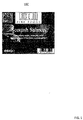
- Fig. 1 Shown in Fig. 1 is an example of a product label that will be utilized for examples described throughout the detailed description.
- label 100 in Fig. 1 is shown as being relatively rectangular or square in shape, it is known that labels may take on any geometric shape (e.g., circle, triangle, etc.) for ultimately placing on a particular product.
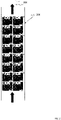
- Fig. 2 Shown in Fig. 2 is an overhead view of a continuous web 200 that has multiple labels 100 printed thereon as the web is fed in direction 202.
- the multiple labels are distributed across and along the web in order to minimize the loss of the substrate (i.e., minimize white space).
- Fig. 2 shows that the labels are printed in eight rows and two columns along the web.
- the black rectangles on the right side of the web are marks placed on the web which are used by a finishing device (e.g., cutting device, not shown) further down the production line.
- the number of columns could be any integer number greater than or equal to 1.
- the number of columns could be set based on width of the web and width of each label as well as other factors.
- data may be split into frames based on physical/technological limitations of the printer.
- the data stream is split into rectangular frames based on memory limitations.
- the data stream is split into rectangular frames based on the circumference of the drum.
- Fig. 3 in which the serial rows of labels are split into frames 204, 206 and 208, which each include three rows and two columns of the label (last row of frame 208 not shown to avoid clutter in the drawing). These frames are illustrated in Fig. 3 as bounded by dark black lines.
- Frames 204, 206 and 208 are then printed on web 200 as web 200 is fed into the printer in direction 202 (i.e., the feed direction).
- the length of the frame (e.g., three labels vertically) is called the repeat length (i.e., when the frame repeats itself).
- the data stream may be sliced into frames for various reasons including (1) the size of internal memory buffers in digital printers, and (2) the use of an intermediate drum to apply ink before transferring the ink onto the substrate. These two situations are now explained in more detail with reference to Figs. 4 and 5 .
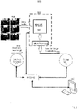
- FIG. 4 Shown in Fig. 4 is a system diagram for an intermediate drum printing system.
- the intermediate drum printing system includes an intermediate drum 404, an input roll 408 of the substrate, an output roll 406 of the substrate, a microcontroller unit MCU 412 and a computer 410 for controlling the overall printing operation.
- the substrate moves in direction 414 as the substrate unwinds from input roll 408 and is rewound on output roll 406.
- Intermediate drum 404 applies the ink to the substrate as shown as element 416.
- the drum circumference is an upper limit for the length of the frame to be printed (i.e., the ink portion of the drum has a circumference and therefore dictates the length of the frame/repeat length for printing the labels 402).
- the frame size/repeat length can be a maximum of 1 meter.
- labels 402 may be applied to the drum in the form of ink which is then rolled onto substrate to produce the printed labels 416.
- Intermediate drum 404 effectively transfers the ink image onto the substrate.
- Operation of the intermediate drum system 400 shown in Fig. 4 is controlled by a computer 410 that may be used by an operator of the printer.
- the operator may send commands to microcontroller unit 412 which then controls the direction and speed of intermediate roller 404, input roller 408, output roller 406, as well as ink of the intermediate drum among others.
- the printer may be a digital printing system 500 that includes an ink jet printer 502 having both internal memory 504 and ink jet heads 506 for applying ink to the substrate.
- the ink jet printing system also includes an input roll 408 and an output roll 406, which together move the substrate in direction 414 underneath ink jet heads 506, which ultimately apply ink to the substrate to create the transferred image 416.
- the ink jet printing system may include a microcontroller unit 412 and a computer 410 for controlling the overall printing system.
- the computer 410 stores label frame 402 in internal memory 504 of the ink jet printer 502.
- the computer 410 then instructs the microcontroller unit 412 to control the speed and direction of input roll 408 and output roll 406, as well as the printing operation of ink jet heads 506 based on label frame 402.
- the digital printer system 500 in Fig. 5 uses internal memory buffers 504 to store the data (i.e., the frames) which need to be printed, the size of these buffers will define an upper limit for the frame to be printed (e.g., the frame 402 may have a maximum size of three rows by two columns because of limited memory in internal memory 504).
- users may want to print multiple labels in different lanes next to each other (i.e. side-by-side) on the same wide web.
- the different lanes may later be separated to accommodate existing finishing devices (e.g., the devices that cut and perform other finishing processes on the printed labels) made for use with a narrower web (e.g. half the width of the wide web).
- the web may be cut immediately after the printing process to enable the finishing device to work on a narrower web.
- Figures 6-18 show examples of configuring and printing two types of labels (see Fig. 6 ) side-by-side on the same web. It should be noted, however, that the number of different types of labels printed side-by-side on the same web could be any integer number greater than or equal to 2 (i.e. there could be more than two lanes of labels). The number of different types of labels to be printed may be set based on width of the web and width of each label as well as other factors.
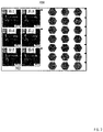
- Fig. 6 shows square product labels 402 (referred to as Label A) and the hexagonal labels 600 (referred to as Label B), in which Label B has a much smaller height than Label A.
- the printing system needs to assign frame sizes that accommodate both labels. Having a single frame for both labels is shown in two different examples as frame 700 in Fig. 7 and frame 800 in Fig. 8 .
- the different repeat lengths inherently cause one of two scenarios.
- the frame includes white space 702 below the square labels if the frame size is dictated by the repeat length of smaller Label B.
- bottom row 802 of Label B may be partially cut off (i.e., the bottom row only partially fits in the frame). Absent implementation of one of the embodiments of the present invention, printing two different labels having two different repeat lengths on the same web may result in either unprinted white space, which is a waste of the substrate, or a repeating pattern of partially printed labels with a discontinuity between the partially printed labels rendering the partial labels unusable, and therefore also wasteful.
- the solution avoids both unwanted white space and partially printed labels by performing either a digital shift of the data in the frame, or a physical shift of the substrate during the printing process.
- a full layout of the frame is postponed until after a RIP (i.e., Raster Image Processing) process is performed which converts an image into raster graphics such as a bitmap that can be utilized by the printer.
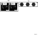
- the labels may be put through the RIP (i.e., converted from an image file to a bitmap) on a row by row basis as shown by row 900 and row 902 of label A and label B in Fig. 9 .
- Each of the two rows 900 and 902 shown in Fig. 9 are considered to be a respective cell of labels (e.g. Cell A and Cell B).
- each cell is not restricted to the size shown in Fig. 9 , but may contain multiple label rows as shown by cell 1000 in Fig. 10 (i.e. Cell 900 in Fig. 9 is duplicated to create a larger cell).
- the system e.g., computer 410 duplicates the cells in either Figs. 9 or 10 to generate a complete frame of labels.
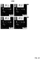
- This complete frame is shown, for example, as complete frame 1100 in Fig. 11 which includes three rows of label A and seven rows of label B.
- Frame 1100 shown in Fig. 11 also includes white space 1102 due to the different lengths of label A and label B.
- each frame includes repeat lengths RL1, RL2 and RL3 which are less than the overall frame heights for each of the frames 1204, 1206 and 1208.
- This whitespace is the amount of distance that the image frames need to be shifted to eliminate the white space between respective frames. This distance translates into a physical distance that the substrate may be shifted during the printing process in order to ensure the labels are continuously printed without any white space.
- the microcontroller unit 412 utilizes distances 1216 and 1218 in order to control the substrate to properly print the labels in a continuous manner (i.e. converts the pixel distance to a physical distance). For example, at the end of printing the labels from frame 1204, the microcontroller unit 412 instructs either the intermediate printing drum 404 or the ink jet printer 502 to stop printing while microcontroller 412 instructs input roll 408 and output roll 406 to stop feeding the substrate in direction 414, and to shift backwards in the opposite direction by the distance corresponding to space 1216.
- the microcontroller unit 412 instructs the printer to resume printing. This stopping and shifting process is again performed between the frame 1206 and frame 1208 to shift the web the distance dictated by 1218. This results in printed results 1202 without the white spaces and without any discontinuities between partial labels.
- step 1500 the label file is opened and rows of label A and label B are extracted.
- step 1502 the rows are then RIPed (i.e. converted) into first and second label bit maps (e.g. bitmap A and bitmap B).
- step 1504 the system defines a first cell (e.g. Cell A) based on the first label bitmap, and defines a second cell (e.g. Cell B) based on the second label bitmap.
- step 1506 duplicates Cell A and Cell B side-by-side multiple times in order to produce a larger bitmap that includes frames of repeating rows for both label A and label B.
- step 1508 the system then controls the printer to pause printing, physically reverse and shift the continuous web by a predetermined amount of distance between each frame and then resume printing. This results in continuously printed labels without white space between the frames.
- each of the N labels is: 1) extracted from their respective files, 2) RIPed (i.e. converted) into bitmaps, 3) defined as N respective Cells, and then 4) duplicated side-by-side in order to produce the larger bitmap of N lanes for printing.
- another post-RIP solution may simply RIP each page of a multi-page label file (e.g., a multi-page PDF) rather than creating the smaller cells.
- a multi-page label file e.g., a multi-page PDF
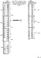
- Fig. 13 shows a multi-page label file 1300 which includes pages 1304, 1306, 1308 and 1310. Each of these pages within the PDF file includes white spaces between each page. These white spaces between each page are shown as 1320, 1322 and 1324, respectively.
- the computer RIPs each one of these PDF pages one by one into a bitmap.
- This bitmap may then be passed along to the printer, where the printer performs a digital shift on each of the RIPed bitmaps in order to produce frames that do not include white space.
- the printer may shift the RIPed digital images 1304, 1306 1308 and 1310 to eliminate white spaces 1320, 1322 and 1324 thereby producing frames 1312, 1314 and 1316 that do not include white space. Since these composed frames do not include white space, they can simply be printed (i.e. physical shift is not needed).
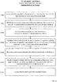
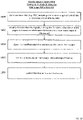
- step 1600 the system opens the multi-page label file and extracts the pages.
- step 1602 the system then RIPs these multiple pages into multiple bitmaps.
- step 1604 the system determines the white space between these bitmaps.
- step 1606 the system then creates frames by digitally shifting each of the bitmaps by a specifically determined distance in order to ensure that the white space is reduced or eliminated between the frames.
- step 1608 the system then controls the printer to print the frames.
- the printing algorithm in Fig. 16 is similar. This is because the multi-page label file is RIPed on a page-by-page basis regardless of how many labels are positioned side-by-side within the file.
- Fig. 12 suggests a post-RIP solution that utilizes label cells and physically shifts the web during printing.
- Fig. 13 also suggests a post-RIP solution that generates frames from each page of a multi-page PDF and then digitally shifts the frames.
- these two solutions may be combined as a hybrid solution.
- the frames may be generated based on cells similar to Fig. 12 but then digitally shifted (not physically shifted) similar to Fig. 13 .
- step 1700 the system opens the multi-page PDF file and extracts one or more rows of labels.
- step 1702 the system RIPs the rows to generate a first label bitmap and a second label bitmap (e.g. bitmap A and bitmap B).
- step 1704 the system defines a first cell (e.g. Cell A) based on the first label bitmap, and defines a second cell (e.g. Cell B) based on the second label bitmap.
- step 1706 the system duplicates Cell A and Cell B side-by-side to produce a larger bitmap that includes a frame of repeating rows.
- step 1708 the system determines white space between the one or more frames in the bitmap.
- step 1710 rather than physically shifting the web, the system digitally shifts the bit map in order to eliminate the white space. This process produces modified frames which are then printed in step 1712.
- each of the N labels is: 1) extracted from the file, 2) RIPed (i.e. converted) into N bitmaps, 3) defined as respective N Cells, and then 4) duplicated side-by-side in order to produce the larger bitmap for printing.
- the system may also be implemented in a pre-RIP solution (i.e., performing the shifting prior to RIP of the label files into bit maps).
- the multi-page PDF 1300 shown in Fig. 13 includes pages 1304, 1306, 1308 and 1310 having white space between the pages within the PDF file itself. Rather than waiting to shift this data post-RIP, this data may be shifted within the PDF file itself.
- the multi-page PDF 1300 shown in Fig. 13 may actually shift the data within the PDF to eliminate white spaces 1320, 1322 and 1324 as shown in the multi-page PDF 1400 which includes pages 1404, 1406 and 1408 which do not include white space between each frame. Since the white space has already been eliminated, the system can simply RIP each page of the PDF and then perform printing.
- step 1800 the system generates a label file (e.g., a multi-page PDF) which includes one or more pages of label A and label B.
- a label file e.g., a multi-page PDF
- this PDF file is actually modified by digitally shifting the data within the PDF file to eliminate the white space.
- the modified PDF file is then opened and then extracted.
- step 1806 the PDF file data is then RIPed into a bit map of frames.
- step 1808 the printer is controlled in order to print the RIPed frames.
- the printing algorithm in Fig. 18 is similar.
- the multi-page PDF is: 1) opened, 2) modified by digitally shifting the data, 3) and then RIPed into a bit map of frames for printing. This is because the data in the multi-page PDF is digitally shifted prior to RIP processing regardless of how many labels are positioned side-by-side within the PDF.
- the present invention is able to either reduce or eliminate white space or discontinuities when printing labels of different repeat lengths side by side on the same web.
- the white space or discontinuities can be eliminated either post-RIP (i.e., after converting to a bitmap) or pre-RIP (i.e., prior to converting to a bitmap).
- the shifting process can either be performed digitally (e.g., in the PDF file or in the bitmap files) or physically (e.g., the web can be stopped and reversed during the printing process). In either case, the white space is removed to ensure continuous printing of labels.
- the spacing between adjacent images may be intentionally adjusted to optimize the number of groupings in the series (e.g. pages in the multipage document).
- adjacent composite image groupings e.g. pages or bitmap frames
Landscapes
- Engineering & Computer Science (AREA)
- Theoretical Computer Science (AREA)
- Human Computer Interaction (AREA)
- Physics & Mathematics (AREA)
- General Engineering & Computer Science (AREA)
- General Physics & Mathematics (AREA)
- Record Information Processing For Printing (AREA)
- Ink Jet (AREA)
Claims (6)
- Drucksystem (400, 500), aufweisend:einen Druckmechanismus zum Auftragen von Tinte auf ein Substrat;eine Substratzuführung zum Positionieren einer kontinuierlichen Substratbahn relativ zu dem Druckmechanismus, um Tinte aufzunehmen, wobeidie Substratzuführung konfiguriert ist, das Substrat mindestens in einer Vorwärtsrichtung derart vorwärts zu bewegen, dass das Substrat, das in der Vorwärtsrichtung an dem Druckmechanismus vorbei vorwärts bewegt wurde, die aufgetragene Tinte enthält; undeine Drucksteuerung, die konfiguriert ist, auf digitale Informationen zuzugreifen, die auf computerlesbaren Medien gespeichert sind, wobei die gespeicherten digitalen Information verkörpern:eine Reihe von zusammengesetzten Bildgruppierungen (1204, 1206, 1208), wobei jede zusammengesetzte Bildgruppierung innerhalb einer definierten Grenze eine oder mehrere Reihen eines ersten Bilds (A) enthält, die einen ersten Wiederholungsabstand nebeneinanderliegend mit einer oder mehreren Reihen eines zweiten Bilds (B) haben, die einen zweiten Wiederholungsabstand haben, der von dem ersten Wiederholungsabstand verschieden ist, wobei das erste Bild einem ersten Beschriftungstyp entspricht, der auf das Substrat gedruckt werden soll, und das zweite Bild einem zweiten Beschriftungstyp entspricht, der auf das Substrat gedruckt werden soll, wobei benachbarte zusammengesetzte Bildgruppierungen in der Reihe nicht identisch sind; undAnweisungen zum Bedienen der Substratzuführung und des Druckmechanismus;wobei die Drucksteuerung ferner konfiguriert ist, den Druckmechanismus und Substratzuführung basierend auf den gespeicherten digitalen Informationen zu steuern, um das Drucken der ersten und zweiten Bilder auf einer kontinuierlichen Substratbahn ohne überflüssigen Leerraum zwischen benachbarten Bildern oder Diskontinuitäten zwischen Teilbildern in benachbarten zusammengesetzten Bildgruppierungen zu bewirken, die durch den unterschiedlichen ersten und zweiten Wiederholungsabstand verursacht werden:am Ende des Druckens einer ersten zusammengesetzten Bildgruppierung (1204) der Reihe von zusammengesetzten Bildgruppierungen, Stoppen des Drucken, dann physisches Verschieben des Substrats in eine Gegenrichtung entgegengesetzt der Vorwärtsrichtung um einen Abstand zum Verschieben des Substrats, und dann Fortsetzen des Druckens einer zusammengesetzten Bildgruppierung (1206) benachbart zu der ersten zusammengesetzten Bildgruppierung (1204),wobei die Drucksteuerung konfiguriert ist, den Abstand zum Verschieben des Substrats zu bestimmen durch Messen eines Abstands (1216) zwischen einer Unterseite einer unteren Instanz des ersten Bilds (A) in der ersten zusammengesetzten Bildgruppierung (1204) zu einer Oberseite einer oberen Instanz des ersten Bilds (A) in der zusammengesetzten Bildgruppierung (1206) zugeordnet ist, benachbart zu der ersten zusammengesetzten Bildgruppierung (1204).
- Drucksystem (400, 500), aufweisend:einen Druckmechanismus zum Auftragen von Tinte auf ein Substrat;eine Substratzuführung zum Positionieren einer kontinuierlichen Substratbahn relativ zu dem Druckmechanismus, um Tinte aufzunehmen,wobei die Substratzuführung konfiguriert ist, das Substrat mindestens in einer Vorwärtsrichtung vorwärts zu bewegen, so dass das Substrat, das in der Vorwärtsrichtung an dem Druckmechanismus vorbei vorwärts bewegt wurde, die aufgetragene Tinte enthält; undeine Drucksteuerung, die konfiguriert ist, auf digitale Informationen zuzugreifen, die auf computerlesbaren Medien gespeichert sind, wobei die gespeicherten digitalen Informationen verkörpern:eine Beschriftungsdatei (1300), die eine oder mehrere Reihen eines ersten Bilds (A) und eine oder mehrere Reihen eines zweiten Bilds (B) aufweist; undAnweisungen zur Bedienung der Substratzuführung und des Druckmechanismus;wobei die Drucksteuerung ferner konfiguriert ist, den Druckmechanismus und die Substratzuführung basierend auf den gespeicherten digitalen Informationen zu steuern, um das Drucken der ersten und zweiten Bilder auf einer kontinuierlichen Substratbahn ohne überflüssigen Leerraum zwischen benachbarten Bildern oder Diskontinuitäten zwischen Teilbildern zu bewirken, durch:Extrahieren, aus der Beschriftungsdatei (1300), von einer oder mehreren Reihen des ersten Bilds (A) und einer oder mehreren Reihen des zweiten Bilds (B);Rasterbildverarbeiten der extrahierten einen oder mehreren Reihen des ersten Bilds (A) in eine erste Bildrastergrafik;Rasterbildverarbeiten der extrahierten einen oder mehreren Reihen des zweiten Bilds (B) in eine zweite Bildrastergrafik;Definieren einer ersten Bildzelle basierend auf der ersten Bildrastergrafik;Definieren einer zweiten Bildzelle basierend auf der zweiten Bildrastergrafik;Duplizieren der ersten Bildzelle und der zweiten Bildzelle, um eine Rastergrafik zu erzeugen, die Rahmen umfasst, die eine oder mehrere Reihen des ersten Bilds (A) umfassen, die einen ersten Wiederholungsabstand nebeneinanderliegend mit einer oder mehreren Reihen des zweiten Bilds (B) haben, die einen zweiten Wiederholungsabstand haben, der von dem ersten Wiederholungsabstand verschieden ist;Bestimmen von Leerraum (1320) zwischen einer Unterseite einer unteren Instanz des ersten Bilds (A) in einem ersten Rahmen (1304) der Rahmen zu einer Oberseite einer oberen Instanz des ersten Bilds (A) in einem Rahmen (1306), der auf den ersten Rahmen (1304) folgt;Verändern der Rahmen (1304, 1306, 1308, 1310) durch digitales Verschieben der Rastergrafikdaten in den Rahmen, so dass Leerraum zwischen den veränderten Rahmen verringert oder beseitigt wird; undDrucken der veränderten Rahmen.
- System nach einem der Ansprüche 1 oder 2, wobei der Druckmechanismus einen zwischenliegenden Trommeldrucker oder einen Tintenstrahldrucker aufweist.
- System nach einem der Ansprüche 1 oder 2, wobei der Druckmechanismus ein Beschriftungsdrucksystem aufweist und das Substrat ein Beschriftungssubstrat aufweist.
- Druckverfahren, umfassend das Verwenden eines Drucksystems, welches einen Druckmechanismus zum Auftragen von Tinte auf ein Substrat, eine Substratzuführung zum Positionieren einer Substratbahn relativ zu dem Druckmechanismus, um Tinte aufzunehmen, wobei die Substratzuführung konfiguriert ist, das Substrat mindestens in einer Vorwärtsrichtung vorwärts zu bewegen, so dass das Substrat, das in der Vorwärtsrichtung an dem Druckmechanismus vorbei vorwärts bewegt wurde, die aufgetragene Tinte enthält, sowie eine Drucksteuerung aufweist, wobei das Verfahren die folgenden Schritte umfasst:(a) Zugreifen auf digitale Informationen, die auf computerlesbaren Medien gespeichert sind, wobei die gespeicherten digitalen Informationen verkörpern:(i) eine Reihe von zusammengesetzten Bildgruppierungen (1204, 1206, 1208), wobei jede zusammengesetzte Bildgruppierung innerhalb einer definierten Grenze eine oder mehrere Reihen eines ersten Bilds (A) enthält, die einen ersten Wiederholungsabstand nebeneinanderliegend mit einer oder mehreren Reihen eines zweiten Bilds (B) haben, die einen zweiten Wiederholungsabstand haben, der von dem ersten Wiederholungsabstand verschieden ist, wobei das erste Bild einem ersten Beschriftungstyp entspricht, der auf das Substrat gedruckt wird, und das zweite Bild einem zweiten Beschriftungstyp entspricht, der auf das Substrat gedruckt wird, wobei benachbarte zusammengesetzte Bildgruppierungen in der Reihe nicht identisch sind; und(ii) Anweisungen zum Bedienen der Substratzuführung und des Druckmechanismus; und(b) Drucken des ersten und zweiten Bilds auf einer kontinuierlichen Substratbahn ohne überflüssigen Leerraum zwischen benachbarten Bildern oder Diskontinuitäten zwischen Teilbildern in benachbarten zusammengesetzten Bildgruppierungen, die durch den unterschiedlichen ersten und zweiten Wiederholungsabstand verursacht werden,
wobei das Drucken umfasst:am Ende des Druckens einer ersten zusammengesetzten Bildgruppierung (1204) von der Reihe von zusammengesetzten Bildgruppierungen, Stoppen des Druckens, dann physisches Verschieben des Substrats in einer Gegenrichtung entgegengesetzt der Vorwärtsrichtung um einen Abstand zum Verschieben des Substrats, und dann Fortsetzen des Druckens einer zusammengesetzten Bildgruppierung (1206) benachbart zu der ersten zusammengesetzten Bildgruppierung (1204),wobei der Abstand zum Verschieben des Substrats bestimmt wird durch Messen eines Abstands (1216) zwischen einer Unterseite einer unteren Instanz des ersten Bilds (A) in der ersten zusammengesetzten Bildgruppierung (1204) zu einer Oberseite einer oberen Instanz des ersten Bilds (A) in der zusammengesetzten Bildgruppierung (1206) benachbart zu der ersten zusammengesetzten Bildgruppierung (1204). - Druckverfahren, umfassend das Verwenden eines Drucksystems, welches einen Druckmechanismus zur Auftragung von Tinte auf ein Substrat, eine Substratzuführung zum Positionieren einer Substratbahn relativ zu dem Druckmechanismus, um Tinte aufzunehmen, wobei die Substratzuführung konfiguriert ist, das Substrat mindestens in einer Vorwärtsrichtung vorwärts zu bewegen, so dass das Substrat, das in der Vorwärtsrichtung an dem Druckmechanismus vorbei vorwärts bewegt wurde, die aufgetragene Tinte aufweist, sowie eine Drucksteuerung aufweist, wobei das Verfahren die folgenden Schritte umfasst:(a) Zugreifen auf digitale Informationen, die auf computerlesbaren Medien gespeichert sind, wobei die gespeicherten digitalen Informationen verkörpern:(i) eine Beschriftungsdatei (1300), die eine oder mehrere Reihen eines ersten Bilds (A) und eine oder mehrere Reihen eines zweiten Bilds (B) aufweist; und(ii) Anweisungen zur Bedienung der Substratzuführung und des Druckmechanismus; und(b) Drucken der ersten und zweiten Bilder auf einer kontinuierlichen Substratbahn ohne überflüssigen Leerraum zwischen benachbarten Bildern oder Diskontinuitäten zwischen Teilbildern,
wobei das Drucken umfasst:Extrahieren, aus der Beschriftungsdatei (1300), von einer oder mehreren Reihen des ersten Bilds (A) und einer oder mehreren Reihen des zweiten Bilds (B);Rasterbildverarbeiten der extrahierten einen oder mehreren Reihen des ersten Bilds (A) in eine erste Bildrastergrafik;Rasterbildverarbeiten der extrahierten einen oder mehreren Reihen des zweiten Bilds (B) in eine zweite Bildrastergrafik;Definieren einer ersten Bildzelle basierend auf der ersten Bildrastergrafik;Definieren einer zweiten Bildzelle basierend auf der zweiten Bildrastergrafik;Duplizieren der ersten Bildzelle und der zweiten Bildzelle, um eine Rastergrafik zu erzeugen, die Rahmen umfasst, die eine oder mehrere Reihen des ersten Bilds (A) umfassen, die einen ersten Wiederholungsabstand nebeneinander mit einer oder mehreren Reihen des zweiten Bilds (B) haben, die einen zweiten Wiederholungsabstand haben, der von dem ersten Wiederholungsabstand verschieden ist;Bestimmen von Leerraum (1320) zwischen einer Unterseite einer unteren Instanz des ersten Bilds (A) in einem ersten Rahmen (1304) der Rahmen zu einer Oberseite einer oberen Instanz des ersten Bilds (A) in einem Rahmen (1306), der auf den ersten Rahmen (1304) folgt;Modifizieren der Rahmen (1304, 1306, 1308, 1310) durch digitales Verschieben der Rastergrafikdaten in dem Rahmen, so dass Leerraum zwischen den veränderten Rahmen verringert oder beseitigt wird; undDrucken der veränderten Rahmen.
Applications Claiming Priority (2)
| Application Number | Priority Date | Filing Date | Title |
|---|---|---|---|
| US201662298576P | 2016-02-23 | 2016-02-23 | |
| PCT/EP2017/054065 WO2017144533A1 (en) | 2016-02-23 | 2017-02-22 | Process for layout and printing of images in multiple lanes with different repeat lengths |
Publications (2)
| Publication Number | Publication Date |
|---|---|
| EP3420444A1 EP3420444A1 (de) | 2019-01-02 |
| EP3420444B1 true EP3420444B1 (de) | 2022-06-29 |
Family
ID=58159063
Family Applications (1)
| Application Number | Title | Priority Date | Filing Date |
|---|---|---|---|
| EP17706984.6A Active EP3420444B1 (de) | 2016-02-23 | 2017-02-22 | Verfahren für layout und druck von bildern in mehreren bahnen mit unterschiedlichen wiederholungslängen |
Country Status (5)
| Country | Link |
|---|---|
| US (1) | US10324666B2 (de) |
| EP (1) | EP3420444B1 (de) |
| CN (1) | CN109416623B (de) |
| DE (1) | DE202017007578U1 (de) |
| WO (1) | WO2017144533A1 (de) |
Families Citing this family (5)
| Publication number | Priority date | Publication date | Assignee | Title |
|---|---|---|---|---|
| EP3446202A1 (de) * | 2016-04-21 | 2019-02-27 | Hp Indigo B.V. | Anordnung von druckaufträgen für frame-by-frame-drucken |
| DE102017128394B4 (de) * | 2017-11-30 | 2019-10-17 | Held-Systems Gmbh | Verfahren zum Schneiden von Schnitt-Teilen und Vorrichtung zum Schneiden |
| CN109725858A (zh) * | 2018-11-30 | 2019-05-07 | 森大(深圳)技术有限公司 | 标签图像打印控制方法、装置、设备及存储介质 |
| JP7188133B2 (ja) * | 2019-01-28 | 2022-12-13 | コニカミノルタ株式会社 | 画像形成装置および画像形成方法 |
| WO2022216288A1 (en) * | 2021-04-08 | 2022-10-13 | Hewlett-Packard Development Company, L.P. | Imposing print jobs across a print medium for frame-by-frame printing |
Family Cites Families (23)
| Publication number | Priority date | Publication date | Assignee | Title |
|---|---|---|---|---|
| JP3660127B2 (ja) * | 1998-03-30 | 2005-06-15 | セイコーエプソン株式会社 | 印刷画像作成方法およびその装置並びにその装置を備えた印刷装置 |
| EP1259887A4 (de) | 2000-01-25 | 2003-08-13 | Vistaprint Usa Inc | Verwaltung von druck-jobs |
| JP2002240812A (ja) * | 2001-02-13 | 2002-08-28 | Canon Aptex Inc | ラベル製造装置 |
| US20030007167A1 (en) * | 2001-07-03 | 2003-01-09 | Catt Jeremy C. | Seamless multi-page spreads |
| US7125094B2 (en) * | 2003-12-19 | 2006-10-24 | Xerox Corporation | Systems and methods for compensating for streaks in images |
| JP2006272789A (ja) * | 2005-03-29 | 2006-10-12 | Seiko Epson Corp | 印刷装置、メディアへの印刷方法、プログラム及び記憶媒体 |
| ES2400961T3 (es) * | 2006-12-12 | 2013-04-15 | Agfa Graphics N.V. | Método para reducir el derroche de sustrato no impreso durante la impresión digital |
| JP4877091B2 (ja) * | 2007-06-19 | 2012-02-15 | セイコーエプソン株式会社 | メディア搬送機構の制御方法及びメディア処理装置 |
| US8009330B2 (en) | 2008-02-05 | 2011-08-30 | Eastman Kodak Company | Method for imaging flexographic plates |
| JP2010247390A (ja) * | 2009-04-14 | 2010-11-04 | Seiko Epson Corp | 印刷装置、印刷方法、および印刷開始位置設定方法 |
| US8477380B2 (en) | 2010-04-21 | 2013-07-02 | Eastman Kodak Company | Optimizing a seam for a print job |
| US8817324B2 (en) * | 2010-06-11 | 2014-08-26 | Hewlett-Packard Development Company, L.P. | Method and system for aggregating print jobs |
| US8704850B2 (en) | 2010-08-31 | 2014-04-22 | Microsoft Corporation | Two-dimensional object packing |
| JP2013046983A (ja) * | 2011-08-29 | 2013-03-07 | Toshiba Tec Corp | 印字装置およびプログラム |
| CN103885731A (zh) * | 2012-12-20 | 2014-06-25 | 北大方正集团有限公司 | 一种数据打印的方法及装置 |
| JP6024462B2 (ja) * | 2013-01-11 | 2016-11-16 | セイコーエプソン株式会社 | 印刷装置、テープ印刷装置および印刷装置の制御方法 |
| US8857943B2 (en) * | 2013-03-15 | 2014-10-14 | Premier Print & Services Group, Inc. | Duplex printer with movable print head |
| CN104346107B (zh) * | 2013-07-31 | 2017-04-26 | 北大方正集团有限公司 | 可变数据印刷的页面处理方法和装置 |
| US20160210088A1 (en) | 2013-08-30 | 2016-07-21 | Agfa Graphics Nv | Nesting method and apparatus |
| JP5980750B2 (ja) * | 2013-09-13 | 2016-08-31 | 株式会社ミヤコシ | ラベル用紙の加工装置 |
| GB2526599A (en) | 2014-05-29 | 2015-12-02 | Ibm | Arranging components in a two-dimensional area |
| US9663261B2 (en) | 2014-11-12 | 2017-05-30 | Honeywell Limited | Optimization of print layout, estimation of paperboard requirements and vendor selection based on box orders and printing machine availability |
| US11485101B2 (en) | 2017-07-14 | 2022-11-01 | Georgia-Pacific Corrugated Llc | Controls for paper, sheet, and box manufacturing systems |
-
2017
- 2017-02-22 CN CN201780025296.4A patent/CN109416623B/zh active Active
- 2017-02-22 DE DE202017007578.4U patent/DE202017007578U1/de active Active
- 2017-02-22 WO PCT/EP2017/054065 patent/WO2017144533A1/en not_active Ceased
- 2017-02-22 US US16/078,118 patent/US10324666B2/en active Active
- 2017-02-22 EP EP17706984.6A patent/EP3420444B1/de active Active
Also Published As
| Publication number | Publication date |
|---|---|
| DE202017007578U1 (de) | 2023-03-14 |
| US20190056892A1 (en) | 2019-02-21 |
| CN109416623B (zh) | 2022-03-22 |
| US10324666B2 (en) | 2019-06-18 |
| CN109416623A (zh) | 2019-03-01 |
| WO2017144533A1 (en) | 2017-08-31 |
| EP3420444A1 (de) | 2019-01-02 |
Similar Documents
| Publication | Publication Date | Title |
|---|---|---|
| EP3420444B1 (de) | Verfahren für layout und druck von bildern in mehreren bahnen mit unterschiedlichen wiederholungslängen | |
| CN101553826B (zh) | 在数字印刷期间减少未印刷基底浪费的方法 | |
| EP1105836B1 (de) | Drucksystem zum bedrucken eines aufzeichnungsträgers mit zwei druckern sowie verfahren zum betrieb eines derartigen drucksystems | |
| CN102285244A (zh) | 图像形成装置 | |
| GB2128139A (en) | Duplex printing system | |
| US10203920B2 (en) | Image forming system | |
| JP6786980B2 (ja) | 画像形成システム及び画像形成装置並びに画像形成制御プログラム | |
| US20190255839A1 (en) | Printing data generation device, printing data generation method and storage medium | |
| US9545799B2 (en) | Apparatus and method for printing on and cutting a continuous sheet | |
| US6905269B2 (en) | System and method for continuous label printing | |
| US8500236B2 (en) | Computer based method and system for adjusting page placement on a continuous feed print engine | |
| US8184304B2 (en) | System and method of operating a raster image processor | |
| US12307141B2 (en) | Imposing print jobs across a print medium for frame-by-frame printing | |
| EP2827285B1 (de) | Bildverarbeitungssystem und -verfahren | |
| EP3760446B1 (de) | Datenverarbeitungsverfahren, datenaufzeichnungsverfahren, verfahren zur herstellung einer flexiblen verpackung und bildaufzeichnungsvorrichtung | |
| JP2018039180A (ja) | 熱転写プリンタ | |
| JP5826208B2 (ja) | 印刷方法及び印刷機 | |
| WO2016063359A1 (ja) | 画像処理装置 | |
| EP2755167B1 (de) | Verfahren zum Regeln der Druckgeschwindigkeit | |
| US20250108634A1 (en) | Method of handling sheets in a printing device and such printing device | |
| US20090257077A1 (en) | Defect avoidance in digital printing | |
| US20190034139A1 (en) | Imposing print jobs for frame by frame printing | |
| JP2024116815A (ja) | 印刷装置、及び、表示プログラム | |
| US11415919B2 (en) | Printing devices | |
| NL2016854B1 (en) | Image processing system and method |
Legal Events
| Date | Code | Title | Description |
|---|---|---|---|
| STAA | Information on the status of an ep patent application or granted ep patent |
Free format text: STATUS: UNKNOWN |
|
| STAA | Information on the status of an ep patent application or granted ep patent |
Free format text: STATUS: THE INTERNATIONAL PUBLICATION HAS BEEN MADE |
|
| PUAI | Public reference made under article 153(3) epc to a published international application that has entered the european phase |
Free format text: ORIGINAL CODE: 0009012 |
|
| STAA | Information on the status of an ep patent application or granted ep patent |
Free format text: STATUS: REQUEST FOR EXAMINATION WAS MADE |
|
| 17P | Request for examination filed |
Effective date: 20180921 |
|
| AK | Designated contracting states |
Kind code of ref document: A1 Designated state(s): AL AT BE BG CH CY CZ DE DK EE ES FI FR GB GR HR HU IE IS IT LI LT LU LV MC MK MT NL NO PL PT RO RS SE SI SK SM TR |
|
| AX | Request for extension of the european patent |
Extension state: BA ME |
|
| DAV | Request for validation of the european patent (deleted) | ||
| DAX | Request for extension of the european patent (deleted) | ||
| STAA | Information on the status of an ep patent application or granted ep patent |
Free format text: STATUS: EXAMINATION IS IN PROGRESS |
|
| 17Q | First examination report despatched |
Effective date: 20201221 |
|
| RIC1 | Information provided on ipc code assigned before grant |
Ipc: B41J 11/00 20060101ALI20211126BHEP Ipc: B41J 15/04 20060101ALI20211126BHEP Ipc: B41J 3/407 20060101ALI20211126BHEP Ipc: B41J 11/42 20060101ALI20211126BHEP Ipc: G06F 3/12 20060101AFI20211126BHEP |
|
| GRAP | Despatch of communication of intention to grant a patent |
Free format text: ORIGINAL CODE: EPIDOSNIGR1 |
|
| STAA | Information on the status of an ep patent application or granted ep patent |
Free format text: STATUS: GRANT OF PATENT IS INTENDED |
|
| INTG | Intention to grant announced |
Effective date: 20220110 |
|
| RAP3 | Party data changed (applicant data changed or rights of an application transferred) |
Owner name: ESKO SOFTWARE BV |
|
| GRAS | Grant fee paid |
Free format text: ORIGINAL CODE: EPIDOSNIGR3 |
|
| GRAA | (expected) grant |
Free format text: ORIGINAL CODE: 0009210 |
|
| STAA | Information on the status of an ep patent application or granted ep patent |
Free format text: STATUS: THE PATENT HAS BEEN GRANTED |
|
| AK | Designated contracting states |
Kind code of ref document: B1 Designated state(s): AL AT BE BG CH CY CZ DE DK EE ES FI FR GB GR HR HU IE IS IT LI LT LU LV MC MK MT NL NO PL PT RO RS SE SI SK SM TR |
|
| REG | Reference to a national code |
Ref country code: CH Ref legal event code: EP |
|
| REG | Reference to a national code |
Ref country code: AT Ref legal event code: REF Ref document number: 1501783 Country of ref document: AT Kind code of ref document: T Effective date: 20220715 |
|
| REG | Reference to a national code |
Ref country code: IE Ref legal event code: FG4D |
|
| REG | Reference to a national code |
Ref country code: DE Ref legal event code: R096 Ref document number: 602017058974 Country of ref document: DE |
|
| REG | Reference to a national code |
Ref country code: LT Ref legal event code: MG9D |
|
| PG25 | Lapsed in a contracting state [announced via postgrant information from national office to epo] |
Ref country code: SE Free format text: LAPSE BECAUSE OF FAILURE TO SUBMIT A TRANSLATION OF THE DESCRIPTION OR TO PAY THE FEE WITHIN THE PRESCRIBED TIME-LIMIT Effective date: 20220629 Ref country code: NO Free format text: LAPSE BECAUSE OF FAILURE TO SUBMIT A TRANSLATION OF THE DESCRIPTION OR TO PAY THE FEE WITHIN THE PRESCRIBED TIME-LIMIT Effective date: 20220929 Ref country code: LT Free format text: LAPSE BECAUSE OF FAILURE TO SUBMIT A TRANSLATION OF THE DESCRIPTION OR TO PAY THE FEE WITHIN THE PRESCRIBED TIME-LIMIT Effective date: 20220629 Ref country code: HR Free format text: LAPSE BECAUSE OF FAILURE TO SUBMIT A TRANSLATION OF THE DESCRIPTION OR TO PAY THE FEE WITHIN THE PRESCRIBED TIME-LIMIT Effective date: 20220629 Ref country code: GR Free format text: LAPSE BECAUSE OF FAILURE TO SUBMIT A TRANSLATION OF THE DESCRIPTION OR TO PAY THE FEE WITHIN THE PRESCRIBED TIME-LIMIT Effective date: 20220930 Ref country code: FI Free format text: LAPSE BECAUSE OF FAILURE TO SUBMIT A TRANSLATION OF THE DESCRIPTION OR TO PAY THE FEE WITHIN THE PRESCRIBED TIME-LIMIT Effective date: 20220629 Ref country code: BG Free format text: LAPSE BECAUSE OF FAILURE TO SUBMIT A TRANSLATION OF THE DESCRIPTION OR TO PAY THE FEE WITHIN THE PRESCRIBED TIME-LIMIT Effective date: 20220929 |
|
| REG | Reference to a national code |
Ref country code: NL Ref legal event code: MP Effective date: 20220629 |
|
| REG | Reference to a national code |
Ref country code: AT Ref legal event code: MK05 Ref document number: 1501783 Country of ref document: AT Kind code of ref document: T Effective date: 20220629 |
|
| PG25 | Lapsed in a contracting state [announced via postgrant information from national office to epo] |
Ref country code: RS Free format text: LAPSE BECAUSE OF FAILURE TO SUBMIT A TRANSLATION OF THE DESCRIPTION OR TO PAY THE FEE WITHIN THE PRESCRIBED TIME-LIMIT Effective date: 20220629 Ref country code: LV Free format text: LAPSE BECAUSE OF FAILURE TO SUBMIT A TRANSLATION OF THE DESCRIPTION OR TO PAY THE FEE WITHIN THE PRESCRIBED TIME-LIMIT Effective date: 20220629 |
|
| PG25 | Lapsed in a contracting state [announced via postgrant information from national office to epo] |
Ref country code: NL Free format text: LAPSE BECAUSE OF FAILURE TO SUBMIT A TRANSLATION OF THE DESCRIPTION OR TO PAY THE FEE WITHIN THE PRESCRIBED TIME-LIMIT Effective date: 20220629 |
|
| PG25 | Lapsed in a contracting state [announced via postgrant information from national office to epo] |
Ref country code: SM Free format text: LAPSE BECAUSE OF FAILURE TO SUBMIT A TRANSLATION OF THE DESCRIPTION OR TO PAY THE FEE WITHIN THE PRESCRIBED TIME-LIMIT Effective date: 20220629 Ref country code: SK Free format text: LAPSE BECAUSE OF FAILURE TO SUBMIT A TRANSLATION OF THE DESCRIPTION OR TO PAY THE FEE WITHIN THE PRESCRIBED TIME-LIMIT Effective date: 20220629 Ref country code: RO Free format text: LAPSE BECAUSE OF FAILURE TO SUBMIT A TRANSLATION OF THE DESCRIPTION OR TO PAY THE FEE WITHIN THE PRESCRIBED TIME-LIMIT Effective date: 20220629 Ref country code: PT Free format text: LAPSE BECAUSE OF FAILURE TO SUBMIT A TRANSLATION OF THE DESCRIPTION OR TO PAY THE FEE WITHIN THE PRESCRIBED TIME-LIMIT Effective date: 20221031 Ref country code: ES Free format text: LAPSE BECAUSE OF FAILURE TO SUBMIT A TRANSLATION OF THE DESCRIPTION OR TO PAY THE FEE WITHIN THE PRESCRIBED TIME-LIMIT Effective date: 20220629 Ref country code: EE Free format text: LAPSE BECAUSE OF FAILURE TO SUBMIT A TRANSLATION OF THE DESCRIPTION OR TO PAY THE FEE WITHIN THE PRESCRIBED TIME-LIMIT Effective date: 20220629 Ref country code: AT Free format text: LAPSE BECAUSE OF FAILURE TO SUBMIT A TRANSLATION OF THE DESCRIPTION OR TO PAY THE FEE WITHIN THE PRESCRIBED TIME-LIMIT Effective date: 20220629 |
|
| PG25 | Lapsed in a contracting state [announced via postgrant information from national office to epo] |
Ref country code: PL Free format text: LAPSE BECAUSE OF FAILURE TO SUBMIT A TRANSLATION OF THE DESCRIPTION OR TO PAY THE FEE WITHIN THE PRESCRIBED TIME-LIMIT Effective date: 20220629 Ref country code: IS Free format text: LAPSE BECAUSE OF FAILURE TO SUBMIT A TRANSLATION OF THE DESCRIPTION OR TO PAY THE FEE WITHIN THE PRESCRIBED TIME-LIMIT Effective date: 20221029 |
|
| REG | Reference to a national code |
Ref country code: DE Ref legal event code: R097 Ref document number: 602017058974 Country of ref document: DE |
|
| PG25 | Lapsed in a contracting state [announced via postgrant information from national office to epo] |
Ref country code: AL Free format text: LAPSE BECAUSE OF FAILURE TO SUBMIT A TRANSLATION OF THE DESCRIPTION OR TO PAY THE FEE WITHIN THE PRESCRIBED TIME-LIMIT Effective date: 20220629 |
|
| PG25 | Lapsed in a contracting state [announced via postgrant information from national office to epo] |
Ref country code: DK Free format text: LAPSE BECAUSE OF FAILURE TO SUBMIT A TRANSLATION OF THE DESCRIPTION OR TO PAY THE FEE WITHIN THE PRESCRIBED TIME-LIMIT Effective date: 20220629 Ref country code: CZ Free format text: LAPSE BECAUSE OF FAILURE TO SUBMIT A TRANSLATION OF THE DESCRIPTION OR TO PAY THE FEE WITHIN THE PRESCRIBED TIME-LIMIT Effective date: 20220629 |
|
| PLBE | No opposition filed within time limit |
Free format text: ORIGINAL CODE: 0009261 |
|
| STAA | Information on the status of an ep patent application or granted ep patent |
Free format text: STATUS: NO OPPOSITION FILED WITHIN TIME LIMIT |
|
| 26N | No opposition filed |
Effective date: 20230330 |
|
| PG25 | Lapsed in a contracting state [announced via postgrant information from national office to epo] |
Ref country code: SI Free format text: LAPSE BECAUSE OF FAILURE TO SUBMIT A TRANSLATION OF THE DESCRIPTION OR TO PAY THE FEE WITHIN THE PRESCRIBED TIME-LIMIT Effective date: 20220629 |
|
| PG25 | Lapsed in a contracting state [announced via postgrant information from national office to epo] |
Ref country code: MC Free format text: LAPSE BECAUSE OF FAILURE TO SUBMIT A TRANSLATION OF THE DESCRIPTION OR TO PAY THE FEE WITHIN THE PRESCRIBED TIME-LIMIT Effective date: 20220629 |
|
| REG | Reference to a national code |
Ref country code: CH Ref legal event code: PL |
|
| REG | Reference to a national code |
Ref country code: BE Ref legal event code: MM Effective date: 20230228 |
|
| PG25 | Lapsed in a contracting state [announced via postgrant information from national office to epo] |
Ref country code: LU Free format text: LAPSE BECAUSE OF NON-PAYMENT OF DUE FEES Effective date: 20230222 Ref country code: LI Free format text: LAPSE BECAUSE OF NON-PAYMENT OF DUE FEES Effective date: 20230228 Ref country code: CH Free format text: LAPSE BECAUSE OF NON-PAYMENT OF DUE FEES Effective date: 20230228 |
|
| REG | Reference to a national code |
Ref country code: IE Ref legal event code: MM4A |
|
| PG25 | Lapsed in a contracting state [announced via postgrant information from national office to epo] |
Ref country code: IT Free format text: LAPSE BECAUSE OF FAILURE TO SUBMIT A TRANSLATION OF THE DESCRIPTION OR TO PAY THE FEE WITHIN THE PRESCRIBED TIME-LIMIT Effective date: 20220629 Ref country code: IE Free format text: LAPSE BECAUSE OF NON-PAYMENT OF DUE FEES Effective date: 20230222 |
|
| PG25 | Lapsed in a contracting state [announced via postgrant information from national office to epo] |
Ref country code: BE Free format text: LAPSE BECAUSE OF NON-PAYMENT OF DUE FEES Effective date: 20230228 |
|
| PG25 | Lapsed in a contracting state [announced via postgrant information from national office to epo] |
Ref country code: BG Free format text: LAPSE BECAUSE OF FAILURE TO SUBMIT A TRANSLATION OF THE DESCRIPTION OR TO PAY THE FEE WITHIN THE PRESCRIBED TIME-LIMIT Effective date: 20220629 |
|
| PG25 | Lapsed in a contracting state [announced via postgrant information from national office to epo] |
Ref country code: BG Free format text: LAPSE BECAUSE OF FAILURE TO SUBMIT A TRANSLATION OF THE DESCRIPTION OR TO PAY THE FEE WITHIN THE PRESCRIBED TIME-LIMIT Effective date: 20220629 |
|
| PG25 | Lapsed in a contracting state [announced via postgrant information from national office to epo] |
Ref country code: CY Free format text: LAPSE BECAUSE OF FAILURE TO SUBMIT A TRANSLATION OF THE DESCRIPTION OR TO PAY THE FEE WITHIN THE PRESCRIBED TIME-LIMIT; INVALID AB INITIO Effective date: 20170222 |
|
| PG25 | Lapsed in a contracting state [announced via postgrant information from national office to epo] |
Ref country code: HU Free format text: LAPSE BECAUSE OF FAILURE TO SUBMIT A TRANSLATION OF THE DESCRIPTION OR TO PAY THE FEE WITHIN THE PRESCRIBED TIME-LIMIT; INVALID AB INITIO Effective date: 20170222 |
|
| PG25 | Lapsed in a contracting state [announced via postgrant information from national office to epo] |
Ref country code: TR Free format text: LAPSE BECAUSE OF FAILURE TO SUBMIT A TRANSLATION OF THE DESCRIPTION OR TO PAY THE FEE WITHIN THE PRESCRIBED TIME-LIMIT Effective date: 20220629 |
|
| PGFP | Annual fee paid to national office [announced via postgrant information from national office to epo] |
Ref country code: GB Payment date: 20260219 Year of fee payment: 10 |
|
| PGFP | Annual fee paid to national office [announced via postgrant information from national office to epo] |
Ref country code: DE Payment date: 20260218 Year of fee payment: 10 |
|
| PGFP | Annual fee paid to national office [announced via postgrant information from national office to epo] |
Ref country code: FR Payment date: 20260218 Year of fee payment: 10 |