EP3420573B1 - Magnetically actuated switch - Google Patents
Magnetically actuated switch Download PDFInfo
- Publication number
- EP3420573B1 EP3420573B1 EP17708029.8A EP17708029A EP3420573B1 EP 3420573 B1 EP3420573 B1 EP 3420573B1 EP 17708029 A EP17708029 A EP 17708029A EP 3420573 B1 EP3420573 B1 EP 3420573B1
- Authority
- EP
- European Patent Office
- Prior art keywords
- magnet
- arm
- switch
- actuating member
- magnetically activated
- Prior art date
- Legal status (The legal status is an assumption and is not a legal conclusion. Google has not performed a legal analysis and makes no representation as to the accuracy of the status listed.)
- Active
Links
Images








Classifications
-
- H—ELECTRICITY
- H01—ELECTRIC ELEMENTS
- H01H—ELECTRIC SWITCHES; RELAYS; SELECTORS; EMERGENCY PROTECTIVE DEVICES
- H01H36/00—Switches actuated by change of magnetic field or of electric field, e.g. by change of relative position of magnet and switch, by shielding
- H01H36/0073—Switches actuated by change of magnetic field or of electric field, e.g. by change of relative position of magnet and switch, by shielding actuated by relative movement between two magnets
-
- H—ELECTRICITY
- H01—ELECTRIC ELEMENTS
- H01H—ELECTRIC SWITCHES; RELAYS; SELECTORS; EMERGENCY PROTECTIVE DEVICES
- H01H36/00—Switches actuated by change of magnetic field or of electric field, e.g. by change of relative position of magnet and switch, by shielding
- H01H36/02—Switches actuated by change of magnetic field or of electric field, e.g. by change of relative position of magnet and switch, by shielding actuated by movement of a float carrying a magnet
-
- H—ELECTRICITY
- H01—ELECTRIC ELEMENTS
- H01H—ELECTRIC SWITCHES; RELAYS; SELECTORS; EMERGENCY PROTECTIVE DEVICES
- H01H35/00—Switches operated by change of a physical condition
- H01H35/18—Switches operated by change of liquid level or of liquid density, e.g. float switch
Definitions
- a activated switch according to the invention is defined in independent claim 1. Further optional features are set out in the dependent claims.
- Embodiments of the present invention provide a magnetically actuated switch.
- a magnetically actuated switch includes a magnet on an actuating member in repulsion between two magnet portions on arm portions of the switch.
- This example embodiment is schematically illustrated in Figures 1 and 2 .
- the magnet 172 of the actuating member 170 is in repulsion with the magnet portions 157 and 160 of the arm portions 143 and 148 of the switch.
- the magnet portion 157 includes a north pole 158 on one side and a south pole 159 on the other side
- the magnet portion 160 includes a north pole 161 on one side and a south pole 162 on the other side
- the magnet 172 includes a north pole 173 on one side and a south pole 174 on the other side.
- the magnet portions 157 and 160 horizontally align and have a center line 164, and the magnet 172 has a center line 175.
- One side of the actuating member's magnet 172 includes the south pole 174, which is adjacent the south pole 159 of the magnet portion 157 on the arm portion 143 and creates a repulsion force 185, and the other side of the actuating member's magnet 172 includes the north pole 173, which is adjacent the north pole 161 of the magnet portion 160 on the arm portion 148 and creates a repulsion force 186.
- the repulsion forces 185 and 186 of the magnets 157, 160, and 172 in this position keep the contacts of the switch open.
- the magnet 172 of the actuating member 170 is in repulsion with the magnet portions 157 and 160 of the arms 143 and 148 of the switch.
- the repulsion forces 185 and 186 of the magnets 157, 160, and 172 in this position keep the contacts of the switch closed.
- the magnetically activated switch could be used with any suitable application.
- An example of a suitable application is a float actuated switch for use with a pump.
- a float When used with a float actuated switch, a float could be connected to the actuating member 170. As the liquid level changes, the float moves the actuating member 170 upward so that the center lines 164 and 175 move past each other, the magnet 172 moving upward and the magnet portions 157 and 160 moving downward, and the switch transitions from one position to another. For example, the switch could move from the open / off position to the closed / on position, or vice versa.
- the two magnet portions of the arm portions provide forces that keep the magnet of the actuating member between the two magnet portions of the arm portions, which assists in stabilizing movement of the actuating member so that it is not pulled to one side or the other. Because the side to side forces from these magnets counteract each other, this reduces friction on the actuating member and the switch arm portions thereby reducing wear and binding problems.
- a magnetically activated switch 100 generally includes a switch 118 and an actuating member 170, which are at least partially contained within a housing 102.
- the switch 118 shown in Figures 3 and 3A , includes a base 119 having a generally square plate member 119a about which a flange 124 extends.
- the plate member 119a includes a recessed area for receiving a flange 106 of a terminal housing portion 103 proximate one side of the plate member 119a.
- the plate member 119a also includes a first slot 120 and a second slot 121 positioned within the boundaries of the recessed area.
- the first and second slots 120 and 121 receive portions of first and second terminals 128 and 132, respectively.
- the terminals 128 and 132 are slid through the slots 120 and 121, connected to the wires 139 and 140, and then they could be secured with epoxy within the terminal housing portion 103.
- a portion of the base 119 extending outward from the plate member 119a includes a first protrusion 122 and a second protrusion 123 extending outward laterally proximate the other side of the plate member 119a.
- a top extension 125 extends outward from the base 119 above the protrusions 122 and 123, and a bottom extension 126 extends outward from the plate member 119a below the protrusions 122 and 123.
- a lever or arm member 142 includes a first arm portion 143 and a second arm portion 148 forming a channel 165 therebetween.
- the first arm portion 143 includes a first end 144 with a notch 145 that receives the first protrusion 122 and a second end 146 with a receiver 147 that receives a first portion 157 of a first magnet 156.
- the second arm portion 148 includes a first end 149 with a notch 150 that receives the second protrusion 123 and a second end 151 with a receiver 152 that receives a second portion 160 of the first magnet 156.
- the receivers 147 and 152 include arms with inward projecting protrusions, and as the magnet portions are inserted into the receivers, the arms flex or deflect outwardly until the magnet portions are seated within the receivers, and then the arms move inwardly so that the protrusions are positioned proximate the tops of the magnet portions to keep them seated within the receivers.
- the first magnet 156 includes the first portion 157 having a north pole 158 and a south pole 159 and the second portion 160 having a north pole 161 and a south pole 162.
- the first and second portions 157 and 160 are aligned and have a center line 164.
- the first and second arm portions 143 and 148 pivot about the respective protrusions 122 and 123.
- a connector 154 interconnects the first arm portion 143 and the second arm portion 148 and selectively engages the first terminal 128, as is described in more detail in the following description.
- the first terminal 128 includes a first end 129, a portion of which extends through the first slot 120, and a second end 130 including a contact 131. As shown in Figure 3A , the second end 130 is thinner than the first end 129 so that it can flex or deflect more easily.
- the second terminal 132 includes a first end 133, a portion of which extends through the second slot 121, and a second end 134 including a contact 135.
- the contacts 131 and 135 are adapted to selectively contact one another.
- a power cord 138 includes a first wire 139 and a second wire 140.
- the first wire 139 connects to the first end 129 of the first terminal 128, and the second wire 140 connects to the first end 133 of the second terminal 132.
- a lift rod or actuating member 170 includes a connecting member 171 to which a second magnet 172 is connected, and the connecting member 171 is positioned within the channel 165 between the first and second arm portions 143 and 148. As shown in Figure 3D , the second magnet 172 is held in place via inwardly extending protrusions 171a.
- the second magnet has a north pole 173 and a south pole 174 and has a center line 175.
- a protrusion 176 extends laterally outward from a side of the connecting member 171, and a rod 177 is connected to an end of the connecting member 171.
- the rod 177 extends through a bore 183 of a float 182, and a stop member 178 is connected to a distal end of the rod 177.
- the stop member 178 is preferably adjustable along a length of the rod 177 to adjust the distance between the stop member 178 and the connecting member 171 thereby adjusting the distance the float travels along the rod 177.
- the stop member 178 could be a push on washer 180 or any other suitable stop member and the rod 177 could include at least two flanges 179 extending outward therefrom to keep the stop member 178 in a desired position on the rod 177.
- the housing 102 includes a terminal housing portion 103, a switch housing portion 110, and a rod receiver 113.
- the terminal housing portion 103 forms a cavity 105 to which a bore 104 on one end and an opening 107 on the other end provide access.
- a flange 106 extends outwardly from the terminal housing portion 103 about the opening 107 and provides a surface to which the switch base's flange 124 is connected.
- the power cord 138 extends through the bore 104 and the wires 139 and 140 are connected to the terminals 128 and 132 within the cavity 105.
- the cavity 105 is preferably filled with epoxy or other seal substance to assist in securing the connections and providing a seal. This creates a water cut preventing water from traveling along the wires into the switch housing.
- the switch housing portion 110 includes a cavity 111 for receiving the switch 118, and the switch housing portion 110 and the bottom extension 126 include aligning apertures through which the fasteners 112 extend to interconnect the switch housing portion 110 and the switch 118.
- the rod receiver 113 includes a cavity 114 in fluid communication with the cavity 111 and includes a window 115 on one side.
- the cavity 111 and the cavity 114 receive a portion of the connecting member 171, which moves longitudinally within the cavities 111 and 114.
- the protrusion 176 of the connecting member 171 extends through the window 115 to provide an easy, snap-in assembly as no additional pins or securing members are needed to hold the connecting member 171 in place within the cavities 111 and 114 and provide an indication of its position within the cavities 111 and 114.
- two outer magnets are in repulsion with a center magnet.
- the pivotable arm member In the closed / on position, the pivotable arm member is not touching the terminals thereby reducing the chance that vibration from the pump could open the contacts.
- the arm member can be positioned so that, for the first few degrees of movement (initial movement) of the arm member, it does not touch the terminals.
- the initial movement of the arm member can be optimized to ensure that optimal force is available to open the contacts / terminals. This initial movement also allows momentum to build up in the arm member that can be used to open the contacts / terminals. If the contacts / terminals of the switch become stuck, the optimization of the magnets strength and the addition of the momentum of the arm member due to its initial movement can be used to move the contacts / terminals.
- the actuating member 170 In operation, when used with a float and starting with a low liquid level, the actuating member 170 is in its down position and the repulsion forces hold the arm member 142 in an upward position, which causes the connector 154 to engage the terminal 128, flexing the second end 130 upward. Because the second end 130 of terminal 128 is thinner than the first end 129, the second end 130 easily flexes or deflects when contacted by the connector 154 thereby holding the terminal 128 away from the terminal 132 so that the respective contacts 131 and 135 are not engaged or in contact. This is shown in Figure 5A , which depicts the switch is in the open / off position 188. As the liquid level rises, it lifts the float 182. Should the liquid level rise high enough, the float 182 contacts the connecting member 171, which moves the actuating member 170 upward.
- the float moves downward along the rod 177 with the liquid level.
- the actuating member 170 is pulled downward slowly until the center lines of the magnets align.
- the actuating member 170 and the arm portions 143 and 148 are moved back to the open position and hold the terminals 128 and 132 of the switch open in the off position.
- the connector 154 engages the first terminal 128 which allows it to move upward away from the second terminal 132 so that the respective contacts 131 and 135 are disengaged or not in contact.
- the terminal 128 is preferably a leaf spring that keeps the contacts 131 and 135 closed. No other types of springs are needed to keep the contacts open or closed as the repulsion forces between the magnets accomplish this. Due to the repulsion forces, the magnets push each other and their associated components apart. The actuating member is pushed up or down with the float depending upon the liquid level. When the rod is pushed up or down, the center lines of the magnets move past each other causing net forces to reverse thereby moving the switch arm to close or open the contacts of the switch.
- the float travels up and down along a rod of the actuating member based on liquid level.
- the rod moves upward and, when the float reaches the bottom of the rod proximate the stop member, the rod moves downward.
- the distance the float travels between the top and the bottom could be adjusted.
- a stop member such as a push-on washer and at least two flanges extending outwardly from the rod, could be used to adjust the distance the float could travel along the rod thereby allowing the liquid level controlled by the pump to be adjusted.
- the washer is designed so that it can be is easily pushed up by user to reduce the available float movement but when the float makes contact with the washer it does not easily move down. In other words, the washer moves easily upward along the rod but not easily downward along the rod because of the configurations of the washer and the rod. Any suitable friction member or engaging member could be used as a stop member.
- one design variation could include contacts that are biased with a biasing member (e.g., a spring) to assist in keeping the switch in an open position or a closed position even when the actuating member is not acting on the switch arm.
- Other design variations could include having the switch arm used to actuate a plunger type switch or a lever type switch of a standard electrical switch. All of these designs could still use the principle of using magnets, for example, a magnet of an actuating member in repulsion between at least one magnet of a switch arm. When the magnets move past each other, this movement opens and closes the contacts of the switch. Although three magnets are preferred, it is recognized that two or more magnets in repulsion could be used.
- a float and an actuating member e.g., lift rod
- actuating member e.g., lift rod
- suitable members including a pivoting arm, a sliding member, a rotating member, a flexing member, or a bending member.
- the switch arm of the switch is illustrated as an embodiment of the invention in the Figures as a pivoting arm, but it is recognized that the switch could be replaced with other sliding, rotating, flexing, or bending members.
- the present invention is not limited to use with a float actuated switch and could be utilized in different applications.
- FIGS 10 and 11 illustrate another embodiment magnetically activated switch. This embodiment is similar to the magnetically activated switch 100 and, therefore, only the significant differences are being described. The same reference numerals are used for some of the common components.
- the protrusions including a second protrusion 123' are positioned generally above the terminals 128 and 132. Therefore, the arm member 142' pivots generally downward rather than generally upward to selectively engage the terminal 128 to close and open the contacts. As shown, the second arm portion 148' to which the second magnet portion 160' is connected pivots about the second protrusion 123'.
- the arm member 142' could be similarly constructed to place a downward force on the terminal 128 so that its contact contacts the contact of terminal 132.
- Alternative types of a float 182' and a stop member 178' that could be used are shown.
- a terminal 901 could include a stationary member 902 and a movable member 903, which pivots about a pivot point 904 where the two members are connected.
- biasing member 967 could interconnect the terminal 901 and the arm member 142 to place a biasing force on the arm member 142.
- the biasing member 967 could be connected to the terminal 901 at a connection 906 proximate a distal end of the movable member 903 and could be connected to the arm member 142 at location 907 by any suitable connecting means, such as an aperture in one component through which a wire or a pin connected to the other component extends.
- the biasing force could supplement the repulsion forces of the magnets in keeping the arm member 142 and the terminal 901 in the open / off position 910, shown in Figure 12 .
- the biasing force of the biasing member 967 assists in positioning the movable member 903 in an upward position.
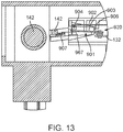
- the biasing force works similarly with the switch in the closed / on position 920, shown in Figure 13 .
- the force would supplement repulsion of the magnets in keeping the arm member 142 and the terminal 901 in the closed / on positon 920.
- the biasing force of the biasing member 967 assists in positioning the moveable member 903 in a downward position.
Landscapes
- Switches Operated By Changes In Physical Conditions (AREA)
- Push-Button Switches (AREA)
- Driving Mechanisms And Operating Circuits Of Arc-Extinguishing High-Tension Switches (AREA)
- Switches That Are Operated By Magnetic Or Electric Fields (AREA)
Description
- There are many types of electrical switches for pumps. With many of these pumps, there is a need for a compact switching module that can reliably and repeatedly turn on and turn off the pump. Some compact switch modules use a sealed arm to actuate a switching mechanism, some use magnets in attraction to a metal plate or that interact with other magnets to actuate a switch, and some use magnets and reed switches to actuate relays. Examples of switches for pump are shown in
WO0057380 US4742195 andUS5155311 . Many of these systems are complex and require the use of springs and other mechanisms that toggle and hold the switches' contacts in closed or open positions. Many of these systems also cause unbiased forces on the actuating members causing wear on sliding members. - For the reasons stated above and for other reasons stated below, which will become apparent to those skilled in the art upon reading and understanding the present specification, there is a need in the art for simpler, more reliable switches.
- The above-mentioned problems associated with prior devices are addressed by embodiments of the present invention and will be understood by reading and understanding the present specification. The following summary is made by way of example and not by way of limitation. It is merely provided to aid the reader in understanding some of the aspects of the invention.
- A activated switch according to the invention is defined in
independent claim 1. Further optional features are set out in the dependent claims. - The present invention can be more easily understood, and further advantages and uses thereof can be more readily apparent, when considered in view of the detailed description and the following Figures in which:
-
Figure 1 is a schematic view of an actuating member and a switch arm illustrating operation of switch activation in accordance with the principles of the present invention; -
Figure 2 is another schematic view of the actuating member and the switch arm shown inFigure 1 illustrating operation of another switch activation in accordance with the principles of the present invention; -
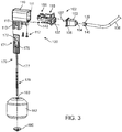
Figure 3 is a partially exploded perspective view of a magnetically activated switch assembly constructed in accordance with the principles of the present invention; -
Figure 3A is an exploded perspective view of a switch assembly of the magnetically activated switch assembly shown inFigure 3 ; -
Figure 3B is a front perspective view of first and second terminals and a base of the switch assembly shown inFigure 3A ; -
Figure 3C is a rear perspective view of first and second terminals and a base of the switch assembly shown inFigure 3A ; -
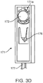
Figure 3D is a rear view of a connecting member of the magnetically activated switch assembly's actuating member shown inFigure 3 ; -
Figure 4 is a side view of the magnetically activated switch assembly shown inFigure 3 in an open / off position; -
Figure 5 is a partial cross section side view of the magnetically activated switch assembly shown inFigure 4 ; -
Figure 5A is a partial cross section of a portion of the magnetically activated switch assembly shown inFigure 3 in an open / off position; -
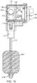
Figure 6 is a cross section view of the magnetically activated switch assembly shown inFigure 4 taken along the lines 6-6; -
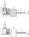
Figure 7 is a side view of the magnetically activated switch assembly shown inFigure 3 in a closed / on position; -
Figure 8 is a partial cross section side view of the magnetically activated switch assembly shown inFigure 7 ; -
Figure 8A is a partial cross section of a portion of the magnetically activated switch assembly shown inFigure 3 in a closed / on position; -
Figure 9 is a cross section view of the magnetically activated switch assembly shown inFigure 7 taken along the lines 9-9; -
Figure 10 is a partial cross section view of another embodiment magnetically activated switch assembly in an open / off position constructed in accordance with the principles of the present invention; -
Figure 11 is a partial cross section view of the magnetically activated switch assembly shown inFigure 10 in a closed / open position; -
Figure 12 is a cross section view of a portion of another embodiment magnetically activated switch assembly in an open / off position constructed in accordance with the principles of the present invention; and -
Figure 13 is a cross section view of the portion of the magnetically activated switch assembly shown inFigure 12 in a closed / open position. - In accordance with common practice, the various described features are not drawn to scale but are drawn to emphasize specific features relevant to the present invention. Reference characters denote like elements throughout the Figures and the text.
- In the following detailed description, reference is made to the accompanying drawings, which form a part hereof, and in which is shown by way of illustration embodiments in which the inventions may be practiced. These embodiments are described in sufficient detail to enable those skilled in the art to practice the invention, and it is to be understood that other embodiments may be utilized and mechanical changes may be made without departing from the scope of the present invention. The following detailed description is, therefore, not to be taken in a limiting sense, and the scope of the present invention is defined only by the claims.
- Embodiments of the present invention provide a magnetically actuated switch.
- The directional terms such as up, upward, down, and downward are being used with reference to the orientations shown in the Figures illustrating examples of embodiments and it is recognized that movement could be in any suitable direction not limited to those described.
- In one embodiment, a magnetically actuated switch includes a magnet on an actuating member in repulsion between two magnet portions on arm portions of the switch. This example embodiment is schematically illustrated in
Figures 1 and 2 . When the actuatingmember 170 of the switch is in the open / off position, for example the position shown inFigure 1 , themagnet 172 of the actuatingmember 170 is in repulsion with themagnet portions arm portions magnet portion 157 includes anorth pole 158 on one side and asouth pole 159 on the other side, themagnet portion 160 includes anorth pole 161 on one side and asouth pole 162 on the other side, and themagnet 172 includes anorth pole 173 on one side and asouth pole 174 on the other side. Themagnet portions center line 164, and themagnet 172 has acenter line 175. One side of the actuating member'smagnet 172 includes thesouth pole 174, which is adjacent thesouth pole 159 of themagnet portion 157 on thearm portion 143 and creates arepulsion force 185, and the other side of the actuating member'smagnet 172 includes thenorth pole 173, which is adjacent thenorth pole 161 of themagnet portion 160 on thearm portion 148 and creates arepulsion force 186. The repulsion forces 185 and 186 of themagnets - When the actuating
member 170 of the switch is in the closed / open position, for example the position shown inFigure 2 , themagnet 172 of the actuatingmember 170 is in repulsion with themagnet portions arms magnets - The magnetically activated switch could be used with any suitable application. An example of a suitable application is a float actuated switch for use with a pump.
- When used with a float actuated switch, a float could be connected to the actuating
member 170. As the liquid level changes, the float moves the actuatingmember 170 upward so that thecenter lines magnet 172 moving upward and themagnet portions - Although a three magnets design is shown and described, it is recognized that two or more magnets could be used, at least one magnet on an actuating member and at least one magnet on an arm member. An advantage to the three magnets design is that the two magnet portions of the arm portions provide forces that keep the magnet of the actuating member between the two magnet portions of the arm portions, which assists in stabilizing movement of the actuating member so that it is not pulled to one side or the other. Because the side to side forces from these magnets counteract each other, this reduces friction on the actuating member and the switch arm portions thereby reducing wear and binding problems.
- In one embodiment, an example of using a three magnets design with a standard electrical switch is illustrated in
Figures 3-9 . A magnetically activatedswitch 100 generally includes aswitch 118 and an actuatingmember 170, which are at least partially contained within ahousing 102. - The
switch 118, shown inFigures 3 and3A , includes abase 119 having a generallysquare plate member 119a about which aflange 124 extends. Theplate member 119a includes a recessed area for receiving aflange 106 of aterminal housing portion 103 proximate one side of theplate member 119a. Theplate member 119a also includes afirst slot 120 and asecond slot 121 positioned within the boundaries of the recessed area. The first andsecond slots second terminals terminals slots wires terminal housing portion 103. A portion of the base 119 extending outward from theplate member 119a includes afirst protrusion 122 and asecond protrusion 123 extending outward laterally proximate the other side of theplate member 119a. Atop extension 125 extends outward from thebase 119 above theprotrusions bottom extension 126 extends outward from theplate member 119a below theprotrusions - A lever or
arm member 142 includes afirst arm portion 143 and asecond arm portion 148 forming achannel 165 therebetween. Thefirst arm portion 143 includes afirst end 144 with anotch 145 that receives thefirst protrusion 122 and asecond end 146 with areceiver 147 that receives afirst portion 157 of afirst magnet 156. Thesecond arm portion 148 includes afirst end 149 with anotch 150 that receives thesecond protrusion 123 and asecond end 151 with areceiver 152 that receives asecond portion 160 of thefirst magnet 156. As shown inFigure 3A , thereceivers first magnet 156 includes thefirst portion 157 having anorth pole 158 and asouth pole 159 and thesecond portion 160 having anorth pole 161 and asouth pole 162. The first andsecond portions center line 164. The first andsecond arm portions respective protrusions connector 154 interconnects thefirst arm portion 143 and thesecond arm portion 148 and selectively engages thefirst terminal 128, as is described in more detail in the following description. - The
first terminal 128 includes afirst end 129, a portion of which extends through thefirst slot 120, and asecond end 130 including acontact 131. As shown inFigure 3A , thesecond end 130 is thinner than thefirst end 129 so that it can flex or deflect more easily. Thesecond terminal 132 includes afirst end 133, a portion of which extends through thesecond slot 121, and asecond end 134 including acontact 135. Thecontacts - A
power cord 138 includes afirst wire 139 and asecond wire 140. Thefirst wire 139 connects to thefirst end 129 of thefirst terminal 128, and thesecond wire 140 connects to thefirst end 133 of thesecond terminal 132. - A lift rod or actuating
member 170 includes a connectingmember 171 to which asecond magnet 172 is connected, and the connectingmember 171 is positioned within thechannel 165 between the first andsecond arm portions Figure 3D , thesecond magnet 172 is held in place via inwardly extendingprotrusions 171a. The second magnet has anorth pole 173 and asouth pole 174 and has acenter line 175. Aprotrusion 176 extends laterally outward from a side of the connectingmember 171, and arod 177 is connected to an end of the connectingmember 171. Therod 177 extends through abore 183 of afloat 182, and astop member 178 is connected to a distal end of therod 177. Thestop member 178 is preferably adjustable along a length of therod 177 to adjust the distance between thestop member 178 and the connectingmember 171 thereby adjusting the distance the float travels along therod 177. Thestop member 178 could be a push onwasher 180 or any other suitable stop member and therod 177 could include at least twoflanges 179 extending outward therefrom to keep thestop member 178 in a desired position on therod 177. - The
housing 102 includes aterminal housing portion 103, aswitch housing portion 110, and arod receiver 113. Theterminal housing portion 103 forms acavity 105 to which abore 104 on one end and anopening 107 on the other end provide access. Aflange 106 extends outwardly from theterminal housing portion 103 about theopening 107 and provides a surface to which the switch base'sflange 124 is connected. Thepower cord 138 extends through thebore 104 and thewires terminals cavity 105. Thecavity 105 is preferably filled with epoxy or other seal substance to assist in securing the connections and providing a seal. This creates a water cut preventing water from traveling along the wires into the switch housing. - The
switch housing portion 110 includes acavity 111 for receiving theswitch 118, and theswitch housing portion 110 and thebottom extension 126 include aligning apertures through which thefasteners 112 extend to interconnect theswitch housing portion 110 and theswitch 118. - The
rod receiver 113 includes acavity 114 in fluid communication with thecavity 111 and includes awindow 115 on one side. Thecavity 111 and thecavity 114 receive a portion of the connectingmember 171, which moves longitudinally within thecavities protrusion 176 of the connectingmember 171 extends through thewindow 115 to provide an easy, snap-in assembly as no additional pins or securing members are needed to hold the connectingmember 171 in place within thecavities cavities - Generally, in this example embodiment, two outer magnets are in repulsion with a center magnet. In the closed / on position, the pivotable arm member is not touching the terminals thereby reducing the chance that vibration from the pump could open the contacts. The arm member can be positioned so that, for the first few degrees of movement (initial movement) of the arm member, it does not touch the terminals. The initial movement of the arm member can be optimized to ensure that optimal force is available to open the contacts / terminals. This initial movement also allows momentum to build up in the arm member that can be used to open the contacts / terminals. If the contacts / terminals of the switch become stuck, the optimization of the magnets strength and the addition of the momentum of the arm member due to its initial movement can be used to move the contacts / terminals.
- In operation, when used with a float and starting with a low liquid level, the actuating
member 170 is in its down position and the repulsion forces hold thearm member 142 in an upward position, which causes theconnector 154 to engage the terminal 128, flexing thesecond end 130 upward. Because thesecond end 130 ofterminal 128 is thinner than thefirst end 129, thesecond end 130 easily flexes or deflects when contacted by theconnector 154 thereby holding the terminal 128 away from the terminal 132 so that therespective contacts Figure 5A , which depicts the switch is in the open / offposition 188. As the liquid level rises, it lifts thefloat 182. Should the liquid level rise high enough, thefloat 182 contacts the connectingmember 171, which moves the actuatingmember 170 upward. - As the actuating member continues to move upward, the repulsion forces increase and continue to force the magnets apart keeping the switch open until the center lines (shown as 164 and 175 in
Figures 1 and 2 ) of the three magnets pass each other. At this time, the net force on the actuating member and the arm portions of the switch are reversed. When this occurs, the reversal of the net force causes the arm portions of the switch to move downward and the actuating member to move upward, due to the increased repulsion forces. Due to the repulsion forces, the actuating member and the arm portions move past each other quickly in a snap-type action. This movement of the actuating member and the arm portions causes theconnector 154 to move away from the terminal 128, allowing thesecond end 130 to move back into position so that thecontact 131 contacts thecontact 135, thereby closing the electrical contacts and turning on the load (e.g., a pump). As shown inFigure 8A , the switch is in the closed / onposition 189. The arm member closes the contacts, and repulsion forces from the magnets assist in holding the arm in its down position, allowing the contacts to remain closed. Thebottom extension 126 acts like a stop for theconnector 154 when the arm portions are in a downward position. - As the liquid level drops, the float moves downward along the
rod 177 with the liquid level. When thefloat 182 contacts thestop member 178, the actuatingmember 170 is pulled downward slowly until the center lines of the magnets align. When this occurs, the actuatingmember 170 and thearm portions terminals arm member 142 pivots upward, theconnector 154 engages thefirst terminal 128 which allows it to move upward away from thesecond terminal 132 so that therespective contacts - The terminal 128 is preferably a leaf spring that keeps the
contacts - The float travels up and down along a rod of the actuating member based on liquid level. When the float reaches the top of the rod proximate the connecting member, the rod moves upward and, when the float reaches the bottom of the rod proximate the stop member, the rod moves downward. The distance the float travels between the top and the bottom could be adjusted. A stop member, such as a push-on washer and at least two flanges extending outwardly from the rod, could be used to adjust the distance the float could travel along the rod thereby allowing the liquid level controlled by the pump to be adjusted. The washer is designed so that it can be is easily pushed up by user to reduce the available float movement but when the float makes contact with the washer it does not easily move down. In other words, the washer moves easily upward along the rod but not easily downward along the rod because of the configurations of the washer and the rod. Any suitable friction member or engaging member could be used as a stop member.
- Many variations of this design could be used. For example, one design variation could include contacts that are biased with a biasing member (e.g., a spring) to assist in keeping the switch in an open position or a closed position even when the actuating member is not acting on the switch arm. Other design variations could include having the switch arm used to actuate a plunger type switch or a lever type switch of a standard electrical switch. All of these designs could still use the principle of using magnets, for example, a magnet of an actuating member in repulsion between at least one magnet of a switch arm. When the magnets move past each other, this movement opens and closes the contacts of the switch. Although three magnets are preferred, it is recognized that two or more magnets in repulsion could be used.
- The use of a float and an actuating member (e.g., lift rod) is illustrated as an embodiment of the invention in the Figures, but it is recognized that the actuating member could be replaced with other suitable members including a pivoting arm, a sliding member, a rotating member, a flexing member, or a bending member.
- The switch arm of the switch is illustrated as an embodiment of the invention in the Figures as a pivoting arm, but it is recognized that the switch could be replaced with other sliding, rotating, flexing, or bending members.
- Further, it is recognized that the present invention is not limited to use with a float actuated switch and could be utilized in different applications.
-
Figures 10 and11 illustrate another embodiment magnetically activated switch. This embodiment is similar to the magnetically activatedswitch 100 and, therefore, only the significant differences are being described. The same reference numerals are used for some of the common components. - Rather than being positioned generally below the
terminals terminals terminal 132. Alternative types of a float 182' and a stop member 178' that could be used are shown. - Another embodiment is shown in
Figures 12 and13 . As illustrated in this embodiment, one of the terminals could be made from two pieces. For example, a terminal 901 could include astationary member 902 and amovable member 903, which pivots about apivot point 904 where the two members are connected. Optionally, biasingmember 967 could interconnect the terminal 901 and thearm member 142 to place a biasing force on thearm member 142. The biasingmember 967 could be connected to the terminal 901 at aconnection 906 proximate a distal end of themovable member 903 and could be connected to thearm member 142 atlocation 907 by any suitable connecting means, such as an aperture in one component through which a wire or a pin connected to the other component extends. The biasing force could supplement the repulsion forces of the magnets in keeping thearm member 142 and the terminal 901 in the open / offposition 910, shown inFigure 12 . For example, when thearm member 142 is in an upward position relative to the magnet of the actuating member (not shown inFigures 12 and13 ), the biasing force of the biasingmember 967 assists in positioning themovable member 903 in an upward position. The biasing force works similarly with the switch in the closed / onposition 920, shown inFigure 13 . The force would supplement repulsion of the magnets in keeping thearm member 142 and the terminal 901 in the closed / onpositon 920. For example, when thearm member 142 is in a downward position relative to the magnet of the actuating member (not shown inFigures 12 and13 ), the biasing force of the biasingmember 967 assists in positioning themoveable member 903 in a downward position. - Although the present invention has been described for operation of a pump or other liquid level control device, but it is recognized that the present invention could be utilized for any mechanism activated with movement of an actuating member.
- The above specification, examples, and data provide a complete description of the manufacture and use of the composition of embodiments of the invention. Although specific embodiments have been illustrated and described herein, it will be appreciated by those of ordinary skill in the art that any arrangement, which is calculated to achieve the same purpose, may be substituted for the specific embodiment shown. Therefore, it is manifestly intended that this invention be limited only by the claims.
Claims (8)
- A magnetically activated switch (100), comprising:an arm member (142, 142') having a first magnet (156);an actuating member (170) having a second magnet (172), the actuating member (170) being configured and arranged to move relative to the arm member (142, 142') thereby moving the second magnet (172) relative to the first magnet (156), the second magnet (172) having a repulsion force to the first magnet (156); anda switch having a contact, wherein movement of the second magnet (172) in a first direction past the first magnet (156) positions the contact in an open position and movement of the second magnet in a second direction past the first magnet (156) positions the contact in a closed position;characterized in that the first magnet (156) includes a first magnet portion (157) and a second magnet portion (160, 160') spaced apart to form a channel (165) through which the second magnet (172) moves, and in that the second magnet (172) has a north pole (173) on a first side and a south pole (174) on a second side, the second magnet portion (160, 160') having a north pole (161) on a side adjacent the first side of the second magnet (172) and the first magnet portion (157) having a south pole (159) on a side adjacent the second side of the second magnet (172) when the second magnet (172) is moving through the channel (165),wherein the first and second magnets (156, 172) cause the arm member (142, 142') and the actuating member (170) to move in opposite directions relative to one another, movement of the arm member (142, 142') and the actuating member (170) in first opposite directions position the contact in the open position, and movement of the arm member (142, 142') and the actuating member (170) in second opposite directions position the contact in the closed position.
- The magnetically activated switch (100) of claim 1, wherein the arm member (142, 142') includes a first arm portion (143) to which the first magnet portion (157) is connected and a second arm portion (148, 148') to which the second magnet portion (160, 160') is connected, the first and second arm portions being spaced apart to form the channel (165) through which the actuating member (170) moves.
- The magnetically activated switch (100) of claim 1, further comprising a float operatively connected to the actuating member (170), wherein change in a liquid level in which the float is positioned causes the float to move the actuating member (170) relative to the arm member (142, 142').
- The magnetically activated switch (100) of claim 3, wherein the actuating member (170) includes a rod (177) along which the float moves.
- The magnetically activated switch (100) of claim 4, wherein the rod includes a stop member (178) movable along a length of the rod (177) to vary a distance the float moves along the rod (177).
- The magnetically activated switch (100) of claim 1, wherein the arm member (142, 142') is a lever of an electrical switch.
- The magnetically activated switch (100) of claim 1, further comprising a spring placing a biasing force on the switch to assist in positioning the contact in the open and closed positions.
- The magnetically activated switch (100) of claim 1, wherein the actuating member (170) is selected from the group consisting of a pivoting arm, a sliding member, a rotating member, a flexing member, or a bending member.
Applications Claiming Priority (4)
| Application Number | Priority Date | Filing Date | Title |
|---|---|---|---|
| US201662300480P | 2016-02-26 | 2016-02-26 | |
| US201662350425P | 2016-06-15 | 2016-06-15 | |
| US15/429,904 US10141141B2 (en) | 2016-02-26 | 2017-02-10 | Magnetically actuated switch |
| PCT/US2017/017628 WO2017146929A1 (en) | 2016-02-26 | 2017-02-13 | Magnetically actuated switch |
Publications (2)
| Publication Number | Publication Date |
|---|---|
| EP3420573A1 EP3420573A1 (en) | 2019-01-02 |
| EP3420573B1 true EP3420573B1 (en) | 2020-08-19 |
Family
ID=59679040
Family Applications (1)
| Application Number | Title | Priority Date | Filing Date |
|---|---|---|---|
| EP17708029.8A Active EP3420573B1 (en) | 2016-02-26 | 2017-02-13 | Magnetically actuated switch |
Country Status (6)
| Country | Link |
|---|---|
| US (1) | US10141141B2 (en) |
| EP (1) | EP3420573B1 (en) |
| CN (1) | CN108604513B (en) |
| CA (1) | CA3011555C (en) |
| MX (1) | MX386795B (en) |
| WO (1) | WO2017146929A1 (en) |
Families Citing this family (9)
| Publication number | Priority date | Publication date | Assignee | Title |
|---|---|---|---|---|
| US10550845B2 (en) | 2015-07-22 | 2020-02-04 | S. J. Electro Systems, Inc. | Liquid level sensing system |
| USD818441S1 (en) * | 2016-11-14 | 2018-05-22 | S.J. Electro Systems, Inc. | Float switch housing |
| CN109719799B (en) * | 2017-10-30 | 2022-04-26 | 南京泉峰科技有限公司 | a chain saw |
| US20190234397A1 (en) * | 2018-02-01 | 2019-08-01 | Gp Enterprises Co., Ltd | Vertical-Shaft Sewage Pump with Anti-Collision Switch |
| CN109399210B (en) * | 2018-11-14 | 2020-06-05 | 湖南真创环保科技有限公司 | Liquid buoyancy conveying heavy object falling device |
| CN109216105B (en) * | 2018-11-14 | 2020-04-07 | 湖南真创环保科技有限公司 | Schmidt hydraulic control switch |
| CN109300736B (en) * | 2018-11-14 | 2020-01-10 | 湖南真创环保科技有限公司 | Device for hanging and releasing heavy object |
| US11094486B2 (en) | 2018-12-20 | 2021-08-17 | Cognex Corporation | Magnetic trigger arrangement |
| US11657992B2 (en) | 2019-05-06 | 2023-05-23 | Jeffrey A. Stallmer | Protective cover assembly for magnetically actuating an electrical wall switch |
Family Cites Families (43)
| Publication number | Priority date | Publication date | Assignee | Title |
|---|---|---|---|---|
| US2777914A (en) * | 1953-10-08 | 1957-01-15 | Reliance Gauge Column Company | Magnetic switch |
| US3022397A (en) * | 1959-12-11 | 1962-02-20 | Reliance Gauge Column Co | Liquid level indicator |
| US3013135A (en) * | 1960-05-06 | 1961-12-12 | John R Russo | Magnetic float control |
| US3541283A (en) * | 1968-09-27 | 1970-11-17 | August Milo | Leak detector for pumped liquid systems |
| US3632925A (en) * | 1968-11-18 | 1972-01-04 | Katsuji Fujiwara | Float responsive switch unit |
| US3602665A (en) * | 1969-02-07 | 1971-08-31 | Acme Divac Ind Inc | Control device and barrier bag therefor |
| US3588404A (en) * | 1969-05-09 | 1971-06-28 | Simmonds Precision Products | Magnetic float reed switch point sensor |
| US3659064A (en) * | 1970-09-05 | 1972-04-25 | Cdm Co Ltd | Water surface switch |
| GB1388845A (en) * | 1971-07-21 | 1975-03-26 | Trist Controls Ltd Ronald | Magnet switch for liquid containers |
| GB1460171A (en) * | 1974-03-25 | 1976-12-31 | Bestobell Mobrey Ltd | Magnetically operated switch unit |
| US4066858A (en) * | 1975-11-17 | 1978-01-03 | International Telephone And Telegraph Corporation | Vertical float switch |
| US4142079A (en) * | 1978-02-09 | 1979-02-27 | Delaval Turbine Inc. | Float-level switch with lifting mechanism |
| US4186419A (en) * | 1978-11-20 | 1980-01-29 | Sims Bobby H | Apparatus for monitoring and controlling liquid level |
| US4481389A (en) * | 1982-08-02 | 1984-11-06 | Liquid Level Lectronics, Inc. | Magnetic control device |
| US4647740A (en) * | 1985-01-28 | 1987-03-03 | Hansen Technologies Corp. | Float switch assembly for refrigeration system |
| US4836239A (en) | 1985-03-25 | 1989-06-06 | Kinkead Clifford W | Water cooling tower and water level control system therefor |
| CA1227987A (en) * | 1985-04-19 | 1987-10-13 | Garland Commercial Ranges Limited | Float valve control |
| US4742195A (en) | 1985-12-02 | 1988-05-03 | Magnetrol International Incorporated | High temperature hermetic switch |
| US4788534A (en) * | 1986-06-06 | 1988-11-29 | Bernard Engelhardt | Wind alarm sensor |
| US5042300A (en) * | 1986-11-03 | 1991-08-27 | Kelsey-Hayes Company | Liquid level sensor |
| US4943210A (en) | 1988-10-03 | 1990-07-24 | Bailey Jr James R | Pump control system, level sensor switch and switch housing |
| US5030803A (en) * | 1989-08-07 | 1991-07-09 | General Dynamics Corp., Air Defense Systems Div. | Offset float switch |
| US5141404A (en) | 1990-06-25 | 1992-08-25 | Q.E.D. Environmental Systems, Inc. | Pump apparatus |
| US5262604A (en) * | 1991-04-05 | 1993-11-16 | The United States Of America As Represented By The United States Department Of Energy | Float level switch for a nuclear power plant containment vessel |
| US5155311A (en) | 1991-07-03 | 1992-10-13 | S.J. Electro Systems, Inc. | Float switch assembly for submersible pump |
| GB2263580B (en) * | 1992-01-17 | 1996-02-14 | Hamlin Electronics Europ Ltd | A switch assembly |
| US5294917A (en) | 1992-04-06 | 1994-03-15 | Wilkins Larry C | Liquid level sensor using float and magnetic means |
| US5324171A (en) | 1993-05-14 | 1994-06-28 | Liberty Pumps | Pump assembly including a hermetically sealed switch capsule for housing a magnetically actuated switch |
| EP0662569A1 (en) | 1994-01-10 | 1995-07-12 | Iwao Ikegami | Brake apparatus |
| DE9413499U1 (en) * | 1994-08-22 | 1994-10-27 | Unimeß Meßtechnische Geräte GmbH, 61239 Ober-Mörlen | Level measuring device, in particular overfill protection for a liquid tank |
| US5562422A (en) | 1994-09-30 | 1996-10-08 | Goulds Pumps, Incorporated | Liquid level control assembly for pumps |
| US5629659A (en) * | 1995-10-31 | 1997-05-13 | Steiner; George A. | Single switching of magnetic reed switch |
| US6069331A (en) * | 1998-04-24 | 2000-05-30 | Utke; Gene H. | Flow control vertical switch |
| US6140925A (en) | 1999-03-19 | 2000-10-31 | S. J. Electro Systems, Inc. | Magnetically actuated float switch |
| US6246307B1 (en) * | 2000-05-19 | 2001-06-12 | The United States Of America As Represented By The Secretary Of The Army | Magnetic switch |
| US6528748B2 (en) * | 2001-06-05 | 2003-03-04 | Gp Companies, Inc. | In-line flow switch assembly including magnetic sensitive plunger and microswitch actuator |
| US7113063B2 (en) * | 2002-03-18 | 2006-09-26 | Cellnet Innovations, Inc. | Rotation sensing |
| US7015782B2 (en) | 2003-02-19 | 2006-03-21 | Sensys Medical, Inc. | Magneto-mechanical apparatus |
| GB0515067D0 (en) | 2005-07-22 | 2005-08-31 | South Bank Univ Entpr Ltd | Liquid cut-off device |
| US20100129232A1 (en) | 2008-11-24 | 2010-05-27 | Keener Robert M | Float device for a sewage pump |
| CN101656169B (en) * | 2009-08-04 | 2012-11-28 | 苏州优德通力电气有限公司 | Float switch |
| US9046190B1 (en) * | 2011-03-17 | 2015-06-02 | Kenco International, Inc. | Block and bleed valve with a magnetic coupled switch |
| US20150332882A1 (en) * | 2014-05-14 | 2015-11-19 | S.J. Electro Systems, Inc. | High Temperature Float Switch System |
-
2017
- 2017-02-10 US US15/429,904 patent/US10141141B2/en active Active
- 2017-02-13 CN CN201780010335.3A patent/CN108604513B/en active Active
- 2017-02-13 MX MX2018010303A patent/MX386795B/en unknown
- 2017-02-13 EP EP17708029.8A patent/EP3420573B1/en active Active
- 2017-02-13 WO PCT/US2017/017628 patent/WO2017146929A1/en not_active Ceased
- 2017-02-13 CA CA3011555A patent/CA3011555C/en active Active
Non-Patent Citations (1)
| Title |
|---|
| None * |
Also Published As
| Publication number | Publication date |
|---|---|
| US20170250041A1 (en) | 2017-08-31 |
| US10141141B2 (en) | 2018-11-27 |
| CA3011555C (en) | 2023-08-08 |
| CN108604513B (en) | 2020-05-15 |
| WO2017146929A1 (en) | 2017-08-31 |
| CN108604513A (en) | 2018-09-28 |
| MX386795B (en) | 2025-03-19 |
| CA3011555A1 (en) | 2017-08-31 |
| EP3420573A1 (en) | 2019-01-02 |
Similar Documents
| Publication | Publication Date | Title |
|---|---|---|
| US10141141B2 (en) | Magnetically actuated switch | |
| EP0347999A2 (en) | Electric switch structure in which the actuation axial force is just a small portion of the contact force | |
| US9013084B2 (en) | Induction generator | |
| EP3166121B1 (en) | Electrical pushbutton switch | |
| US8222981B1 (en) | Electrical switching device | |
| KR850003241Y1 (en) | Electromagnetic valve | |
| GB2394602A (en) | Relay | |
| US8115131B2 (en) | Electrical pushbutton snap switch | |
| CA2060748A1 (en) | Float switch assembly | |
| US10290449B2 (en) | Electric switch | |
| EP2551870B1 (en) | Electromagnetic relay | |
| CA2694446A1 (en) | Magnetically actuated float switch | |
| US6091038A (en) | Electrical switch with sliding terminal contacts | |
| SK287728B6 (en) | Electromechanical remote switch | |
| WO2017141089A1 (en) | A push button operated switch with anti-jamming guiding system | |
| KR920003352A (en) | Slide selector switch mechanism | |
| EP3312861A1 (en) | Electrical pushbutton snap switch with means for identifying the position of the pushbutton and/or of the driving member | |
| US4636597A (en) | Electrical snap switch | |
| US5172086A (en) | Remotely controlled relay | |
| US3261937A (en) | Three position snap switch utilizing interference blade means | |
| US3052774A (en) | Switch construction | |
| EP0758133A2 (en) | Precision double-pole single-throw switch assembly | |
| EP3166118A1 (en) | Switch | |
| US9355795B2 (en) | M-blade actuated switch assembly | |
| EP3582242B1 (en) | Electrical switch device |
Legal Events
| Date | Code | Title | Description |
|---|---|---|---|
| STAA | Information on the status of an ep patent application or granted ep patent |
Free format text: STATUS: UNKNOWN |
|
| STAA | Information on the status of an ep patent application or granted ep patent |
Free format text: STATUS: THE INTERNATIONAL PUBLICATION HAS BEEN MADE |
|
| PUAI | Public reference made under article 153(3) epc to a published international application that has entered the european phase |
Free format text: ORIGINAL CODE: 0009012 |
|
| STAA | Information on the status of an ep patent application or granted ep patent |
Free format text: STATUS: REQUEST FOR EXAMINATION WAS MADE |
|
| 17P | Request for examination filed |
Effective date: 20180803 |
|
| AK | Designated contracting states |
Kind code of ref document: A1 Designated state(s): AL AT BE BG CH CY CZ DE DK EE ES FI FR GB GR HR HU IE IS IT LI LT LU LV MC MK MT NL NO PL PT RO RS SE SI SK SM TR |
|
| AX | Request for extension of the european patent |
Extension state: BA ME |
|
| DAV | Request for validation of the european patent (deleted) | ||
| DAX | Request for extension of the european patent (deleted) | ||
| STAA | Information on the status of an ep patent application or granted ep patent |
Free format text: STATUS: EXAMINATION IS IN PROGRESS |
|
| 17Q | First examination report despatched |
Effective date: 20190930 |
|
| GRAP | Despatch of communication of intention to grant a patent |
Free format text: ORIGINAL CODE: EPIDOSNIGR1 |
|
| STAA | Information on the status of an ep patent application or granted ep patent |
Free format text: STATUS: GRANT OF PATENT IS INTENDED |
|
| INTG | Intention to grant announced |
Effective date: 20200309 |
|
| GRAS | Grant fee paid |
Free format text: ORIGINAL CODE: EPIDOSNIGR3 |
|
| GRAA | (expected) grant |
Free format text: ORIGINAL CODE: 0009210 |
|
| STAA | Information on the status of an ep patent application or granted ep patent |
Free format text: STATUS: THE PATENT HAS BEEN GRANTED |
|
| AK | Designated contracting states |
Kind code of ref document: B1 Designated state(s): AL AT BE BG CH CY CZ DE DK EE ES FI FR GB GR HR HU IE IS IT LI LT LU LV MC MK MT NL NO PL PT RO RS SE SI SK SM TR |
|
| REG | Reference to a national code |
Ref country code: CH Ref legal event code: EP |
|
| REG | Reference to a national code |
Ref country code: DE Ref legal event code: R096 Ref document number: 602017021908 Country of ref document: DE |
|
| REG | Reference to a national code |
Ref country code: AT Ref legal event code: REF Ref document number: 1304894 Country of ref document: AT Kind code of ref document: T Effective date: 20200915 |
|
| REG | Reference to a national code |
Ref country code: IE Ref legal event code: FG4D |
|
| REG | Reference to a national code |
Ref country code: LT Ref legal event code: MG4D |
|
| REG | Reference to a national code |
Ref country code: NL Ref legal event code: MP Effective date: 20200819 |
|
| PG25 | Lapsed in a contracting state [announced via postgrant information from national office to epo] |
Ref country code: BG Free format text: LAPSE BECAUSE OF FAILURE TO SUBMIT A TRANSLATION OF THE DESCRIPTION OR TO PAY THE FEE WITHIN THE PRESCRIBED TIME-LIMIT Effective date: 20201119 Ref country code: NO Free format text: LAPSE BECAUSE OF FAILURE TO SUBMIT A TRANSLATION OF THE DESCRIPTION OR TO PAY THE FEE WITHIN THE PRESCRIBED TIME-LIMIT Effective date: 20201119 Ref country code: HR Free format text: LAPSE BECAUSE OF FAILURE TO SUBMIT A TRANSLATION OF THE DESCRIPTION OR TO PAY THE FEE WITHIN THE PRESCRIBED TIME-LIMIT Effective date: 20200819 Ref country code: SE Free format text: LAPSE BECAUSE OF FAILURE TO SUBMIT A TRANSLATION OF THE DESCRIPTION OR TO PAY THE FEE WITHIN THE PRESCRIBED TIME-LIMIT Effective date: 20200819 Ref country code: GR Free format text: LAPSE BECAUSE OF FAILURE TO SUBMIT A TRANSLATION OF THE DESCRIPTION OR TO PAY THE FEE WITHIN THE PRESCRIBED TIME-LIMIT Effective date: 20201120 Ref country code: FI Free format text: LAPSE BECAUSE OF FAILURE TO SUBMIT A TRANSLATION OF THE DESCRIPTION OR TO PAY THE FEE WITHIN THE PRESCRIBED TIME-LIMIT Effective date: 20200819 Ref country code: LT Free format text: LAPSE BECAUSE OF FAILURE TO SUBMIT A TRANSLATION OF THE DESCRIPTION OR TO PAY THE FEE WITHIN THE PRESCRIBED TIME-LIMIT Effective date: 20200819 Ref country code: PT Free format text: LAPSE BECAUSE OF FAILURE TO SUBMIT A TRANSLATION OF THE DESCRIPTION OR TO PAY THE FEE WITHIN THE PRESCRIBED TIME-LIMIT Effective date: 20201221 |
|
| REG | Reference to a national code |
Ref country code: AT Ref legal event code: MK05 Ref document number: 1304894 Country of ref document: AT Kind code of ref document: T Effective date: 20200819 |
|
| PG25 | Lapsed in a contracting state [announced via postgrant information from national office to epo] |
Ref country code: IS Free format text: LAPSE BECAUSE OF FAILURE TO SUBMIT A TRANSLATION OF THE DESCRIPTION OR TO PAY THE FEE WITHIN THE PRESCRIBED TIME-LIMIT Effective date: 20201219 Ref country code: LV Free format text: LAPSE BECAUSE OF FAILURE TO SUBMIT A TRANSLATION OF THE DESCRIPTION OR TO PAY THE FEE WITHIN THE PRESCRIBED TIME-LIMIT Effective date: 20200819 Ref country code: RS Free format text: LAPSE BECAUSE OF FAILURE TO SUBMIT A TRANSLATION OF THE DESCRIPTION OR TO PAY THE FEE WITHIN THE PRESCRIBED TIME-LIMIT Effective date: 20200819 Ref country code: NL Free format text: LAPSE BECAUSE OF FAILURE TO SUBMIT A TRANSLATION OF THE DESCRIPTION OR TO PAY THE FEE WITHIN THE PRESCRIBED TIME-LIMIT Effective date: 20200819 Ref country code: PL Free format text: LAPSE BECAUSE OF FAILURE TO SUBMIT A TRANSLATION OF THE DESCRIPTION OR TO PAY THE FEE WITHIN THE PRESCRIBED TIME-LIMIT Effective date: 20200819 |
|
| PG25 | Lapsed in a contracting state [announced via postgrant information from national office to epo] |
Ref country code: SM Free format text: LAPSE BECAUSE OF FAILURE TO SUBMIT A TRANSLATION OF THE DESCRIPTION OR TO PAY THE FEE WITHIN THE PRESCRIBED TIME-LIMIT Effective date: 20200819 Ref country code: EE Free format text: LAPSE BECAUSE OF FAILURE TO SUBMIT A TRANSLATION OF THE DESCRIPTION OR TO PAY THE FEE WITHIN THE PRESCRIBED TIME-LIMIT Effective date: 20200819 Ref country code: CZ Free format text: LAPSE BECAUSE OF FAILURE TO SUBMIT A TRANSLATION OF THE DESCRIPTION OR TO PAY THE FEE WITHIN THE PRESCRIBED TIME-LIMIT Effective date: 20200819 Ref country code: DK Free format text: LAPSE BECAUSE OF FAILURE TO SUBMIT A TRANSLATION OF THE DESCRIPTION OR TO PAY THE FEE WITHIN THE PRESCRIBED TIME-LIMIT Effective date: 20200819 Ref country code: RO Free format text: LAPSE BECAUSE OF FAILURE TO SUBMIT A TRANSLATION OF THE DESCRIPTION OR TO PAY THE FEE WITHIN THE PRESCRIBED TIME-LIMIT Effective date: 20200819 |
|
| REG | Reference to a national code |
Ref country code: DE Ref legal event code: R097 Ref document number: 602017021908 Country of ref document: DE |
|
| PG25 | Lapsed in a contracting state [announced via postgrant information from national office to epo] |
Ref country code: ES Free format text: LAPSE BECAUSE OF FAILURE TO SUBMIT A TRANSLATION OF THE DESCRIPTION OR TO PAY THE FEE WITHIN THE PRESCRIBED TIME-LIMIT Effective date: 20200819 Ref country code: AL Free format text: LAPSE BECAUSE OF FAILURE TO SUBMIT A TRANSLATION OF THE DESCRIPTION OR TO PAY THE FEE WITHIN THE PRESCRIBED TIME-LIMIT Effective date: 20200819 Ref country code: AT Free format text: LAPSE BECAUSE OF FAILURE TO SUBMIT A TRANSLATION OF THE DESCRIPTION OR TO PAY THE FEE WITHIN THE PRESCRIBED TIME-LIMIT Effective date: 20200819 |
|
| PLBE | No opposition filed within time limit |
Free format text: ORIGINAL CODE: 0009261 |
|
| STAA | Information on the status of an ep patent application or granted ep patent |
Free format text: STATUS: NO OPPOSITION FILED WITHIN TIME LIMIT |
|
| PG25 | Lapsed in a contracting state [announced via postgrant information from national office to epo] |
Ref country code: SK Free format text: LAPSE BECAUSE OF FAILURE TO SUBMIT A TRANSLATION OF THE DESCRIPTION OR TO PAY THE FEE WITHIN THE PRESCRIBED TIME-LIMIT Effective date: 20200819 |
|
| 26N | No opposition filed |
Effective date: 20210520 |
|
| PG25 | Lapsed in a contracting state [announced via postgrant information from national office to epo] |
Ref country code: SI Free format text: LAPSE BECAUSE OF FAILURE TO SUBMIT A TRANSLATION OF THE DESCRIPTION OR TO PAY THE FEE WITHIN THE PRESCRIBED TIME-LIMIT Effective date: 20200819 |
|
| REG | Reference to a national code |
Ref country code: DE Ref legal event code: R119 Ref document number: 602017021908 Country of ref document: DE |
|
| PG25 | Lapsed in a contracting state [announced via postgrant information from national office to epo] |
Ref country code: MC Free format text: LAPSE BECAUSE OF FAILURE TO SUBMIT A TRANSLATION OF THE DESCRIPTION OR TO PAY THE FEE WITHIN THE PRESCRIBED TIME-LIMIT Effective date: 20200819 |
|
| GBPC | Gb: european patent ceased through non-payment of renewal fee |
Effective date: 20210213 |
|
| REG | Reference to a national code |
Ref country code: BE Ref legal event code: MM Effective date: 20210228 |
|
| PG25 | Lapsed in a contracting state [announced via postgrant information from national office to epo] |
Ref country code: CH Free format text: LAPSE BECAUSE OF NON-PAYMENT OF DUE FEES Effective date: 20210228 Ref country code: LU Free format text: LAPSE BECAUSE OF NON-PAYMENT OF DUE FEES Effective date: 20210213 Ref country code: LI Free format text: LAPSE BECAUSE OF NON-PAYMENT OF DUE FEES Effective date: 20210228 |
|
| PG25 | Lapsed in a contracting state [announced via postgrant information from national office to epo] |
Ref country code: GB Free format text: LAPSE BECAUSE OF NON-PAYMENT OF DUE FEES Effective date: 20210213 Ref country code: IE Free format text: LAPSE BECAUSE OF NON-PAYMENT OF DUE FEES Effective date: 20210213 Ref country code: DE Free format text: LAPSE BECAUSE OF NON-PAYMENT OF DUE FEES Effective date: 20210901 |
|
| PG25 | Lapsed in a contracting state [announced via postgrant information from national office to epo] |
Ref country code: BE Free format text: LAPSE BECAUSE OF NON-PAYMENT OF DUE FEES Effective date: 20210228 |
|
| PG25 | Lapsed in a contracting state [announced via postgrant information from national office to epo] |
Ref country code: CY Free format text: LAPSE BECAUSE OF FAILURE TO SUBMIT A TRANSLATION OF THE DESCRIPTION OR TO PAY THE FEE WITHIN THE PRESCRIBED TIME-LIMIT Effective date: 20200819 |
|
| P01 | Opt-out of the competence of the unified patent court (upc) registered |
Effective date: 20230529 |
|
| PG25 | Lapsed in a contracting state [announced via postgrant information from national office to epo] |
Ref country code: HU Free format text: LAPSE BECAUSE OF FAILURE TO SUBMIT A TRANSLATION OF THE DESCRIPTION OR TO PAY THE FEE WITHIN THE PRESCRIBED TIME-LIMIT; INVALID AB INITIO Effective date: 20170213 |
|
| PG25 | Lapsed in a contracting state [announced via postgrant information from national office to epo] |
Ref country code: MK Free format text: LAPSE BECAUSE OF FAILURE TO SUBMIT A TRANSLATION OF THE DESCRIPTION OR TO PAY THE FEE WITHIN THE PRESCRIBED TIME-LIMIT Effective date: 20200819 |
|
| PG25 | Lapsed in a contracting state [announced via postgrant information from national office to epo] |
Ref country code: TR Free format text: LAPSE BECAUSE OF FAILURE TO SUBMIT A TRANSLATION OF THE DESCRIPTION OR TO PAY THE FEE WITHIN THE PRESCRIBED TIME-LIMIT Effective date: 20200819 |
|
| PG25 | Lapsed in a contracting state [announced via postgrant information from national office to epo] |
Ref country code: MT Free format text: LAPSE BECAUSE OF FAILURE TO SUBMIT A TRANSLATION OF THE DESCRIPTION OR TO PAY THE FEE WITHIN THE PRESCRIBED TIME-LIMIT Effective date: 20200819 |
|
| PGFP | Annual fee paid to national office [announced via postgrant information from national office to epo] |
Ref country code: IT Payment date: 20260210 Year of fee payment: 10 |
|
| PGFP | Annual fee paid to national office [announced via postgrant information from national office to epo] |
Ref country code: FR Payment date: 20260218 Year of fee payment: 10 |