EP3420664B1 - Procédé et appareil pour fournir différents services dans un système de communication mobile - Google Patents
Procédé et appareil pour fournir différents services dans un système de communication mobile Download PDFInfo
- Publication number
- EP3420664B1 EP3420664B1 EP17775928.9A EP17775928A EP3420664B1 EP 3420664 B1 EP3420664 B1 EP 3420664B1 EP 17775928 A EP17775928 A EP 17775928A EP 3420664 B1 EP3420664 B1 EP 3420664B1
- Authority
- EP
- European Patent Office
- Prior art keywords
- terminal
- information
- data
- resources
- base station
- Prior art date
- Legal status (The legal status is an assumption and is not a legal conclusion. Google has not performed a legal analysis and makes no representation as to the accuracy of the status listed.)
- Active
Links
Images






Classifications
-
- H—ELECTRICITY
- H04—ELECTRIC COMMUNICATION TECHNIQUE
- H04L—TRANSMISSION OF DIGITAL INFORMATION, e.g. TELEGRAPHIC COMMUNICATION
- H04L5/00—Arrangements affording multiple use of the transmission path
- H04L5/0001—Arrangements for dividing the transmission path
- H04L5/0003—Two-dimensional division
- H04L5/0005—Time-frequency
-
- H—ELECTRICITY
- H04—ELECTRIC COMMUNICATION TECHNIQUE
- H04L—TRANSMISSION OF DIGITAL INFORMATION, e.g. TELEGRAPHIC COMMUNICATION
- H04L1/00—Arrangements for detecting or preventing errors in the information received
- H04L1/20—Arrangements for detecting or preventing errors in the information received using signal quality detector
- H04L1/203—Details of error rate determination, e.g. BER, FER or WER
-
- G—PHYSICS
- G01—MEASURING; TESTING
- G01S—RADIO DIRECTION-FINDING; RADIO NAVIGATION; DETERMINING DISTANCE OR VELOCITY BY USE OF RADIO WAVES; LOCATING OR PRESENCE-DETECTING BY USE OF THE REFLECTION OR RERADIATION OF RADIO WAVES; ANALOGOUS ARRANGEMENTS USING OTHER WAVES
- G01S5/00—Position-fixing by co-ordinating two or more direction or position line determinations; Position-fixing by co-ordinating two or more distance determinations
- G01S5/02—Position-fixing by co-ordinating two or more direction or position line determinations; Position-fixing by co-ordinating two or more distance determinations using radio waves
- G01S5/0284—Relative positioning
-
- H—ELECTRICITY
- H04—ELECTRIC COMMUNICATION TECHNIQUE
- H04L—TRANSMISSION OF DIGITAL INFORMATION, e.g. TELEGRAPHIC COMMUNICATION
- H04L1/00—Arrangements for detecting or preventing errors in the information received
-
- H—ELECTRICITY
- H04—ELECTRIC COMMUNICATION TECHNIQUE
- H04L—TRANSMISSION OF DIGITAL INFORMATION, e.g. TELEGRAPHIC COMMUNICATION
- H04L1/00—Arrangements for detecting or preventing errors in the information received
- H04L1/004—Arrangements for detecting or preventing errors in the information received by using forward error control
- H04L1/0045—Arrangements at the receiver end
- H04L1/0047—Decoding adapted to other signal detection operation
-
- H—ELECTRICITY
- H04—ELECTRIC COMMUNICATION TECHNIQUE
- H04L—TRANSMISSION OF DIGITAL INFORMATION, e.g. TELEGRAPHIC COMMUNICATION
- H04L1/00—Arrangements for detecting or preventing errors in the information received
- H04L1/004—Arrangements for detecting or preventing errors in the information received by using forward error control
- H04L1/0056—Systems characterized by the type of code used
- H04L1/0067—Rate matching
- H04L1/0068—Rate matching by puncturing
-
- H—ELECTRICITY
- H04—ELECTRIC COMMUNICATION TECHNIQUE
- H04L—TRANSMISSION OF DIGITAL INFORMATION, e.g. TELEGRAPHIC COMMUNICATION
- H04L1/00—Arrangements for detecting or preventing errors in the information received
- H04L1/12—Arrangements for detecting or preventing errors in the information received by using return channel
- H04L1/16—Arrangements for detecting or preventing errors in the information received by using return channel in which the return channel carries supervisory signals, e.g. repetition request signals
- H04L1/18—Automatic repetition systems, e.g. Van Duuren systems
- H04L1/1812—Hybrid protocols; Hybrid automatic repeat request [HARQ]
-
- H—ELECTRICITY
- H04—ELECTRIC COMMUNICATION TECHNIQUE
- H04L—TRANSMISSION OF DIGITAL INFORMATION, e.g. TELEGRAPHIC COMMUNICATION
- H04L41/00—Arrangements for maintenance, administration or management of data switching networks, e.g. of packet switching networks
- H04L41/08—Configuration management of networks or network elements
- H04L41/085—Retrieval of network configuration; Tracking network configuration history
- H04L41/0853—Retrieval of network configuration; Tracking network configuration history by actively collecting configuration information or by backing up configuration information
-
- H—ELECTRICITY
- H04—ELECTRIC COMMUNICATION TECHNIQUE
- H04L—TRANSMISSION OF DIGITAL INFORMATION, e.g. TELEGRAPHIC COMMUNICATION
- H04L43/00—Arrangements for monitoring or testing data switching networks
- H04L43/08—Monitoring or testing based on specific metrics, e.g. QoS, energy consumption or environmental parameters
- H04L43/0852—Delays
- H04L43/0864—Round trip delays
-
- H—ELECTRICITY
- H04—ELECTRIC COMMUNICATION TECHNIQUE
- H04L—TRANSMISSION OF DIGITAL INFORMATION, e.g. TELEGRAPHIC COMMUNICATION
- H04L5/00—Arrangements affording multiple use of the transmission path
- H04L5/0001—Arrangements for dividing the transmission path
- H04L5/0003—Two-dimensional division
- H04L5/0005—Time-frequency
- H04L5/0007—Time-frequency the frequencies being orthogonal, e.g. OFDM(A) or DMT
- H04L5/001—Time-frequency the frequencies being orthogonal, e.g. OFDM(A) or DMT the frequencies being arranged in component carriers
-
- H—ELECTRICITY
- H04—ELECTRIC COMMUNICATION TECHNIQUE
- H04L—TRANSMISSION OF DIGITAL INFORMATION, e.g. TELEGRAPHIC COMMUNICATION
- H04L5/00—Arrangements affording multiple use of the transmission path
- H04L5/003—Arrangements for allocating sub-channels of the transmission path
- H04L5/0044—Allocation of payload; Allocation of data channels, e.g. PDSCH or PUSCH
-
- H—ELECTRICITY
- H04—ELECTRIC COMMUNICATION TECHNIQUE
- H04L—TRANSMISSION OF DIGITAL INFORMATION, e.g. TELEGRAPHIC COMMUNICATION
- H04L5/00—Arrangements affording multiple use of the transmission path
- H04L5/003—Arrangements for allocating sub-channels of the transmission path
- H04L5/0053—Allocation of signalling, i.e. of overhead other than pilot signals
-
- H—ELECTRICITY
- H04—ELECTRIC COMMUNICATION TECHNIQUE
- H04L—TRANSMISSION OF DIGITAL INFORMATION, e.g. TELEGRAPHIC COMMUNICATION
- H04L5/00—Arrangements affording multiple use of the transmission path
- H04L5/003—Arrangements for allocating sub-channels of the transmission path
- H04L5/0078—Timing of allocation
-
- H—ELECTRICITY
- H04—ELECTRIC COMMUNICATION TECHNIQUE
- H04L—TRANSMISSION OF DIGITAL INFORMATION, e.g. TELEGRAPHIC COMMUNICATION
- H04L5/00—Arrangements affording multiple use of the transmission path
- H04L5/0091—Signalling for the administration of the divided path, e.g. signalling of configuration information
- H04L5/0094—Indication of how sub-channels of the path are allocated
-
- H—ELECTRICITY
- H04—ELECTRIC COMMUNICATION TECHNIQUE
- H04L—TRANSMISSION OF DIGITAL INFORMATION, e.g. TELEGRAPHIC COMMUNICATION
- H04L67/00—Network arrangements or protocols for supporting network services or applications
- H04L67/01—Protocols
- H04L67/10—Protocols in which an application is distributed across nodes in the network
- H04L67/104—Peer-to-peer [P2P] networks
-
- H—ELECTRICITY
- H04—ELECTRIC COMMUNICATION TECHNIQUE
- H04W—WIRELESS COMMUNICATION NETWORKS
- H04W4/00—Services specially adapted for wireless communication networks; Facilities therefor
- H04W4/70—Services for machine-to-machine communication [M2M] or machine type communication [MTC]
-
- H—ELECTRICITY
- H04—ELECTRIC COMMUNICATION TECHNIQUE
- H04W—WIRELESS COMMUNICATION NETWORKS
- H04W72/00—Local resource management
- H04W72/04—Wireless resource allocation
- H04W72/044—Wireless resource allocation based on the type of the allocated resource
- H04W72/0446—Resources in time domain, e.g. slots or frames
-
- H—ELECTRICITY
- H04—ELECTRIC COMMUNICATION TECHNIQUE
- H04W—WIRELESS COMMUNICATION NETWORKS
- H04W72/00—Local resource management
- H04W72/04—Wireless resource allocation
- H04W72/044—Wireless resource allocation based on the type of the allocated resource
- H04W72/0453—Resources in frequency domain, e.g. a carrier in FDMA
-
- H—ELECTRICITY
- H04—ELECTRIC COMMUNICATION TECHNIQUE
- H04W—WIRELESS COMMUNICATION NETWORKS
- H04W72/00—Local resource management
- H04W72/12—Wireless traffic scheduling
- H04W72/1263—Mapping of traffic onto schedule, e.g. scheduled allocation or multiplexing of flows
- H04W72/1273—Mapping of traffic onto schedule, e.g. scheduled allocation or multiplexing of flows of downlink data flows
-
- H—ELECTRICITY
- H04—ELECTRIC COMMUNICATION TECHNIQUE
- H04W—WIRELESS COMMUNICATION NETWORKS
- H04W72/00—Local resource management
- H04W72/20—Control channels or signalling for resource management
-
- H—ELECTRICITY
- H04—ELECTRIC COMMUNICATION TECHNIQUE
- H04W—WIRELESS COMMUNICATION NETWORKS
- H04W72/00—Local resource management
- H04W72/20—Control channels or signalling for resource management
- H04W72/23—Control channels or signalling for resource management in the downlink direction of a wireless link, i.e. towards a terminal
-
- H—ELECTRICITY
- H04—ELECTRIC COMMUNICATION TECHNIQUE
- H04W—WIRELESS COMMUNICATION NETWORKS
- H04W84/00—Network topologies
- H04W84/18—Self-organising networks, e.g. ad-hoc networks or sensor networks
-
- H—ELECTRICITY
- H04—ELECTRIC COMMUNICATION TECHNIQUE
- H04W—WIRELESS COMMUNICATION NETWORKS
- H04W88/00—Devices specially adapted for wireless communication networks, e.g. terminals, base stations or access point devices
- H04W88/02—Terminal devices
- H04W88/06—Terminal devices adapted for operation in multiple networks or having at least two operational modes, e.g. multi-mode terminals
-
- H—ELECTRICITY
- H04—ELECTRIC COMMUNICATION TECHNIQUE
- H04W—WIRELESS COMMUNICATION NETWORKS
- H04W92/00—Interfaces specially adapted for wireless communication networks
- H04W92/16—Interfaces between hierarchically similar devices
- H04W92/18—Interfaces between hierarchically similar devices between terminal devices
-
- H—ELECTRICITY
- H04—ELECTRIC COMMUNICATION TECHNIQUE
- H04W—WIRELESS COMMUNICATION NETWORKS
- H04W72/00—Local resource management
- H04W72/50—Allocation or scheduling criteria for wireless resources
- H04W72/54—Allocation or scheduling criteria for wireless resources based on quality criteria
Definitions
- the present disclosure relates to a mobile communication system. More particularly, the present disclosure relates to a method and apparatus for providing different services in a mobile communication system.
- the 5G or pre-5G communication system is also called a 'Beyond 4G Network' or a ⁇ Post LTE System'.
- the 5G communication system is considered to be implemented in higher frequency (mmWave) bands, e.g., 60GHz bands, so as to accomplish higher data rates.
- mmWave e.g., 60GHz bands
- MIMO massive multiple-input multiple-output
- FD-MIMO Full Dimensional MIMO
- array antenna an analog beam forming, large scale antenna techniques are discussed in 5G communication systems.
- RANs Cloud Radio Access Networks
- D2D device-to-device
- wireless backhaul moving network
- cooperative communication Coordinated Multi-Points (CoMP), reception-end interference cancellation and the like.
- CoMP Coordinated Multi-Points
- Hybrid FSK and QAM Modulation FQAM
- SWSC sliding window superposition coding
- ACM advanced coding modulation
- FBMC filter bank multi carrier
- NOMA non-orthogonal multiple access
- SCMA sparse code multiple access
- eMBB Enhanced Mobile Broadband
- URLLC Ultra-Reliable and Low-Latency Communications
- massive MTC massive MTC
- a URLLC system is a system designed to provide a highly reliable and low latency service. Such a URLLC system may be used to provide self-driving, e-health, and drone services (hereinafter, a service provided by the URLLC system may be referred to as a URLLC service).
- a short transmission time interval (TTI) of 0.1 ms may be used.
- TTI configuration may be changed.
- the TTI configuration may be changed according to the frame structure and hybrid ARQ round trip time (RTT).
- RTT hybrid ARQ round trip time
- the TTI may be 0.2 ms.
- a large bandwidth is required for transmission in comparison to the packet size.
- a bandwidth of 8 MHz is needed for one packet of 1000 bits in the case of 16-level diversity.
- the packet drop rate decreases for satisfaction of the stringent latency requirement.
- PHILIPS "Handling of Measurement Periods for Enhanced Uplink", 3GPP DRAFT; R1-041219, 3RD GENERATION PARTNERSHIP PROJECT (3GPP), MOBILE COMPETENCE CENTRE ; 650, ROUTE DES LUCIOLES ; F-06921 SOPHIA-ANTIPOLIS CEDEX ; FRANCE, vol. RAN WG1, no. Seoul, Korea; 16 September 2004 , discloses packet scheduling in overlapping TTIs.
- resources used to offer a URLLC service coexist with resources used to offer a different service, increasing the efficiency of frequency usage. Additionally, when resources used to provide a URLLC service coexist with resources used to provide a different service, it is possible to reduce performance degradation of the different service.
- FIGURES 1A through 12 discussed below, and the various embodiments used to describe the principles of the present disclosure in this patent document are by way of illustration only and should not be construed in any way to limit the scope of the disclosure. Those skilled in the art will understand that the principles of the present disclosure may be implemented in any suitably arranged electronic device.
- blocks of a flowchart (or sequence diagram) and a combination of flowcharts may be represented and executed by computer program instructions.
- These computer program instructions may be loaded on a processor of a general purpose computer, special purpose computer or programmable data processing equipment. When the loaded program instructions are executed by the processor, they create a means for carrying out functions described in the flowchart.
- the computer program instructions may be stored in a computer readable memory that is usable in a specialized computer or a programmable data processing equipment, it is also possible to create articles of manufacture that carry out functions described in the flowchart.
- the computer program instructions may be loaded on a computer or a programmable data processing equipment, when executed as processes, they may carry out steps of functions described in the flowchart.
- a block of a flowchart may correspond to a module, a segment or a code containing one or more executable instructions implementing one or more logical functions, or to a part thereof.
- functions described by blocks may be executed in an order different from the listed order. For example, two blocks listed in sequence may be executed at the same time or executed in reverse order.
- unit may refer to a software component or hardware component such as an FPGA or ASIC capable of carrying out a function or an operation.
- unit or the like is not limited to hardware or software.
- a unit or the like may be configured so as to reside in an addressable storage medium or to drive one or more processors.
- Units or the like may refer to software components, object-oriented software components, class components, task components, processes, functions, attributes, procedures, subroutines, program code segments, drivers, firmware, microcode, circuits, data, databases, data structures, tables, arrays or variables.
- a function provided by a component and unit may be a combination of smaller components and units, and may be combined with others to compose large components and units.
- Components and units may be configured to drive a device or one or more processors in a secure multimedia card.
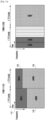
- FIG. 1A illustrates a scheme for providing a URLLC service using resources coexistent with resources used to provide an eMBB service according to an embodiment of the present disclosure.
- a URLLC service may be provided using resources coexistent with resources to provide MBB and LTE services.
- the TTI may indicate the time unit for resource allocation, and the hybrid ARQ round trip time (RTT) and scheduling request time may be defined using an integer multiple of the TTI.
- RTT hybrid ARQ round trip time
- time units of at least two systems may differ.
- the base station may configure two or more actions for the at least two systems.
- the terminal (user equipment, UE) may operate as a single system or operate as two or more systems, and the base station may configure the terminal to operate as a single system or as two or more systems depending on the situations. That is, an eMBB terminal operating as an eMBB system (or using an eMBB service) and a URLLC terminal operating as a URLLC system (or using a URLLC service) may be different terminals. Or, a single terminal may operate as an eMBB terminal or as a URLLC terminal. For ease of description, it is assumed that an eMBB terminal operating as an eMBB system and a URLLC terminal operating as a URLLC system are different terminals.
- TTIs may be multiplexed in the time domain or in the frequency domain.
- Resource regions may be configured semi-statically with respect to a long TTI and a short TTI, and resource allocation may be made within each resource region.
- the resources may be partitioned in the frequency domain into short TTI resources and long TTI resources, and the long TTI resources and the short TTI resources may be multiplexed in a FDM manner.
- the frequency bands 111 and 112 available to the URLLC system may be limited compared to the whole frequency band, and the URLLC system may be not allowed to use the frequency bands 113 and 114 used by the eMBB system. That is, the URLLC service is not provided in the frequency band allocated to the eMBB service. FDM multiplexing may be not efficient for increasing the URLLC system capacity.
- the resources may be partitioned in the time domain into short TTI resources and long TTI resources, and the long TTI resources and the short TTI resources may be multiplexed in a TDM manner.
- the RTT depends on the long TTI
- the effect of latency reduction due to usage of a short TTI may diminish.
- scheduling of the URLLC service is postponed until the short TTI interval is reached, the availability of the URLLC service may decrease.
- FIG. 1B illustrates another scheme for providing a URLLC service using resources coexistent with resources used to provide an eMBB service according to an embodiment of the present disclosure.
- the base station may partition the resources with respect to the eMBB service using the long TTI.
- the base station may interrupt the eMBB service through puncturing and provide a URLLC service to the URLLC terminal.
- the base station may allocate resources to the URLLC terminal first (as indicated by indicia 131, 132, 133, or 134).
- the resource region allocated first to the URLLC terminal may be referred to as a URLLC resource region.
- the size of the frequency domain assigned to the URLLC resource region may be preset or may be determined according to the amount of data for the URLLC service.
- the portion of the URLLC resource region overlapping the resource region allocated to the eMBB system may be referred to as a collision region.
- the base station may puncture data transmission to the eMBB terminal in the collision region and transmit data to the URLLC terminal only. Preferential resource allocation to the URLLC terminal may benefit the URLLC service, but the eMBB system may experience performance degradation when the number of connected URLLC terminals increases.
- the eMBB terminal may mistake URLLC service data as its data and fail to decode eMBB service data.
- the eMBB terminal may suffer severe performance degradation when the amount of punctured resources increases.
- FIGS. 2A and 2B illustrate performance degradation of the eMBB terminal when resources allocated for the eMBB service coexist with resources allocated for the URLLC service.
- FIG. 2A illustrates performance of the eMBB terminal according to whether it is aware of puncturing.
- graph 210 depicts the performance of the eMBB terminal when it is unaware that a portion of the allocated resource region is punctured.
- the eMBB terminal When the eMBB terminal is unaware of puncturing, it may mistake URLLC data as its data and fail to decode eMBB data.
- the block error rate (BLER) hardly decreases with the increasing SNR (signal-to-noise ratio).
- graph 220 depicts the performance of the eMBB terminal when it is aware that a portion of the allocated resource region is punctured. It can be seen that the block error rate decreases with the increasing SNR. That is, the eMBB terminal can decode eMBB data, unlike the case of graph 210.
- FIG. 2B illustrates performance degradation of the eMBB terminal according to the amount of puncturing.
- FIG. 2B depicts the relationship between the SNR and the BLER at the receiving end of the eMBB terminal according to the amount of punctured resources.
- the amount of punctured resources and the positions of the punctured resources are known to the receiving end of the eMBB terminal, this may have an effect corresponding to an increase in the effective coding rate (effect similar to that of rate matching performed at the transmitting end).
- the amount of punctured resources relative to the total resources remains at an equivalent level, and the effective coding rate may be fixed regardless of modulation information.
- graph 230 depicts the relationship between the SNR and the BLER when 9 percent of the total resources are punctured; graph 240 depicts the relationship when 18 percent of the total resources are punctured; graph 250 depicts the relationship when 27 percent of the total resources are punctured; and graph 260 depicts the relationship when 36 percent of the total resources are punctured.
- Comparison between graph 230 and graph 260 may reveal that the SNR value of graph 260 is greater than that of graph 230 for the same BLER value, and the increase in performance degradation of the eMBB terminal becomes larger with the increasing amount of punctured resources.
- the present disclosure proposes a scheme that enables the eMBB terminal to secure available resources by decreasing the amount of puncturing.
- To reduce the amount of puncturing when the same amount of data is transmitted it is necessary to transmit data in an overlapping manner over some resources (referred to as an overlap region).
- the present disclosure proposes a scheme whereby data is transmitted in an overlapping manner in the overlap region of the collision region and the eMBB data is punctured with power adjustment in the remaining region of the collision region.
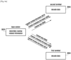
- FIG. 3 illustrates a method for providing different services according to an embodiment of the present disclosure.
- the method provides a first service to a first terminal of a first system employing a first TTI and provides a second service to a second terminal of a second system employing a second TTI.
- the first system is an eMBB system and the second system is a URLLC system
- the first terminal is an eMBB terminal and the second terminal is a URLLC terminal
- the first service is an eMBB service and the second service is a URLLC service.
- the present disclosure is not limited thereto or thereby.
- the base station may receive decoding capability information related to decoding capabilities of a terminal.
- the decoding capability information may include information on a receiver utilizing statistical properties of interference (e.g. non-Gaussian detection) or information on a receiver utilizing the interference signal itself (e.g. interference awareness detection (IAD) or interference cancellation (IC)).
- IAD interference awareness detection
- IC interference cancellation
- Step S310 may be skipped and the base station may perform step S320 without receiving terminal decoding capability information.
- the base station may determine overlap related information.
- the overlap related information may include at least one of collision region information, inter-service power information, puncturing amount information, overlapping signal power information, puncturing information, and modulation information.
- the collision region information may refer to information indicating, among resources allocated to the first terminal, the resource to be allocated to the second terminal in response to a request from the second system.
- the collision region information may indicate the collision region 131, 132, 133 or 134 in FIG. 1B .
- the inter-service power information may refer to information indicating the power ratio between the power assigned to the first service offered to the first system and the power assigned to the second service offered to the second system. Specifically, the inter-service power information may indicate the ratio between the power consumed to provide the first service and the power consumed to provide the second service in a region other than the collision region (referred to as a non-collision region).
- the collision region information and inter-service power information may be determined when the second terminal connects to the base station.
- the puncturing amount information, overlapping signal power information, and puncturing information may be determined based on the decoding capability information received from terminals and requirements of the second system.
- the overlap related information may be determined based on the decoding capability information of the first terminal and second terminal.
- the requirements of the second system may include at least one of a reliability requirement and a latency requirement determined in advance.
- the puncturing amount information may indicate the amount of resources to be punctured in the collision region for the first system data.
- the puncturing amount information is determined, it is possible to determine the overlap amount information indicating the amount of resources in the overlap region of the collision region.
- the puncturing amount information is used as including the overlap amount information.
- the base station may determine the overlap amount information first and then determine the puncturing amount information.
- the overlapping signal power information may indicate the power ratio in the overlap region. That is, while the inter-service power information indicates the ratio between the power consumed to provide the first service and the power consumed to provide the second service in the non-collision region, the overlapping signal power information indicates the ratio between the power consumed to provide the first service and the power consumed to provide the second service in the overlap region of the collision region.
- the inter-service power information is determined when the corresponding terminal is connected, and the base station may adjust the overlapping signal power information to minimize interference between terminals.
- the puncturing information may indicate the ratio between the overlap amount and the puncturing amount in the collision region.
- the puncturing information may have a regular pattern or a randomized pattern. When the puncturing information is used at the receiving end, it may be limited to a regular pattern so as to reduce signaling information. For example, the puncturing information may be identified according to the remainder of the modulo operation on the ratio between the overlap amount and the puncturing amount.
- the puncturing information may be tabulated as a table, which can be stored in the base station or the terminal. When the puncturing information is randomized, it may have a pseudo random pattern including terminal-specific information.
- the base station may adjust the puncturing information, and may obtain diversity gain by adjusting puncturing information between interrupted short TTIs in the same long TTI or by changing puncturing information upon resumption of the second service.
- the base station may identify the overlap region based on the puncturing information and transmit overlapping data in the overlap region to the first terminal and second terminal.
- data for difference services using different TTIs may overlap, and service data is not allowed to overlap control information or reference signals (RS).
- RS reference signals
- a reference signal can be shared between the first system and the second system, but the base station cannot transmit a reference signal on the same resource in an overlapping manner.
- the puncturing amount information, overlapping signal power information, and puncturing information may be determined based on the interference-to-noise power ratio and the cell occupancy of the first system at the time of transmitting the second system service.
- the puncturing amount information and overlapping signal power information may be determined based on the decoding capability information of the second terminal in consideration of the SIR and SNR of the second system.
- the whole collision region may be punctured and data may be sent without overlapping. That is, data may be transmitted without overlapping when the interference level is low or the number of connected second terminals is small.
- optimization level for assuring performance of the second system may be varied according to the latency criticality and reliability requirement of the second system.
- the base station may determine the overlap related information that satisfies the second system requirements and maximizes the first system performance by adjusting the power ratio between the first system and the second system.
- the base station may make the power difference between the two systems large and transmit modulation information of the system with a higher power to the system with a lower power. Thereby, the terminal with lower power assignment may perform interference cancellation.
- the base station may determine the overlap related information maximizing the difference between statistical properties of interference and those of noise. For example, when noise follows a Gaussian distribution, the base station may determine the overlap related information such that interference follows a non-Gaussian distribution. Thereby, the terminal may avoid interference by use of a receiver utilizing statistical properties of interference (e.g. non-Gaussian detection).
- the base station may determine the overlap related information so that the minimum of the Euclidean distance is maximized under a maximum likelihood (ML) criterion.
- ML maximum likelihood
- the base station may transmit the overlap related information and scheduling information to the terminal.
- the overlap related information may include at least one of collision region information, inter-service power information, puncturing amount information, overlapping signal power information, puncturing information, and modulation information.
- the scheduling information to be sent to the terminal may include at least one piece of the above listed information.
- the base station may transmit scheduling information containing overlap related information to the terminal, or may separately transmit scheduling information and overlap related information to the terminal.
- the decoding capability information may include at least one of information on a receiver utilizing statistical properties of interference and information on a receiver utilizing the interference signal itself.
- the information sent to the terminal may be varied according to the information contained in the decoding capability information.
- the base station may transmit the collision region information and power information to the terminal and may not transmit the puncturing information.
- the base station may transmit data to the first terminal and the second terminal based on the overlap related information.
- the base station may transmit first service data in the non-collision region.
- the base station may transmit overlapping data in the overlap region of the collision region based on the puncturing information and overlapping signal information.
- the base station may transmit data to the second terminal only (not to the first terminal) on a resource in the non-overlap region of the collision region.
- the terminal may group received signals into collision region signals and non-collision region signals by use of the collision region information received from the base station.
- the terminal may use a receiver utilizing statistical properties of interference to decode the signal received in the collision region, and use a receiver unconcerned about interference to decode the signal received in the non-collision region.
- the base station may transmit the collision region information, power information, puncturing information, and modulation information to the terminal at step S330.
- the base station may transmit data to the first terminal and the second terminal based on the overlap related information.
- the base station may transmit overlapping data in the overlap region of the collision region based on the puncturing information and overlapping signal information.
- the base station may transmit data to the second terminal only (not to the first terminal) on a resource in the non-overlap region of the collision region.
- the terminal may group received signals into collision region signals and non-collision region signals by use of the puncturing information.
- the terminal may use a receiver applying IAD or IC to decode the signal received in the overlap region, and use a receiver unconcerned about interference to decode the signal received in the non-overlap region. Detailed operations of the terminal are described later.
- the puncturing information may be determined by the ratio between the overlap amount and the puncturing amount in the collision region, and may include regular or randomized information.
- the base station may limit the puncturing information to a regular pattern so as to reduce signaling information.
- the puncturing information may be identified according to the remainder of the modulo operation on the ratio between the overlap amount and the puncturing amount.
- the puncturing information may be tabulated as a table, which can be stored in the base station or the terminal. When the puncturing information is randomized, it may have a pseudo random pattern.
- FIG. 4 illustrates puncturing information according to an embodiment of the present disclosure.
- the first system may operate using a long TTI and the second system may operate using a short TTI.
- the base station may allocate resources to the second terminal.
- the resources allocated to the second terminal may be referred to as a second system resource region as indicated by indicia 410 or 420.
- the base station may allocate a second system resource region 410 or 420 to the second terminal.
- the base station may allocate some resources of the first system resource region 430 or 440 preferentially to the second terminal.
- the portion of the second system resource region overlapping the first system resource region may be referred to as a collision region as indicated by indicia 450.
- the collision region 450 may indicate a resource region where the first system data is punctured to assure performance of the second system.
- the base station may transmit not first system data but second system data, assuring performance of the second system.
- the puncturing information 460 may include information indicating resources in the collision region 450 to be used to transmit overlapping data.
- the puncturing information 460 may also include information indicating resources in the collision region 450 where data puncturing is to be performed.
- the base station may transmit first system data and second system data in an overlapping manner on a resource 461 indicated by the puncturing information.
- the puncturing information 460 includes information indicating resources in the collision region 450 where data puncturing is to be performed
- the base station may puncture first system data on a resource 461 indicated by the puncturing information and may transmit first system data and second system data in an overlapping manner on a resource other than the resource 461 in the collision region 450.
- the base station may transmit first system data in the collision region under the condition of assuring performance of the second system. Thereby, it is possible to reduce the amount of punctured first system data, preventing performance degradation of the first system.
- transmission of overlapping data may cause interference to the terminal, it is necessary to remove such interference.
- FIG. 5 illustrates interference caused by data overlap to the terminal according to an embodiment of the present disclosure.
- transmitting overlapping data in the collision region enables performance enhancement of the first system through reduction of punctured resources.
- the base station may adjust the power ratio between overlapping signals using the overlapping signal power information and may apply interference suppression, interference cancellation or joint detection of desired and interfering signals, thereby increasing system performance.
- the problem of interference caused by data overlapping may be solved by enabling each terminal to utilize an appropriate receiver or by enabling the base station to adjust the power of overlapping signals and puncturing information in consideration of the decoding capability of the second terminal so that the second terminal can remove interference.
- the base station may transmit the overlapping signal power information and puncturing information to the terminal according to the decoding capability information of the terminal. For example, when the decoding capability information includes information on a receiver utilizing the interference signal itself, the base station may adjust the overlapping signal power information and puncturing information for easy detection of an interference signal in consideration of the decoding capability of the terminal and transmit the adjusted overlapping signal power information and puncturing information to the terminal.
- the base station may also transmit the modulation information for the interference signal of the other terminal.
- the terminal may group received signals according to the overlapping signal power information and puncturing information and use different receivers for different signal groups to remove interference.
- the terminal may use a receiver utilizing the interference signal itself to detect an interference signal and detect the desired signal based on the detected interference signal.
- the terminal may also use the modulation information for the interference signal to detect the desired signal based on interference signal detection.
- the base station may adjust the puncturing information and power ratio in consideration of the decoding capability of the terminal so that statistical properties of interference are changed to ease interference removal.
- the base station may form a non-Gaussian interference channel through partial overlapping of data by use of non-Gaussian statistical properties of interference.
- the terminal may use a receiver based on non-Gaussian decoding to remove interference.
- the interfering signal affecting the second terminal may have a non-Gaussian property as indicated by indicia 510.
- the second terminal may use a receiver based on non-Gaussian properties to ensure acceptable performance.
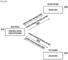
- FIGS. 6A and 6B illustrate signaling between the terminals and base station according to terminal decoding capability information.
- FIG. 6A illustrates signaling between the terminals and base station when terminal decoding capability information contains information on a receiver utilizing statistical properties of interference.
- the first terminal and the second terminal may transmit the base station terminal information containing decoding capability information. Step S610 may be skipped.
- the decoding capability information may include information on a receiver utilizing statistical properties of interference or information on a receiver utilizing an interference signal itself.
- the decoding capability information is assumed to include information on a receiver utilizing statistical properties of interference.
- the base station may determine the overlap related information based on requirements of the second system and the decoding capability information.
- the overlap related information may include at least one of collision region information, inter-service power information, puncturing amount information, overlapping signal power information, puncturing information, and modulation information.
- the base station may determine the puncturing amount information based on the second system requirements and the decoding capability information of the second terminal.
- the other thereof may be determined by use of information on the amount of resources in the collision region.
- the base station may determine the puncturing information and overlapping signal power information associated with a zone of the collision region where data overlapping or data puncturing is to be performed based on the second system requirements and the decoding capability information of the second terminal.
- the base station may increase the power ratio of the overlapping signal power information to ease separation of signals.
- the base station may determine the puncturing information and overlapping signal power information in such a way that statistical properties of interference are different from those of noise (e.g. making interference follow a non-Gaussian distribution).
- the base station may transmit the terminal scheduling information containing the overlap related information.
- the base station may select the overlap related information for the scheduling information in consideration of the decoding capability information of the terminal.
- the base station may select the collision region information and inter-service power information as the overlap related information, which is to be contained in the scheduling information for transmission.
- the overlap related information to be sent to the terminal may further include at least one of the puncturing information, overlapping signal power information, and modulation information.
- the base station may transmit data to the terminal based on the overlap related information.
- the base station may transmit the first terminal and the second terminal overlapping data in the overlap region of the collision region based on the puncturing information contained in the overlap related information.
- the base station may puncture first terminal data in the non-overlap region of the collision region and transmit second terminal data based on the puncturing information.
- the terminal may receive data and decode the received data.
- the first terminal may group resources in the collision region and select receivers for the groups.
- the terminal may decode received data based on the decoding capability information.
- the first terminal may group resources into collision region resources (first group) and non-collision region resources (second group).
- the first terminal may use a receiver utilizing statistical properties of interference for the first group (e.g. non-Gaussian detection (NGD)) and use a receiver unconcerned about interference for the second group (e.g. Gaussian detection (GD)) to decode received data.
- NGD non-Gaussian detection
- GD Gaussian detection
- the second terminal may receive data in the collision region and may receive overlapping data (first terminal data and second terminal data) in the overlap region.
- the second terminal may use a receiver utilizing statistical properties of interference to decode received data.
- the second terminal may group resources in the collision region into overlap region resources and non-overlap region resources, and may use a receiver utilizing statistical properties of interference for the overlap region resources and use a receiver unconcerned about interference for the non-overlap region resources to decode received data.
- FIG. 6B illustrates signaling between the terminals and base station when terminal decoding capability information contains information on a receiver utilizing an interference signal itself.
- the first terminal and the second terminal may transmit the base station terminal information containing decoding capability information. Step S660 may be skipped.
- the decoding capability information may include information on a receiver utilizing statistical properties of interference or information on a receiver utilizing an interference signal itself.
- the decoding capability information is assumed to include information on a receiver utilizing an interference signal itself.
- the base station may determine the overlap related information that maximizes the first system performance (data rate or decoding probability) while satisfying the requirements of the second system based on the decoding capability information of the second system.
- the overlap related information may include at least one of collision region information, power information, overlapping/puncturing amount information, overlapping signal power information, puncturing information, and modulation information.
- the base station may determine the puncturing amount information based on the second system requirements and the decoding capability information of the second terminal.
- the other thereof may be determined by use of information on the amount of resources in the collision region.
- the base station may determine the puncturing information and overlapping signal information associated with a zone of the collision region where data overlapping or data puncturing is to be performed based on the second system requirements and the decoding capability information of the second terminal.
- the base station may determine the puncturing information and overlapping signal information so as to ease detection of an interference signal.
- the base station may examine the modulation information of each overlapping signal.
- the base station may transmit the terminal scheduling information containing the overlap related information.
- the base station may select the overlap related information for the scheduling information in consideration of the decoding capability information of the terminal. For example, when the decoding capability information includes information on a receiver utilizing an interference signal itself, to enable the terminal to detect an interference signal, the base station may configure the overlap related information to include the collision region information, inter-service power information, puncturing information, and modulation information, and transmit scheduling information containing such overlap related information to the terminal.
- the present disclosure is not limited thereto or thereby.
- the scheduling information to be sent to the terminal may further include the overlapping signal power information and modulation information.
- the base station may transmit data to the terminal based on the overlap related information.
- the base station may transmit the first terminal and the second terminal overlapping data in the overlap region of the collision region based on the puncturing information contained in the overlap related information.
- the base station may puncture first terminal data in the non-overlap region of the collision region and transmit second terminal data based on the puncturing information.
- the terminal may receive data and decode the received data.
- the decoding capability information includes information on a receiver utilizing an interference signal itself
- the first terminal and second terminal may use the puncturing information to group signals received in the collision region into overlapping signals and non-overlapping signals. That is, the first terminal and second terminal may distinguish between the overlap region of the collision region and the non-overlap region.
- the non-overlap region may include both a portion of the collision region excluding the overlap region and the non-collision region.
- the first terminal and second terminal may use a receiver utilizing an interference signal itself (e.g. IAD or IC) to decode signals received in the overlap region.
- the first terminal and second terminal may use a receiver unconcerned about interference (e.g. GD) to decode signals received in the non-overlap region. Thereafter, the first terminal and second terminal may separate the desired signal and the interference signal based on decoded signals.
- the decoding capability information of the first terminal and the second terminal is described as containing either information on a receiver utilizing statistical properties of interference or information on a receiver utilizing an interference signal itself.
- the first terminal and the second terminal may have different decoding capability information.
- a description is given of a case where the decoding capability information of the first terminal contains information on a receiver utilizing statistical properties of interference and the decoding capability information of the second terminal contains information on a receiver utilizing an interference signal itself.
- the base station may determine the overlap related information in consideration of the decoding capability information of the first terminal and the second terminal. Specifically, the base station may determine the overlap related information that maximizes the first system performance (data rate or decoding probability) while satisfying the requirements of the second system based on the decoding capability information of the second system.
- the base station may transmit the determined overlap related information to the first terminal and the second terminal.
- the base station may transmit identical overlap related information.
- the base station may transmit different overlap related information according to their decoding capability information of the first terminal and the second terminal.
- the base station may transmit the overlap related information and inter-service power information to the first terminal; and the base station may transmit the puncturing information and overlapping signal power information to the second terminal in addition to the overlap related information and inter-service power information.
- FIG. 7 illustrates a scheme of the base station to transmit scheduling information to a terminal according to an embodiment of the present disclosure.
- the base station may use a dedicated control channel shared in a TDM or FDM fashion or use a control resource region configurable in units of a long TTI at the initial attachment.
- the shared control channel may be multiplexed in a TDM, FDM, or hybrid manner.
- the base station may use several predefined regions to transmit the overlap related information, and the terminal may search the predefined regions for the overlap related information.
- Data and control signals of the second system may be a subband signal, and the time unit thereof for resource allocation may be shorter than that of the first system.
- the first scheme is related to short TTI-based scheduling as indicated by indicia 710.
- the second system services require high reliability and low latency like autonomous driving or e-health. Hence, when second service data is generated, it is necessary to allocate resources to the second service as quickly as possible for providing the second service.
- a separate resource may be used to indicate generation of second system data (or second system traffic 712). It is possible to transmit information indicating generation of second system data on the separate resource, and allocate resources to transmit second system data and control information (referred to as a second system resource region indicated by indicia 713).
- the shared control channel 711 may be used as a resource indicating generation of second system traffic.
- the base station may use the shared control channel 711 partitioned in the frequency domain (in a FDM manner) to indicate generation of second service traffic.
- the base station may transmit information indicating a resource region allocated to the second service together with the information indicating generation of second service data.
- the base station transmits the whole of the overlap related information through the shared control channel 711, the portion of the shared control channel 711 to be continuously monitored by the terminal may increase. This may increase the amount of information to be continuously monitored by the terminal, increasing battery power consumption and decreasing the amount of available resources.
- the base station may notify the location of the second system resource region through the shared control channel, and the terminal may identify the overlap related information through a control channel of the second system resource region.
- the base station may transmit the index of the second system resource region through the shared control channel 711.
- the terminal may continuously monitor the shared control channel 711 to detect generation of second service data.
- the terminal may obtain information on the location of the second system resource region through the shared control channel 711.
- the terminal may decode a control signal sent through the control channel of the second system resource region to identify the overlap related information.
- the first terminal may decode a control signal sent through the control channel of the second system resource region to identify the overlap related information.
- the first terminal and the second terminal may use the overlap related information to group resources to be used for data reception into resource zones, and may determine the receiver to be used based on the resource zones.
- the first terminal and the second terminal may use the receiver for a resource zone to decode received data.
- the second scheme for scheduling the overlap related information is related to long TTI-based scheduling as indicated by indicia 720.
- the base station may transmit the overlap related information as a portion of control information to be sent through a control channel 721 in the next TTI of the TTI (or subframe) where the second system data is generated.
- the control channel 721 may include a control channel of the long TTI.
- the base station may allocate resources for the second service (referred to as a second system resource region indicated by indicia 723) immediately after the control channel 721.
- the base station may reduce the length of the long TTI.
- the terminal may decode control information received through the control channel 721 to identify the overlap related information.
- the second terminal may decode control information received through the control channel 721 to identify the overlap related information.
- the first terminal and the second terminal may use the overlap related information to group resources to be used for data reception into resource zones, and may determine the receiver to be used based on the resource zones.
- the first terminal and the second terminal may use the receiver for a resource zone to decode received data.
- the second scheme does not define a separate shared control channel, and may transmit control information using the control channel region in a specific TTI.
- the third scheme for scheduling the overlap related information is related to reserved short TTI-based scheduling as indicated by indicia 730.
- the base station may perform semi-persistent scheduling when allocating second system resources by reserving resources for the second service in consideration of the frequency of access to the second service.
- the base station may notify generation of second service data by using the control portion of the reserved resource region 733. Additionally, the base station may puncture first service data and perform overlapping based on the pre-agreed overlap related information. When the overlap related information is changed, the base station may transmit the changed overlap related information through the control portion of the reserved resource region 733. The base station may transmit overlap related information such as overlapping signal power information through the control portion.
- the terminal may monitor the reserved resource region 731 or 733 to examine whether information indicating generation of second system traffic is received.
- the terminal may receive data according to the predetermined puncturing information.
- the terminal may receive information indicating generation of second system traffic through the reserved resource region 733 and receive data according to the predetermined puncturing information.
- the first terminal and the second terminal may use the puncturing information to group resources to be used for data reception into resource zones, and may determine the receiver to be used based on the resource zones.
- the first terminal and the second terminal may use the receiver for a resource zone to decode received data.
- the terminal may decode control information received through the reserved resource region 731 or 733 to identify whether the overlap related information is received.
- the terminal may receive data according to the overlap related information.
- the terminal may identify the overlap related information in the reserved resource region 733.
- the first terminal and the second terminal may use the overlap related information to group resources to be used for data reception into resource zones, and may determine the receiver to be used based on the resource zones.
- the first terminal and the second terminal may use the receiver for a resource zone to decode received data.
- the base station may provide scheduling information to the terminal by use of the first to third schemes.
- the terminal may select a receiver according to the type of the received information and decode data in consideration of interference. This is described in detail with reference to FIGS. 8A and 8B .
- FIG. 8A illustrates a scheme for the first terminal to receive data according to scheduling information from the base station.
- the base station may notify the first terminal of at least one of the following information items.
- the terminal may use different receivers to remove interference according to the received information.
- the first terminal has already received or is aware of the collision region information.
- the first terminal may select a receiver based on statistical properties of a resource zone without estimating the puncturing information and modulation information. Specifically, the first terminal may group resources into collision region resources (first group) and non-collision region resources (second group). The first terminal may use a receiver utilizing statistical properties of interference for the first group (e.g. NGD or complex generalized Gaussian distribution (CGGD)) and use a receiver unconcerned about interference for the second group (e.g. GD) to decode received data.
- selection of a receiver based on statistical properties may include grouping resources into resource zones, selecting a receiver for each zone, and decoding data using the selected receivers. A detailed description thereof may be omitted.
- the first terminal may estimate the puncturing information and modulation information and decode data using the receiver utilizing an interference signal itself (e.g. IC or IAD). Specifically, the first terminal may use the puncturing information to group resources into overlap region resources and non-overlap region resources. The first terminal may use the receiver utilizing an interference signal itself for signals received in the overlap region and use a receiver unconcerned about interference for signals received in the non-overlap region to receive and decode data.
- decoding data based on a receiver utilizing an interference signal itself may include grouping resources into resource zones, selecting a receiver for each resource zone, and decoding data using the selected receivers. A detailed description thereof may be omitted.
- the first terminal may select a receiver based on statistical properties for each resource zone and decode data using the selected receiver without estimating the modulation information.
- the first terminal when the first terminal includes a receiver utilizing an interference signal itself, the first terminal may estimate the modulation information and decode data using the receiver utilizing an interference signal itself (e.g. IC or IAD).
- an interference signal e.g. IC or IAD
- the first terminal When the first terminal includes a receiver utilizing an interference signal itself and the base station transmits information items A, B and C to the first terminal, the first terminal may decode data by use of the receiver utilizing an interference signal itself (e.g. IC or IAD).
- an interference signal e.g. IC or IAD
- the first terminal When the first terminal includes a receiver utilizing an interference signal itself and the base station transmits information items A, B, C and D to the first terminal, the first terminal may decode data by use of the receiver utilizing an interference signal itself (e.g. IC or IAD).
- an interference signal e.g. IC or IAD
- the base station transmits information items A, B, C and D to the first terminal
- the first terminal may decode data by use of a receiver utilizing statistical properties of interference.
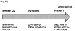
- FIG. 8B illustrates a scheme for the second terminal to receive data according to scheduling information from the base station.
- the base station may notify the second terminal of at least one of the following information items.
- the second terminal may select a receiver based on statistical properties of the collision region and decode data received using the selected receiver.
- the second terminal may group resources in the collision region, select a receiver for each resource group, and decode received data. That is, the second terminal may group collision region resources into overlap region resources and non-overlap zone resources, use a receiver utilizing statistical properties of interference for data received in the overlap region, and use a receiver unconcerned about interference for data received in the non-overlap region.
- the second terminal When the second terminal includes a receiver utilizing an interference signal itself and the base station transmits information items A, B and C to the second terminal, the second terminal may decode data by use of the receiver utilizing an interference signal itself (e.g. IC or IAD).
- an interference signal e.g. IC or IAD
- the information item to be contained in the overlap related information may be changed according to whether the base station transmits the scheduling information via the shared control channel or together with second system control information.
- an indication to whether second service data is present at a particular symbol may be made via the shared control channel.
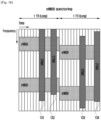
- FIG. 9 illustrates a frame structure including a first system resource region and a second system resource region.
- the control channel of the second system resource region may be localized or distributed in a short TTI.
- the shared control channel 911 may be located at one of frame partitions in the time domain. Control information for the first terminal and second terminal may be sent through the shared control channel 911. Such control information may include information regarding the first system resource region 912 or 913 and the second system resource region 914 or 915.
- the first system resource region 912 and the first system resource region 913 may indicate resource regions allocated to different first terminals.
- the second system resource region 914 and the second system resource region 915 may indicate resource regions allocated to different second terminals.
- the control information for the second system may be sent through the control channel 917 of the second system resource region 914 or 915.
- the overlap related information may be sent through the control channel 917.
- the overlap related information may be sent through the shared control channel 911.
- the shared control channel 921 may be located at one of frame partitions in the frequency domain. Control information for the first terminal and second terminal may be sent through the shared control channel 921. Such control information may include information regarding the first system resource region 922 or 923 and the second system resource region 924 or 925.
- the control information for the first system may be sent through the first system control channel 926 of the first system resource region.
- the control information for the second system may be sent through the second system control channel 929 of the second system resource region.
- the overlap related information may be sent through the first system control channel 926 or the second system control channel 929.
- the overlap related information may be sent through the second system control channel, and the first terminal and the second terminal may identify the overlap related information by decoding control information.
- the overlap related information may be sent through the shared control channel 921.
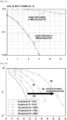
- FIG. 10 illustrates system performance when the proposed method is applied.
- diagram 1010 depicts the performance of the first system when the first system coexists with the second system.
- graph 1012 indicates a case where first system data is fully punctured when second system data is generated; and graph 1011 indicates a case where a portion of first system data (3/4 puncturing) overlaps with second system data when second system data is generated.
- a comparison between graph 1011 and graph 1012 may reveal that the SNR value of graph 1012 is greater than that of graph 1011 at the same BLER value. In other words, it can be seen that first system performance is better when data partially overlaps than when all data is punctured.
- diagram 1020 depicts the performance of the second system when the first system coexists with the second system. Specifically, diagram 1020 depicts the performance of the second system according to the cell loading of the first system.
- graph 1021 indicates a case where there is no interference (no data overlap); graph 1022 indicates a case where the cell loading is 30 percent; and graph 1023 indicates a case where the cell loading is 50 percent.
- a comparison between graphs 1021, 1022 and 1023 may reveal that second system performance does not degrade with the increasing cell loading.
- first system performance without significant degradation of second system performance. That is, it is possible to secure available resources of the first system or the second system while utilizing the same resources of the second system. For example, referring to FIG. 10 , it is possible to increase the available resources of the first system by 130 percent while allocating the same second system resources.
- FIG. 11A is a block diagram of a base station according to an embodiment of the present disclosure.
- the base station may include a transceiver (or communication unit) 1110, a controller (control unit) 1120, and a memory (storage unit) 1130.
- a transceiver or communication unit
- controller control unit
- memory storage unit
- the controller may be a circuit, an application-specific integrated circuit or at least one processor.
- the transceiver1110 may communicate with a different network entity.
- the transceiver1110 may receive terminal information containing decoding capability information from a terminal, and may transmit scheduling information containing overlap related information to the terminal.
- the controller 1120 may control the transceiver1110 to receive terminal information containing decoding capability information from a terminal.
- the controller 1120 may control identifying or determining overlap related information for a first terminal of a first system employing a first TTI and a second terminal of a second system employing a second TTI different from the first TTI.
- the overlap related information may include at least one of collision region information, inter-service power information, puncturing amount information, overlapping signal power information, puncturing information, and modulation information.
- the controller 1120 may control allocating a portion of a resource region allocated to the first system to the second system.
- the controller 1120 may control determining overlap related information in those resources allocated to both the first system and the second system (referred to as a collision region).
- the controller 1120 may determine the overlap related information in consideration of decoding capability information received from the terminal and requirements of the second system. For example, when the decoding capability information includes information on a receiver that performs decoding by treating interference as noise or the base station has not received terminal information, the controller 1120 may increase the power ratio of the overlapping signal power information to ease separation of signals. The controller 1120 may determine the puncturing information and overlapping signal power information in such a way that statistical properties of interference are different from those of noise (e.g. making interference follow a non-Gaussian distribution). In addition, the controller 1120 may detect desired information and interference information jointly by use of modulation information as to interference itself.
- the controller 1120 may control transmitting scheduling information containing the overlap related information to the terminal.
- the controller 1120 may control changing the information to be included in the scheduling information according to the decoding capability information of the terminal.
- the controller 1120 may control transmitting scheduling information containing collision region information and inter-service power information only.
- the controller 1120 may control transmitting scheduling information which contains collision region information, inter-service power information, puncturing information, and modulation information.
- the information included in the scheduling information may be changed.
- the controller 1120 may use at least one of the three schemes (short TTI based scheduling, long TTI based scheduling, and reserved short TTI based scheduling). A detailed description on these schemes is given above in connection with FIG. 7 , and a repeated description thereon is omitted.
- controller 1120 may transmit data to the first terminal and second terminal based on the overlap related information.
- the controller 1120 may transmit first system data and second system data in an overlapping manner on a resource in the overlap region of the collision region.
- the controller 1120 may puncture first system data and transmit second system data only on a resource in the non-overlap region of the collision region.
- the controller 1120 may control all operations of the base station performed in accordance with embodiments of the present disclosure.
- the memory 1130 may store decoding capability information received from the terminal.
- the memory 1130 may store information regarding requirements of each system (e.g. second system requirements).
- the memory 1130 may store information regarding a reserved resource region, and store the puncturing information and overlap related information set in advance.
- FIG. 11B illustrates a configuration of the scheduler according to an embodiment of the present disclosure.
- the scheduler may be included in the controller of the base station or be included in the base station as a separate entity.
- the scheduler may include a first MAC 1121, controller 1120, second MAC 1122, first coding/mod 1123, second coding/mod 1124, and multi-TTI MUX 1125.
- the first MAC 1121 may transmit the data to the controller 1120.
- the second MAC 1122 may transmit the data to the controller 1120.
- the controller 1120 may function in the same way as the controller of the base station. That is, the controller 1120 may determine the overlap related information by use of the decoding capability information received from the terminal. For example, in an environment where noise predominates over interference or cell loading is low for every service, the controller 1120 may set the overlap amount of the overlap related information to zero. The controller 1120 may determine the lower limit and upper limit of the overlap related information based on the latency requirement and reliability requirement of the second system. When the latency requirement of the second system is relatively strict and allows some slack time, the controller 1120 may change the modulation information (e.g. MCS) at the time for scheduling the existing service and schedule the terminal. In this case, the controller 1120 may puncture a portion of existing service resources and transmit existing service data and second service data in an overlapping manner according to the overlap related information (including puncturing amount information and puncturing information) determined when the latency requirement of the second service is relatively loose.
- MCS modulation information
- controller 1120 may transmit data based on the overlap related information.
- the first coding/mod 1123 and the second coding/mod 1124 may encode first service data and second service data, respectively.
- the multi-TTI MUX 1125 may multiplex first service data and second service data. Here, the first service and the second service have different TTIs.
- the multi-TTI MUX 1125 may multiplex data in an overlapping manner on some resources and map the multiplexed data to physical resources under the control of the controller 1120.
- FIG. 12 illustrates a terminal according to an embodiment of the present disclosure.
- the terminal may include a transceiver (or communication unit) 1210, a controller (or control unit) 1220, and a memory (storage unit) 1230.
- the controller may be a circuit, an application-specific integrated circuit or at least one processor.”
- the transceiver1210 may communicate with a different network entity.
- the transceiver1210 may transmit terminal information containing decoding capability information of the terminal to the base station, and may receive scheduling information and data from the base station.
- the controller 1220 may control transmitting terminal information containing decoding capability information to the base station.
- the controller 1220 may receive scheduling information from the base station and decode the scheduling information to identify overlap related information.
- the controller 1220 may decode control information received through the control channel of the long TTI (or subframe) to identify overlap related information contained in the control information. Or, the controller 1220 may monitor a separate shared control channel to identify whether second system traffic is generated, and may receive control information through a control channel of the allocated resource region to identify the overlap related information. Or, the controller 1220 may monitor a control channel of a reserved resource region to identify whether second system traffic is generated and overlap related information.
- the controller 1220 may group resources of the resource region based on the decoding capability information and overlap related information, and select receivers for individual resource groups to decode data.
- the controller 1220 may group resources in the resource region into collision region resources and non-collision region resources by use of the collision region information contained in the overlap related information.
- the controller 1220 may use the receiver utilizing statistical properties of interference for the collision region and use a receiver unconcerned about interference for the non-collision region to receive and decode data.
- the controller 1220 may use the receiver utilizing statistical properties of interference for the whole resource region, without grouping resources, to receive and decode data.
- the controller 1220 may use the receiver to remove interference. To this end, the controller 1220 may identify the overlap region by use of the puncturing information contained in the overlap related information, and group resources of the allocated resource region into overlap region resources and non-overlap region resources. The controller 1220 may use the receiver utilizing an interference signal itself for the overlap region and use a receiver unconcerned about interference for the non-overlap region to receive and decode data.
- the controller 1220 may detect an interference signal and detect a desired signal by using the interference signal.
- the memory 1230 may store decoding capability information of the terminal.
- the memory 1230 may store the scheduling information received from the base station and identified overlap related information.
- the memory 1230 may store information regarding a reserved resource region, and store the puncturing information and overlap related information set in advance.
Landscapes
- Engineering & Computer Science (AREA)
- Signal Processing (AREA)
- Computer Networks & Wireless Communication (AREA)
- Quality & Reliability (AREA)
- Environmental & Geological Engineering (AREA)
- Physics & Mathematics (AREA)
- General Physics & Mathematics (AREA)
- Radar, Positioning & Navigation (AREA)
- Remote Sensing (AREA)
- Mobile Radio Communication Systems (AREA)
Claims (14)
- Procédé effectué par une station de base dans un système de communication, le procédé comprenant :déterminer (S320) une première information indiquant des premières ressources où des premières données pour un premier terminal et des deuxièmes données pour un deuxième terminal doivent être transmises et une deuxième information sur un rapport de puissance entre une puissance pour les premières données et une puissance pour les deuxièmes données dans les premières ressources, où les premières ressources sont parmi des deuxièmes ressources où des ressources attribuées au premier terminal et des ressources attribuées au deuxième terminal se chevauchent ;transmettre (S330), au premier terminal et au deuxième terminal, des informations de commande incluant la première information et la deuxième information ; ettransmettre (S340), au premier terminal et au deuxième terminal, les premières données et les deuxièmes données sur la base des informations de commande,où les informations de commande indiquent que le premier terminal décode les premières données sur la base du rapport de puissance identifiant des interférences des deuxièmes données.
- Procédé selon la revendication 1,où des données pour le premier terminal sont perforées dans les deuxièmes ressources excluant les premières ressources,où le premier terminal est associé à un service de large bande mobile évolué, eMBB, etoù le deuxième terminal est associé à un service de communications de faible latence et ultra-fiable, URLLC.
- Procédé selon la revendication 1,où les informations de commande comprennent en outre au moins l'une entre une troisième information indiquant la deuxième ressource ou une information de modulation pour chacune des premières données et des deuxièmes données,où les informations de commande sont déterminées sur la base des informations de capacité de décodage pour chacun du premier terminal et du deuxième terminal,où les informations de capacité de décodage incluent des informations sur un récepteur utilisant des propriétés statistiques d'interférence ou des informations sur un récepteur utilisant un signal d'interférence, etoù les informations de commande sont utilisées par le premier terminal pour identifier les premières ressources et pour décoder les premières données transmises sur les premières ressources en considérant l'interférence des deuxièmes données.
- Procédé effectué par un premier terminal dans un système de communication, le procédé comprenant :recevoir, d'une station de base, des informations de commande incluant une première information indiquant des premières ressources où des premières données pour le premier terminal et des deuxièmes données pour un deuxième terminal doivent être transmises et une deuxième information sur un rapport de puissance entre une puissance pour les premières données et une puissance pour les deuxièmes données dans les premières ressources, où les premières ressources sont parmi des deuxièmes ressources où des ressources attribuées au premier terminal et des ressources attribuées au deuxième terminal se chevauchent,identifier les premières ressources sur la base des informations de commande ;recevoir, de la station de base, les premières données et les deuxièmes données sur les premières ressources et ;décoder les premières données sur la base du rapport de puissance identifiant des interférences des deuxièmes données.
- Procédé selon la revendication 4,où des données pour le premier terminal dans les deuxièmes ressources excluant les premières ressources sont perforées,où le premier terminal est associé à un service de large bande mobile évolué, eMBB,où le deuxième terminal est associé à un service de communications de faible latence et ultra-fiable, URLLC,où les informations de commande comprennent en outre au moins l'une entre une troisième information indiquant les deuxièmes ressources et une information pour chacune des premières données et les deuxièmes données,où les informations de commande sont déterminées sur la base des informations de capacité de décodage pour chacun du premier terminal et du deuxième terminal, etoù les informations de capacité de décodage incluent des informations sur un récepteur utilisant des propriétés statistiques d'interférence ou des informations sur un récepteur utilisant un signal d'interférence.
- Procédé selon la revendication 4, où l'identification des premières ressources comprend :
grouper les ressources attribuées au premier terminal dans un premier groupe incluant les premières ressources et un deuxième groupe incluant des troisièmes ressources excluant les premières ressources des ressources attribuées au premier terminal sur la base des informations de commande. - Procédé selon la revendication 6, où le décodage des premières données comprend :identifier un récepteur associé au premier groupe ; etdécoder les premières données utilisant le récepteur en considérant les interférences des deuxièmes données.
- Station de base dans un système de communication, la station de base comprenant :un émetteur-récepteur (1110) ; etun contrôleur (1120) configuré pour :déterminer une première information indiquant des premières ressources où des premières données pour un premier terminal et des deuxièmes données pour un deuxième terminal doivent être transmises et une deuxième information sur un rapport de puissance entre une puissance pour les premières données et une puissance pour les deuxièmes données dans les premières ressources, où les premières ressources sont parmi des deuxièmes ressources où des ressources attribuées au premier terminal et des ressources attribuées au deuxième terminal se chevauchent,transmettre, au premier terminal et au deuxième terminal via l'émetteur-récepteur, des informations de commande incluant la première information et la deuxième information, ettransmettre, au premier terminal et au deuxième terminal via l'émetteur-récepteur, les premières données et les deuxièmes données sur la base des informations de commande,où les informations de commande indiquent que le premier terminal décode les premières données sur la base du rapport de puissance identifiant les interférences des deuxièmes données.
- Station de base selon la revendication 8,où des données pour le premier terminal sont perforées dans les deuxièmes ressources excluant les premières ressources,où le premier terminal est associé à un service de large bande mobile évolué, eMBB, etoù le deuxième terminal est associé à un service de communications de faible latence et ultra-fiable, URLLC.
- Station de base selon la revendication 8,où les informations de commande comprennent en outre au moins l'une entre une troisième information indiquant les deuxièmes ressources ou une information pour chacune des premières données et des deuxièmes données,où les informations de commande sont déterminés sur la base d'informations de capacité de décodage pour chacun du premier terminal et du deuxième terminal,où les informations de capacité de décodage incluent des informations sur un récepteur utilisant des propriétés statistiques d'interférence ou des informations sur un récepteur utilisant un signal d'interférence, etoù les informations de commande sont utilisées par le premier terminal pour identifier les premières ressources et pour décoder les premières données transmises sur la première ressources en considérant les interférences des deuxièmes données.
- Premier terminal dans un système de communication, le premier terminal comprenant :un émetteur-récepteur (1210) ; etun contrôleur (1220) configuré pour :recevoir, d'une station de base via l'émetteur-récepteur, des informations de commande incluant une première information indiquant des premières ressources où des premières données pour le premier terminal et des deuxièmes données pour un deuxième terminal doivent être transmises et une deuxième information sur un rapport de puissance entre une puissance pour les premières données et une puissance pour les deuxièmes données dans les premières ressources, où les premières ressources sont parmi des deuxièmes ressources où des ressources attribuées au premier terminal et des ressources attribuées au deuxième terminal se chevauchent,identifier les premières ressources sur la base des informations de commande,recevoir, de la station de base via l'émetteur-récepteur, les premières données et les deuxièmes données sur les premières ressources, etdécoder les premières données sur la base du rapport de puissance identifiant les interférences des deuxièmes données.
- Premier terminal selon la revendication 11,où des données pour le premier terminal dans les deuxièmes ressources excluant les première ressources sont perforées,où le premier terminal est associé à un service de large bande mobile évolué, eMBB,où le deuxième terminal est associé à un service de communications de faible latence et ultra-fiable, URLLC,où les informations de commande comprennent en outre au moins l'une entre une troisième information indiquant les deuxièmes ressources et une information de modulation pour chacune des premières données et des deuxièmes données,où les informations de commande sont déterminées sur la base des informations de capacité de décodage pour chacun du premier terminal et le deuxième terminal, etoù les informations de capacité de décodage incluent des informations sur un récepteur utilisant des propriétés statistiques d'interférence ou des informations sur un récepteur utilisant un signal d'interférence.
- Premier terminal selon la revendication 11, où le contrôleur (1220) est configuré pour :
grouper les ressources attribuées au premier terminal dans un premier groupe incluant les premières ressources et un deuxième groupe incluant des troisièmes ressources excluant les premières ressources des ressources attribuées au premier terminal sur la base des informations de commande. - Premier terminal selon la revendication 11, où le contrôleur (1220) est configuré pour :identifier un récepteur associé au premier groupe, etdécoder les premières données utilisant le récepteur en considérant l'interférence des deuxièmes données.
Applications Claiming Priority (2)
| Application Number | Priority Date | Filing Date | Title |
|---|---|---|---|
| KR1020160039730A KR102458074B1 (ko) | 2016-03-31 | 2016-03-31 | 이동 통신 시스템에서 이종 서비스 제공 방법 및 장치 |
| PCT/KR2017/003599 WO2017171504A1 (fr) | 2016-03-31 | 2017-03-31 | Procédé et appareil pour fournir différents services dans un système de communication mobile |
Publications (3)
| Publication Number | Publication Date |
|---|---|
| EP3420664A1 EP3420664A1 (fr) | 2019-01-02 |
| EP3420664A4 EP3420664A4 (fr) | 2019-02-27 |
| EP3420664B1 true EP3420664B1 (fr) | 2023-08-09 |
Family
ID=59961456
Family Applications (1)
| Application Number | Title | Priority Date | Filing Date |
|---|---|---|---|
| EP17775928.9A Active EP3420664B1 (fr) | 2016-03-31 | 2017-03-31 | Procédé et appareil pour fournir différents services dans un système de communication mobile |
Country Status (5)
| Country | Link |
|---|---|
| US (1) | US20170285130A1 (fr) |
| EP (1) | EP3420664B1 (fr) |
| KR (1) | KR102458074B1 (fr) |
| CN (1) | CN108781158B (fr) |
| WO (1) | WO2017171504A1 (fr) |
Families Citing this family (23)
| Publication number | Priority date | Publication date | Assignee | Title |
|---|---|---|---|---|
| JP6800982B2 (ja) | 2015-12-30 | 2020-12-16 | アイディーエーシー ホールディングス インコーポレイテッド | マルチrat wtruにおける干渉の処理 |
| EP3764581A1 (fr) * | 2016-03-30 | 2021-01-13 | IDAC Holdings, Inc. | Accès radio flexible nr assisté par évolution à long terme (lte) |
| SG10202001291QA (en) * | 2016-04-08 | 2020-04-29 | Idac Holdings Inc | Phy layer multiplexing of different types of traffic in 5g systems |
| US10314065B2 (en) * | 2016-04-12 | 2019-06-04 | Qualcomm Incorporated | Traffic multiplexing |
| US10912082B2 (en) * | 2016-04-19 | 2021-02-02 | Lg Electronics Inc. | Ways for supporting multiple TTIs |
| US20170332401A1 (en) | 2016-05-13 | 2017-11-16 | Qualcomm Incorporated | Multiple transmission time interval coexistence |
| US10848266B2 (en) * | 2016-07-01 | 2020-11-24 | Lg Electronics Inc. | Data reception method and device, and data transmission method and device |
| US10419264B2 (en) * | 2016-07-27 | 2019-09-17 | Qualcomm Incorporated | Subframe structure for the co-existence network of sidelink and mission critical mobile devices |
| CN109561433B (zh) | 2016-08-10 | 2020-03-20 | 华为技术有限公司 | 数据信道发送和接收方法、网络设备及终端 |
| EP3535886B1 (fr) | 2016-11-02 | 2024-10-09 | InterDigital Patent Holdings, Inc. | Conception d'un canal de données partagé |
| US10097260B2 (en) * | 2017-02-06 | 2018-10-09 | Qualcomm Incorporated | Current indication channel for eMBB/URLLC multiplexing |
| US10244522B2 (en) * | 2017-03-03 | 2019-03-26 | Qualcomm Incorporated | Signaling for multiplexing of low latency communication and sidelink communications |
| CN115765921A (zh) * | 2017-03-23 | 2023-03-07 | 瑞典爱立信有限公司 | 第二服务传输中的第一服务数据的打孔成束的方法和装置 |
| EP3602879B1 (fr) | 2017-03-23 | 2022-12-07 | Telefonaktiebolaget LM Ericsson (publ) | Configuration de paquets de données de ponction pour un premier service dans une transmission d'un second service |
| WO2018195864A1 (fr) * | 2017-04-27 | 2018-11-01 | 北京小米移动软件有限公司 | Procédé et appareil de multiplexage et de transmission de service, et support de stockage lisible par ordinateur |
| CN110167156B (zh) * | 2018-02-13 | 2023-07-25 | 北京紫光展锐通信技术有限公司 | 上行复用时频资源确定方法、用户终端及可读存储介质 |
| CN112005606B (zh) * | 2018-03-20 | 2024-06-21 | 诺基亚技术有限公司 | 确定要打孔的mbb ue以适应urllc业务 |
| CN112352406B (zh) * | 2018-06-28 | 2024-03-01 | 株式会社Ntt都科摩 | 用户终端以及无线通信方法 |
| CN109714735B (zh) | 2018-12-25 | 2020-07-24 | 深圳职业技术学院 | 一种物联网中鲁棒的数据传输方法 |
| CN109618362A (zh) * | 2019-02-15 | 2019-04-12 | 中国联合网络通信集团有限公司 | 一种通信方法及设备 |
| US10797749B1 (en) | 2019-03-11 | 2020-10-06 | Google Llc | Base station coordination for cross-link interference cancelation |
| CN109922488B (zh) * | 2019-04-26 | 2021-04-23 | 电子科技大学 | 实时无线控制系统中urllc分组丢弃的设计方法 |
| US11589348B2 (en) * | 2019-08-27 | 2023-02-21 | Qualcomm Incorporated | Reception of overlapping physical downlink shared channel communications |
Family Cites Families (28)
| Publication number | Priority date | Publication date | Assignee | Title |
|---|---|---|---|---|
| US8085831B2 (en) * | 2004-05-17 | 2011-12-27 | Qualcomm Incorporated | Interference control via selective blanking/attenuation of interfering transmissions |
| US8879511B2 (en) * | 2005-10-27 | 2014-11-04 | Qualcomm Incorporated | Assignment acknowledgement for a wireless communication system |
| US9419749B2 (en) * | 2009-08-19 | 2016-08-16 | Qualcomm Incorporated | Methods and apparatus employing FEC codes with permanent inactivation of symbols for encoding and decoding processes |
| US7693908B2 (en) * | 2007-06-28 | 2010-04-06 | Microsoft Corporation | Determination of time dependency of search queries |
| WO2009131162A1 (fr) * | 2008-04-25 | 2009-10-29 | シャープ株式会社 | Système de communication multiporteuse, dispositif de communication et procédé de communication |
| WO2010080632A2 (fr) * | 2008-12-18 | 2010-07-15 | Nec Laboratories America, Inc. | Systèmes d'accès multiple par répartition en fréquence orthogonale multi-utilisateurs à entrée multiple sortie multiple (mu-mimo-ofdma) et procédé pour offrir un service à des utilisateurs co-programmés en chevauchement |
| EP2372927A4 (fr) * | 2008-12-24 | 2016-06-01 | Lg Electronics Inc | Procédé d'affectation de ressources pour un relais |
| US9444589B2 (en) * | 2009-10-05 | 2016-09-13 | Qualcomm Incorporated | Method and apparatus for puncturing data regions for signals to minimize data loss |
| US20110151910A1 (en) * | 2009-12-18 | 2011-06-23 | Electronics And Telecommunications Research Institute | Method and apparatus for allocating resources for physical channel in mobile communication system |
| US8965294B2 (en) * | 2010-03-24 | 2015-02-24 | Lg Electronics Inc. | Method and apparatus for reducing inter-cell interference in radio communication system |
| CN103155456B (zh) * | 2010-08-11 | 2016-06-29 | 株式会社泛泰 | 发送静默信息的装置和方法与获取信道状态的装置和方法 |
| ES2751931T3 (es) * | 2010-08-13 | 2020-04-02 | Lg Electronics Inc | Método y estación base para transmitir señal de enlace descendente y método y equipo para recibir señal de enlace descendente |
| US9258092B2 (en) * | 2010-09-17 | 2016-02-09 | Blackberry Limited | Sounding reference signal transmission in carrier aggregation |
| WO2012091443A2 (fr) * | 2010-12-28 | 2012-07-05 | 엘지전자 주식회사 | Procédé et dispositif d'émission / réception d'un signal dans un système de communication hertzienne en tdd |
| JP2012147048A (ja) * | 2011-01-06 | 2012-08-02 | Ntt Docomo Inc | 無線基地局装置、移動端末装置、及び無線通信方法 |
| US10250364B2 (en) * | 2011-12-09 | 2019-04-02 | Nokia Corporation | Channel measurements supporting coordinated multi-point operation |
| KR101407094B1 (ko) * | 2012-10-31 | 2014-06-16 | 엘지전자 주식회사 | 상향링크 신호 전송 방법 및 장치 |
| EP2946498A1 (fr) * | 2013-01-17 | 2015-11-25 | Telefonaktiebolaget LM Ericsson (PUBL) | Procédés de transmission et/ou de réception de transmissions de données en utilisant des informations relatives à d'autres transmissions de données et n uds de réseau associés |
| US9780934B2 (en) * | 2013-05-09 | 2017-10-03 | Lg Electronics Inc. | Method for puncturing UE specific reference signal in radio access system supporting new carrier type and apparatus supporting same |
| WO2014208940A1 (fr) * | 2013-06-26 | 2014-12-31 | 엘지전자 주식회사 | Procédé de fonctionnement pour dispositif mtc |
| CN104796920B (zh) * | 2014-01-16 | 2019-02-12 | 电信科学技术研究院 | 数据传输方法、基站以及终端设备 |
| US11452121B2 (en) * | 2014-05-19 | 2022-09-20 | Qualcomm Incorporated | Apparatus and method for synchronous multiplexing and multiple access for different latency targets utilizing thin control |
| US10939454B2 (en) * | 2014-12-11 | 2021-03-02 | Qualcomm Incorporated | Prioritizing colliding transmissions in LTE and ultra-low latency LTE communications |
| KR102457295B1 (ko) * | 2015-01-07 | 2022-10-21 | 삼성전자 주식회사 | 이동 통신 시스템에서 전력 소모 제어 방법 및 장치 |
| US9999074B2 (en) * | 2015-01-30 | 2018-06-12 | Electronics And Telecommunications Research Institute | Method and apparatus for transmitting downlink reference signal and method and apparatus for transmitting control information in cooperative multi-point communication system |
| US10448405B2 (en) * | 2015-03-19 | 2019-10-15 | Qualcomm Incorporated | Methods and apparatus for mitigating resource conflicts between ultra low latency (ULL) and legacy transmissions |
| US9775045B2 (en) * | 2015-09-11 | 2017-09-26 | Intel IP Corporation | Slicing architecture for wireless communication |
| WO2017166108A1 (fr) * | 2016-03-30 | 2017-10-05 | Nec Corporation | Procédés et appareils pour émettre et recevoir des signaux de référence |
-
2016
- 2016-03-31 KR KR1020160039730A patent/KR102458074B1/ko active Active
-
2017
- 2017-03-31 WO PCT/KR2017/003599 patent/WO2017171504A1/fr not_active Ceased
- 2017-03-31 CN CN201780018280.0A patent/CN108781158B/zh active Active
- 2017-03-31 EP EP17775928.9A patent/EP3420664B1/fr active Active
- 2017-03-31 US US15/476,845 patent/US20170285130A1/en not_active Abandoned
Also Published As
| Publication number | Publication date |
|---|---|
| EP3420664A1 (fr) | 2019-01-02 |
| CN108781158B (zh) | 2021-10-22 |
| CN108781158A (zh) | 2018-11-09 |
| WO2017171504A1 (fr) | 2017-10-05 |
| EP3420664A4 (fr) | 2019-02-27 |
| KR20170112561A (ko) | 2017-10-12 |
| KR102458074B1 (ko) | 2022-10-24 |
| US20170285130A1 (en) | 2017-10-05 |
Similar Documents
| Publication | Publication Date | Title |
|---|---|---|
| US20170285130A1 (en) | Method and apparatus for providing different services in mobile communication system | |
| US11811430B2 (en) | Transmission device, receiving device, transmission method, and receiving method | |
| US10798692B2 (en) | Method and device for providing control information for different services | |
| US11115982B2 (en) | Telecommunications apparatuses and methods | |
| JP7091358B2 (ja) | トラフィックを多重化するためのシステムおよび方法 | |
| CN110603774B (zh) | 用于第5代(5g)新无线电接入技术(nr)的短pucch格式和调度请求(sr)传输 | |
| US8811321B2 (en) | Method for transceiving a downlink reference signal, and base station and user equipment using same | |
| JP7634743B2 (ja) | 端末、受信方法及び集積回路 | |
| US20120195216A1 (en) | Systems and methods for adaptive channel access | |
| CN108282864B (zh) | 通信方法、网络侧设备和终端设备 | |
| US10568078B2 (en) | User equipment and base station | |
| WO2021029124A1 (fr) | Dispositif de transmission, dispositif de réception, procédé de transmission, et procédé de réception | |
| TWI731547B (zh) | 用於未授權頻譜中無線通訊的方法 | |
| JP2019507969A (ja) | 通信方法、端末デバイス及びネットワークデバイス | |
| CN117998592A (zh) | 一种tbs确定方法、装置及存储介质 | |
| US20150139164A1 (en) | Base station apparatus, mobile station apparatus, communication system, and communication method | |
| EP4373000A2 (fr) | Terminal et station de base prenant en charge de multiples états d'indicateur de configuration de transmission et procédés de fonctionnement associés |
Legal Events
| Date | Code | Title | Description |
|---|---|---|---|
| STAA | Information on the status of an ep patent application or granted ep patent |
Free format text: STATUS: THE INTERNATIONAL PUBLICATION HAS BEEN MADE |
|
| PUAI | Public reference made under article 153(3) epc to a published international application that has entered the european phase |
Free format text: ORIGINAL CODE: 0009012 |
|
| STAA | Information on the status of an ep patent application or granted ep patent |
Free format text: STATUS: REQUEST FOR EXAMINATION WAS MADE |
|
| 17P | Request for examination filed |
Effective date: 20180924 |
|
| AK | Designated contracting states |
Kind code of ref document: A1 Designated state(s): AL AT BE BG CH CY CZ DE DK EE ES FI FR GB GR HR HU IE IS IT LI LT LU LV MC MK MT NL NO PL PT RO RS SE SI SK SM TR |
|
| AX | Request for extension of the european patent |
Extension state: BA ME |
|
| A4 | Supplementary search report drawn up and despatched |
Effective date: 20190125 |
|
| RIC1 | Information provided on ipc code assigned before grant |
Ipc: G01S 5/02 20100101ALI20190121BHEP Ipc: H04L 12/26 20060101ALI20190121BHEP Ipc: H04W 72/12 20090101ALI20190121BHEP Ipc: H04W 72/04 20090101ALI20190121BHEP Ipc: H04L 12/24 20060101ALI20190121BHEP Ipc: H04L 29/08 20060101ALI20190121BHEP Ipc: H04L 5/00 20060101AFI20190121BHEP Ipc: H04W 4/70 20180101ALI20190121BHEP Ipc: H04L 1/18 20060101ALI20190121BHEP Ipc: H04L 1/00 20060101ALI20190121BHEP |
|
| DAV | Request for validation of the european patent (deleted) | ||
| DAX | Request for extension of the european patent (deleted) | ||
| STAA | Information on the status of an ep patent application or granted ep patent |
Free format text: STATUS: EXAMINATION IS IN PROGRESS |
|
| 17Q | First examination report despatched |
Effective date: 20200807 |
|
| GRAP | Despatch of communication of intention to grant a patent |
Free format text: ORIGINAL CODE: EPIDOSNIGR1 |
|
| STAA | Information on the status of an ep patent application or granted ep patent |
Free format text: STATUS: GRANT OF PATENT IS INTENDED |
|
| RIC1 | Information provided on ipc code assigned before grant |
Ipc: H04L 67/104 20220101ALI20230215BHEP Ipc: H04L 43/0864 20220101ALI20230215BHEP Ipc: H04L 41/0853 20220101ALI20230215BHEP Ipc: H04W 72/1273 20230101ALI20230215BHEP Ipc: H04W 72/12 20090101ALI20230215BHEP Ipc: H04W 4/70 20180101ALI20230215BHEP Ipc: H04W 72/04 20090101ALI20230215BHEP Ipc: H04L 1/20 20060101ALI20230215BHEP Ipc: H04L 1/18 20060101ALI20230215BHEP Ipc: H04L 1/00 20060101ALI20230215BHEP Ipc: H04L 5/00 20060101AFI20230215BHEP |
|
| INTG | Intention to grant announced |
Effective date: 20230322 |
|
| GRAS | Grant fee paid |
Free format text: ORIGINAL CODE: EPIDOSNIGR3 |
|
| GRAA | (expected) grant |
Free format text: ORIGINAL CODE: 0009210 |
|
| STAA | Information on the status of an ep patent application or granted ep patent |
Free format text: STATUS: THE PATENT HAS BEEN GRANTED |
|
| AK | Designated contracting states |
Kind code of ref document: B1 Designated state(s): AL AT BE BG CH CY CZ DE DK EE ES FI FR GB GR HR HU IE IS IT LI LT LU LV MC MK MT NL NO PL PT RO RS SE SI SK SM TR |
|
| REG | Reference to a national code |
Ref country code: GB Ref legal event code: FG4D |
|
| REG | Reference to a national code |
Ref country code: CH Ref legal event code: EP |
|
| REG | Reference to a national code |
Ref country code: IE Ref legal event code: FG4D |
|
| REG | Reference to a national code |
Ref country code: DE Ref legal event code: R096 Ref document number: 602017072490 Country of ref document: DE |
|
| REG | Reference to a national code |
Ref country code: LT Ref legal event code: MG9D |
|
| REG | Reference to a national code |
Ref country code: NL Ref legal event code: MP Effective date: 20230809 |
|
| REG | Reference to a national code |
Ref country code: AT Ref legal event code: MK05 Ref document number: 1598742 Country of ref document: AT Kind code of ref document: T Effective date: 20230809 |
|
| PG25 | Lapsed in a contracting state [announced via postgrant information from national office to epo] |
Ref country code: GR Free format text: LAPSE BECAUSE OF FAILURE TO SUBMIT A TRANSLATION OF THE DESCRIPTION OR TO PAY THE FEE WITHIN THE PRESCRIBED TIME-LIMIT Effective date: 20231110 |
|
| PG25 | Lapsed in a contracting state [announced via postgrant information from national office to epo] |
Ref country code: IS Free format text: LAPSE BECAUSE OF FAILURE TO SUBMIT A TRANSLATION OF THE DESCRIPTION OR TO PAY THE FEE WITHIN THE PRESCRIBED TIME-LIMIT Effective date: 20231209 |
|
| PG25 | Lapsed in a contracting state [announced via postgrant information from national office to epo] |
Ref country code: SE Free format text: LAPSE BECAUSE OF FAILURE TO SUBMIT A TRANSLATION OF THE DESCRIPTION OR TO PAY THE FEE WITHIN THE PRESCRIBED TIME-LIMIT Effective date: 20230809 Ref country code: RS Free format text: LAPSE BECAUSE OF FAILURE TO SUBMIT A TRANSLATION OF THE DESCRIPTION OR TO PAY THE FEE WITHIN THE PRESCRIBED TIME-LIMIT Effective date: 20230809 Ref country code: PT Free format text: LAPSE BECAUSE OF FAILURE TO SUBMIT A TRANSLATION OF THE DESCRIPTION OR TO PAY THE FEE WITHIN THE PRESCRIBED TIME-LIMIT Effective date: 20231211 Ref country code: NO Free format text: LAPSE BECAUSE OF FAILURE TO SUBMIT A TRANSLATION OF THE DESCRIPTION OR TO PAY THE FEE WITHIN THE PRESCRIBED TIME-LIMIT Effective date: 20231109 Ref country code: NL Free format text: LAPSE BECAUSE OF FAILURE TO SUBMIT A TRANSLATION OF THE DESCRIPTION OR TO PAY THE FEE WITHIN THE PRESCRIBED TIME-LIMIT Effective date: 20230809 Ref country code: LV Free format text: LAPSE BECAUSE OF FAILURE TO SUBMIT A TRANSLATION OF THE DESCRIPTION OR TO PAY THE FEE WITHIN THE PRESCRIBED TIME-LIMIT Effective date: 20230809 Ref country code: LT Free format text: LAPSE BECAUSE OF FAILURE TO SUBMIT A TRANSLATION OF THE DESCRIPTION OR TO PAY THE FEE WITHIN THE PRESCRIBED TIME-LIMIT Effective date: 20230809 Ref country code: IS Free format text: LAPSE BECAUSE OF FAILURE TO SUBMIT A TRANSLATION OF THE DESCRIPTION OR TO PAY THE FEE WITHIN THE PRESCRIBED TIME-LIMIT Effective date: 20231209 Ref country code: HR Free format text: LAPSE BECAUSE OF FAILURE TO SUBMIT A TRANSLATION OF THE DESCRIPTION OR TO PAY THE FEE WITHIN THE PRESCRIBED TIME-LIMIT Effective date: 20230809 Ref country code: GR Free format text: LAPSE BECAUSE OF FAILURE TO SUBMIT A TRANSLATION OF THE DESCRIPTION OR TO PAY THE FEE WITHIN THE PRESCRIBED TIME-LIMIT Effective date: 20231110 Ref country code: FI Free format text: LAPSE BECAUSE OF FAILURE TO SUBMIT A TRANSLATION OF THE DESCRIPTION OR TO PAY THE FEE WITHIN THE PRESCRIBED TIME-LIMIT Effective date: 20230809 Ref country code: AT Free format text: LAPSE BECAUSE OF FAILURE TO SUBMIT A TRANSLATION OF THE DESCRIPTION OR TO PAY THE FEE WITHIN THE PRESCRIBED TIME-LIMIT Effective date: 20230809 |
|
| PG25 | Lapsed in a contracting state [announced via postgrant information from national office to epo] |
Ref country code: PL Free format text: LAPSE BECAUSE OF FAILURE TO SUBMIT A TRANSLATION OF THE DESCRIPTION OR TO PAY THE FEE WITHIN THE PRESCRIBED TIME-LIMIT Effective date: 20230809 |
|
| PG25 | Lapsed in a contracting state [announced via postgrant information from national office to epo] |
Ref country code: ES Free format text: LAPSE BECAUSE OF FAILURE TO SUBMIT A TRANSLATION OF THE DESCRIPTION OR TO PAY THE FEE WITHIN THE PRESCRIBED TIME-LIMIT Effective date: 20230809 |
|
| PG25 | Lapsed in a contracting state [announced via postgrant information from national office to epo] |
Ref country code: SM Free format text: LAPSE BECAUSE OF FAILURE TO SUBMIT A TRANSLATION OF THE DESCRIPTION OR TO PAY THE FEE WITHIN THE PRESCRIBED TIME-LIMIT Effective date: 20230809 Ref country code: RO Free format text: LAPSE BECAUSE OF FAILURE TO SUBMIT A TRANSLATION OF THE DESCRIPTION OR TO PAY THE FEE WITHIN THE PRESCRIBED TIME-LIMIT Effective date: 20230809 Ref country code: ES Free format text: LAPSE BECAUSE OF FAILURE TO SUBMIT A TRANSLATION OF THE DESCRIPTION OR TO PAY THE FEE WITHIN THE PRESCRIBED TIME-LIMIT Effective date: 20230809 Ref country code: EE Free format text: LAPSE BECAUSE OF FAILURE TO SUBMIT A TRANSLATION OF THE DESCRIPTION OR TO PAY THE FEE WITHIN THE PRESCRIBED TIME-LIMIT Effective date: 20230809 Ref country code: DK Free format text: LAPSE BECAUSE OF FAILURE TO SUBMIT A TRANSLATION OF THE DESCRIPTION OR TO PAY THE FEE WITHIN THE PRESCRIBED TIME-LIMIT Effective date: 20230809 Ref country code: CZ Free format text: LAPSE BECAUSE OF FAILURE TO SUBMIT A TRANSLATION OF THE DESCRIPTION OR TO PAY THE FEE WITHIN THE PRESCRIBED TIME-LIMIT Effective date: 20230809 Ref country code: SK Free format text: LAPSE BECAUSE OF FAILURE TO SUBMIT A TRANSLATION OF THE DESCRIPTION OR TO PAY THE FEE WITHIN THE PRESCRIBED TIME-LIMIT Effective date: 20230809 |
|
| REG | Reference to a national code |
Ref country code: DE Ref legal event code: R097 Ref document number: 602017072490 Country of ref document: DE |
|
| PG25 | Lapsed in a contracting state [announced via postgrant information from national office to epo] |
Ref country code: IT Free format text: LAPSE BECAUSE OF FAILURE TO SUBMIT A TRANSLATION OF THE DESCRIPTION OR TO PAY THE FEE WITHIN THE PRESCRIBED TIME-LIMIT Effective date: 20230809 |
|
| PLBE | No opposition filed within time limit |
Free format text: ORIGINAL CODE: 0009261 |
|
| STAA | Information on the status of an ep patent application or granted ep patent |
Free format text: STATUS: NO OPPOSITION FILED WITHIN TIME LIMIT |
|
| 26N | No opposition filed |
Effective date: 20240513 |
|
| PG25 | Lapsed in a contracting state [announced via postgrant information from national office to epo] |
Ref country code: SI Free format text: LAPSE BECAUSE OF FAILURE TO SUBMIT A TRANSLATION OF THE DESCRIPTION OR TO PAY THE FEE WITHIN THE PRESCRIBED TIME-LIMIT Effective date: 20230809 |
|
| REG | Reference to a national code |
Ref country code: CH Ref legal event code: PL |
|
| PG25 | Lapsed in a contracting state [announced via postgrant information from national office to epo] |
Ref country code: BG Free format text: LAPSE BECAUSE OF FAILURE TO SUBMIT A TRANSLATION OF THE DESCRIPTION OR TO PAY THE FEE WITHIN THE PRESCRIBED TIME-LIMIT Effective date: 20230809 |
|
| PG25 | Lapsed in a contracting state [announced via postgrant information from national office to epo] |
Ref country code: LU Free format text: LAPSE BECAUSE OF NON-PAYMENT OF DUE FEES Effective date: 20240331 |
|
| PG25 | Lapsed in a contracting state [announced via postgrant information from national office to epo] |
Ref country code: MC Free format text: LAPSE BECAUSE OF FAILURE TO SUBMIT A TRANSLATION OF THE DESCRIPTION OR TO PAY THE FEE WITHIN THE PRESCRIBED TIME-LIMIT Effective date: 20230809 |
|
| PG25 | Lapsed in a contracting state [announced via postgrant information from national office to epo] |
Ref country code: MC Free format text: LAPSE BECAUSE OF FAILURE TO SUBMIT A TRANSLATION OF THE DESCRIPTION OR TO PAY THE FEE WITHIN THE PRESCRIBED TIME-LIMIT Effective date: 20230809 Ref country code: LU Free format text: LAPSE BECAUSE OF NON-PAYMENT OF DUE FEES Effective date: 20240331 Ref country code: BG Free format text: LAPSE BECAUSE OF FAILURE TO SUBMIT A TRANSLATION OF THE DESCRIPTION OR TO PAY THE FEE WITHIN THE PRESCRIBED TIME-LIMIT Effective date: 20230809 |
|
| REG | Reference to a national code |
Ref country code: BE Ref legal event code: MM Effective date: 20240331 |
|
| PG25 | Lapsed in a contracting state [announced via postgrant information from national office to epo] |
Ref country code: BE Free format text: LAPSE BECAUSE OF NON-PAYMENT OF DUE FEES Effective date: 20240331 |
|
| PG25 | Lapsed in a contracting state [announced via postgrant information from national office to epo] |
Ref country code: FR Free format text: LAPSE BECAUSE OF NON-PAYMENT OF DUE FEES Effective date: 20240331 |
|
| PG25 | Lapsed in a contracting state [announced via postgrant information from national office to epo] |
Ref country code: IE Free format text: LAPSE BECAUSE OF NON-PAYMENT OF DUE FEES Effective date: 20240331 |
|
| PG25 | Lapsed in a contracting state [announced via postgrant information from national office to epo] |
Ref country code: IE Free format text: LAPSE BECAUSE OF NON-PAYMENT OF DUE FEES Effective date: 20240331 Ref country code: FR Free format text: LAPSE BECAUSE OF NON-PAYMENT OF DUE FEES Effective date: 20240331 Ref country code: BE Free format text: LAPSE BECAUSE OF NON-PAYMENT OF DUE FEES Effective date: 20240331 Ref country code: CH Free format text: LAPSE BECAUSE OF NON-PAYMENT OF DUE FEES Effective date: 20240331 |
|
| PG25 | Lapsed in a contracting state [announced via postgrant information from national office to epo] |
Ref country code: CY Free format text: LAPSE BECAUSE OF FAILURE TO SUBMIT A TRANSLATION OF THE DESCRIPTION OR TO PAY THE FEE WITHIN THE PRESCRIBED TIME-LIMIT; INVALID AB INITIO Effective date: 20170331 |
|
| PG25 | Lapsed in a contracting state [announced via postgrant information from national office to epo] |
Ref country code: HU Free format text: LAPSE BECAUSE OF FAILURE TO SUBMIT A TRANSLATION OF THE DESCRIPTION OR TO PAY THE FEE WITHIN THE PRESCRIBED TIME-LIMIT; INVALID AB INITIO Effective date: 20170331 |
|
| PG25 | Lapsed in a contracting state [announced via postgrant information from national office to epo] |
Ref country code: TR Free format text: LAPSE BECAUSE OF FAILURE TO SUBMIT A TRANSLATION OF THE DESCRIPTION OR TO PAY THE FEE WITHIN THE PRESCRIBED TIME-LIMIT Effective date: 20230809 |
|
| PGFP | Annual fee paid to national office [announced via postgrant information from national office to epo] |
Ref country code: GB Payment date: 20260224 Year of fee payment: 10 |
|
| PGFP | Annual fee paid to national office [announced via postgrant information from national office to epo] |
Ref country code: DE Payment date: 20260220 Year of fee payment: 10 |