EP3420740B1 - Un procédé à la mise en oeuvre d'un système à prothèse auditive ainsi qu'un système à prothèse auditive - Google Patents
Un procédé à la mise en oeuvre d'un système à prothèse auditive ainsi qu'un système à prothèse auditive Download PDFInfo
- Publication number
- EP3420740B1 EP3420740B1 EP17702875.0A EP17702875A EP3420740B1 EP 3420740 B1 EP3420740 B1 EP 3420740B1 EP 17702875 A EP17702875 A EP 17702875A EP 3420740 B1 EP3420740 B1 EP 3420740B1
- Authority
- EP
- European Patent Office
- Prior art keywords
- hearing aid
- auditory nerve
- compressor
- level
- auditory
- Prior art date
- Legal status (The legal status is an assumption and is not a legal conclusion. Google has not performed a legal analysis and makes no representation as to the accuracy of the status listed.)
- Active
Links
Images

Classifications
-
- H—ELECTRICITY
- H04—ELECTRIC COMMUNICATION TECHNIQUE
- H04R—LOUDSPEAKERS, MICROPHONES, GRAMOPHONE PICK-UPS OR LIKE ACOUSTIC ELECTROMECHANICAL TRANSDUCERS; ELECTRIC HEARING AIDS; PUBLIC ADDRESS SYSTEMS
- H04R25/00—Electric hearing aids
- H04R25/35—Electric hearing aids using translation techniques
- H04R25/356—Amplitude, e.g. amplitude shift or compression
-
- H—ELECTRICITY
- H04—ELECTRIC COMMUNICATION TECHNIQUE
- H04R—LOUDSPEAKERS, MICROPHONES, GRAMOPHONE PICK-UPS OR LIKE ACOUSTIC ELECTROMECHANICAL TRANSDUCERS; ELECTRIC HEARING AIDS; PUBLIC ADDRESS SYSTEMS
- H04R25/00—Electric hearing aids
- H04R25/50—Customised settings for obtaining desired overall acoustical characteristics
- H04R25/505—Customised settings for obtaining desired overall acoustical characteristics using digital signal processing
-
- H—ELECTRICITY
- H04—ELECTRIC COMMUNICATION TECHNIQUE
- H04R—LOUDSPEAKERS, MICROPHONES, GRAMOPHONE PICK-UPS OR LIKE ACOUSTIC ELECTROMECHANICAL TRANSDUCERS; ELECTRIC HEARING AIDS; PUBLIC ADDRESS SYSTEMS
- H04R25/00—Electric hearing aids
- H04R25/70—Adaptation of deaf aid to hearing loss, e.g. initial electronic fitting
-
- H—ELECTRICITY
- H04—ELECTRIC COMMUNICATION TECHNIQUE
- H04R—LOUDSPEAKERS, MICROPHONES, GRAMOPHONE PICK-UPS OR LIKE ACOUSTIC ELECTROMECHANICAL TRANSDUCERS; ELECTRIC HEARING AIDS; PUBLIC ADDRESS SYSTEMS
- H04R2225/00—Details of deaf aids covered by H04R25/00, not provided for in any of its subgroups
- H04R2225/021—Behind the ear [BTE] hearing aids
-
- H—ELECTRICITY
- H04—ELECTRIC COMMUNICATION TECHNIQUE
- H04R—LOUDSPEAKERS, MICROPHONES, GRAMOPHONE PICK-UPS OR LIKE ACOUSTIC ELECTROMECHANICAL TRANSDUCERS; ELECTRIC HEARING AIDS; PUBLIC ADDRESS SYSTEMS
- H04R2225/00—Details of deaf aids covered by H04R25/00, not provided for in any of its subgroups
- H04R2225/023—Completely in the canal [CIC] hearing aids
-
- H—ELECTRICITY
- H04—ELECTRIC COMMUNICATION TECHNIQUE
- H04R—LOUDSPEAKERS, MICROPHONES, GRAMOPHONE PICK-UPS OR LIKE ACOUSTIC ELECTROMECHANICAL TRANSDUCERS; ELECTRIC HEARING AIDS; PUBLIC ADDRESS SYSTEMS
- H04R2225/00—Details of deaf aids covered by H04R25/00, not provided for in any of its subgroups
- H04R2225/025—In the ear hearing aids [ITE] hearing aids
-
- H—ELECTRICITY
- H04—ELECTRIC COMMUNICATION TECHNIQUE
- H04R—LOUDSPEAKERS, MICROPHONES, GRAMOPHONE PICK-UPS OR LIKE ACOUSTIC ELECTROMECHANICAL TRANSDUCERS; ELECTRIC HEARING AIDS; PUBLIC ADDRESS SYSTEMS
- H04R2225/00—Details of deaf aids covered by H04R25/00, not provided for in any of its subgroups
- H04R2225/43—Signal processing in hearing aids to enhance the speech intelligibility
-
- H—ELECTRICITY
- H04—ELECTRIC COMMUNICATION TECHNIQUE
- H04R—LOUDSPEAKERS, MICROPHONES, GRAMOPHONE PICK-UPS OR LIKE ACOUSTIC ELECTROMECHANICAL TRANSDUCERS; ELECTRIC HEARING AIDS; PUBLIC ADDRESS SYSTEMS
- H04R25/00—Electric hearing aids
- H04R25/60—Mounting or interconnection of hearing aid parts, e.g. inside tips, housings or to ossicles
- H04R25/604—Mounting or interconnection of hearing aid parts, e.g. inside tips, housings or to ossicles of acoustic or vibrational transducers
- H04R25/606—Mounting or interconnection of hearing aid parts, e.g. inside tips, housings or to ossicles of acoustic or vibrational transducers acting directly on the eardrum, the ossicles or the skull, e.g. mastoid, tooth, maxillary or mandibular bone, or mechanically stimulating the cochlea, e.g. at the oval window
Definitions
- the present invention relates to hearing aid systems.
- the present invention also relates to a method of operating a hearing aid system and to a computer-readable storage medium having computer-executable instructions, which when executed carries out the method.
- the method also relates to a method of fitting a hearing aid system.
- a hearing aid system is understood as meaning any system which provides an output signal that can be perceived as an acoustic signal by a user or contributes to providing such an output signal, and which has means which are used to compensate for an individual hearing deficiency of the user or contribute to compensating for the hearing deficiency of the user or contribute to compensating for the hearing deficiency.
- These systems may comprise hearing aids which can be worn on the body or on the head, in particular on or in the ear, and can be fully or partially implanted.
- hearing aid systems for example consumer electronic devices (televisions, hi-fi systems, mobile phones, MP3 players etc.) provided they have, however, measures for compensating for an individual hearing deficiency.
- a hearing aid may be understood as a small, battery-powered, microelectronic device designed to be worn behind or in the human ear by a hearing-impaired user.
- the hearing aid Prior to use, the hearing aid is adjusted by a hearing aid fitter according to a prescription.
- the prescription is based on a hearing test, resulting in a so-called audiogram, of the performance of the hearing-impaired user's unaided hearing.
- the prescription may be developed to reach a setting where the hearing aid will alleviate a hearing deficiency by amplifying sound at frequencies in those parts of the audible frequency range where the user suffers a hearing deficit.
- a hearing aid comprises one or more microphones, a battery, a microelectronic circuit comprising a signal processor, and an acoustic output transducer.
- the signal processor is preferably a digital signal processor.
- the hearing aid is enclosed in a casing suitable for fitting behind or in a human ear.
- the mechanical design has developed into a number of general categories.
- Behind-The-Ear (BTE) hearing aids are worn behind the ear.
- an electronics unit comprising a housing containing the major electronics parts thereof is worn behind the ear and an earpiece for emitting sound to the hearing aid user is worn in the ear, e.g. in the concha or the ear canal.
- a sound tube is used to convey sound from the output transducer, which in hearing aid terminology is normally referred to as the receiver, located in the housing of the electronics unit, and to the ear canal.
- a conducting member comprising electrical conductors conveys an electric signal from the housing and to a receiver placed in the earpiece in the ear.
- Such hearing aids are commonly referred to as Receiver-In-The-Ear (RITE) hearing aids.
- RITE Receiver-In-The-Ear
- the receiver is placed inside the ear canal. This category is sometimes referred to as Receiver-In-Canal (RIC) hearing aids.
- In-The-Ear (ITE) hearing aids are designed for arrangement in the ear, normally in the funnel-shaped outer part of the ear canal.
- ITE hearing aids In a specific type of ITE hearing aids the hearing aid is placed substantially inside the ear canal. This category is sometimes referred to as Completely-In-Canal (CIC) hearing aids.
- CIC Completely-In-Canal
- Some hearing aid systems do not comprise a traditional loudspeaker as output transducer.
- Examples of hearing aid systems that do not comprise a traditional loudspeaker are cochlear implants, implantable middle ear hearing devices (IMEHD) and bone-anchored hearing aids (BAHA).
- IMEHD implantable middle ear hearing devices
- BAHA bone-anchored hearing aids
- a hearing aid system may comprise a single hearing aid (a so called monaural hearing aid system) or comprise two hearing aids, one for each ear of the hearing aid user (a so called binaural hearing aid system).
- the hearing aid system may comprise an external device, such as a smart phone having software applications adapted to interact with other devices of the hearing aid system, or the external device alone may function as a hearing aid system.
- hearing aid system device may denote a traditional hearing aid or an external device.
- a subgroup of potential hearing aid users is assumed to have auditory-nerve dysfunction due to aging or ototoxic drug exposure or noise trauma.
- This type of hearing deficit may also be denoted auditory neurodegeneration and may generally take on a variety of different forms including e.g. auditory neuropathy and auditory neuro-synaptopathy.
- Auditory neuro-synaptopathy is a dysfunction in the synapses that transmits hearing information from e.g. the inner hair cells of the cochlea and to nerve fibres that carry the hearing information further on to the processing parts of the brain.
- a plurality of synapses are required to be activated in order to provide that a nerve fibre is activated and transmits the hearing information.
- This type of hearing dysfunction is not necessarily accompanied by an elevated hearing threshold, and the traditional hearing aid system processing techniques that are based on compensating an elevated hearing threshold are therefore generally not well suited for relieving a hearing deficit resulting from an auditory neurodegeneration.
- a hearing enhancement system of this invention generally comprises; an amplitude modulation processor, a frequency high-pass processor, a frequency upward-shifting processor and a formant upward-shifting processor.
- Yet another feature of the present invention is to suggest a method of fitting a hearing aid system in order to operate in accordance with the suggested method of operating a hearing aid system.
- the invention in a first aspect, provides a method of operating a hearing aid system according to claim 1.
- the invention in a second aspect, provides a computer-readable storage medium having computer-executable instructions according to claim 5.
- the invention in a third aspect, provides a hearing aid system according to claim 6.
- the invention in a fourth aspect, provides a method of fitting a hearing aid system according to claim 8.
- HSR high-spontaneous rate
- MSR medium-spontaneous rate
- LSR low-spontaneous rate
- the low sound pressure levels that the HSR nerve-fibres primarily respond to are in the range between say 0 - 40 dB SPL
- the medium sound pressure levels that the MSR nerve-fibres primarily respond to are in the range between say 20 - 80 dB SPL
- the high sound pressure levels that the LSR nerve-fibres primarily respond to are in the range between say 40 - 120 dB SPL.
- the HSR nerve-fibres will primarily respond to sound pressure levels in the range between the hearing threshold (i.e. 0 dB SL) and 40 dB above the hearing threshold (i.e. 40 dB SL), the medium sound pressure levels that the MSR nerve-fibres primarily respond to are in the range between say 20 - 80 dB SL and the high sound pressure levels that the LSR nerve-fibres primarily respond to are in the range between say 40 - 120 dB SL.
- the above ranges may be slightly different.
- the MSR and LSR nerve-fibres that respond to the medium and high sound pressure levels are characterized in that they, as opposed to the HSR nerves-fibres that primarily respond to low sound pressure levels, comprise two different types of synapses, wherein a second synapse type that is generally not part of the HSR nerve-fibres differs from a first type in that the second synapse type is faster, but also less robust against damage from e.g. ototoxic drug use or excessive sound exposure.
- the HSR nerve-fibres which primarily comprises nerve-fibres of the first type, are therefore expected to be slower but also more robust than the MSR and LSR nerve-fibres.
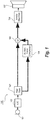
- Fig. 1 illustrates highly schematically a hearing aid system 100 according to a first embodiment of the invention.
- the hearing aid system 100 comprises an acoustical-electrical input transducer 101, and analog-digital converter (ADC) 102, a filter bank 103, an auditory nerve compressor 104, a first gain multiplier 105, an inverse filter bank 106, and an electrical-acoustical output transducer 107.
- ADC analog-digital converter
- the acoustical-electrical input transducer 101 provides an analog input signal that is fed to the ADC 102 for conversion to the digital domain, and the digital input signal is subsequently provided to the filter bank 103.
- the filter bank 103 splits the input signal into a plurality of frequency band signals (that may also simply be denoted frequency bands) and provides these to both the auditory nerve compressor 104 and the first gain multiplier 105. In the figures the plurality of frequency bands are illustrated by bold lines.
- the auditory nerve compressor 104 is adapted to relieve a hearing deficit of an individual hearing aid user by providing for each frequency band signal an appropriate gain as a function of a frequency band signal level that is determined by a signal level estimator (not shown in Fig. 1 for reasons of clarity).
- a signal level estimator not shown in Fig. 1 for reasons of clarity.
- This general functionality is well known within the art of hearing aid systems and compressor is a well-known term for a component providing this type of functionality. Further details concerning implementation of hearing aid system compressors may be found in e.g. WO-A1-2007/025569 and WO-A1-2010/028683 .
- the auditory nerve compressor 104 is specifically adapted to compress the input signal such that the provided acoustical output signal primarily activates healthy auditory nerve-fibres.
- the frequency dependent gains determined by the auditory nerve compressor 104 are applied to the respective corresponding frequency band signals using the first gain multiplier 105 hereby providing processed frequency band signals that subsequently are combined in the inverse filter bank 106 to provide an electrical output signal that is converted into an acoustical signal by the electrical-acoustical output transducer 107.
- the auditory nerve compressor 104 is adapted such that the provided output signal has a minimum signal level that corresponds to the hearing threshold (i.e. 0 dB SL), and such that the provided output signal has a maximum signal level, which is set to 40 dB SL or is selected from a range between 30 and 50 dB SL, which is expected to correspond to an upper level of the acoustical signal intensity levels that HSR nerve-fibres primarily respond to.
- a compression characteristic for the auditory nerve compressor 104 is therefore obtained based on a defined a minimum input signal level and a defined maximum input signal that are mapped onto respectively the minimum output level of the auditory nerve compressor 104 and onto the maximum output level of the auditory nerve compressor 104.
- the minimum input signal level is defined based on either the available dynamic range of the ADC or based on the noise floor of the input transducer.
- the maximum input signal level is defined based on the available dynamic range of the ADC for the lower range of the audible frequency spectrum and based on the output characteristics of the input transducer for the high frequency range of the audible frequency spectrum.
- the hearing aid system has only one frequency band. This solution may be advantageous with respect to simplicity of implementation and cost but generally a plurality of frequency bands are preferred. It is well known for a person skilled in the art of hearing aid systems that the number of available frequency bands, according to variations may vary between say 3 and up to say 1024.
- the provided frequency bands correspond to the so called auditory critical bands provided by the cochlea (the critical auditory bands are also denoted the Bark bands).
- the critical auditory bands are also denoted the Bark bands.
- the auditory nerve compressor 104 is adapted such that the provided output signal has a minimum signal level that corresponds to the hearing threshold (i.e. 0 dB SL), and adapted such that the provided output signal has a maximum signal level selected from a range between 50 and 80 dB SL which represents an upper end of a range of acoustical output signal intensity levels that primarily HSR and MSR auditory nerve fibres respond to.
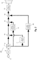
- Fig. 2 illustrates highly schematically a hearing aid system 200 according to a second embodiment of the invention.
- the hearing aid system 200 comprises all the components of Fig. 1 (and the numbering for these components are therefore maintained), and in addition hereto a speech enhancer 201, a noise reduction processor 202, a second gain multiplier 203, and a third gain multiplier 204.
- the gains determined by the auditory nerve compressor 104, the speech enhancer 201 and the noise reduction processor 202 are applied to the frequency bands provided by the filter bank 103 by the gain multipliers 105, 203 and 204 respectively hereby providing processed frequency bands that are combined in the inverse filter bank 106, wherefrom an output signal is provided to the electrical-acoustical output transducer 107.
- the noise reduction processor 202 is configured such that only negative frequency dependent noise suppressing gain values are determined.
- the negative noise suppression gain values are advantageous because they can be applied by the third gain multiplier 204 that is positioned downstream of the first gain multiplier 105 without the risk of providing output signal levels above the level that the intended auditory nerve-fibres primarily respond to.
- the speech enhancer 201 is typically implemented to determine both positive and negative frequency dependent speech enhancing gains and as a consequence hereof these gains are applied by the second gain multiplier 203 that is positioned upstream of the first gain multiplier 105.
- the speech enhancer 201 and the noise reduction processor 202 may benefit from more aggressive noise reduction algorithms or alternative processing schemes (which may also be denoted hearing aid features) directed at relieving the amount of sound that the auditory nerves are exposed to.
- alternative hearing aid features comprise frequency contrast enhancement and interleaved frequency band processing.
- the method of frequency contrast enhancement in a hearing aid system may be described by the steps of:
- the method of interleaved frequency band processing in a hearing aid system may be described by the steps of:
- the maximum output level for the auditory nerve compressor represents an upper end of a range of acoustical output signal intensity levels that primarily high-spontaneous rate and medium-spontaneous rate auditory nerve fibres respond to. This variation is advantageous in case only the LSR auditory nerve fibres have been damaged and probably most advantageous for hearing aid system users that do not suffer from an elevated threshold hearing deficit.
- the compression characteristic of the auditory nerve compressor comprises a knee point dividing the compression characteristic into a first part comprising the lower signal levels and a second part comprising the higher signal levels and wherein the compression ratio is larger in the second part than in the first part.
- other more or less complex compression characteristics may be applied.
- the input transducer is not of the acoustical-electrical type. Instead the input transducer is a wireless transceiver, whereby the inventive concepts of the present invention may also be applied in connection with e.g. digital audio streamed from a television or some other source of streamed audio.
- a method of fitting a hearing aid system wherein the hearing aid system is adapted to operate in accordance with the disclosed embodiments based on a previous test of whether the individual hearing aid system user suffers from an auditory neurodegeneration that only is present in some auditory nerve fibre types or only in some frequency bands.
- One such method that may be carried out in a plurality of different frequency bands, comprises the steps of:
- Another such method that may also be carried out in a plurality of different frequency bands, comprises the steps of:
- the range of acoustical output signal intensity levels is selected based on the individual user's preferences or the individual user's performance in speech intelligibility tests as a function of the range of acoustical output signal intensity levels.
- an optimum setting can be found as a compromise between the desire to avoid activating defect auditory fibres and the desire to provide an acoustical output signal level with a dynamic range that is not too limited.
- any of the disclosed embodiments of the invention may be varied by including one or more of the variations disclosed above with reference to another of the disclosed embodiments of the invention.
- the disclosed method embodiment may also be varied by including one or more of the hearing aid system variations.
Landscapes
- Health & Medical Sciences (AREA)
- General Health & Medical Sciences (AREA)
- Neurosurgery (AREA)
- Otolaryngology (AREA)
- Physics & Mathematics (AREA)
- Engineering & Computer Science (AREA)
- Acoustics & Sound (AREA)
- Signal Processing (AREA)
- Circuit For Audible Band Transducer (AREA)
- Soundproofing, Sound Blocking, And Sound Damping (AREA)
Claims (8)
- Procédé de fonctionnement d'un système de prothèse auditive (100, 200) d'un utilisateur de prothèse auditive comprenant les étapes de :- fourniture d'un signal d'entrée représentant un signal acoustique d'un transducteur d'entrée (101) du système de prothèse auditive (100, 200) ;- fourniture du signal d'entrée à un compresseur de nerf auditif (104) ;- sélection d'un niveau de sortie minimum pour le compresseur de nerf auditif (104), dans lequel le niveau de sortie minimum représente un niveau seuil auditif de 0 dB SL de l'utilisateur de prothèse auditive ;- sélection d'un niveau de sortie maximum pour le compresseur de nerf auditif (104), dans lequel le niveau de sortie maximum représente une extrémité supérieure d'une plage de niveaux d'intensité de signal de sortie acoustique, auxquels des fibres de nerf auditif à taux spontané élevé répondent principalement ou représente une extrémité supérieure d'une plage de niveaux d'intensité de signal de sortie acoustique, auxquels principalement des fibres de nerf auditif à taux spontané élevé et à taux spontané moyen répondent ;- définition d'un niveau de signal d'entrée minimum et d'un niveau de signal d'entrée maximum ;- fonctionnement du compresseur de nerf auditif (104) selon une caractéristique de compression, dans lequel le niveau de signal d'entrée minimum est mappé sur le niveau de sortie minimum du compresseur de nerf auditif (104), et dans lequel le niveau de signal d'entrée maximum est mappé sur le niveau de sortie maximum du compresseur de nerf auditif (104) ;- utilisation d'un signal de sortie dérivé du signal de sortie du compresseur de nerf auditif (104) pour entraîner un transducteur de sortie électrique acoustique du système de prothèse auditive; et dans lequel le niveau de sortie maximum pour le compresseur de nerf auditif (104) est sélectionné à partir d'une plage entre :
30 et 50 dB SL dans le cas où un trouble neurodégénératif auditif de l'utilisateur de prothèse auditive a été identifié pour les deux fibres de nerf auditif à taux spontané moyen et à taux spontané bas ou à partir d'une plage entre 50 et 80 dB SL dans le cas où un trouble neurodégénératif auditif de l'utilisateur de prothèse auditive a été identifié seulement pour des fibres de nerf auditif à taux spontané bas. - Procédé selon la revendication 1, comprenant les autres étapes de :- fractionnement du signal d'entrée en une pluralité de bandes de fréquence ;- fonctionnement du compresseur de nerf auditif (104) individuellement pour ladite pluralité de bandes de fréquence ; et- combinaison de la pluralité de bandes de fréquence qui ont été traitées par le compresseur de nerf auditif (104).
- Procédé selon l'une quelconque des revendications précédentes, dans lequel la caractéristique de compression comprend un point de coude divisant la caractéristique de compression en une première partie comprenant les niveaux de signal inférieurs et en une seconde partie comprenant les niveaux de signal supérieurs et dans lequel le rapport de compression est plus grand dans la seconde partie que dans la première partie.
- Procédé selon l'une quelconque des revendications précédentes, comprenant les autres étapes de :- traitement du signal d'entrée ou d'un signal de bande de fréquence avec un algorithme de réduction du bruit et/ou avec un algorithme d'amélioration de la parole et/ou avec au moins un algorithme dirigé spécifiquement pour réduire un trouble neurodégénératif auditif et déterminer ainsi au moins un gain à appliquer au signal d'entrée ou au moins un signal de bande de fréquence ;- application du gain déterminé au signal d'entrée ou à au moins un signal de bande de fréquence.
- Support de stockage lisible sur ordinateur présentant des instructions exécutables sur ordinateur, qui, lorsqu'elles sont exécutées, réalise le procédé selon l'une quelconque des revendications 1-4.
- Système de prothèse auditive (100, 200) pour un utilisateur de prothèse auditive comprenant :- un transducteur d'entrée (101) adapté pour fournir un signal d'entrée ;- un compresseur de nerf auditif (104) configuré pour traiter le signal d'entrée et fournir ainsi un signal de sortie, dans lequel le compresseur de nerf auditif (104) est configuré pour sélectionner un niveau de sortie minimum, dans lequel le niveau de sortie minimum représente un niveau seuil auditif de 0 dB SL de l'utilisateur de prothèse auditive dans lequel le compresseur de nerf auditif (104) est configuré pour sélectionner un niveau de sortie maximum, dans lequel le niveau de sortie maximum représente une extrémité supérieure d'une plage de niveaux d'intensité de signal de sortie acoustique, auxquels des fibres de nerf auditif à taux spontané élevé répondent principalement ou représente une extrémité supérieure d'une plage de niveaux d'intensité de signal de sortie acoustique, auxquels des fibres de nerf auditif à taux spontané élevé et à taux spontané moyen répondent principalement dans lequel le compresseur de nerf auditif est configuré pour définir un niveau de signal d'entrée minimum et un niveau de signal d'entrée maximum ; dans lequel le compresseur de nerf auditif est configuré pour être actionné selon une caractéristique de compression dans lequel le niveau de signal d'entrée minimum est mappé sur le niveau de sortie minimum du compresseur de nerf auditif (104), et dans lequel le niveau de signal d'entrée maximum est mappé sur le niveau de sortie maximum du compresseur de nerf auditif (104) ; et- un transducteur de sortie (104) adapté pour fournir un signal de sortie acoustique sur la base du signal de sortie à partir du compresseur de nerf auditif (104) ; et dans lequel
le signal de sortie à partir du compresseur de nerf auditif (104) représente un signal de sortie acoustique présentant des niveaux d'intensité confinés dans une plage de 0 dB SL et entre 30 et 50 dB SL dans le cas où un trouble neurodégénératif auditif de l'utilisateur de prothèse auditive a été identifié pour les deux fibres de nerf auditif à taux spontané moyen et à taux spontané bas ou dans une plage de 0 dB SL et entre 50 et 80 dB SL dans le cas où un trouble neurodégénératif auditif de l'utilisateur de prothèse auditive a été identifié seulement pour des fibres de nerf auditif à taux spontané bas. - Système de prothèse auditive (200) selon la revendication 6, comprenant en outre au moins un parmi- un premier processeur de signal numérique (202) adapté pour fournir une réduction de bruit,- un deuxième processeur de signal numérique (201) adapté pour améliorer la parole, et- un troisième processeur de signal numérique (104) adapté pour réduire spécifiquement un trouble neurodégénératif auditif.
- Procédé de pose d'un système de prothèse auditive d'un utilisateur de prothèse auditive comprenant les étapes d' :- identification d'un trouble neurodégénératif auditif ;- configuration d'un compresseur de système de prothèse auditive (104) par :- sélection d'un niveau de sortie minimum qui représente un niveau seuil auditif de 0 dB SL de l'utilisateur de prothèse auditive ;- sélection d'un niveau de sortie maximum à partir d'une plage entre 30 et 50 dB SL qui représente une extrémité supérieure d'une plage de niveaux d'intensité de signal de sortie acoustique, auxquels des fibres de nerf auditif à taux spontané élevé répondent principalement dans le cas où un trouble neurodégénératif auditif de l'utilisateur de prothèse auditive a été identifié pour les deux fibres de nerf auditif à taux spontané moyen et à taux spontané bas ;- sélection d'un niveau de sortie maximum à partir d'une plage entre 50 et 80 dB SL qui représente une extrémité supérieure d'une plage de niveaux d'intensité de signal de sortie acoustique, auxquels des fibres de nerf auditif à taux spontané élevé et à taux spontané moyen répondent principalement, dans le cas où un trouble neurodégénératif auditif de l'utilisateur de prothèse auditive a été identifié seulement pour des fibres de nerf auditif à taux spontané bas ;- définition d'un niveau de signal d'entrée minimum et d'un niveau de signal d'entrée maximum ; et dans lequel le compresseur comprend en outre une caractéristique de compression dans lequel le niveau de signal d'entrée minimum est mappé sur le niveau de sortie minimum et dans lequel le niveau de signal d'entrée maximum est mappé sur le niveau de sortie maximum.
Applications Claiming Priority (2)
| Application Number | Priority Date | Filing Date | Title |
|---|---|---|---|
| DKPA201600110 | 2016-02-24 | ||
| PCT/EP2017/052358 WO2017144253A1 (fr) | 2016-02-24 | 2017-02-03 | Procédé d'utilisation d'un système de prothèse auditive et système de prothèse auditive |
Publications (2)
| Publication Number | Publication Date |
|---|---|
| EP3420740A1 EP3420740A1 (fr) | 2019-01-02 |
| EP3420740B1 true EP3420740B1 (fr) | 2021-06-23 |
Family
ID=57960458
Family Applications (1)
| Application Number | Title | Priority Date | Filing Date |
|---|---|---|---|
| EP17702875.0A Active EP3420740B1 (fr) | 2016-02-24 | 2017-02-03 | Un procédé à la mise en oeuvre d'un système à prothèse auditive ainsi qu'un système à prothèse auditive |
Country Status (4)
| Country | Link |
|---|---|
| US (2) | US20170245064A1 (fr) |
| EP (1) | EP3420740B1 (fr) |
| DK (1) | DK3420740T3 (fr) |
| WO (1) | WO2017144253A1 (fr) |
Families Citing this family (2)
| Publication number | Priority date | Publication date | Assignee | Title |
|---|---|---|---|---|
| EP3852392B1 (fr) | 2020-01-17 | 2025-06-04 | Sonova AG | Compensation de pertes auditives cachées par atténuation de niveaux élevés de pression sonore |
| CN116208898B (zh) * | 2022-12-27 | 2025-12-02 | 南京未来脑科技有限公司 | 一种基于模型学习的听力补偿方法及设备 |
Family Cites Families (24)
| Publication number | Priority date | Publication date | Assignee | Title |
|---|---|---|---|---|
| US3115079A (en) | 1962-01-24 | 1963-12-24 | Optomechanisms Inc | Processing head for photographic mechanism |
| US4882762A (en) | 1988-02-23 | 1989-11-21 | Resound Corporation | Multi-band programmable compression system |
| US5278912A (en) * | 1991-06-28 | 1994-01-11 | Resound Corporation | Multiband programmable compression system |
| EP0855129A1 (fr) | 1995-10-10 | 1998-07-29 | AudioLogic, Incorporated | Prothese auditive a traitement de signaux numeriques et selection de strategie de traitement |
| JP2904272B2 (ja) * | 1996-12-10 | 1999-06-14 | 日本電気株式会社 | ディジタル補聴器、及びその補聴処理方法 |
| US6275596B1 (en) * | 1997-01-10 | 2001-08-14 | Gn Resound Corporation | Open ear canal hearing aid system |
| US20030007657A1 (en) | 2001-07-09 | 2003-01-09 | Topholm & Westermann Aps | Hearing aid with sudden sound alert |
| US7457757B1 (en) * | 2002-05-30 | 2008-11-25 | Plantronics, Inc. | Intelligibility control for speech communications systems |
| AU2003281984B2 (en) | 2003-11-24 | 2009-05-14 | Widex A/S | Hearing aid and a method of noise reduction |
| EP1865843A2 (fr) * | 2005-03-16 | 2007-12-19 | Sonicom, Inc. | Systeme et procede de batterie de tests pour l'evaluation d'une fonction auditive |
| US7813931B2 (en) * | 2005-04-20 | 2010-10-12 | QNX Software Systems, Co. | System for improving speech quality and intelligibility with bandwidth compression/expansion |
| WO2006133431A2 (fr) * | 2005-06-08 | 2006-12-14 | The Regents Of The University Of California | Procedes, dispositifs et systemes utilisant des algorithmes de traitement de signaux pour ameliorer l'intelligibilite de la parole et le confort d'ecoute |
| EP1932389B1 (fr) | 2005-09-01 | 2021-06-16 | Widex A/S | Procede de dispositif de commande de compresseurs de bandes partagees pour prothese auditive |
| KR20110050500A (ko) | 2008-09-10 | 2011-05-13 | 비덱스 에이/에스 | 보청기에서의 사운드 처리 방법 및 보청기 |
| EP2542301B1 (fr) | 2010-03-04 | 2014-03-12 | Fraunhofer Gesellschaft zur Förderung der angewandten Forschung e.V. | Production de signal de stimulation par électrode dans une prothèse auditive neurale |
| EP2560410B1 (fr) * | 2011-08-15 | 2019-06-19 | Oticon A/s | Contrôle de modulation de sortie dans un instrument auditif |
| DK2752031T3 (en) | 2011-09-01 | 2015-07-27 | Widex As | HEARING WITH ADAPTIVE NOISE REDUCTION AND PROCEDURE |
| US8831258B2 (en) * | 2012-04-05 | 2014-09-09 | Siemens Medical Instruments Pte. Ltd. | Method for restricting the output level in hearing apparatuses |
| US8913768B2 (en) * | 2012-04-25 | 2014-12-16 | Gn Resound A/S | Hearing aid with improved compression |
| WO2014025542A1 (fr) * | 2012-08-06 | 2014-02-13 | Father Flanagan's Boys' Home Doing Business As Boys Town National Research Hospital | Système et procédé de compression audio multi-bande |
| WO2014024050A2 (fr) | 2012-08-07 | 2014-02-13 | Cochlear Limited | Stratégie de réglage de paramètres de perception auditive pour une prothèse auditive |
| US10130809B2 (en) * | 2014-06-13 | 2018-11-20 | Nervana, LLC | Transcutaneous electrostimulator and methods for electric stimulation |
| US10080894B2 (en) | 2014-06-18 | 2018-09-25 | Northwestern University | Systems and methods for neuromodulation device coding with trans-species libraries |
| US9722562B1 (en) * | 2015-12-16 | 2017-08-01 | Google Inc. | Signal enhancements for audio |
-
2017
- 2017-02-03 WO PCT/EP2017/052358 patent/WO2017144253A1/fr not_active Ceased
- 2017-02-03 EP EP17702875.0A patent/EP3420740B1/fr active Active
- 2017-02-03 DK DK17702875.0T patent/DK3420740T3/da active
- 2017-02-17 US US15/435,509 patent/US20170245064A1/en not_active Abandoned
-
2019
- 2019-07-01 US US16/458,603 patent/US11070922B2/en active Active
Non-Patent Citations (1)
| Title |
|---|
| None * |
Also Published As
| Publication number | Publication date |
|---|---|
| US20170245064A1 (en) | 2017-08-24 |
| DK3420740T3 (da) | 2021-07-19 |
| WO2017144253A1 (fr) | 2017-08-31 |
| US11070922B2 (en) | 2021-07-20 |
| EP3420740A1 (fr) | 2019-01-02 |
| US20190327565A1 (en) | 2019-10-24 |
Similar Documents
| Publication | Publication Date | Title |
|---|---|---|
| US10158956B2 (en) | Method of fitting a hearing aid system, a hearing aid fitting system and a computerized device | |
| US10966032B2 (en) | Hearing apparatus with a facility for reducing a microphone noise and method for reducing microphone noise | |
| CN112822617B (zh) | 包括助听仪器的助听系统以及用于操作助听仪器的方法 | |
| US11070922B2 (en) | Method of operating a hearing aid system and a hearing aid system | |
| US10045132B2 (en) | Method of fitting a hearing aid system, a hearing aid fitting system and a computerized device | |
| EP4035420B1 (fr) | Procédé de fonctionnement d'un système audio de niveau d'oreille et système audio de niveau d'oreille | |
| US8948429B2 (en) | Amplification of a speech signal in dependence on the input level | |
| US11490216B2 (en) | Compensating hidden hearing losses by attenuating high sound pressure levels | |
| US20170245063A1 (en) | Hearing aid system and a method of operating a hearing aid system | |
| EP3395082B1 (fr) | Système de prothèse auditive et un procédé d'utilisation d'un système de prothèse auditive | |
| US10455332B2 (en) | Hearing aid system and a method of operating a hearing aid system | |
| US10212523B2 (en) | Hearing aid system and a method of operating a hearing aid system | |
| US20250310701A1 (en) | Hearing system |
Legal Events
| Date | Code | Title | Description |
|---|---|---|---|
| STAA | Information on the status of an ep patent application or granted ep patent |
Free format text: STATUS: UNKNOWN |
|
| STAA | Information on the status of an ep patent application or granted ep patent |
Free format text: STATUS: THE INTERNATIONAL PUBLICATION HAS BEEN MADE |
|
| PUAI | Public reference made under article 153(3) epc to a published international application that has entered the european phase |
Free format text: ORIGINAL CODE: 0009012 |
|
| STAA | Information on the status of an ep patent application or granted ep patent |
Free format text: STATUS: REQUEST FOR EXAMINATION WAS MADE |
|
| 17P | Request for examination filed |
Effective date: 20180924 |
|
| AK | Designated contracting states |
Kind code of ref document: A1 Designated state(s): AL AT BE BG CH CY CZ DE DK EE ES FI FR GB GR HR HU IE IS IT LI LT LU LV MC MK MT NL NO PL PT RO RS SE SI SK SM TR |
|
| AX | Request for extension of the european patent |
Extension state: BA ME |
|
| DAV | Request for validation of the european patent (deleted) | ||
| DAX | Request for extension of the european patent (deleted) | ||
| STAA | Information on the status of an ep patent application or granted ep patent |
Free format text: STATUS: EXAMINATION IS IN PROGRESS |
|
| 17Q | First examination report despatched |
Effective date: 20190626 |
|
| GRAP | Despatch of communication of intention to grant a patent |
Free format text: ORIGINAL CODE: EPIDOSNIGR1 |
|
| STAA | Information on the status of an ep patent application or granted ep patent |
Free format text: STATUS: GRANT OF PATENT IS INTENDED |
|
| INTG | Intention to grant announced |
Effective date: 20210407 |
|
| GRAS | Grant fee paid |
Free format text: ORIGINAL CODE: EPIDOSNIGR3 |
|
| GRAA | (expected) grant |
Free format text: ORIGINAL CODE: 0009210 |
|
| STAA | Information on the status of an ep patent application or granted ep patent |
Free format text: STATUS: THE PATENT HAS BEEN GRANTED |
|
| AK | Designated contracting states |
Kind code of ref document: B1 Designated state(s): AL AT BE BG CH CY CZ DE DK EE ES FI FR GB GR HR HU IE IS IT LI LT LU LV MC MK MT NL NO PL PT RO RS SE SI SK SM TR |
|
| REG | Reference to a national code |
Ref country code: GB Ref legal event code: FG4D |
|
| REG | Reference to a national code |
Ref country code: CH Ref legal event code: EP |
|
| REG | Reference to a national code |
Ref country code: DE Ref legal event code: R096 Ref document number: 602017040722 Country of ref document: DE Ref country code: AT Ref legal event code: REF Ref document number: 1405342 Country of ref document: AT Kind code of ref document: T Effective date: 20210715 |
|
| REG | Reference to a national code |
Ref country code: DK Ref legal event code: T3 Effective date: 20210714 |
|
| REG | Reference to a national code |
Ref country code: IE Ref legal event code: FG4D |
|
| REG | Reference to a national code |
Ref country code: LT Ref legal event code: MG9D |
|
| PG25 | Lapsed in a contracting state [announced via postgrant information from national office to epo] |
Ref country code: FI Free format text: LAPSE BECAUSE OF FAILURE TO SUBMIT A TRANSLATION OF THE DESCRIPTION OR TO PAY THE FEE WITHIN THE PRESCRIBED TIME-LIMIT Effective date: 20210623 Ref country code: LT Free format text: LAPSE BECAUSE OF FAILURE TO SUBMIT A TRANSLATION OF THE DESCRIPTION OR TO PAY THE FEE WITHIN THE PRESCRIBED TIME-LIMIT Effective date: 20210623 Ref country code: HR Free format text: LAPSE BECAUSE OF FAILURE TO SUBMIT A TRANSLATION OF THE DESCRIPTION OR TO PAY THE FEE WITHIN THE PRESCRIBED TIME-LIMIT Effective date: 20210623 Ref country code: BG Free format text: LAPSE BECAUSE OF FAILURE TO SUBMIT A TRANSLATION OF THE DESCRIPTION OR TO PAY THE FEE WITHIN THE PRESCRIBED TIME-LIMIT Effective date: 20210923 |
|
| REG | Reference to a national code |
Ref country code: AT Ref legal event code: MK05 Ref document number: 1405342 Country of ref document: AT Kind code of ref document: T Effective date: 20210623 |
|
| PG25 | Lapsed in a contracting state [announced via postgrant information from national office to epo] |
Ref country code: NO Free format text: LAPSE BECAUSE OF FAILURE TO SUBMIT A TRANSLATION OF THE DESCRIPTION OR TO PAY THE FEE WITHIN THE PRESCRIBED TIME-LIMIT Effective date: 20210923 Ref country code: RS Free format text: LAPSE BECAUSE OF FAILURE TO SUBMIT A TRANSLATION OF THE DESCRIPTION OR TO PAY THE FEE WITHIN THE PRESCRIBED TIME-LIMIT Effective date: 20210623 Ref country code: SE Free format text: LAPSE BECAUSE OF FAILURE TO SUBMIT A TRANSLATION OF THE DESCRIPTION OR TO PAY THE FEE WITHIN THE PRESCRIBED TIME-LIMIT Effective date: 20210623 Ref country code: LV Free format text: LAPSE BECAUSE OF FAILURE TO SUBMIT A TRANSLATION OF THE DESCRIPTION OR TO PAY THE FEE WITHIN THE PRESCRIBED TIME-LIMIT Effective date: 20210623 Ref country code: GR Free format text: LAPSE BECAUSE OF FAILURE TO SUBMIT A TRANSLATION OF THE DESCRIPTION OR TO PAY THE FEE WITHIN THE PRESCRIBED TIME-LIMIT Effective date: 20210924 |
|
| REG | Reference to a national code |
Ref country code: NL Ref legal event code: MP Effective date: 20210623 |
|
| PG25 | Lapsed in a contracting state [announced via postgrant information from national office to epo] |
Ref country code: ES Free format text: LAPSE BECAUSE OF FAILURE TO SUBMIT A TRANSLATION OF THE DESCRIPTION OR TO PAY THE FEE WITHIN THE PRESCRIBED TIME-LIMIT Effective date: 20210623 Ref country code: RO Free format text: LAPSE BECAUSE OF FAILURE TO SUBMIT A TRANSLATION OF THE DESCRIPTION OR TO PAY THE FEE WITHIN THE PRESCRIBED TIME-LIMIT Effective date: 20210623 Ref country code: PT Free format text: LAPSE BECAUSE OF FAILURE TO SUBMIT A TRANSLATION OF THE DESCRIPTION OR TO PAY THE FEE WITHIN THE PRESCRIBED TIME-LIMIT Effective date: 20211025 Ref country code: NL Free format text: LAPSE BECAUSE OF FAILURE TO SUBMIT A TRANSLATION OF THE DESCRIPTION OR TO PAY THE FEE WITHIN THE PRESCRIBED TIME-LIMIT Effective date: 20210623 Ref country code: EE Free format text: LAPSE BECAUSE OF FAILURE TO SUBMIT A TRANSLATION OF THE DESCRIPTION OR TO PAY THE FEE WITHIN THE PRESCRIBED TIME-LIMIT Effective date: 20210623 Ref country code: CZ Free format text: LAPSE BECAUSE OF FAILURE TO SUBMIT A TRANSLATION OF THE DESCRIPTION OR TO PAY THE FEE WITHIN THE PRESCRIBED TIME-LIMIT Effective date: 20210623 Ref country code: AT Free format text: LAPSE BECAUSE OF FAILURE TO SUBMIT A TRANSLATION OF THE DESCRIPTION OR TO PAY THE FEE WITHIN THE PRESCRIBED TIME-LIMIT Effective date: 20210623 Ref country code: SM Free format text: LAPSE BECAUSE OF FAILURE TO SUBMIT A TRANSLATION OF THE DESCRIPTION OR TO PAY THE FEE WITHIN THE PRESCRIBED TIME-LIMIT Effective date: 20210623 Ref country code: SK Free format text: LAPSE BECAUSE OF FAILURE TO SUBMIT A TRANSLATION OF THE DESCRIPTION OR TO PAY THE FEE WITHIN THE PRESCRIBED TIME-LIMIT Effective date: 20210623 |
|
| PG25 | Lapsed in a contracting state [announced via postgrant information from national office to epo] |
Ref country code: PL Free format text: LAPSE BECAUSE OF FAILURE TO SUBMIT A TRANSLATION OF THE DESCRIPTION OR TO PAY THE FEE WITHIN THE PRESCRIBED TIME-LIMIT Effective date: 20210623 |
|
| REG | Reference to a national code |
Ref country code: DE Ref legal event code: R097 Ref document number: 602017040722 Country of ref document: DE |
|
| PLBE | No opposition filed within time limit |
Free format text: ORIGINAL CODE: 0009261 |
|
| STAA | Information on the status of an ep patent application or granted ep patent |
Free format text: STATUS: NO OPPOSITION FILED WITHIN TIME LIMIT |
|
| 26N | No opposition filed |
Effective date: 20220324 |
|
| PG25 | Lapsed in a contracting state [announced via postgrant information from national office to epo] |
Ref country code: AL Free format text: LAPSE BECAUSE OF FAILURE TO SUBMIT A TRANSLATION OF THE DESCRIPTION OR TO PAY THE FEE WITHIN THE PRESCRIBED TIME-LIMIT Effective date: 20210623 |
|
| PG25 | Lapsed in a contracting state [announced via postgrant information from national office to epo] |
Ref country code: IT Free format text: LAPSE BECAUSE OF FAILURE TO SUBMIT A TRANSLATION OF THE DESCRIPTION OR TO PAY THE FEE WITHIN THE PRESCRIBED TIME-LIMIT Effective date: 20210623 |
|
| PG25 | Lapsed in a contracting state [announced via postgrant information from national office to epo] |
Ref country code: MC Free format text: LAPSE BECAUSE OF FAILURE TO SUBMIT A TRANSLATION OF THE DESCRIPTION OR TO PAY THE FEE WITHIN THE PRESCRIBED TIME-LIMIT Effective date: 20210623 |
|
| REG | Reference to a national code |
Ref country code: BE Ref legal event code: MM Effective date: 20220228 |
|
| GBPC | Gb: european patent ceased through non-payment of renewal fee |
Effective date: 20220203 |
|
| PG25 | Lapsed in a contracting state [announced via postgrant information from national office to epo] |
Ref country code: LU Free format text: LAPSE BECAUSE OF NON-PAYMENT OF DUE FEES Effective date: 20220203 |
|
| PG25 | Lapsed in a contracting state [announced via postgrant information from national office to epo] |
Ref country code: FR Free format text: LAPSE BECAUSE OF NON-PAYMENT OF DUE FEES Effective date: 20220228 |
|
| PG25 | Lapsed in a contracting state [announced via postgrant information from national office to epo] |
Ref country code: IE Free format text: LAPSE BECAUSE OF NON-PAYMENT OF DUE FEES Effective date: 20220203 Ref country code: GB Free format text: LAPSE BECAUSE OF NON-PAYMENT OF DUE FEES Effective date: 20220203 |
|
| PG25 | Lapsed in a contracting state [announced via postgrant information from national office to epo] |
Ref country code: BE Free format text: LAPSE BECAUSE OF NON-PAYMENT OF DUE FEES Effective date: 20220228 |
|
| PG25 | Lapsed in a contracting state [announced via postgrant information from national office to epo] |
Ref country code: HU Free format text: LAPSE BECAUSE OF FAILURE TO SUBMIT A TRANSLATION OF THE DESCRIPTION OR TO PAY THE FEE WITHIN THE PRESCRIBED TIME-LIMIT; INVALID AB INITIO Effective date: 20170203 |
|
| PG25 | Lapsed in a contracting state [announced via postgrant information from national office to epo] |
Ref country code: MK Free format text: LAPSE BECAUSE OF FAILURE TO SUBMIT A TRANSLATION OF THE DESCRIPTION OR TO PAY THE FEE WITHIN THE PRESCRIBED TIME-LIMIT Effective date: 20210623 Ref country code: CY Free format text: LAPSE BECAUSE OF FAILURE TO SUBMIT A TRANSLATION OF THE DESCRIPTION OR TO PAY THE FEE WITHIN THE PRESCRIBED TIME-LIMIT Effective date: 20210623 |
|
| PG25 | Lapsed in a contracting state [announced via postgrant information from national office to epo] |
Ref country code: MT Free format text: LAPSE BECAUSE OF FAILURE TO SUBMIT A TRANSLATION OF THE DESCRIPTION OR TO PAY THE FEE WITHIN THE PRESCRIBED TIME-LIMIT Effective date: 20210623 |
|
| PG25 | Lapsed in a contracting state [announced via postgrant information from national office to epo] |
Ref country code: TR Free format text: LAPSE BECAUSE OF FAILURE TO SUBMIT A TRANSLATION OF THE DESCRIPTION OR TO PAY THE FEE WITHIN THE PRESCRIBED TIME-LIMIT Effective date: 20210623 |
|
| REG | Reference to a national code |
Ref country code: CH Ref legal event code: U11 Free format text: ST27 STATUS EVENT CODE: U-0-0-U10-U11 (AS PROVIDED BY THE NATIONAL OFFICE) Effective date: 20260301 |
|
| PGFP | Annual fee paid to national office [announced via postgrant information from national office to epo] |
Ref country code: DE Payment date: 20260121 Year of fee payment: 10 Ref country code: DK Payment date: 20260121 Year of fee payment: 10 |
|
| PGFP | Annual fee paid to national office [announced via postgrant information from national office to epo] |
Ref country code: CH Payment date: 20260301 Year of fee payment: 10 |