EP3420832A1 - Helmlüftungsblende - Google Patents
Helmlüftungsblende Download PDFInfo
- Publication number
- EP3420832A1 EP3420832A1 EP18179749.9A EP18179749A EP3420832A1 EP 3420832 A1 EP3420832 A1 EP 3420832A1 EP 18179749 A EP18179749 A EP 18179749A EP 3420832 A1 EP3420832 A1 EP 3420832A1
- Authority
- EP
- European Patent Office
- Prior art keywords
- bezel
- hardware
- helmet
- opening
- anchor
- Prior art date
- Legal status (The legal status is an assumption and is not a legal conclusion. Google has not performed a legal analysis and makes no representation as to the accuracy of the status listed.)
- Granted
Links
Images



Classifications
-
- A—HUMAN NECESSITIES
- A42—HEADWEAR
- A42B—HATS; HEAD COVERINGS
- A42B3/00—Helmets; Helmet covers ; Other protective head coverings
- A42B3/003—Helmet covers
-
- A—HUMAN NECESSITIES
- A42—HEADWEAR
- A42B—HATS; HEAD COVERINGS
- A42B3/00—Helmets; Helmet covers ; Other protective head coverings
- A42B3/04—Parts, details or accessories of helmets
-
- A—HUMAN NECESSITIES
- A42—HEADWEAR
- A42B—HATS; HEAD COVERINGS
- A42B3/00—Helmets; Helmet covers ; Other protective head coverings
- A42B3/04—Parts, details or accessories of helmets
- A42B3/28—Ventilating arrangements
-
- A—HUMAN NECESSITIES
- A42—HEADWEAR
- A42B—HATS; HEAD COVERINGS
- A42B3/00—Helmets; Helmet covers ; Other protective head coverings
- A42B3/04—Parts, details or accessories of helmets
- A42B3/0406—Accessories for helmets
-
- A—HUMAN NECESSITIES
- A42—HEADWEAR
- A42B—HATS; HEAD COVERINGS
- A42B3/00—Helmets; Helmet covers ; Other protective head coverings
- A42B3/04—Parts, details or accessories of helmets
- A42B3/0406—Accessories for helmets
- A42B3/0433—Detecting, signalling or lighting devices
- A42B3/044—Lighting devices, e.g. helmets with lamps
-
- A—HUMAN NECESSITIES
- A42—HEADWEAR
- A42B—HATS; HEAD COVERINGS
- A42B3/00—Helmets; Helmet covers ; Other protective head coverings
- A42B3/04—Parts, details or accessories of helmets
- A42B3/0493—Aerodynamic helmets; Air guiding means therefor
-
- A—HUMAN NECESSITIES
- A42—HEADWEAR
- A42B—HATS; HEAD COVERINGS
- A42B3/00—Helmets; Helmet covers ; Other protective head coverings
- A42B3/04—Parts, details or accessories of helmets
- A42B3/06—Impact-absorbing shells, e.g. of crash helmets
- A42B3/062—Impact-absorbing shells, e.g. of crash helmets with reinforcing means
- A42B3/063—Impact-absorbing shells, e.g. of crash helmets with reinforcing means using layered structures
-
- A—HUMAN NECESSITIES
- A42—HEADWEAR
- A42B—HATS; HEAD COVERINGS
- A42B3/00—Helmets; Helmet covers ; Other protective head coverings
- A42B3/04—Parts, details or accessories of helmets
- A42B3/18—Face protection devices
- A42B3/22—Visors
- A42B3/227—Visors with sun visors, e.g. peaks above face opening
-
- A—HUMAN NECESSITIES
- A42—HEADWEAR
- A42B—HATS; HEAD COVERINGS
- A42B3/00—Helmets; Helmet covers ; Other protective head coverings
- A42B3/04—Parts, details or accessories of helmets
- A42B3/28—Ventilating arrangements
- A42B3/281—Air ducting systems
- A42B3/283—Air inlets or outlets, with or without closure shutters
-
- A—HUMAN NECESSITIES
- A42—HEADWEAR
- A42B—HATS; HEAD COVERINGS
- A42B3/00—Helmets; Helmet covers ; Other protective head coverings
- A42B3/04—Parts, details or accessories of helmets
- A42B3/06—Impact-absorbing shells, e.g. of crash helmets
- A42B3/061—External coatings, e.g. with light reflective material
-
- A—HUMAN NECESSITIES
- A42—HEADWEAR
- A42B—HATS; HEAD COVERINGS
- A42B3/00—Helmets; Helmet covers ; Other protective head coverings
- A42B3/04—Parts, details or accessories of helmets
- A42B3/08—Chin straps or similar retention devices
-
- A—HUMAN NECESSITIES
- A42—HEADWEAR
- A42B—HATS; HEAD COVERINGS
- A42B3/00—Helmets; Helmet covers ; Other protective head coverings
- A42B3/04—Parts, details or accessories of helmets
- A42B3/18—Face protection devices
- A42B3/22—Visors
Definitions
- aspects of this document relate generally to a helmet with a bezel, and more specifically to a helmet with a bezel positioned near a vent opening of the helmet.
- the usable surface space on the helmet body can be crowded because it often has helmet components such as a fit system and accessories such as a visor or camera attached.
- the available space on a typical bicycle helmet body is further reduced by vent openings distributed around the helmet body for ventilation purposes.
- the vent openings also weaken the strength of the vent wall around the openings. When a part is attached to the helmet near a vent opening, the vent wall often blows out from the force exerted by or through the part.
- a helmet may comprise a helmet body comprising an outer shell and an energy management layer inside the outer shell, the outer shell comprising a vent opening through the outer shell and the energy management layer, a fit system disposed within the energy management layer and coupled to the helmet body, a bezel separate from the outer shell and coupled to the helmet body at the vent opening, the bezel encircling the vent opening and having a hardware opening extending through the bezel and an anchor opening in the bezel adjacent the hardware opening, and a hardware retainer positioned behind and coupled to the bezel, the hardware retainer comprising a hardware receiving aperture aligned with the hardware opening, a hardware retainer cover coupled to a rear side of the hardware retainer, and an internally threaded nut aligned with the hardware opening and configured to receive and engage an accessory connector therein, the hardware retainer further comprising an anchor recess aligned with the anchor opening, wherein the bezel is in-molded into the energy management layer.
- the bezel may further comprise a footing extending behind the bezel.
- the hardware retainer may be coupled to the bezel by being snapped into the bezel.
- the bezel may comprise at least one prong extending rearward of the bezel adjacent the hardware opening, the hardware retainer comprises at least one prong receiver, and the hardware retainer is snapped to the bezel by the at least one prong being received into the at least one prong receiver.
- the accessory connector may be an accessory connector from one of a visor mechanism, a chin guard anchor, a light anchor, and an electronic accessory anchor.
- the hardware retainer cover may be hingedly coupled to the hardware retainer. At least one of the bezel and the hardware retainer may be configured to attach to the helmet with one or more of a strap anchor, a fit system, a comfort liner, and a multi-directional impact protection system.
- a bezel assembly for a helmet may comprise a bezel sized to encircle a vent opening of a helmet and having a hardware opening extending through the bezel and an anchor opening in the bezel adjacent the hardware opening, and a hardware retainer positioned behind and coupled to the bezel, the hardware retainer comprising a hardware receiving aperture aligned with the hardware opening and a hardware retainer cover coupled to a rear side of the hardware retainer, and the hardware retainer further comprising an anchor recess aligned with the anchor opening.
- the bezel may further comprise a footing extending behind the bezel.
- the hardware retainer may be coupled to the bezel by being snapped into the bezel.
- the bezel may comprise at least one prong extending rearward of the bezel adjacent the hardware opening, the hardware retainer may comprise at least one prong receiver, and the hardware retainer may be snapped to the bezel by the at least one prong being received into the at least one prong receiver.
- the accessory connector may be an accessory connector from one of a visor mechanism, a chin guard anchor, a light anchor, and an electronic accessory anchor.
- At least one of the bezel and the hardware retainer may be configured to attach to the helmet with one or more of a strap anchor, a fit system, a comfort liner, and a multi-directional impact protection system.
- a helmet may comprise a helmet body comprising an outer shell and an energy management layer inside the outer shell, the outer shell comprising a vent opening through the outer shell and the energy management layer, and a bezel separate from the outer shell and coupled to the helmet body at the vent opening, the bezel encircling the vent opening and having a hardware opening extending through the bezel and an anchor opening in the bezel adjacent the hardware opening, wherein the bezel is in-molded into the energy management layer.
- the helmet may further comprise a hardware retainer positioned behind and coupled to the bezel.
- the hardware retainer may comprise a hardware receiving aperture aligned with the hardware opening and a hardware retainer cover coupled to a rear side of the hardware retainer.
- the hardware retainer may further comprise an anchor recess aligned with the anchor opening.
- the bezel may further comprise a footing extending behind the bezel. The hardware retainer may be coupled to the bezel by being snapped into the bezel.
- the bezel may comprise at least one prong extending rearward of the bezel adjacent the hardware opening, the hardware retainer may comprise at least one prong receiver, and the hardware retainer may be snapped to the bezel by the at least one prong being received into the at least one prong receiver.
- the accessory connector may be an accessory connector from one of a visor mechanism, a chin guard anchor, a light anchor, and an electronic accessory anchor.
- the bezel may be configured to attach to the helmet with one or more of a strap anchor, a fit system, a comfort liner, and a multi-directional impact protection system.
- noun, term, or phrase is intended to be further characterized, specified, or narrowed in some way, such noun, term, or phrase will expressly include additional adjectives, descriptive terms, or other modifiers in accordance with the normal precepts of English grammar. Absent the use of such adjectives, descriptive terms, or modifiers, it is the intent that such nouns, terms, or phrases be given their plain, and ordinary English meaning to those skilled in the applicable arts as set forth above.
- Protective headgear and helmets have been used in a wide variety of applications and across a number of industries, including recreation, sports, athletics, construction, mining, and military defense, to prevent damage to users' heads and brains. Damage and injury to a user can be prevented or reduced by preventing hard objects, sharp objects, or both, from directly contacting the user's head, and also by absorbing, distributing, or otherwise managing energy of an impact between the object and the user's head. Straps or webbing are typically used to allow a user to releasably wear the helmet, and to ensure the helmet remains on the user's head during an impact.
- Helmets function to provide protection while minimizing interference with an activity.
- the shape of a helmet may be adapted to provide both protection and comfort (e.g. ventilation and size).
- Some helmets are made of two or more bodies of energy-absorbing material to form shapes that would be difficult, if not impossible, to achieve in a single molded piece.
- the protective shell can be made of an energy absorbing material, such as expanded polystyrene (EPS), expanded polyurethane (EPU), expanded polyolefin (EPO), expanded polypropylene (EPP), or other suitable material.
- the energy absorbing material can be part of a hard-shell helmet such as skate bucket helmets, motorcycle helmets, snow sport helmets, football helmets, batting helmets, catcher's helmets, or hockey helmets, and include an additional outer protective shell disposed outside, or over, the protective shell.
- the energy absorbing material can comprise one or more layers of energy absorbing material and provide more flexibility than available with conventional in-molded helmets.
- the energy absorbing material can be part of an in-molded helmet such as bicycle helmet or cycling helmet.
- the protective shell can comprise rigid materials such as EPS and EPU.
- An outer shell layer such as a layer of stamped polyethylene terephthalate (PET) or a polycarbonate shell, can be included on an outer surface of the protective shell of the helmet and be bonded directly to the expanding foam (e.g. EPS as it is expanding such that the foam is molded in the shell).
- PET stamped polyethylene terephthalate
- polycarbonate shell can be included on an outer surface of the protective shell of the helmet and be bonded directly to the expanding foam (e.g. EPS as it is expanding such that the foam is molded in the shell).
- a bezel that reinforces the vent opening of a helmet while also including a receptacle configured to receive an accessory connector therein or be used as a connector to connect other components of the helmet so that additional in-molded parts are eliminated.
- helmets While needing to withstand significant impact energy, helmets have many parts that need to be in-molded. Therefore, space on the helmet is at a premium. In conventional methods of helmet construction, parts generally perform one task. Integrating components together to serve multiple purposes and reinforce each other can reduce the space problem.
- Bezel assembly embodiments disclosed herein integrate several structures and purposes into a single assembly, decreasing the overall stack height of the components and the number of separate components in the helmet.
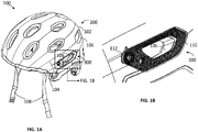
- a helmet 100 may comprise a helmet body 200 and a fit system 108.
- the helmet body 200 comprises an outer shell 102 and an energy management layer 104 inside the outer shell 102 with one or more vent openings 106 through the outer shell 102 and the energy management layer 104.
- the fit system 108 is disposed within the energy management layer 104 and coupled to the helmet body 200.
- the helmet 100 of FIG. 1A further comprises a vent bezel or bezel 110 and a hardware retainer 112 forming a bezel assembly 300.
- the bezel 110 is separate from the outer shell 102 and coupled to the helmet body 200 at the vent opening 106.
- the bezel 110 encircles the vent opening 106.
- FIG. 1A shows the front perspective view of a helmet 100 installed with a bezel assembly 300 and with the bezel 110 encircling a vent opening 106 of the helmet 100.
- FIG. 1B is a blow-up view of a portion of FIG. 1A .
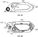
- the bezel 110 as illustrated in FIG. 2A , comprises a hardware opening 114 extending through the bezel 110 and an anchor opening 116 in the bezel adjacent the hardware opening 114 ( FIGs. 2A and 2B).
- FIG. 2A shows a front perspective view of a bezel 110
- FIG. 2B shows a rear perspective view of the bezel 110 shown in FIG. 2A .
- the bezel 110 includes a ring-like structure 146 so that the bezel 110 can encircle a vent opening 106.
- the shape of the ring-like structure may vary depending on the shape of the vent opening.
- a footing 148 extends behind the bezel 110. The footing 148 may be used to anchor the bezel 110 in the energy management layer 104.
- the footing 148 may comprise loops that allow EPS beads to flow around during the molding and anchor the bezel 110 in the energy management layer 104.
- the footing 148 may also be used to balance the force exerted on the bezel 110 at the hardware opening 114 and the anchor opening 116 when an accessory or a component of the helmet is attached to the helmet body through the bezel.
- the hardware retainer 112 illustrated in FIGs. 3A-3D comprises a hardware receiving aperture 118 and a hardware retainer cover 120.
- FIG. 3A is a front perspective view of a hardware retainer 112
- FIG. 3B is a front view of the hardware retainer 112 shown in FIG. 3A
- FIG. 3C is a rear view of the hardware retainer 112 shown in FIG. 3A
- FIG. 3D is a rear view of the hardware retainer 112 shown in FIG. 3A with the hardware retainer cover 120 uncovered from the hardware retainer 112.
- the hardware retainer cover 120 can be coupled to the rear side of the hardware retainer.
- the hardware retainer cover 120 may be hingedly coupled to the hardware retainer 112, or be detachable.
- the hardware retainer cover 120 may comprise one or more hinges 130, where one end of the hinge 130 is attached to the hardware retainer 112 and the other end of the hinge 130 is attached to the hardware retainer cover 120.
- the hardware retainer cover 120 may comprise one or more flaps 150 extending inward at its perimeter.
- the flaps 150 may comprise holes 152.
- the hardware receiving aperture 118 can have mating protrusions 154 along its perimeter.
- the hardware retainer cover 120 is configured to engage the hardware retainer 112 and cover the hardware receiving aperture 118 by the engagement of the protrusions 154 through the holes 152 with the flaps 150 ( FIGs. 3C and 3D ).
- a hardware retainer 112 may further comprise a nut 122, internally threaded with internal threads 134 ( FIGs. 4A-4B ).
- the nut 122 can be positioned in the hardware receiving aperture 118 and covered by the hardware retainer cover 120 ( FIGs. 3C-3D ).
- the hardware retainer 112 may include an anchor recess 124 ( FIGs. 3A and 3B ).
- the hardware retainer 112 in the embodiment of FIGs. 3C-3D is assembled with a bezel 110 (see FIG. 1B )
- the hardware retainer 112 can be positioned behind and coupled to the bezel 110 ( FIG. 1B ).
- the hardware receiving aperture 118 and the nut 122 may be aligned with the hardware opening 114 of the bezel 110.
- the anchor recess 124 of the hardware retainer 112 is aligned with the anchor opening 116 of the bezel 110.
- the hardware retainer 112 may be coupled to the bezel 110 by being snapped into the bezel 110.
- the bezel 110 further comprises at least one prong 126 extending rearward of the bezel 110 adjacent the hardware opening 114 ( FIG.
- the hardware retainer 112 further comprises at least one prong receiver 128 ( FIGs. 3A-3D ).
- the hardware retainer 112 can be snapped to the bezel 110 by the at least one prong 126 being received into the least one prong receiver 128.
- the bezel and/or the bezel assembly may be constructed as separate parts and the parts may be assembled together through mechanisms such as being snapped, being glued, or other mechanisms know to a person skilled in the art. In some instances, the bezel and/or the bezel assembly may be constructed as one piece.
- a bezel and/or a bezel assembly can be used to connect components of the helmet to the helmet body.
- Helmet components such as a fit system, a strap anchor, a comfort liner, or a multi-directional impact protection system may be attached to the helmet at the bezel through pins, magnets, glue, or any other mechanisms known to a person skilled in the art.
- the hardware retainer cover 120 may further comprise a connector for attaching a fit system, a strap anchor, a comfort liner, or a multi-directional impact protection system onto the helmet.
- the connector can also be configured to attach the components directly to the bezel.
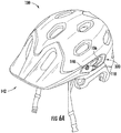
- FIG. 6A shows the front perspective view of an example accessory 142 being attached to a helmet at one of the vent openings 106 through a bezel assembly 300 and an accessory connector 140.
- FIG. 6B shows a front perspective view of the example accessory 142 shown in FIG. 6A .
- the nut 122 of the hardware retainer 112 is configured to receive and engage an accessory connector 140 therein.
- an accessory connector 140 may be an accessory connector from one of at least a visor mechanism, a chin guard anchor, a light anchor, and an electronic accessory anchor. By example, it can also be used to connect accessories such as a visor, electronic accessories like cameras, chin guards, flash lights, and head lamps to the helmet.
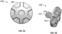
- An accessory connector 140 may comprise a threaded portion 132, which comprises external threads 156, and a cap 144.
- the accessory connector 140 engages the nut 122 through the external threads 156 of the accessory connector 140 being engaged with the internal threads 134 of the nut 122.
- the accessory may comprise a slot 138 that allows the threaded portion 132 of the accessory connector 140 to pass through and allow the external threads 156 of the accessory connector 140 to engage the internal threads 134 of the nut 122 in the hardware retainer 112 ( FIGs. 5A-6B ).
- the slot 138 may be configured to define the range of adjustment for the accessory 142.
- the accessory connector 140 comprises a cap 144.
- the perimeter of the cap 144 can be larger than the perimeter of the slot 138 on the accessory 142 so that the cap 144 blocks the accessory 142 from disengaging from the helmet 100.
- the accessory 142 comprises a post 136 extending from the accessory 142.
- the post 136 can be inserted into the anchor opening 116 of the bezel 110 and further into the anchor recess 124 of the hardware retainer 112.
- the post 136 comprises a spring pin geometry that locks the post 136 in when inserted into the bezel 110 and the hardware retainer 112 ( FIG. 6B ).
- the post 136 can be used to limit the accessory 142 from rotating around the accessory connector 140 after the accessory 142 has been attached to the helmet 100.
- the post 136 can also provide an additional attachment point for the accessory 142 and strengthen the attachment of the accessory 142 to the helmet 100.
- an accessory to the helmet through the bezel through the engagement of internal and external threads is only an example of attaching an accessary to the helmet through the bezel.
- An accessory can be attached to the helmet through the bezel through mechanisms other than the engagement of the internal and external threads, such as the accessory connector can be snapped into the hardware opening, or the accessory can be attached to the bezel through pins, magnets, glue, or any other mechanisms known to a person skilled in the art.
- the bezel can be used alone or together with the hardware retainer, and the hardware opening of the bezel can be used alone or together with the anchor recess of the bezel.
- implementations and implementing components may comprise any components, models, types, materials, versions, quantities, and/or the like as is known in the art for such systems and implementing components, consistent with the intended operation.
Landscapes
- Physics & Mathematics (AREA)
- Fluid Mechanics (AREA)
- Helmets And Other Head Coverings (AREA)
Applications Claiming Priority (1)
| Application Number | Priority Date | Filing Date | Title |
|---|---|---|---|
| US15/638,121 US10786027B1 (en) | 2017-06-29 | 2017-06-29 | Helmet vent bezel |
Publications (2)
| Publication Number | Publication Date |
|---|---|
| EP3420832A1 true EP3420832A1 (de) | 2019-01-02 |
| EP3420832B1 EP3420832B1 (de) | 2020-03-18 |
Family
ID=62791554
Family Applications (1)
| Application Number | Title | Priority Date | Filing Date |
|---|---|---|---|
| EP18179749.9A Active EP3420832B1 (de) | 2017-06-29 | 2018-06-26 | Helmlüftungsblende |
Country Status (3)
| Country | Link |
|---|---|
| US (2) | US10786027B1 (de) |
| EP (1) | EP3420832B1 (de) |
| CN (1) | CN109198771B (de) |
Families Citing this family (1)
| Publication number | Priority date | Publication date | Assignee | Title |
|---|---|---|---|---|
| USD1097344S1 (en) * | 2024-06-03 | 2025-10-07 | Poc Sweden Ab | Cycling helmet |
Citations (6)
| Publication number | Priority date | Publication date | Assignee | Title |
|---|---|---|---|---|
| US5309576A (en) * | 1991-06-19 | 1994-05-10 | Bell Helmets Inc. | Multiple density helmet body compositions to strengthen helmet |
| US6711751B1 (en) * | 2001-03-08 | 2004-03-30 | K-2 Corporation | Mounting system for helmets |
| US20140189939A1 (en) * | 2013-01-07 | 2014-07-10 | Strategic Sports Limited | Bicycle Helmet With Visor |
| US20150143616A1 (en) * | 2013-11-22 | 2015-05-28 | K-2 Corporation | Tool-free accessory retaining device for a helmet |
| US20160007668A1 (en) * | 2014-05-18 | 2016-01-14 | Trek Bicycle Corporation | Helmet vent adapter |
| EP3095342A1 (de) * | 2015-05-18 | 2016-11-23 | Mavic S.A.S. | Sporthelm |
Family Cites Families (29)
| Publication number | Priority date | Publication date | Assignee | Title |
|---|---|---|---|---|
| US4404690A (en) * | 1981-08-21 | 1983-09-20 | Amer Sport International Inc. | Hockey helmet |
| JPH0454180Y2 (de) * | 1987-05-12 | 1992-12-18 | ||
| JPH0165822U (de) * | 1987-10-20 | 1989-04-27 | ||
| JPH0635684B2 (ja) * | 1990-10-03 | 1994-05-11 | 昭栄化工株式会社 | 乗車用ヘルメット |
| JPH04135920U (ja) * | 1991-05-31 | 1992-12-17 | 昭栄化工株式会社 | ヘルメツトの空気取入装置 |
| JP2517117Y2 (ja) * | 1993-08-03 | 1996-11-13 | 昭栄化工株式会社 | ヘルメットの空気取入装置 |
| US5394566A (en) * | 1993-12-14 | 1995-03-07 | Hong Jin Crown America, Inc. | Cold weather ventilation system for faceshield defogging |
| US6009561A (en) * | 1998-08-26 | 2000-01-04 | Bell Sports Inc. | Helmet with rotatable accessory mount and method of making the same |
| US6009562A (en) * | 1998-08-26 | 2000-01-04 | Bell Sports, Inc. | Helmet with accessory mounting apparatus and method of making the same |
| EP1396200B1 (de) * | 2001-06-12 | 2006-12-06 | Shoei Co., Ltd. | Helm |
| DE10319500A1 (de) * | 2002-05-01 | 2004-01-15 | Riddell Inc., Chicago | Football-Helm |
| US20040064873A1 (en) * | 2002-05-29 | 2004-04-08 | Muskovitz David T. | In-mold protective helmet having integrated ventilation system |
| KR100468348B1 (ko) * | 2003-03-24 | 2005-01-27 | 주식회사 홍진에이치제이씨 | 헬멧용 에어벤트 |
| US7207071B2 (en) * | 2004-06-18 | 2007-04-24 | Fox Racing, Inc. | Ventilated helmet system |
| US8020219B2 (en) * | 2005-07-01 | 2011-09-20 | Bell Sports, Inc. | Strap anchor system and method |
| JP4895544B2 (ja) * | 2005-07-15 | 2012-03-14 | 株式会社Shoei | フルフェイス型ヘルメット |
| JP4848155B2 (ja) * | 2005-08-19 | 2011-12-28 | 株式会社Shoei | ヘルメット |
| ES2446420T3 (es) * | 2009-10-07 | 2014-03-07 | Nolangroup S.P.A. | Casco de seguridad con mentonera alzable |
| US20120017358A1 (en) * | 2010-07-22 | 2012-01-26 | Wingo-Princip Management LLC | Protective helmet |
| US8683617B2 (en) * | 2011-01-19 | 2014-04-01 | Smith Optics, Inc. | Multi-component helmet with ventilation shutter |
| US10492555B2 (en) * | 2012-07-31 | 2019-12-03 | Rm Soldier Systems, Ltd. | Helmet mounting system |
| IL230802A0 (en) * | 2014-02-03 | 2014-09-30 | Cardo Systems Inc | Adapter for attaching an audio kit to the helmet |
| US11317673B2 (en) * | 2014-05-29 | 2022-05-03 | Strategic Sports Limited | Attachment and attachment system for a helmet |
| US9955049B2 (en) * | 2014-07-31 | 2018-04-24 | Bell Sports, Inc. | Helmet with integrated electronics and helmet visor controls |
| US9675129B2 (en) * | 2014-12-01 | 2017-06-13 | Bern Unlimited, Inc. | Helmet with vent opening control |
| CN107529845A (zh) * | 2015-02-28 | 2018-01-02 | 路明科技香港有限公司 | 头盔与头盔系统 |
| EP3340643A1 (de) * | 2016-12-21 | 2018-06-27 | Safariland, LLC | Schienenverbinder für ohrmuschelaufhängungsanordnung |
| US10918152B2 (en) * | 2017-05-01 | 2021-02-16 | 9609385 Canada Inc. | Light-emitting beacon |
| DE102021110198A1 (de) * | 2020-04-30 | 2021-11-04 | Dräger Safety AG & Co. KGaA | Schutzhelm mit einem Adapter und Verfahren zur lösbaren Befestigung eines Moduls |
-
2017
- 2017-06-29 US US15/638,121 patent/US10786027B1/en active Active
-
2018
- 2018-06-26 EP EP18179749.9A patent/EP3420832B1/de active Active
- 2018-06-27 CN CN201810681372.3A patent/CN109198771B/zh active Active
-
2020
- 2020-09-28 US US17/035,449 patent/US11672295B2/en active Active
Patent Citations (6)
| Publication number | Priority date | Publication date | Assignee | Title |
|---|---|---|---|---|
| US5309576A (en) * | 1991-06-19 | 1994-05-10 | Bell Helmets Inc. | Multiple density helmet body compositions to strengthen helmet |
| US6711751B1 (en) * | 2001-03-08 | 2004-03-30 | K-2 Corporation | Mounting system for helmets |
| US20140189939A1 (en) * | 2013-01-07 | 2014-07-10 | Strategic Sports Limited | Bicycle Helmet With Visor |
| US20150143616A1 (en) * | 2013-11-22 | 2015-05-28 | K-2 Corporation | Tool-free accessory retaining device for a helmet |
| US20160007668A1 (en) * | 2014-05-18 | 2016-01-14 | Trek Bicycle Corporation | Helmet vent adapter |
| EP3095342A1 (de) * | 2015-05-18 | 2016-11-23 | Mavic S.A.S. | Sporthelm |
Also Published As
| Publication number | Publication date |
|---|---|
| US10786027B1 (en) | 2020-09-29 |
| US20210007431A1 (en) | 2021-01-14 |
| US11672295B2 (en) | 2023-06-13 |
| CN109198771B (zh) | 2021-07-27 |
| EP3420832B1 (de) | 2020-03-18 |
| CN109198771A (zh) | 2019-01-15 |
Similar Documents
| Publication | Publication Date | Title |
|---|---|---|
| US10398187B1 (en) | Adjustable elastomeric helmet multi-liner retainer and method of assembling multi-liner helmet | |
| US12582188B2 (en) | Protective helmet with multiple pseudo-spherical energy management liners | |
| US10743603B2 (en) | Clip-free helmet visors | |
| US9713355B2 (en) | Mechanical fasteners for shock-absorbing helmets | |
| US11812812B2 (en) | Helmet goggle strap holder | |
| EP3459376A1 (de) | Ineinandergreifende, gemeinsam geformte helm-energiemanagementauskleidung | |
| US11589631B2 (en) | Helmet with integrated shoulder pad | |
| US20190216156A1 (en) | Helmet strap attachment method and device | |
| EP3364801B1 (de) | Helm mit kinnbügelkragen | |
| US11672295B2 (en) | Helmet vent bezel | |
| US20230292873A1 (en) | Improvements in or relating to helmets |
Legal Events
| Date | Code | Title | Description |
|---|---|---|---|
| PUAI | Public reference made under article 153(3) epc to a published international application that has entered the european phase |
Free format text: ORIGINAL CODE: 0009012 |
|
| STAA | Information on the status of an ep patent application or granted ep patent |
Free format text: STATUS: THE APPLICATION HAS BEEN PUBLISHED |
|
| AK | Designated contracting states |
Kind code of ref document: A1 Designated state(s): AL AT BE BG CH CY CZ DE DK EE ES FI FR GB GR HR HU IE IS IT LI LT LU LV MC MK MT NL NO PL PT RO RS SE SI SK SM TR |
|
| AX | Request for extension of the european patent |
Extension state: BA ME |
|
| STAA | Information on the status of an ep patent application or granted ep patent |
Free format text: STATUS: REQUEST FOR EXAMINATION WAS MADE |
|
| 17P | Request for examination filed |
Effective date: 20190520 |
|
| RBV | Designated contracting states (corrected) |
Designated state(s): AL AT BE BG CH CY CZ DE DK EE ES FI FR GB GR HR HU IE IS IT LI LT LU LV MC MK MT NL NO PL PT RO RS SE SI SK SM TR |
|
| GRAP | Despatch of communication of intention to grant a patent |
Free format text: ORIGINAL CODE: EPIDOSNIGR1 |
|
| STAA | Information on the status of an ep patent application or granted ep patent |
Free format text: STATUS: GRANT OF PATENT IS INTENDED |
|
| INTG | Intention to grant announced |
Effective date: 20191008 |
|
| GRAS | Grant fee paid |
Free format text: ORIGINAL CODE: EPIDOSNIGR3 |
|
| GRAA | (expected) grant |
Free format text: ORIGINAL CODE: 0009210 |
|
| STAA | Information on the status of an ep patent application or granted ep patent |
Free format text: STATUS: THE PATENT HAS BEEN GRANTED |
|
| AK | Designated contracting states |
Kind code of ref document: B1 Designated state(s): AL AT BE BG CH CY CZ DE DK EE ES FI FR GB GR HR HU IE IS IT LI LT LU LV MC MK MT NL NO PL PT RO RS SE SI SK SM TR |
|
| REG | Reference to a national code |
Ref country code: GB Ref legal event code: FG4D |
|
| REG | Reference to a national code |
Ref country code: DE Ref legal event code: R096 Ref document number: 602018003097 Country of ref document: DE |
|
| REG | Reference to a national code |
Ref country code: AT Ref legal event code: REF Ref document number: 1244886 Country of ref document: AT Kind code of ref document: T Effective date: 20200415 Ref country code: IE Ref legal event code: FG4D |
|
| PG25 | Lapsed in a contracting state [announced via postgrant information from national office to epo] |
Ref country code: FI Free format text: LAPSE BECAUSE OF FAILURE TO SUBMIT A TRANSLATION OF THE DESCRIPTION OR TO PAY THE FEE WITHIN THE PRESCRIBED TIME-LIMIT Effective date: 20200318 Ref country code: NO Free format text: LAPSE BECAUSE OF FAILURE TO SUBMIT A TRANSLATION OF THE DESCRIPTION OR TO PAY THE FEE WITHIN THE PRESCRIBED TIME-LIMIT Effective date: 20200618 Ref country code: RS Free format text: LAPSE BECAUSE OF FAILURE TO SUBMIT A TRANSLATION OF THE DESCRIPTION OR TO PAY THE FEE WITHIN THE PRESCRIBED TIME-LIMIT Effective date: 20200318 |
|
| REG | Reference to a national code |
Ref country code: NL Ref legal event code: MP Effective date: 20200318 |
|
| PG25 | Lapsed in a contracting state [announced via postgrant information from national office to epo] |
Ref country code: BG Free format text: LAPSE BECAUSE OF FAILURE TO SUBMIT A TRANSLATION OF THE DESCRIPTION OR TO PAY THE FEE WITHIN THE PRESCRIBED TIME-LIMIT Effective date: 20200618 Ref country code: GR Free format text: LAPSE BECAUSE OF FAILURE TO SUBMIT A TRANSLATION OF THE DESCRIPTION OR TO PAY THE FEE WITHIN THE PRESCRIBED TIME-LIMIT Effective date: 20200619 Ref country code: HR Free format text: LAPSE BECAUSE OF FAILURE TO SUBMIT A TRANSLATION OF THE DESCRIPTION OR TO PAY THE FEE WITHIN THE PRESCRIBED TIME-LIMIT Effective date: 20200318 Ref country code: LV Free format text: LAPSE BECAUSE OF FAILURE TO SUBMIT A TRANSLATION OF THE DESCRIPTION OR TO PAY THE FEE WITHIN THE PRESCRIBED TIME-LIMIT Effective date: 20200318 Ref country code: SE Free format text: LAPSE BECAUSE OF FAILURE TO SUBMIT A TRANSLATION OF THE DESCRIPTION OR TO PAY THE FEE WITHIN THE PRESCRIBED TIME-LIMIT Effective date: 20200318 |
|
| REG | Reference to a national code |
Ref country code: LT Ref legal event code: MG4D |
|
| PG25 | Lapsed in a contracting state [announced via postgrant information from national office to epo] |
Ref country code: NL Free format text: LAPSE BECAUSE OF FAILURE TO SUBMIT A TRANSLATION OF THE DESCRIPTION OR TO PAY THE FEE WITHIN THE PRESCRIBED TIME-LIMIT Effective date: 20200318 |
|
| PG25 | Lapsed in a contracting state [announced via postgrant information from national office to epo] |
Ref country code: IS Free format text: LAPSE BECAUSE OF FAILURE TO SUBMIT A TRANSLATION OF THE DESCRIPTION OR TO PAY THE FEE WITHIN THE PRESCRIBED TIME-LIMIT Effective date: 20200718 Ref country code: LT Free format text: LAPSE BECAUSE OF FAILURE TO SUBMIT A TRANSLATION OF THE DESCRIPTION OR TO PAY THE FEE WITHIN THE PRESCRIBED TIME-LIMIT Effective date: 20200318 Ref country code: RO Free format text: LAPSE BECAUSE OF FAILURE TO SUBMIT A TRANSLATION OF THE DESCRIPTION OR TO PAY THE FEE WITHIN THE PRESCRIBED TIME-LIMIT Effective date: 20200318 Ref country code: SK Free format text: LAPSE BECAUSE OF FAILURE TO SUBMIT A TRANSLATION OF THE DESCRIPTION OR TO PAY THE FEE WITHIN THE PRESCRIBED TIME-LIMIT Effective date: 20200318 Ref country code: CZ Free format text: LAPSE BECAUSE OF FAILURE TO SUBMIT A TRANSLATION OF THE DESCRIPTION OR TO PAY THE FEE WITHIN THE PRESCRIBED TIME-LIMIT Effective date: 20200318 Ref country code: PT Free format text: LAPSE BECAUSE OF FAILURE TO SUBMIT A TRANSLATION OF THE DESCRIPTION OR TO PAY THE FEE WITHIN THE PRESCRIBED TIME-LIMIT Effective date: 20200812 Ref country code: EE Free format text: LAPSE BECAUSE OF FAILURE TO SUBMIT A TRANSLATION OF THE DESCRIPTION OR TO PAY THE FEE WITHIN THE PRESCRIBED TIME-LIMIT Effective date: 20200318 Ref country code: SM Free format text: LAPSE BECAUSE OF FAILURE TO SUBMIT A TRANSLATION OF THE DESCRIPTION OR TO PAY THE FEE WITHIN THE PRESCRIBED TIME-LIMIT Effective date: 20200318 |
|
| REG | Reference to a national code |
Ref country code: AT Ref legal event code: MK05 Ref document number: 1244886 Country of ref document: AT Kind code of ref document: T Effective date: 20200318 |
|
| REG | Reference to a national code |
Ref country code: DE Ref legal event code: R097 Ref document number: 602018003097 Country of ref document: DE |
|
| PLBE | No opposition filed within time limit |
Free format text: ORIGINAL CODE: 0009261 |
|
| STAA | Information on the status of an ep patent application or granted ep patent |
Free format text: STATUS: NO OPPOSITION FILED WITHIN TIME LIMIT |
|
| PG25 | Lapsed in a contracting state [announced via postgrant information from national office to epo] |
Ref country code: MC Free format text: LAPSE BECAUSE OF FAILURE TO SUBMIT A TRANSLATION OF THE DESCRIPTION OR TO PAY THE FEE WITHIN THE PRESCRIBED TIME-LIMIT Effective date: 20200318 Ref country code: ES Free format text: LAPSE BECAUSE OF FAILURE TO SUBMIT A TRANSLATION OF THE DESCRIPTION OR TO PAY THE FEE WITHIN THE PRESCRIBED TIME-LIMIT Effective date: 20200318 Ref country code: DK Free format text: LAPSE BECAUSE OF FAILURE TO SUBMIT A TRANSLATION OF THE DESCRIPTION OR TO PAY THE FEE WITHIN THE PRESCRIBED TIME-LIMIT Effective date: 20200318 Ref country code: IT Free format text: LAPSE BECAUSE OF FAILURE TO SUBMIT A TRANSLATION OF THE DESCRIPTION OR TO PAY THE FEE WITHIN THE PRESCRIBED TIME-LIMIT Effective date: 20200318 Ref country code: AT Free format text: LAPSE BECAUSE OF FAILURE TO SUBMIT A TRANSLATION OF THE DESCRIPTION OR TO PAY THE FEE WITHIN THE PRESCRIBED TIME-LIMIT Effective date: 20200318 |
|
| 26N | No opposition filed |
Effective date: 20201221 |
|
| PG25 | Lapsed in a contracting state [announced via postgrant information from national office to epo] |
Ref country code: PL Free format text: LAPSE BECAUSE OF FAILURE TO SUBMIT A TRANSLATION OF THE DESCRIPTION OR TO PAY THE FEE WITHIN THE PRESCRIBED TIME-LIMIT Effective date: 20200318 |
|
| PG25 | Lapsed in a contracting state [announced via postgrant information from national office to epo] |
Ref country code: LU Free format text: LAPSE BECAUSE OF NON-PAYMENT OF DUE FEES Effective date: 20200626 |
|
| REG | Reference to a national code |
Ref country code: BE Ref legal event code: MM Effective date: 20200630 |
|
| PG25 | Lapsed in a contracting state [announced via postgrant information from national office to epo] |
Ref country code: IE Free format text: LAPSE BECAUSE OF NON-PAYMENT OF DUE FEES Effective date: 20200626 |
|
| PG25 | Lapsed in a contracting state [announced via postgrant information from national office to epo] |
Ref country code: BE Free format text: LAPSE BECAUSE OF NON-PAYMENT OF DUE FEES Effective date: 20200630 Ref country code: SI Free format text: LAPSE BECAUSE OF FAILURE TO SUBMIT A TRANSLATION OF THE DESCRIPTION OR TO PAY THE FEE WITHIN THE PRESCRIBED TIME-LIMIT Effective date: 20200318 |
|
| REG | Reference to a national code |
Ref country code: CH Ref legal event code: PL |
|
| PG25 | Lapsed in a contracting state [announced via postgrant information from national office to epo] |
Ref country code: LI Free format text: LAPSE BECAUSE OF NON-PAYMENT OF DUE FEES Effective date: 20210630 Ref country code: CH Free format text: LAPSE BECAUSE OF NON-PAYMENT OF DUE FEES Effective date: 20210630 |
|
| PG25 | Lapsed in a contracting state [announced via postgrant information from national office to epo] |
Ref country code: TR Free format text: LAPSE BECAUSE OF FAILURE TO SUBMIT A TRANSLATION OF THE DESCRIPTION OR TO PAY THE FEE WITHIN THE PRESCRIBED TIME-LIMIT Effective date: 20200318 Ref country code: MT Free format text: LAPSE BECAUSE OF FAILURE TO SUBMIT A TRANSLATION OF THE DESCRIPTION OR TO PAY THE FEE WITHIN THE PRESCRIBED TIME-LIMIT Effective date: 20200318 Ref country code: CY Free format text: LAPSE BECAUSE OF FAILURE TO SUBMIT A TRANSLATION OF THE DESCRIPTION OR TO PAY THE FEE WITHIN THE PRESCRIBED TIME-LIMIT Effective date: 20200318 |
|
| PG25 | Lapsed in a contracting state [announced via postgrant information from national office to epo] |
Ref country code: MK Free format text: LAPSE BECAUSE OF FAILURE TO SUBMIT A TRANSLATION OF THE DESCRIPTION OR TO PAY THE FEE WITHIN THE PRESCRIBED TIME-LIMIT Effective date: 20200318 Ref country code: AL Free format text: LAPSE BECAUSE OF FAILURE TO SUBMIT A TRANSLATION OF THE DESCRIPTION OR TO PAY THE FEE WITHIN THE PRESCRIBED TIME-LIMIT Effective date: 20200318 |
|
| PGFP | Annual fee paid to national office [announced via postgrant information from national office to epo] |
Ref country code: GB Payment date: 20240627 Year of fee payment: 7 |
|
| PGFP | Annual fee paid to national office [announced via postgrant information from national office to epo] |
Ref country code: DE Payment date: 20250627 Year of fee payment: 8 |
|
| PGFP | Annual fee paid to national office [announced via postgrant information from national office to epo] |
Ref country code: FR Payment date: 20250625 Year of fee payment: 8 |
|
| GBPC | Gb: european patent ceased through non-payment of renewal fee |
Effective date: 20250626 |
|
| PG25 | Lapsed in a contracting state [announced via postgrant information from national office to epo] |
Ref country code: GB Free format text: LAPSE BECAUSE OF NON-PAYMENT OF DUE FEES Effective date: 20250626 |