EP3420896B1 - Vorrichtung, verfahren und computerprogramme zur überwachung des pulses eines benutzers - Google Patents
Vorrichtung, verfahren und computerprogramme zur überwachung des pulses eines benutzers Download PDFInfo
- Publication number
- EP3420896B1 EP3420896B1 EP17179215.3A EP17179215A EP3420896B1 EP 3420896 B1 EP3420896 B1 EP 3420896B1 EP 17179215 A EP17179215 A EP 17179215A EP 3420896 B1 EP3420896 B1 EP 3420896B1
- Authority
- EP
- European Patent Office
- Prior art keywords
- pulse
- user
- monitoring module
- piezoelectric transducer
- time period
- Prior art date
- Legal status (The legal status is an assumption and is not a legal conclusion. Google has not performed a legal analysis and makes no representation as to the accuracy of the status listed.)
- Active
Links
Images


Classifications
-
- A—HUMAN NECESSITIES
- A61—MEDICAL OR VETERINARY SCIENCE; HYGIENE
- A61B—DIAGNOSIS; SURGERY; IDENTIFICATION
- A61B5/00—Measuring for diagnostic purposes; Identification of persons
- A61B5/02—Detecting, measuring or recording for evaluating the cardiovascular system, e.g. pulse, heart rate, blood pressure or blood flow
- A61B5/024—Measuring pulse rate or heart rate
- A61B5/02438—Measuring pulse rate or heart rate with portable devices, e.g. worn by the patient
-
- A—HUMAN NECESSITIES
- A61—MEDICAL OR VETERINARY SCIENCE; HYGIENE
- A61B—DIAGNOSIS; SURGERY; IDENTIFICATION
- A61B5/00—Measuring for diagnostic purposes; Identification of persons
- A61B5/02—Detecting, measuring or recording for evaluating the cardiovascular system, e.g. pulse, heart rate, blood pressure or blood flow
- A61B5/024—Measuring pulse rate or heart rate
- A61B5/02444—Details of sensor
-
- A—HUMAN NECESSITIES
- A61—MEDICAL OR VETERINARY SCIENCE; HYGIENE
- A61B—DIAGNOSIS; SURGERY; IDENTIFICATION
- A61B5/00—Measuring for diagnostic purposes; Identification of persons
- A61B5/48—Other medical applications
- A61B5/486—Biofeedback
-
- A—HUMAN NECESSITIES
- A61—MEDICAL OR VETERINARY SCIENCE; HYGIENE
- A61B—DIAGNOSIS; SURGERY; IDENTIFICATION
- A61B5/00—Measuring for diagnostic purposes; Identification of persons
- A61B5/68—Arrangements of detecting, measuring or recording means, e.g. sensors, in relation to patient
- A61B5/6801—Arrangements of detecting, measuring or recording means, e.g. sensors, in relation to patient specially adapted to be attached to or worn on the body surface
- A61B5/6802—Sensor mounted on worn items
- A61B5/681—Wristwatch-type devices
-
- A—HUMAN NECESSITIES
- A61—MEDICAL OR VETERINARY SCIENCE; HYGIENE
- A61B—DIAGNOSIS; SURGERY; IDENTIFICATION
- A61B5/00—Measuring for diagnostic purposes; Identification of persons
- A61B5/68—Arrangements of detecting, measuring or recording means, e.g. sensors, in relation to patient
- A61B5/6801—Arrangements of detecting, measuring or recording means, e.g. sensors, in relation to patient specially adapted to be attached to or worn on the body surface
- A61B5/6813—Specially adapted to be attached to a specific body part
- A61B5/6824—Arm or wrist
-
- A—HUMAN NECESSITIES
- A61—MEDICAL OR VETERINARY SCIENCE; HYGIENE
- A61B—DIAGNOSIS; SURGERY; IDENTIFICATION
- A61B5/00—Measuring for diagnostic purposes; Identification of persons
- A61B5/74—Details of notification to user or communication with user or patient; User input means
- A61B5/7455—Details of notification to user or communication with user or patient; User input means characterised by tactile indication, e.g. vibration or electrical stimulation
-
- A—HUMAN NECESSITIES
- A61—MEDICAL OR VETERINARY SCIENCE; HYGIENE
- A61B—DIAGNOSIS; SURGERY; IDENTIFICATION
- A61B5/00—Measuring for diagnostic purposes; Identification of persons
- A61B5/74—Details of notification to user or communication with user or patient; User input means
- A61B5/746—Alarms related to a physiological condition, e.g. details of setting alarm thresholds or avoiding false alarms
-
- A—HUMAN NECESSITIES
- A61—MEDICAL OR VETERINARY SCIENCE; HYGIENE
- A61B—DIAGNOSIS; SURGERY; IDENTIFICATION
- A61B7/00—Instruments for auscultation
- A61B7/02—Stethoscopes
- A61B7/04—Electric stethoscopes
Definitions
- Examples of the disclosure relate to apparatus, methods and computer programs for monitoring a user's pulse.
- examples of the disclosure relate to apparatus, methods and computer programs for monitoring a user's pulse using a wearable device.
- Apparatus for monitoring a user's pulse are known. Such apparatus may be found in wearable devices such as watches or sensors that can be attached to the user. Such apparatus can be used in a wide range of applications such as health monitoring applications or fitness applications. Once a pulse has been detected it is useful to provide the user with information indicative of the detected pulse.
- US 2016/346501 A1 relates to a wearable device capable of altering the heart rate of a user by providing a rhythmic tactile stimulus to the user.
- US 2014/077945 A1 relates to a biological information notification apparatus having a vibration section which can provide vibrations to the human body corresponding to the heartbeat of the user when the heartbeat is within a predetermined range.
- WO 2016/123129 A1 relates to a wearable device for providing haptic indications to a wearer which can indicate approach to, arrival at, or departure from a threshold heart rate.
- US 2010/152545 A1 relates to a haptic monitoring system which senses a user or individual's vital information and generates haptic feedback in response to the vital information.
- the haptic feedback may emulate vital signs in real-time.
- an apparatus comprising: a pulse monitoring module comprising detecting means for detecting a user's pulse and feedback means for providing haptic feedback to the user indicative of the detected pulse wherein the detecting means and the feedback means share at least one piezoelectric transducer; and control circuitry arranged to control the pulse monitoring module so that during a first time period the at least one piezoelectric transducer is arranged to detect a user's pulse and during a second time period the at least one piezoelectric transducer is arranged to provide haptic feedback indicative of the detected pulse.
- the second time period may run sequentially to the first time period.
- the controlling circuitry may be arranged to control the pulse monitoring module so that the pulse monitoring module alternates between a first time period in which the detecting means is arranged to detect a user's pulse and a second time period in which the feedback means is arranged to provide haptic feedback indicative of the detected pulse.
- the feedback means may be arranged to deform a portion of the apparatus so that the deformation of the apparatus can be perceived via a user's sense of touch.
- the controlling circuitry may be arranged to control to feedback means to control the frequency of the deformation of the apparatus to correspond to the frequency of the user's detected pulse.
- the pulse monitoring module may comprise a plurality of piezoelectric transducers and at least a portion of the controlling circuitry is positioned between two of the plurality of piezoelectric transducers.
- the pulse monitoring module may be provided within a metallic housing.
- the metallic housing provides a bias electrode for the at least one piezoelectric transducer within the pulse monitoring module.
- the apparatus may comprise an elastomeric portion wherein the elastomeric portion is positioned within the apparatus so that when the apparatus is worn by the user the elastomeric portion contacts the user's skin.
- the apparatus may comprise a cavity and wherein the cavity has a size and shape arranged to amplify audio pulse signals from a user.
- the apparatus may comprise a mass arranged to amplify the haptic feedback of the feedback means.
- the apparatus may comprise a coupling means wherein the coupling means enables the apparatus to be worn by a user.
- the coupling means may comprise a flexible substrate.
- a wearable electronic device comprising an apparatus as described above.
- a method comprising: controlling a pulse monitoring module, comprising at least one piezoelectric transducer, so that, during a first time period, the pulse monitoring module is arranged to detect a user's pulse using the at least one piezoelectric transducer; and controlling the pulse monitoring module so that, during a second time period, the pulse monitoring module is arranged to provide haptic feedback indicative of the detected pulse using the at least one piezoelectric transducer.
- a computer program that, when run on a processor, causes controlling a pulse monitoring module, comprising at least one piezoelectric transducer, so that, during a first time period, the pulse monitoring module is arranged to detect a user's pulse using the at least one piezoelectric transducer; and controlling the pulse monitoring module so that, during a second time period, the pulse monitoring module is arranged to provide haptic feedback indicative of the detected pulse using the at least one piezoelectric transducer.
- the Figures illustrate apparatus 1, methods and controlling circuitry 5 which enable a user's pulse to be monitored and also enable feedback indicative of the user's pulse to be provided to the user.
- the apparatus 1 comprises a pulse monitoring module 3 which comprises both detecting means 7 and feedback means 9.
- the detecting means 7 can be arranged to detect the user's pulse and the feedback means 9 can be arranged to provide haptic feedback indicative of the detected pulse.
- This enables the same module to function as both a detector and a feedback provider. As a single module can perform two functions this reduces the volume of the apparatus 1 which makes it easier for the apparatus 1 to be integrated into a wearable device.
- the apparatus 1 is arranged to provide haptic feedback to the user indicative of their pulse. The haptic feedback may require a smaller cognitive load from the user compared to visual and/or audio feedback.
- Fig. 1 schematically illustrates an example apparatus 1 according to examples of the disclosure.
- the apparatus 1 comprises a pulse monitoring module 3 and controlling circuitry 5.
- the pulse monitoring module 3 comprises detecting means 7 for detecting a user's pulse and feedback means 9 for providing haptic feedback to the user indicative of a detected pulse.
- the detecting means 7 may comprise any means which may be arranged to detect a pulse of a user and provide an output signal indicative of the detected pulse.
- the detecting means 7 may comprise one or more detectors.
- the detecting means 7 comprises a transducer which may be arranged to detect the audio signal of the user's pulse.
- the transducer comprises a piezoelectric transducer which may be arranged to deform when the audio signal of the pulse is detected. The deformation of the piezoelectric transducer may cause an output signal to be provided to the controlling circuitry 5.
- the frequency of the deformations of the piezoelectric transducer provides an indication of the frequency of the user's pulse.
- the detecting means 7 may be positioned within the apparatus 1 so that, in use, the detecting means 7 is positioned adjacent to, or close to, a user's skin. In some examples at least a portion of the detecting means 7 may be provided on the surface of the apparatus 1. The detecting means 7 may be provided on a surface of the apparatus 1 which is positioned adjacent to a user's skin when the apparatus 1 is worn by a user.
- the feedback means 9 may comprise any means which may be arranged to provide a haptic feedback to the user.
- the feedback means 9 may comprise one or more actuators.
- the haptic feedback may comprise any feedback which can be perceived via the user's sense of touch.
- the haptic feedback may comprise a deformation of at least a portion of the apparatus 1.
- the deformation may comprise the deformation of the feedback means 9.
- the deformation may comprise the deformation of other components of the apparatus 1 in addition to the deformation of the feedback means 9.
- the deformation has a magnitude which is large enough (above one micrometer) for the deformation to be perceived via a user's sense of touch.
- the deformation of at least a portion of the apparatus 1 is periodic so that the apparatus 1 is deformed and then returned to an un-deformed state with a frequency controlled by the controlling circuitry 5.
- the frequency of the deformations may be controlled to be the same as, or provide an indication of, the frequency of the detected pulse of the user.
- the feedback means 9 may comprise any means which may be arranged to change shape in response to an input electrical signal.
- the feedback means 9 may comprise a piezoelectric transducer, electroactive polymer or any other suitable material.
- the feedback means 9 comprises a piezoelectric transducer which is shared with the detecting means 7 so that during a first time period T 1 the piezoelectric transducer acts to detect a user's pulse and during a second time period T 2 the piezoelectric transducer acts to provide a haptic indication of the frequency of the user's pulse.
- the first time period T 1 and the second time period T 2 may have different durations. In some examples the first time period T 1 may be longer than the second time period T 2 .
- the first time period T 1 may be a lot longer than the second time period T 2 , for example, the second time period T 2 could be within a range of 5 to 50ms while the first time period T 1 could be several seconds. Other ranges could be used in other examples of the disclosure.
- the feedback means 9 is positioned within the apparatus 1 so that when the feedback means is deformed the deformation can be sensed by the user via their sense of touch.
- the feedback means 9, or at least a portion of the feedback means 9 is provided on a surface of the apparatus 1.
- the feedback means 9, or at least a portion of the feedback means 9 is provided on a surface of the apparatus 1 which may be positioned adjacent to the user's skin when the apparatus 1 is worn by the user.
- the apparatus 1 may comprise means for amplifying the haptic feedback provided by the feedback means 9.
- the apparatus 1 may comprise means for amplifying the deformation of the feedback means 9 so that the deformation can be sensed by a user.
- the means for amplifying the haptic feedback could comprise any suitable means.
- it may comprise a mass positioned within the appartaus1 and coupled to the feedback means 9 so as to increase the deformation of the apparatus 1.
- the mass could comprise at least some of the controlling circuitry 5. In such examples the mass would be provided internally within the apparatus 1.
- the mass could be provided on the outer surface of the apparatus 1. For instance a disc or other component could be provided on the outer surface of the apparatus and coupled to the feedback means 9 to increase the deformation of the feedback means.
- the controlling circuitry 5 may comprise any means which may be arranged to control the pulse monitoring module 3. Examples of controlling circuitry 5 are shown in more detail in Fig. 5 .
- the controlling circuitry 5 is coupled to the detecting means 7 so that a control signal from the controlling circuitry 5 can be provided to the detecting means 7 and an output signal from the detecting means 7 can be provided to the controlling circuitry 5.
- the control signal may be used to control the time periods at which the detecting means 7 is arranged to detect the user's pulse.
- the output signal from the detecting means may be used by the controlling circuitry 5 to determine the frequency of the user's pulse.
- the controlling circuitry 5 is also coupled to the feedback means 9 so that a control signal from the controlling circuitry 5 can be provided to the feedback means 9.
- the control signal may be used to control the time periods at which the feedback means 9 is arranged to provide the haptic feedback.
- the control signal from the controlling circuitry 5 may also be used to control parameters of the haptic feedback.
- the parameters could comprise the frequency of the deformations, the amplitude of the deformations or any other suitable parameters.
- the controlling circuitry 5 may control the frequency of the deformations of the haptic feedback to provide an indication of the frequency of the user's pulse. In some examples the controlling circuitry 5 may control the frequency of the deformations of the haptic feedback so that the haptic feedback has the same frequency as the user's pulse. In other examples the frequency of the deformations could be used to provide information about the user's pulse but does not need to be the same frequency.
- controlling circuitry 5 could control the amplitude of the deformations of the haptic feedback to provide an indication of the frequency of the user's pulse. In some examples the controlling circuitry 5 may control the amplitude of the deformations so that the amplitude of the deformation is proportional to the frequency of the detected pulse.
- controlling circuitry 5 could control the amplitude of the deformations of the haptic feedback so that different amplitudes could be used in different applications. For example, if the apparatus 1 is being used by a user currently involved in physical activity the amplitude of the deformations could be increased to make it easier for the haptic feedback to be perceived by the user. Conversely if the apparatus 1 is being used by a user who is currently resting then deformations having a smaller amplitude could be used.
- the controlling circuitry 5 is arranged to provide control signals to the pulse control module 3 to cause the pulse control module 3 to sequentially switch between a pulse detecting mode of operation and a feedback mode of operation.
- the controlling circuitry 5 may cause the pulse control module 3 to switch between the two modes of operation after a predetermined time period.
- the controlling circuitry 5 may cause the pulse control module 3 to alternate between the two modes of operation
- Figs. 2A to 2D schematically illustrate another example apparatus 1 according to an example of the disclosure.
- Fig. 2A illustrates a cross section of the apparatus 1
- Fig. 2B illustrates a plan view of a first piezoelectric transducer
- Fig. 2C illustrates a side view of a first piezoelectric transducer
- Fig. 2D illustrates a plan view of piezoelectric transducer embedded within a metallic housing.
- the example apparatus 1 of Figs. 2A to 2d comprises a pulse monitoring module 3 and controlling circuitry 5.
- the apparatus 1 also comprises coupling means 11.
- the pulse monitoring module comprises detecting means 7 and feedback means 9 which may be as described above.
- the detecting means 7 comprises a first piezoelectric transducer 21.
- the piezoelectric transducer 21 has a circular shape and is arranged to expand and contract radially in response to an audio input signal such as the pulse of a user.
- the detecting means 7 also comprises a cavity 19.
- the cavity 19 is positioned adjacent to the piezoelectric transducer 22.
- the cavity 19 may be an acoustic cavity which may be sized and shaped so as to amplify an audio signal.
- the cavity 19 may increase the sensitivity of the detecting means 7.
- the feedback means 9 comprises a first piezoelectric transducer 21 and a second piezoelectric transducer 22.
- the first piezoelectric transducer 21 forms part of the detecting means 7 so that the feedback means 9 and the detecting means 7 share a common piezoelectric transducer 21.
- the common piezoelectric transducer 21 is controlled to operate in different modes depending on whether the pulse monitoring module is operating in a detecting mode or a feedback mode. Having the feedback means 9 and the detecting means 7 share a common piezoelectric transducer 21 reduces the number of components required within the apparatus 1. This may enable the size of the apparatus 1 to be reduced which may make the apparatus 1 easier to integrate into a wearable electronic device.
- the first piezoelectric transducer 21 and the second piezoelectric transducer 22 may be arranged to change shape in response to an input electric signal.
- both the first piezoelectric transducer 21 and the second piezoelectric transducer 22 have a circular cross section and are arranged to expand and contract radially in response to a control signal from the controlling circuitry 5.
- the first piezoelectric transducer 21 is provided on a first surface of the apparatus 1 and the second piezoelectric transducer 22 is provided on a second surface of the apparatus 1 so that a space is provided between the two piezoelectric transducers 21, 22.
- the controlling circuitry 5 may be provided within the space between the two piezoelectric transducers 21, 22. This may reduce the volume required for the apparatus 1 which may make the apparatus 1 easier to integrate into wearable electronic device. This may also enable the controlling circuitry to act as a vibrating mass. This may increase the amplitude of the deformations of the apparatus 1 and/or the force applied to the piezoelectric transducers 21, 22 which may make the deformations easier for a user to sense.
- the pulse monitoring module 3 is provided within a metallic housing 23.
- the metallic housing 23 may provide means for coupling the first piezoelectric transducer 21 to the second piezoelectric transducer 22.
- the metallic housing 23 could be made of steel or any other suitable metal.
- the metallic housing 23 also has a circular cross section corresponding to the shape of the piezoelectric transducers 21, 22.
- the piezoelectric transducers 21, 22 may be embedded tightly within the metallic housing 23.
- the metallic housing comprises inner fixtures 17, 15 which are coupled to the respective piezoelectric transducers 21, 22.
- the inner fixtures 17, 15 may provide flexible substrates which supports the piezoelectric transducers 21, 22.
- the inner fixtures 17, 15 may be arranged to deform as the piezoelectric transducers 21, 22 are deformed.
- the inner fixtures 17, 15 may also be arranged to provide a bias electrode for the piezoelectric transducers 21, 22. As the inner fixtures provide both a support and a bias electrode this reduces the number of components within the apparatus 1 which may enable a smaller apparatus 1 to be provided.
- the metallic housing 23 also comprises a projection 20.
- the projection 20 is provided on the inner surface of the metallic housing 23 between the first piezoelectric transducer 21 and the second piezoelectric transducer 22.
- the projection 20 may be arranged to couple the first piezoelectric transducer 21 and the second piezoelectric transducer 22 together.
- the apparatus 1 also comprise an elastomeric portion 27.
- the elastomeric portion 27 is provided on an end of the metallic housing 23 so that in use the elastomeric portion 27 is in contact with a user's skin.
- the elastomeric portion 27 may provide a soft portion to contact the user's skin which may make the apparatus 1 more comfortable for a user to use.
- the elastomeric portion 27 could be made of rubber or any other suitable material.
- the apparatus 1 also comprises coupling means 11.
- the coupling means 11 may comprise any means which may enable the appartaus1 to be coupled to a user.
- the coupling means 11 comprises a strap.
- the strap could be fastened around a user's wrist, chest or any other suitable part of the user's body.
- the coupling means 11 could comprise a necklace or lanyard which could be worn around the user's neck.
- the coupling means 11 could comprise an adhesive portion which may enable the apparatus 1 to be adhered to the user's body.
- the coupling means could comprise an item of clothing which could be worn by the user.
- the apparatus 1 also comprises a damping portion 25.
- the damping portion 25 is provided between the pulse monitoring module 3 and the coupling means 11.
- the damping portion 25 comprises an elastomeric material which may be arranged to absorb vibrational energy from the pulse monitoring module 3.
- the damping portion 25 acts to prevent movement of the pulse monitoring module 3 being transferred to other portions of the apparatus 1. This may act to prevent the apparatus 1 from moving around the user's body when the apparatus 1 is in use. This may also act to protect other components of the apparatus 1. For instance it may prevent any electronic components in other portions of the apparatus 1 from being deformed.
- the controlling circuitry 5 controls the apparatus 1 to operate in either a detecting mode of operation or a feedback mode of operation.
- the first piezoelectric transducer 21 is arranged to detect the audio pulse signal and provide an output signal indicative of the detected audio pulse.
- the output signal is provided to the controlling circuitry 5 so that the controlling circuitry 5 can determine the frequency of the pulse and any other suitable parameters.
- the controlling circuitry 5 When the apparatus 1 is in a feedback mode of operation the controlling circuitry 5 provides a control signal to both the first piezoelectric transducer 21 and the second piezoelectric transducer 22. This causes the deformation of both of the piezoelectric transducers 21, 22. In the example of Figs. 2A to 2D the piezoelectric transducers are driven in opposing directions so that they move in opposite directions as indicated by the arrows 29. This provides for a larger amplitude of the deformation which may make the haptic feedback easier for a user to sense.
- the controlling circuitry 5 drives the piezoelectric transducers 21, 22 with a frequency determined by the frequency, or other suitable parameter, of the detected pulse.
- the frequency of the deformations of the piezoelectric transducers 21, 22 may be the same as the frequency of the user's pulse. This enables the user to be provided with information about their pulse without requiring significant cognitive load. As the user is provided with haptic feedback about their pulse they do not need to look at a screen. This could be useful in applications where the user is performing other activities. For instance, if the user is running or performing some other fitness activity or gaming it may be inconvenient or uncomfortable for them to look at a screen to check their heart rate.
- the haptic feedback enables the user to be provided with the information they need without having to interrupt their fitness or gaming activity. Also as the feedback is provided haptically this does not interrupt other people around the user. For instance, where the user in a public place there is no audio output that may interrupt other people. This also enables the feedback to be kept private and only provided to the user of the apparatus 1.
- Figs. 3A and 3B schematically illustrate cross section of example apparatus 1 according to examples of the disclosure.
- the example apparatus 1 of Figs. 3A and 3B also comprises controlling circuitry 5, a pulse detection module 3 and coupling means 11 which may be as described above.
- the feedback means 9 and the detecting means 7 are provided as the same component.
- the controlling circuitry 5 acts to control the component to sequentially operate in either a feedback mode of operation or a detecting mode of operation.
- the feedback means 9 is provided as a separate component to the detecting means 7.
- the controlling circuitry 5 acts to control the respective components to sequentially operate in either a feedback mode of operation or a detecting mode of operation.
- the controlling circuitry 5 may act to enable the apparatus 1 to alternate between a feedback mode of operation and a detecting mode of operation.
- the feedback means 9 and the detecting means 7 comprise circular piezoelectric transducers 21, 22.
- the piezoelectric transducers 21 could be provided as strips which may be arranged to expand and contract in the different modes of operation.
- Fig. 4 illustrates an example method which could be used to control the example apparatus 1. The method could be implemented in any of the example apparatus 1 as described above.
- the method comprises, at block 41, controlling a pulse monitoring module 3 so that during a first time period T 1 the pulse monitoring module 3 is arranged to detect a user's pulse and, at block 43, controlling the pulse monitoring module 3 so that during a second time period T 2 the pulse monitoring module 3 is arranged to provide haptic feedback indicative of the detected pulse.
- Block 43 may be implemented immediately after block 41 has been completed. In some examples there may be no time interval between block 41 and block 43. In other examples of the disclosure there may be a small time interval between block 41 and block 43.
- Blocks 41 and 43 may last for different durations.
- the first time period T 1 may be longer than the second time period T 2 .
- the first time period T 1 may be a lot longer than the second time period T 2 , for example, the second time period T 2 could be within a range of 5 to 50ms while the first time period T 1 could be several seconds. Other ranges could be used in other examples of the disclosure.
- Block 41 and 43 may be repeated.
- the blocks may be repeated continuously so that as soon as a time period for providing haptic feedback has ended a time period for detecting the pulse begins.
- the parameters of haptic feedback may correspond to the parameters of the pulse detected in the detecting time period immediately preceding the current feedback time period. This ensures that any delay in the feedback provided to the user is minimised.
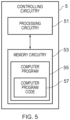
- Fig. 5 illustrates example controlling circuity 5 which may be provided within the example apparatus 1 as described above.
- the controlling circuitry 5 illustrated in Fig. 5 may be a chip or a chip-set.
- the controlling circuitry 5 may provide means for performing the example methods or at least part of the example methods of Fig. 4 .
- the controlling circuitry 5 comprises processing circuitry 51 and memory circuitry 53.
- the processing circuitry 51 may be configured to read from and write to the memory circuitry 53.
- the processing circuitry 51 may comprise one or more processors.
- the processing circuitry 51 may also comprise an output interface via which data and/or commands are output by the processing circuitry 51 and an input interface via which data and/or commands are input to the processing circuitry 51.
- the memory circuitry 53 may be configured to store a computer program 55 comprising computer program instructions (computer program code 67) that controls the operation of the controlling circuitry 5 when loaded into processing circuitry 53.
- the computer program instructions, of the computer program 55 provide the logic and routines that enable the controlling circuitry 5 to perform the example methods illustrated in Fig. 4
- the controlling circuitry 5 by reading the memory circuitry 53 is able to load and execute the computer program 55.
- the computer program 55 may arrive at the controlling circuitry 5 via any suitable delivery mechanism.
- the delivery mechanism may be, for example, a non-transitory computer-readable storage medium, a computer program product, a memory device, a record medium such as a compact disc read-only memory (CD-ROM) or digital versatile disc (DVD), or an article of manufacture that tangibly embodies the computer program.
- the delivery mechanism may be a signal configured to reliably transfer the computer program 55.
- the controlling circuitry 5 may propagate or transmit the computer program 55 as a computer data signal.
- the computer program code 57 may be transmitted to the apparatus 1 using a wireless protocol such as Bluetooth, Bluetooth Low Energy, Bluetooth Smart, 6LoWPan (IP v 6 over low power personal area networks) ZigBee, ANT+, near field communication (NFC), Radio frequency identification (RFID), wireless local area network (wireless LAN) or any other suitable protocol.
- a wireless protocol such as Bluetooth, Bluetooth Low Energy, Bluetooth Smart, 6LoWPan (IP v 6 over low power personal area networks) ZigBee, ANT+, near field communication (NFC), Radio frequency identification (RFID), wireless local area network (wireless LAN) or any other suitable protocol.
- memory circuitry 53 is illustrated as a single component in the figures it is to be appreciated that it may be implemented as one or more separate components some or all of which may be integrated/removable and/or may provide permanent/semi-permanent/dynamic/cached storage.
- processing circuitry 51 is illustrated as a single component in the figures it is to be appreciated that it may be implemented as one or more separate components some or all of which may be integrated/removable.
- references to "computer-readable storage medium”, “computer program product”, “tangibly embodied computer program” etc. or a “controller”, “computer”, “processor” etc. should be understood to encompass not only computers having different architectures such as single/multi-processor architectures, Reduced Instruction Set Computing (RISC) and sequential (Von Neumann)/parallel architectures but also specialized circuits such as field-programmable gate arrays (FPGA), application-specific integrated circuits (ASIC), signal processing devices and other processing circuitry.
- References to computer program, instructions, code etc. should be understood to encompass software for a programmable processor or firmware such as, for example, the programmable content of a hardware device whether instructions for a processor, or configuration settings for a fixed-function device, gate array or programmable logic device etc.
- circuitry refers to all of the following:
- circuitry applies to all uses of this term in this application, including in any claims.
- circuitry would also cover an implementation of merely a processor (or multiple processors) or portion of a processor and its (or their) accompanying software and/or firmware.
- circuitry would also cover, for example and if applicable to the particular claim element, a baseband integrated circuit or applications processor integrated circuit for a mobile phone or a similar integrated circuit in a server, a cellular network device, or other network device.
- the apparatus 1 may also comprise components which have not been illustrated in the Figures mentioned above.
- the apparatus 1 could comprise transceiver circuitry which may enable information indicative of the user's pulse to be transmitted to another device.
- the apparatus 1 could also comprise a power source which may be used to power the controlling circuitry and the feedback means 9 and any other suitable components of the apparatus 1.
- the apparatus 1 may be worn by the user so that the user's pulse could be monitored repeatedly for the whole time that the apparatus 1 being worn. This could be useful for health monitoring applications.
- the feedback means 9 may be controlled to provide haptic feedback at every interval between detecting time periods.
- the feedback means 9 may be controlled so that the haptic feedback is only provided if a parameter of the detected pulse exceeds a threshold.
- the haptic feedback could be provided if the frequency of the user's pulse exceeds a threshold, this may be useful in health applications.
- the haptic feedback could be provided if the frequency of the user's pulse falls below a threshold level. This could be used in fitness applications as it could provide an indication to the user to increase the intensity of their activity.
- example or “for example” or “may” in the text denotes, whether explicitly stated or not, that such features or functions are present in at least the described example, whether described as an example or not, and that they can be, but are not necessarily, present in some of or all other examples.
- example “for example” or “may” refers to a particular instance in a class of examples.
- a property of the instance can be a property of only that instance or a property of the class or a property of a sub-class of the class that includes some but not all of the instances in the class. It is therefore implicitly disclosed that a feature described with reference to one example but not with reference to another example, can where possible be used in that other example but does not necessarily have to be used in that other example.
Landscapes
- Health & Medical Sciences (AREA)
- Life Sciences & Earth Sciences (AREA)
- Physics & Mathematics (AREA)
- Animal Behavior & Ethology (AREA)
- Public Health (AREA)
- Biomedical Technology (AREA)
- Heart & Thoracic Surgery (AREA)
- Medical Informatics (AREA)
- Molecular Biology (AREA)
- Surgery (AREA)
- Veterinary Medicine (AREA)
- General Health & Medical Sciences (AREA)
- Engineering & Computer Science (AREA)
- Biophysics (AREA)
- Pathology (AREA)
- Cardiology (AREA)
- Physiology (AREA)
- Acoustics & Sound (AREA)
- Biodiversity & Conservation Biology (AREA)
- User Interface Of Digital Computer (AREA)
Claims (13)
- Einrichtung (1), die Folgendes umfasst;ein Pulsüberwachungsmodul (3), das Detektionsmittel (7) zum Detektieren eines Pulses eines Benutzers und Rückmeldungsmittel (9) zum Bereitstellen einer haptischen Rückmeldung für den Benutzer, die den detektierten Puls anzeigt, umfasst, wobei die Detektionsmittel und die Rückmeldungsmittel mindestens einen piezoelektrischen Wandler (21) gemeinsam verwenden; undeine Steuerschaltung (5), die angeordnet ist, das Pulsüberwachungsmodul derart zu steuern, dass der mindestens eine piezoelektrische Wandler während einer ersten Zeitperiode angeordnet ist, einen Impuls eines Benutzers zu detektieren, und der mindestens eine piezoelektrische Wandler während einer zweiten Zeitperiode angeordnet ist, eine haptische Rückmeldung bereitzustellen, die den detektierten Puls anzeigt.
- Einrichtung nach Anspruch 1, wobei die zweite Zeitperiode nach der ersten Zeitperiode abläuft.
- Einrichtung nach einem der vorhergehenden Ansprüche, wobei die Rückmeldungsmittel angeordnet sind, einen Abschnitt der Einrichtung zu verformen, derart, dass die Verformung der Einrichtung via einen Berührungssinn eines Benutzers wahrgenommen werden kann.
- Einrichtung nach Anspruch 3, wobei die Steuerschaltung angeordnet ist, die Rückmeldungsmittel zum Steuern der Frequenz der Verformung der Einrichtung derart zu steuern, dass sie der Frequenz des detektierten Pulses des Benutzers entspricht.
- Einrichtung nach einem der vorhergehenden Ansprüche, wobei das Pulsüberwachungsmodul eine Vielzahl von piezoelektrischen Wandlern umfasst und mindestens ein Abschnitt der Steuerschaltung zwischen zwei der Vielzahl von piezoelektrischen Wandlern (21, 22) positioniert ist.
- Einrichtung nach einem der vorhergehenden Ansprüche, wobei das Pulsüberwachungsmodul in einem Metallgehäuse (23) bereitgestellt ist, wobei das Metallgehäuse eine Vormagnetisierungselektrode für den mindestens einen piezoelektrischen Wandler im Pulsüberwachungsmodul bereitstellt.
- Einrichtung nach einem der vorhergehenden Ansprüche, die einen Elastomerabschnitt (27) umfasst, wobei der Elastomerabschnitt in der Einrichtung positioniert ist, derart, dass, wenn die Einrichtung vom Benutzer getragen wird, der Elastomerabschnitt die Haut des Benutzers berührt.
- Einrichtung nach einem der vorhergehenden Ansprüche, wobei die Einrichtung einen Hohlraum (19) umfasst und wobei der Hohlraum eine Größe und eine Form aufweist, die angeordnet sind, Audiopulssignale von einem Benutzer zu verstärken.
- Einrichtung nach einem der vorhergehenden Ansprüche, wobei die Einrichtung Kopplungsmittel (11) umfasst, wobei die Kopplungsmittel es ermöglichen, dass die Einrichtung von einem Benutzer getragen wird.
- Einrichtung nach Anspruch 9, wobei die Kopplungsmittel ein flexibles Substrat umfassen.
- Tragbare elektronische Vorrichtung, die eine Einrichtung nach einem der vorhergehenden Ansprüche umfasst.
- Verfahren, das Folgendes umfasst:Steuern (41) eines Pulsüberwachungsmoduls (3), das mindestens einen piezoelektrischen Wandler (21) umfasst, derart, dass das Pulsüberwachungsmodul während einer ersten Zeitperiode angeordnet ist, unter Verwendung des mindestens einen piezoelektrischen Wandlers einen Puls eines Benutzers zu detektieren; undSteuern (43) des Pulsüberwachungsmoduls derart, dass das Pulsüberwachungsmodul während einer zweiten Zeitperiode angeordnet ist, eine haptische Rückmeldung, die den detektierten Puls anzeigt, unter Verwendung des mindestens einen piezoelektrischen Wandlers bereitzustellen.
- Computerprogramm (55), das, wenn es auf einem Prozessor läuft, Folgendes veranlasst:Steuern (41) eines Pulsüberwachungsmoduls (3), das mindestens einen piezoelektrischen Wandler (21) umfasst, derart, dass das Pulsüberwachungsmodul während einer ersten Zeitperiode angeordnet ist, unter Verwendung des mindestens einen piezoelektrischen Wandlers einen Puls eines Benutzers zu detektieren; undSteuern (43) des Pulsüberwachungsmoduls derart, dass das Pulsüberwachungsmodul während einer zweiten Zeitperiode angeordnet ist, eine haptische Rückmeldung, die den detektierten Puls anzeigt, unter Verwendung des mindestens einen piezoelektrischen Wandlers bereitzustellen.
Priority Applications (3)
| Application Number | Priority Date | Filing Date | Title |
|---|---|---|---|
| EP17179215.3A EP3420896B1 (de) | 2017-06-30 | 2017-06-30 | Vorrichtung, verfahren und computerprogramme zur überwachung des pulses eines benutzers |
| PCT/EP2018/063975 WO2019001874A1 (en) | 2017-06-30 | 2018-05-29 | APPARATUSES, METHODS, AND COMPUTER PROGRAM PRODUCTS FOR MONITORING A USER'S PULSE |
| US16/623,745 US12268520B2 (en) | 2017-06-30 | 2018-05-29 | Apparatus, methods and computer programs for monitoring a user's pulse |
Applications Claiming Priority (1)
| Application Number | Priority Date | Filing Date | Title |
|---|---|---|---|
| EP17179215.3A EP3420896B1 (de) | 2017-06-30 | 2017-06-30 | Vorrichtung, verfahren und computerprogramme zur überwachung des pulses eines benutzers |
Publications (2)
| Publication Number | Publication Date |
|---|---|
| EP3420896A1 EP3420896A1 (de) | 2019-01-02 |
| EP3420896B1 true EP3420896B1 (de) | 2025-06-25 |
Family
ID=59296713
Family Applications (1)
| Application Number | Title | Priority Date | Filing Date |
|---|---|---|---|
| EP17179215.3A Active EP3420896B1 (de) | 2017-06-30 | 2017-06-30 | Vorrichtung, verfahren und computerprogramme zur überwachung des pulses eines benutzers |
Country Status (3)
| Country | Link |
|---|---|
| US (1) | US12268520B2 (de) |
| EP (1) | EP3420896B1 (de) |
| WO (1) | WO2019001874A1 (de) |
Families Citing this family (1)
| Publication number | Priority date | Publication date | Assignee | Title |
|---|---|---|---|---|
| US11694811B2 (en) * | 2019-07-05 | 2023-07-04 | Hill-Rom Services, Inc. | Vital sign monitors for inpatient medicine wards |
Citations (1)
| Publication number | Priority date | Publication date | Assignee | Title |
|---|---|---|---|---|
| US20100152545A1 (en) * | 2008-12-12 | 2010-06-17 | Immersion Corporation | Method and Apparatus For Providing A Haptic Monitoring System Using Multiple Sensors |
Family Cites Families (13)
| Publication number | Priority date | Publication date | Assignee | Title |
|---|---|---|---|---|
| US20050070809A1 (en) * | 2003-09-29 | 2005-03-31 | Acres John F. | System for regulating exercise and exercise network |
| US8805508B2 (en) * | 2007-05-30 | 2014-08-12 | Medtronic, Inc. | Collecting activity data for evaluation of patient incontinence |
| JP5998780B2 (ja) * | 2012-09-14 | 2016-09-28 | カシオ計算機株式会社 | 生体情報通知装置、生体情報通知方法及び生体情報通知プログラム |
| EP3636310A1 (de) * | 2014-02-04 | 2020-04-15 | Empathic Technologies Ltd. | Wearable-vorrichtung |
| KR102347247B1 (ko) * | 2014-10-16 | 2022-01-04 | 삼성전자주식회사 | 운동 피드백을 제공하는 장치 및 그 방법 |
| US20170224268A1 (en) * | 2016-02-10 | 2017-08-10 | Bloom Technologies NV | Systems and methods for detecting a labor condition |
| US20160121074A1 (en) * | 2014-11-05 | 2016-05-05 | Icon Health & Fitness, Inc. | System with a Heart Rate Adjusting Mechanism |
| WO2016123129A1 (en) * | 2015-01-26 | 2016-08-04 | New York University | Wearable band |
| US9930445B2 (en) * | 2015-06-12 | 2018-03-27 | Invensense, Inc. | Interference cancellation for throat microphone |
| JP2017042594A (ja) * | 2015-08-24 | 2017-03-02 | パナソニックIpマネジメント株式会社 | 歩行負担度算出装置、最大酸素摂取量算出装置、制御方法および制御用プログラム |
| EP3170450B1 (de) * | 2015-11-18 | 2019-05-08 | Samsung Electronics Co., Ltd. | Pflaster mit einem externen schwebender hochpassfilter und elektrokardiograph (ekg)-pflaster damit |
| US11589758B2 (en) * | 2016-01-25 | 2023-02-28 | Fitbit, Inc. | Calibration of pulse-transit-time to blood pressure model using multiple physiological sensors and various methods for blood pressure variation |
| US10123753B2 (en) * | 2017-03-28 | 2018-11-13 | Coleridge Design Associates Llc | Haptic feedback and interface systems for reproducing internal body sounds |
-
2017
- 2017-06-30 EP EP17179215.3A patent/EP3420896B1/de active Active
-
2018
- 2018-05-29 WO PCT/EP2018/063975 patent/WO2019001874A1/en not_active Ceased
- 2018-05-29 US US16/623,745 patent/US12268520B2/en active Active
Patent Citations (1)
| Publication number | Priority date | Publication date | Assignee | Title |
|---|---|---|---|---|
| US20100152545A1 (en) * | 2008-12-12 | 2010-06-17 | Immersion Corporation | Method and Apparatus For Providing A Haptic Monitoring System Using Multiple Sensors |
Also Published As
| Publication number | Publication date |
|---|---|
| WO2019001874A1 (en) | 2019-01-03 |
| US12268520B2 (en) | 2025-04-08 |
| EP3420896A1 (de) | 2019-01-02 |
| US20200170566A1 (en) | 2020-06-04 |
Similar Documents
| Publication | Publication Date | Title |
|---|---|---|
| US10806940B2 (en) | Systems and methods of delivering therapy using an ambulatory medical device | |
| US10478099B2 (en) | Systems and methods for determining axial orientation and location of a user's wrist | |
| US10250963B2 (en) | System for continuous monitoring of body sounds | |
| US12008286B2 (en) | Peripheral device with acoustic resonator | |
| US20180356890A1 (en) | Wearable device | |
| US10564724B1 (en) | Touch-based input device with haptic feedback | |
| US9754078B2 (en) | Haptic health feedback monitoring | |
| US10318004B2 (en) | Apparatus and method for providing feedback at a predetermined distance | |
| HK1220273A1 (zh) | 用於数据传送的系统和方法 | |
| EP4250069B1 (de) | System zur verwendung einer beabsichtigten richtung zur definition von aktionen, funktionen oder ausführung | |
| CN107850942A (zh) | 可佩戴设备及其操作方法 | |
| JP6422794B2 (ja) | 電子機器 | |
| US12268520B2 (en) | Apparatus, methods and computer programs for monitoring a user's pulse | |
| US9542816B1 (en) | Wearable alert device having selectable alert volume and method of operating same | |
| CN113168755A (zh) | 用于监测用户的方法和系统 | |
| JP2017056053A (ja) | 検知システム、検知装置、報知装置、検知方法及びプログラム | |
| US12585322B2 (en) | False wakeup reduction for fingerprint sensors | |
| US11278202B2 (en) | Systems and methods for vibration-based communication | |
| KR20230099066A (ko) | 신체유형 분류방법 및 이를 포함하는 전자장치 | |
| JP6964355B1 (ja) | 筋電位検出器及び筋電位検出システム | |
| KR20230120866A (ko) | 신체 타입에 따른 운동 코칭 방법 및 이를 포함하는 전자장치 | |
| KR20230099067A (ko) | 신체유형에 따른 운동 코칭 방법 및 이를 포함하는 전자장치 | |
| KR20230120867A (ko) | 신체 타입 분류방법 및 이를 포함하는 전자장치 | |
| AU2024209802A1 (en) | Multiplatform communication and control system based on haptic feedback |
Legal Events
| Date | Code | Title | Description |
|---|---|---|---|
| PUAI | Public reference made under article 153(3) epc to a published international application that has entered the european phase |
Free format text: ORIGINAL CODE: 0009012 |
|
| STAA | Information on the status of an ep patent application or granted ep patent |
Free format text: STATUS: THE APPLICATION HAS BEEN PUBLISHED |
|
| AK | Designated contracting states |
Kind code of ref document: A1 Designated state(s): AL AT BE BG CH CY CZ DE DK EE ES FI FR GB GR HR HU IE IS IT LI LT LU LV MC MK MT NL NO PL PT RO RS SE SI SK SM TR |
|
| AX | Request for extension of the european patent |
Extension state: BA ME |
|
| STAA | Information on the status of an ep patent application or granted ep patent |
Free format text: STATUS: REQUEST FOR EXAMINATION WAS MADE |
|
| 17P | Request for examination filed |
Effective date: 20190627 |
|
| RBV | Designated contracting states (corrected) |
Designated state(s): AL AT BE BG CH CY CZ DE DK EE ES FI FR GB GR HR HU IE IS IT LI LT LU LV MC MK MT NL NO PL PT RO RS SE SI SK SM TR |
|
| RAP1 | Party data changed (applicant data changed or rights of an application transferred) |
Owner name: NOKIA TECHNOLOGIES OY |
|
| STAA | Information on the status of an ep patent application or granted ep patent |
Free format text: STATUS: EXAMINATION IS IN PROGRESS |
|
| 17Q | First examination report despatched |
Effective date: 20220727 |
|
| GRAP | Despatch of communication of intention to grant a patent |
Free format text: ORIGINAL CODE: EPIDOSNIGR1 |
|
| STAA | Information on the status of an ep patent application or granted ep patent |
Free format text: STATUS: GRANT OF PATENT IS INTENDED |
|
| INTG | Intention to grant announced |
Effective date: 20250123 |
|
| RIN1 | Information on inventor provided before grant (corrected) |
Inventor name: RADIVOJEVIC, ZORAN |
|
| GRAS | Grant fee paid |
Free format text: ORIGINAL CODE: EPIDOSNIGR3 |
|
| GRAA | (expected) grant |
Free format text: ORIGINAL CODE: 0009210 |
|
| STAA | Information on the status of an ep patent application or granted ep patent |
Free format text: STATUS: THE PATENT HAS BEEN GRANTED |
|
| AK | Designated contracting states |
Kind code of ref document: B1 Designated state(s): AL AT BE BG CH CY CZ DE DK EE ES FI FR GB GR HR HU IE IS IT LI LT LU LV MC MK MT NL NO PL PT RO RS SE SI SK SM TR |
|
| REG | Reference to a national code |
Ref country code: GB Ref legal event code: FG4D |
|
| REG | Reference to a national code |
Ref country code: CH Ref legal event code: EP |
|
| REG | Reference to a national code |
Ref country code: CH Ref legal event code: EP |
|
| REG | Reference to a national code |
Ref country code: IE Ref legal event code: FG4D |
|
| REG | Reference to a national code |
Ref country code: DE Ref legal event code: R096 Ref document number: 602017090102 Country of ref document: DE |
|
| PG25 | Lapsed in a contracting state [announced via postgrant information from national office to epo] |
Ref country code: FI Free format text: LAPSE BECAUSE OF FAILURE TO SUBMIT A TRANSLATION OF THE DESCRIPTION OR TO PAY THE FEE WITHIN THE PRESCRIBED TIME-LIMIT Effective date: 20250625 |
|
| PGFP | Annual fee paid to national office [announced via postgrant information from national office to epo] |
Ref country code: DE Payment date: 20250702 Year of fee payment: 9 |
|
| REG | Reference to a national code |
Ref country code: LT Ref legal event code: MG9D |
|
| PG25 | Lapsed in a contracting state [announced via postgrant information from national office to epo] |
Ref country code: GR Free format text: LAPSE BECAUSE OF FAILURE TO SUBMIT A TRANSLATION OF THE DESCRIPTION OR TO PAY THE FEE WITHIN THE PRESCRIBED TIME-LIMIT Effective date: 20250926 Ref country code: NO Free format text: LAPSE BECAUSE OF FAILURE TO SUBMIT A TRANSLATION OF THE DESCRIPTION OR TO PAY THE FEE WITHIN THE PRESCRIBED TIME-LIMIT Effective date: 20250925 |
|
| PG25 | Lapsed in a contracting state [announced via postgrant information from national office to epo] |
Ref country code: BG Free format text: LAPSE BECAUSE OF FAILURE TO SUBMIT A TRANSLATION OF THE DESCRIPTION OR TO PAY THE FEE WITHIN THE PRESCRIBED TIME-LIMIT Effective date: 20250625 |
|
| PGFP | Annual fee paid to national office [announced via postgrant information from national office to epo] |
Ref country code: GB Payment date: 20250703 Year of fee payment: 9 |
|
| PG25 | Lapsed in a contracting state [announced via postgrant information from national office to epo] |
Ref country code: HR Free format text: LAPSE BECAUSE OF FAILURE TO SUBMIT A TRANSLATION OF THE DESCRIPTION OR TO PAY THE FEE WITHIN THE PRESCRIBED TIME-LIMIT Effective date: 20250625 |
|
| PG25 | Lapsed in a contracting state [announced via postgrant information from national office to epo] |
Ref country code: RS Free format text: LAPSE BECAUSE OF FAILURE TO SUBMIT A TRANSLATION OF THE DESCRIPTION OR TO PAY THE FEE WITHIN THE PRESCRIBED TIME-LIMIT Effective date: 20250925 |
|
| PG25 | Lapsed in a contracting state [announced via postgrant information from national office to epo] |
Ref country code: LV Free format text: LAPSE BECAUSE OF FAILURE TO SUBMIT A TRANSLATION OF THE DESCRIPTION OR TO PAY THE FEE WITHIN THE PRESCRIBED TIME-LIMIT Effective date: 20250625 |
|
| REG | Reference to a national code |
Ref country code: NL Ref legal event code: MP Effective date: 20250625 |
|
| PG25 | Lapsed in a contracting state [announced via postgrant information from national office to epo] |
Ref country code: NL Free format text: LAPSE BECAUSE OF FAILURE TO SUBMIT A TRANSLATION OF THE DESCRIPTION OR TO PAY THE FEE WITHIN THE PRESCRIBED TIME-LIMIT Effective date: 20250625 |
|
| PG25 | Lapsed in a contracting state [announced via postgrant information from national office to epo] |
Ref country code: PT Free format text: LAPSE BECAUSE OF FAILURE TO SUBMIT A TRANSLATION OF THE DESCRIPTION OR TO PAY THE FEE WITHIN THE PRESCRIBED TIME-LIMIT Effective date: 20251027 |
|
| REG | Reference to a national code |
Ref country code: AT Ref legal event code: MK05 Ref document number: 1805600 Country of ref document: AT Kind code of ref document: T Effective date: 20250625 |
|
| PG25 | Lapsed in a contracting state [announced via postgrant information from national office to epo] |
Ref country code: IS Free format text: LAPSE BECAUSE OF FAILURE TO SUBMIT A TRANSLATION OF THE DESCRIPTION OR TO PAY THE FEE WITHIN THE PRESCRIBED TIME-LIMIT Effective date: 20251025 |
|
| PG25 | Lapsed in a contracting state [announced via postgrant information from national office to epo] |
Ref country code: AT Free format text: LAPSE BECAUSE OF FAILURE TO SUBMIT A TRANSLATION OF THE DESCRIPTION OR TO PAY THE FEE WITHIN THE PRESCRIBED TIME-LIMIT Effective date: 20250625 Ref country code: SM Free format text: LAPSE BECAUSE OF FAILURE TO SUBMIT A TRANSLATION OF THE DESCRIPTION OR TO PAY THE FEE WITHIN THE PRESCRIBED TIME-LIMIT Effective date: 20250625 |
|
| PG25 | Lapsed in a contracting state [announced via postgrant information from national office to epo] |
Ref country code: CZ Free format text: LAPSE BECAUSE OF FAILURE TO SUBMIT A TRANSLATION OF THE DESCRIPTION OR TO PAY THE FEE WITHIN THE PRESCRIBED TIME-LIMIT Effective date: 20250625 |
|
| PG25 | Lapsed in a contracting state [announced via postgrant information from national office to epo] |
Ref country code: PL Free format text: LAPSE BECAUSE OF FAILURE TO SUBMIT A TRANSLATION OF THE DESCRIPTION OR TO PAY THE FEE WITHIN THE PRESCRIBED TIME-LIMIT Effective date: 20250625 |
|
| PG25 | Lapsed in a contracting state [announced via postgrant information from national office to epo] |
Ref country code: EE Free format text: LAPSE BECAUSE OF FAILURE TO SUBMIT A TRANSLATION OF THE DESCRIPTION OR TO PAY THE FEE WITHIN THE PRESCRIBED TIME-LIMIT Effective date: 20250625 |
|
| PG25 | Lapsed in a contracting state [announced via postgrant information from national office to epo] |
Ref country code: SK Free format text: LAPSE BECAUSE OF FAILURE TO SUBMIT A TRANSLATION OF THE DESCRIPTION OR TO PAY THE FEE WITHIN THE PRESCRIBED TIME-LIMIT Effective date: 20250625 Ref country code: RO Free format text: LAPSE BECAUSE OF FAILURE TO SUBMIT A TRANSLATION OF THE DESCRIPTION OR TO PAY THE FEE WITHIN THE PRESCRIBED TIME-LIMIT Effective date: 20250625 |
|
| REG | Reference to a national code |
Ref country code: CH Ref legal event code: H13 Free format text: ST27 STATUS EVENT CODE: U-0-0-H10-H13 (AS PROVIDED BY THE NATIONAL OFFICE) Effective date: 20260127 |
|
| PG25 | Lapsed in a contracting state [announced via postgrant information from national office to epo] |
Ref country code: ES Free format text: LAPSE BECAUSE OF FAILURE TO SUBMIT A TRANSLATION OF THE DESCRIPTION OR TO PAY THE FEE WITHIN THE PRESCRIBED TIME-LIMIT Effective date: 20250625 |
|
| PG25 | Lapsed in a contracting state [announced via postgrant information from national office to epo] |
Ref country code: LU Free format text: LAPSE BECAUSE OF NON-PAYMENT OF DUE FEES Effective date: 20250630 |
|
| REG | Reference to a national code |
Ref country code: BE Ref legal event code: MM Effective date: 20250630 |
|
| PG25 | Lapsed in a contracting state [announced via postgrant information from national office to epo] |
Ref country code: MC Free format text: LAPSE BECAUSE OF FAILURE TO SUBMIT A TRANSLATION OF THE DESCRIPTION OR TO PAY THE FEE WITHIN THE PRESCRIBED TIME-LIMIT Effective date: 20250625 |
|
| PG25 | Lapsed in a contracting state [announced via postgrant information from national office to epo] |
Ref country code: DK Free format text: LAPSE BECAUSE OF FAILURE TO SUBMIT A TRANSLATION OF THE DESCRIPTION OR TO PAY THE FEE WITHIN THE PRESCRIBED TIME-LIMIT Effective date: 20250625 Ref country code: IE Free format text: LAPSE BECAUSE OF NON-PAYMENT OF DUE FEES Effective date: 20250630 |
|
| PG25 | Lapsed in a contracting state [announced via postgrant information from national office to epo] |
Ref country code: BE Free format text: LAPSE BECAUSE OF NON-PAYMENT OF DUE FEES Effective date: 20250630 Ref country code: IT Free format text: LAPSE BECAUSE OF FAILURE TO SUBMIT A TRANSLATION OF THE DESCRIPTION OR TO PAY THE FEE WITHIN THE PRESCRIBED TIME-LIMIT Effective date: 20250625 |
|
| PG25 | Lapsed in a contracting state [announced via postgrant information from national office to epo] |
Ref country code: CH Free format text: LAPSE BECAUSE OF NON-PAYMENT OF DUE FEES Effective date: 20250630 |
|
| PLBE | No opposition filed within time limit |
Free format text: ORIGINAL CODE: 0009261 |
|
| STAA | Information on the status of an ep patent application or granted ep patent |
Free format text: STATUS: NO OPPOSITION FILED WITHIN TIME LIMIT |
|
| REG | Reference to a national code |
Ref country code: CH Ref legal event code: L10 Free format text: ST27 STATUS EVENT CODE: U-0-0-L10-L00 (AS PROVIDED BY THE NATIONAL OFFICE) Effective date: 20260507 |