EP3421005A1 - Zahnimplatantvorrichtung - Google Patents
Zahnimplatantvorrichtung Download PDFInfo
- Publication number
- EP3421005A1 EP3421005A1 EP18179879.4A EP18179879A EP3421005A1 EP 3421005 A1 EP3421005 A1 EP 3421005A1 EP 18179879 A EP18179879 A EP 18179879A EP 3421005 A1 EP3421005 A1 EP 3421005A1
- Authority
- EP
- European Patent Office
- Prior art keywords
- implant
- attachment portion
- aperture
- accessory body
- fins
- Prior art date
- Legal status (The legal status is an assumption and is not a legal conclusion. Google has not performed a legal analysis and makes no representation as to the accuracy of the status listed.)
- Withdrawn
Links
- 239000007943 implant Substances 0.000 claims abstract description 105
- 238000010168 coupling process Methods 0.000 claims description 9
- 238000005859 coupling reaction Methods 0.000 claims description 9
- 230000008878 coupling Effects 0.000 claims description 8
- 230000013011 mating Effects 0.000 claims description 8
- 238000011161 development Methods 0.000 claims description 5
- 238000009434 installation Methods 0.000 description 8
- 210000000988 bone and bone Anatomy 0.000 description 7
- 230000008595 infiltration Effects 0.000 description 7
- 238000001764 infiltration Methods 0.000 description 7
- 238000009472 formulation Methods 0.000 description 5
- 239000000203 mixture Substances 0.000 description 5
- 238000003780 insertion Methods 0.000 description 4
- 230000037431 insertion Effects 0.000 description 4
- 239000000463 material Substances 0.000 description 4
- 238000000034 method Methods 0.000 description 4
- 238000004519 manufacturing process Methods 0.000 description 3
- 239000007787 solid Substances 0.000 description 3
- 239000004053 dental implant Substances 0.000 description 2
- 230000035876 healing Effects 0.000 description 2
- 208000015181 infectious disease Diseases 0.000 description 2
- 239000007788 liquid Substances 0.000 description 2
- 238000012986 modification Methods 0.000 description 2
- 230000004048 modification Effects 0.000 description 2
- 238000007789 sealing Methods 0.000 description 2
- RTAQQCXQSZGOHL-UHFFFAOYSA-N Titanium Chemical compound [Ti] RTAQQCXQSZGOHL-UHFFFAOYSA-N 0.000 description 1
- 238000007792 addition Methods 0.000 description 1
- 238000005352 clarification Methods 0.000 description 1
- 239000011248 coating agent Substances 0.000 description 1
- 238000000576 coating method Methods 0.000 description 1
- 238000010276 construction Methods 0.000 description 1
- 238000002788 crimping Methods 0.000 description 1
- 230000001419 dependent effect Effects 0.000 description 1
- 230000002349 favourable effect Effects 0.000 description 1
- 239000000155 melt Substances 0.000 description 1
- 239000007769 metal material Substances 0.000 description 1
- 210000004877 mucosa Anatomy 0.000 description 1
- 210000003097 mucus Anatomy 0.000 description 1
- 238000010883 osseointegration Methods 0.000 description 1
- 239000011505 plaster Substances 0.000 description 1
- 238000010079 rubber tapping Methods 0.000 description 1
- 238000007493 shaping process Methods 0.000 description 1
- 210000004872 soft tissue Anatomy 0.000 description 1
- 210000001519 tissue Anatomy 0.000 description 1
- 239000010936 titanium Substances 0.000 description 1
- 229910052719 titanium Inorganic materials 0.000 description 1
- 238000012546 transfer Methods 0.000 description 1
Images


Classifications
-
- A—HUMAN NECESSITIES
- A61—MEDICAL OR VETERINARY SCIENCE; HYGIENE
- A61C—DENTISTRY; APPARATUS OR METHODS FOR ORAL OR DENTAL HYGIENE
- A61C8/00—Means to be fixed to the jaw-bone for consolidating natural teeth or for fixing dental prostheses thereon; Dental implants; Implanting tools
- A61C8/0048—Connecting the upper structure to the implant, e.g. bridging bars
- A61C8/005—Connecting devices for joining an upper structure with an implant member, e.g. spacers
- A61C8/0062—Catch or snap type connection
-
- A—HUMAN NECESSITIES
- A61—MEDICAL OR VETERINARY SCIENCE; HYGIENE
- A61C—DENTISTRY; APPARATUS OR METHODS FOR ORAL OR DENTAL HYGIENE
- A61C8/00—Means to be fixed to the jaw-bone for consolidating natural teeth or for fixing dental prostheses thereon; Dental implants; Implanting tools
- A61C8/0048—Connecting the upper structure to the implant, e.g. bridging bars
- A61C8/005—Connecting devices for joining an upper structure with an implant member, e.g. spacers
-
- A—HUMAN NECESSITIES
- A61—MEDICAL OR VETERINARY SCIENCE; HYGIENE
- A61C—DENTISTRY; APPARATUS OR METHODS FOR ORAL OR DENTAL HYGIENE
- A61C8/00—Means to be fixed to the jaw-bone for consolidating natural teeth or for fixing dental prostheses thereon; Dental implants; Implanting tools
- A61C8/0001—Impression means for implants, e.g. impression coping
-
- A—HUMAN NECESSITIES
- A61—MEDICAL OR VETERINARY SCIENCE; HYGIENE
- A61C—DENTISTRY; APPARATUS OR METHODS FOR ORAL OR DENTAL HYGIENE
- A61C8/00—Means to be fixed to the jaw-bone for consolidating natural teeth or for fixing dental prostheses thereon; Dental implants; Implanting tools
- A61C8/0018—Means to be fixed to the jaw-bone for consolidating natural teeth or for fixing dental prostheses thereon; Dental implants; Implanting tools characterised by the shape
- A61C8/0019—Blade implants
-
- A—HUMAN NECESSITIES
- A61—MEDICAL OR VETERINARY SCIENCE; HYGIENE
- A61C—DENTISTRY; APPARATUS OR METHODS FOR ORAL OR DENTAL HYGIENE
- A61C8/00—Means to be fixed to the jaw-bone for consolidating natural teeth or for fixing dental prostheses thereon; Dental implants; Implanting tools
- A61C8/008—Healing caps or the like
Definitions
- Embodiments of the present invention concern a dental prosthetic device, for dental use, of an osseo-integratable type and usable in the field of dental prostheses.
- Dental prosthetic devices comprising an osseo-integratable implant in the maxillary or mandibular bone and an accessory body which can be associated with it, such as an abutment, a cap, or other prosthetic components intended to restore the masticatory, aesthetic and phonetic function and the gnathological coordination of patients, eliminating the need for traditional mobile prostheses.
- Some known dental prosthetic devices typically require a multiplicity of components that make their use and/or their production complex and articulated.
- Dental prosthetic devices are known, an example of which is described in US-A-2012/0178049 , in which the implant is attached to the accessory body by means of a screw inserted in a through hole present in the accessory body and/or by attachment portions, such as mating conical pairs.
- WO-A-2015/093673 Another example of a dental prosthetic device is described in WO-A-2015/093673 which comprises an implant provided with a blind hole having at the bottom of the latter two wider sections. Through the blind hole it is possible to insert the stem of an accessory body.
- the accessory body is provided with a pair of elastically deformable fins which are positioned, during use, in the wider sections. This solution is particularly complex to achieve and does not ensure a stable connection over time of the accessory body to the implant.
- an implant is described in document US-A-2005/0250072 which comprises an implant provided at one end with a bayonet-type attachment portion configured to allow connection with an accessory body.
- the accessory body is provided, in turn, with a housing seating suitable to couple with the bayonet-type attachment portion of the implant.
- an elastic element is inserted into the housing seating which thrusts the accessory body in reciprocal distancing from the implant and increases the retaining action exerted by the bayonet attachment.
- a dental implant is also known from document US-A-2014/0272788 that comprises an implant, attachable during use to a patient's bone part, and provided with a blind housing seating in which grooves are made for a bayonet-type coupling.
- the implant is coupled with an accessory body provided, at one end, with an attachment portion having protruding teeth that can be inserted and coupled, during use, in grooves made in the housing seating of the dental implant.
- the present invention therefore intends to provide a dental prosthetic device which has a stable and precise connection between the osseo-integratable implant and the accessory body, preventing the development of undesired infiltrations.
- the present invention also intends to provide a simple dental prosthetic device which does not require complex and articulated operations for its installation and/or construction and which at the same time guarantees an efficient sealing of the implant and the accessory body and reduces mechanical stresses during installation.
- the Applicant has devised, tested and embodied the present invention to overcome the shortcomings of the state of the art and to obtain these and other purposes and advantages.
- the present invention concerns a dental prosthetic device that comprises an osseo-integratable implant, an accessory body such as a stump, a cap, a prosthetic transferor or other similar or comparable accessory body, and connection means provided in the implant and in the accessory body to connect the implant to the accessory body.
- connection means comprise an attachment portion protruding from one end of the implant or of the accessory body and provided with fins protruding radially from the attachment portion itself, and an aperture made in one end of the other of either the accessory body or the implant, and provided with housing seatings made radially in the aperture and configured to house one of the fins.
- the attachment portion and the aperture define a bayonet-type coupling.
- the attachment portion is provided with a support base with a flared conformation with a conicity that narrows toward the respective end in which the attachment portion is made.
- the reception aperture of the attachment portion is made in a base surface with a concave conformation having a mating shape with the support base.
- the support base is located in close contact with the base surface and the connection means are configured to ensure their reciprocal contact.
- connection means it is possible to make a stable connection in a simple, precise and esthetically correct manner between the implant and the accessory body, able to prevent the development of unwanted infiltrations typical of dental prosthetic devices with screws or using additional components.
- This configuration allows to install and/or make the parts that make up the dental prosthesis without needing complex and articulated operations, also reducing mechanical stresses during installation.
- the attachment portion has a head portion opposite the end from which the attachment portion extends and from whose perimeter the fins extend, each for a specific angle of opening, and each of said housing seatings extends into the perimeter of the aperture for an angle of opening equal to a corresponding angle of opening of one of the fins.
- the fins and the housing seatings are angularly equidistant, and at least one of the fins and of the housing seatings extends with a bigger angle of opening than at least another of the fins and at least another of the housing seatings respectively.
- the fins have an inclined plane on the surface most distant from the end from which the attachment portion protrudes, said inclined plane being configured to generate a frictional connection in contact with the innermost wall of the aperture.
- the attachment portion comprises an abutment portion located between one of the fins and the end from which the attachment portion protrudes and configured to define, in cooperation with an abutment body located in the aperture, the end-of-travel position that limits the rotation between the implant and the accessory body.
- the attachment portion is provided with a support base located on the end from which the attachment portion protrudes and having a perimeter edge.
- the aperture is provided with a clamping portion configured to clamp the perimeter edge by mechanical interference.
- the end from which the attachment portion protrudes has a surface groove configured to accommodate the edge of the base of a dental prosthesis.
- the present invention also concerns an osseo-integratable implant and an accessory body such as a stump, a cap, a prosthetic transferor or other similar or comparable accessory body, provided at one end with connection means to connect the implant to the accessory body.
- an accessory body such as a stump, a cap, a prosthetic transferor or other similar or comparable accessory body, provided at one end with connection means to connect the implant to the accessory body.
- a method to connect an osseo-integratable implant to an accessory body such as such as a stump, a cap, a prosthetic transferor or other similar or comparable accessory body, provides to insert a protruding attachment portion provided with fins protruding radially from the attachment portion itself in an aperture made in the end of the other of either the accessory body or the implant, and provided with housing seatings made radially in the aperture, and to rotate the attachment portion in the aperture until each of the fins is housed in the housing seatings.
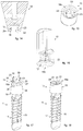
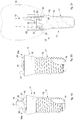
- a dental prosthetic device 10 for dental use which comprises an osseo-integratable implant 11, an accessory body 12 and connection means 13 to connect the implant 11 to the accessory body 12.
- accessory body 12 we mean, for example, an abutment, a cap, a prosthetic transferor or other prosthetic components intended to restore the masticatory, aesthetic and phonetic function and the gnathological coordination of a patient, or to allow the association of an abutment and therefore of a dental prosthesis 14 to the implant 11.
- the dental prosthetic device 10 in its entirety, or some of its components, can be made of biocompatible metal material, for example titanium.
- the implant 11 can be made of a material that has undergone a sanding treatment and/or another treatment to obtain an etched surface.
- the implant 11 comprises an oblong stem 15 which extends in a linear direction.
- the implant 11 is provided with a first end 16a and a second end, opposite the first end 16a.
- the stem 15 can have various shapes such as cylindrical, conical or blade shape, that is to say flat, tapered, or with a polygonal cross section, circular, or with possible protruding portions.
- the accessory body 12 is also provided with a first end 16b and a second end, opposite its first end 16b.
- the accessory body 12 can have a truncated cone, conical or other solid shape.
- the implant 11 can comprise a threaded portion 17 able to insert and keep permanently associated part of the implant 11 itself into the bone site of a patient.
- the stem 15 can have a truncated cone shape, at least in the terminal part of the threaded portion 17. This facilitates insertion of the threaded portion 17 into the bone site.
- the threaded portion 17 can be self-tapping, that is, such as to make a threading in the bone site when it is inserted.
- the threaded portion 17 can extend along part of the extension of the stem 15, as shown in the attached drawings, or as far as an end 16 of the stem 15 itself.
- the threaded portion 17 can have in its most extreme part one or more vertical or inclined cuts able to define a block portion 18 ( figs. 3 and 4 ).
- the implant 11 When the block portion 18 is inserted into the bone site and is osseo-integrated therein, the implant 11 has greater stability, since the block portion 18 impedes the rotation of the implant 11 in the bone site.
- the implant 11 can comprise a smooth portion 19 having a flared shape that extends from the threaded portion 17 toward the end 16a of the implant 11 in a divergent manner.
- connection means 13 are provided in the implant 11 and in the accessory body 12.
- connection means 13 comprise an attachment portion 20 intended to be received in a respective aperture 22.
- One of either the attachment portion 20 or the aperture 22 is made in the implant 11, while the other is made in the accessory body 12.
- the attachment portion 20 protrudes from the end 16a of the implant 11 and the aperture 22 is made at the end 16b of the accessory body 12.
- the attachment portion 20 is made in the end 16b of the accessory body 12 while the aperture 22 is made in the end 16a of the implant 11.
- the attachment portion 20 and the aperture 22 are configured to couple in a bayonet-shaped coupling.
- the attachment portion 20 is provided with fins 21 protruding radially from the attachment portion 20 itself, and the aperture 22 is provided with housing seatings 23 which extend radially in the aperture 22.
- the fins 21 and the housing seatings 23 have a mating shape so as to guarantee a solid and effective connection between the implant 11 and the accessory body 12.
- the number of housing seatings 23 is the same as the number of fins 21.
- the attachment portion 20, or alternatively the aperture 22, are made on the end 16a of the implant 11 opposite the one where the threaded portion 17 ends.
- the end 16a can be put in correspondence with the smooth portion 19, or in correspondence with the bigger base of the flare of the smooth portion 19.
- the smooth portion 19 can have a variable length in relation to the mucosal tract of the patient, so as to guarantee an effective aesthetic and functional solution.
- the attachment portion 20 can have a cylindrical shape emerging from the central part of the end 16a, 16b of the implant 11 or of the accessory body 12 in which it is made.
- the attachment portion 20 also has a head portion 24 from which the fins 21 protrude laterally.
- the latter can extend along the perimeter of the head portion 24 for a specific opening angle for each of the fins 21.
- the fins 21 in relation to the opening angle each define a sector of a cylindrical crown.
- each of the housing seatings 23 extends in the perimeter of the aperture 22 for an opening angle equal to a corresponding opening angle of one of the fins 21.
- the fins 21 can be disposed angularly equidistant. For example, they can be located symmetrically with respect to orthogonal planes. This allows to balance the stresses, or to discharge the stresses acting on the connection means 13.
- fins 21 are provided, they can be disposed at 180° from each other. If three fins 21 are provided, they can be disposed at 120° from each other.
- the fins 21 that protrude from the head portion 24 can lie on a common lying plane.
- the housing seatings 23 are made in the aperture 22 and can also lie on a common lying plane.
- At least one of the fins 21 and one of the housing seatings 23 extends with an opening angle greater than at least another one of the fins 21 and the housing seatings 23, respectively.
- This configuration defines a univocal positioning of the fins 21 in the respective housing seatings 23.
- the fins 21 can have a plane inclined on the surface 25 farthest from the end 16a from which the attachment portion 20 protrudes, said inclined plane being configured to generate a frictional connection in contact with the innermost wall, for example the bottom wall of the aperture 22.
- the attachment portion 20 can comprise an abutment portion 26 located between one of the fins 21 and the end 16 from which the attachment portion 20 protrudes, configured to define in cooperation with an abutment wall located in the aperture 22 the end-of-travel position between the implant 11 and the accessory body 12.
- the abutment portion 26 can comprise a tongue and can be located between the surface of the end 16a, 16b from which the attachment portion 20 and the widest surface of the fin 21 protrude.
- the abutment wall can comprise a tongue mating with the abutment portion 26 located between the innermost surface of the aperture 22 and the widest housing seating 23, or it can correspond with one of the walls of the widest housing seating 23.
- the abutment portion 26 is able to determine the end-of-travel between the implant 11 and the accessory body 12 once the attachment portion 20 has been inserted and rotated in the aperture 22.
- the fins 21, of which at least one has an opening angle wider than the others, and the abutment portion 26 generate conditions for a guided positioning of the implant 11 with respect to the accessory body 12 which prevents possible errors in positioning and connection.
- the attachment portion 20 is provided with a support base 27 located on the end 16a, 16b from which the attachment portion 20 protrudes.
- the fins 21 are positioned above the support base 27.
- the support base 27 has a flared conformation with a conicity which narrows toward the end 16a or 16b.
- the aperture 22 that receives the attachment portion 20 is made in a base surface 31 having a concave conformation, with a shape mating with the support base 27.
- the base surface 31 is positioned to completely support and cover the support base 27.
- the support base 27 is positioned in close contact with the base surface 31, and the connection means 13 are configured to ensure their reciprocal contact.
- the support base 27 is also provided with a perimeter edge 28, while the base surface 31 is provided with a clamping portion 29, or clamping edge, located, during use, around the perimeter edge 28.
- the clamping portion 29, or clamping edge can extend axially in a direction parallel to the direction of opening of the aperture 22, that is, the clamping portion 29 can be defined by a circular ridge protruding from the base surface 31. Furthermore, the clamping portion 29 overlaps and completely surrounds the perimeter edge 28.
- the clamping portion 29 and the perimeter edge 28 extend substantially in continuity with respect to each other, that is, the interface zone between the clamping portion 29 and the perimeter edge 28 is free of steps, shoulders, or cavities in which any liquids can stagnate and infiltrate toward the aperture 22.
- This seal is further completed at the time when the dental prosthesis 14 is positioned, which according to some embodiments, shown for example in fig. 2 , encloses both the clamping portion 29 and the perimeter edge 28 inside.
- the end 16a of the implant 11 from which the attachment portion 20 protrudes, or in which the aperture 22 is made is provided with at least one surface groove 30 which extends transversely with respect to the oblong development of the implant 11 and is configured to accommodate the edge of the base of a dental prosthesis 14.
- the groove 30 is defined by a rectilinear incision made in the end 16a of the implant 11 and that when it is in use, it defines with the dental prosthesis 14 a same-shape coupling which prevents reciprocal disconnection of the accessory body 12 from the implant 11.
- the material of which the dental prosthesis 14 is defined is put to fill the groove 30. This filling of the groove 30 defines a constraint against the rotation of the accessory body 12 with respect to the implant 11.
- the prosthetic device 10 can comprise an annular element 32 which can be coupled with the implant 11 and the accessory body 12 and can be positioned to surround peripherally the interface zone between the support base 27 and the base surface 31.
- the annular element 32 can be suitably shaped to be inserted into the at least one groove 30 provided in the end 16a of the implant 11.
- the annular element 32 can be coupled with a support element 33 which surrounds the annular element 32 externally and allows it to be handled.
- the support element 33 can have a tubular conformation to allow the accessory body 12 to be inserted through it.
- the support element 33 can be made of a disposable material, for example during the manufacturing step of the dental prosthesis 14.
- the disposable material melts during the manufacturing operations of the dental prosthesis 14.
- the annular element 32 with the respective support element 33, can be used during the operations to make the cast of a tooth, and the particular conformation of the annular element 32 ensures that also the dental prosthesis 14 obtained from making the cast is correctly oriented with respect to the prosthetic device 10 with which it will be coupled.
- connection means 13 allow to simulate a "one-piece" dental prosthetic device even though it is a two-phase prosthetic device.
- connection screw passing through the implant 11 and the accessory body 12, or an attachment conical pair, or both, to stabilize the connection between them.
- the surgical insertion is similar to the procedure for a "one piece", since it can be inserted through the mucosa without proceeding with the detachment of a mucous flap.
- the configuration of the implant 11 allows the operator to define the most favorable moment to stop the endosseous insertion of the implant 11 itself, and hence to guarantee the maximum aesthetic and functional result.
- the mucosal space created by the removal of the operculum can be occupied by an accessory body 12 such as a covering cap (shown in fig. 15 ), which surrounds the emerging part of the implant 11 and which is connected to the latter by connection means 13.
- an accessory body 12 such as a covering cap (shown in fig. 15 ), which surrounds the emerging part of the implant 11 and which is connected to the latter by connection means 13.
- the cap can also act as a healing cap that does not require any crimping of the soft tissues, because they are already ready to accommodate the abutment 12 and the dental prosthesis 14, ensuring maximum functional and aesthetic safety.
- the present invention can be defined as minimally invasive surgically.
- the surgical phase is one-time, possibly without removal of the mucous flap or with minimal removal thereof.
- the operator positions the emerging part of the implant 11 in the most suitable position to guarantee a satisfactory prosthetic solution from an aesthetic and functional point of view.
- the implant 11 Since it is not hollow, the implant 11 does not require embedding, but it is sufficient to apply a covering cap 12 to surround the connection means 13. This promotes the healing of the tissues intended to receive the abutment 12 and the dental prosthesis 14.
- the prosthetic phase is carried out, which requires two accessory bodies 12, that is, an implant analog and a prosthetic transferor or position abutment.
- the implant analog is similar to the implant 11, except in the part of the threaded portion 17 suitably shaped to be inserted into a plaster model.
- the prosthetic transferor or position abutment is similar to the definitive abutment, except in the part of the body 31 which is cylindrical with a vertical cut in the head which determines a hemi-section of the body 31 itself.
- This shaping of the position abutment allows to reposition it in the impression once it has been removed from the implant 11 in the mouth.
- the abutment is connected to the implant analog in the laboratory and is subsequently processed by the laboratory technician to shape the abutments and to structure the dental prosthesis 14.
- connection means 13 connecting the implant 11 to the accessory body 12, since thanks to it errors of transfer or positioning cannot possibly occur.
- connection means 13 guide the operator during the assembly step of the implant 11 to the accessory body 12, without causing uncertainty or position changes.
- connection means 13 represent a simplification both of the surgical step and of the prosthetic step.
- the risks of de-coupling and possible complications are substantially eliminated, such as the unscrewing or - worse - the breaking of the connection screw typically present in known dental prosthetic devices.
- connection means 13 guarantee a mechanical seal between the implant 11 and the accessory body 12 as in conical pair implants, but are less complex and articulated.
- the present invention also concerns an osseo-integrable implant 11 provided at one end 16 with connection means 13 to connect the latter to the accessory body 12.
- the present invention also concerns an accessory body 12 such as an abutment, a cap, a prosthetic transferor or other similar or comparable accessory body, provided at one end 16 with connection means 13 to connect the latter to an osseo-integratable implant 11.
- an accessory body 12 such as an abutment, a cap, a prosthetic transferor or other similar or comparable accessory body, provided at one end 16 with connection means 13 to connect the latter to an osseo-integratable implant 11.
- the present invention also concerns a method to connect an osseo-integratable implant 11 to an accessory body 12 such as an abutment, a cap, a prosthetic transferor or other similar or comparable accessory body, which provides to insert the attachment portion 20 protruding from one end 16 of the implant 11 or of the accessory body 12 provided with fins 21 protruding radially from the attachment portion 20 itself into the aperture 22 made in one end 16 of the other of either the accessory body 12 or the implant 11, provided with housing seatings 23 made radially in the aperture 22, and to rotate the attachment portion 20 in the aperture 22 until each of the fins 21 is housed in the respective housing seatings 23.
- an accessory body 12 such as an abutment, a cap, a prosthetic transferor or other similar or comparable accessory body
- connection method is much simpler and less articulated than in the state of the art, since it provides two installation steps which obtain a univocal positioning and connection of the implant 11 and the accessory body 12.
Landscapes
- Health & Medical Sciences (AREA)
- Oral & Maxillofacial Surgery (AREA)
- Orthopedic Medicine & Surgery (AREA)
- Dentistry (AREA)
- Epidemiology (AREA)
- Life Sciences & Earth Sciences (AREA)
- Animal Behavior & Ethology (AREA)
- General Health & Medical Sciences (AREA)
- Public Health (AREA)
- Veterinary Medicine (AREA)
- Dental Prosthetics (AREA)
Applications Claiming Priority (1)
| Application Number | Priority Date | Filing Date | Title |
|---|---|---|---|
| IT102017000070869A IT201700070869A1 (it) | 2017-06-26 | 2017-06-26 | Dispositivo protesico dentale |
Publications (1)
| Publication Number | Publication Date |
|---|---|
| EP3421005A1 true EP3421005A1 (de) | 2019-01-02 |
Family
ID=60182987
Family Applications (1)
| Application Number | Title | Priority Date | Filing Date |
|---|---|---|---|
| EP18179879.4A Withdrawn EP3421005A1 (de) | 2017-06-26 | 2018-06-26 | Zahnimplatantvorrichtung |
Country Status (2)
| Country | Link |
|---|---|
| EP (1) | EP3421005A1 (de) |
| IT (1) | IT201700070869A1 (de) |
Citations (6)
| Publication number | Priority date | Publication date | Assignee | Title |
|---|---|---|---|---|
| US20050250072A1 (en) | 2003-08-05 | 2005-11-10 | Thomas Laux | Implant part for a dental implant |
| US20120178049A1 (en) | 2010-10-20 | 2012-07-12 | Astra Tech Ab | Dental component, a dental fixture, a dental implant assembly and a dental implant system |
| US20130309630A1 (en) * | 2011-01-25 | 2013-11-21 | Dentalpoint Ag | Denture system |
| US20140205970A1 (en) * | 2011-06-01 | 2014-07-24 | Straumann Holding, AG | Two-part dental component |
| US20140272788A1 (en) | 2013-03-14 | 2014-09-18 | Biomet 3I, Llc | Twist lock interface for abutment and implant assembly |
| WO2015093673A1 (ko) | 2013-12-19 | 2015-06-25 | 김형우 | 치과용 임플란트 |
-
2017
- 2017-06-26 IT IT102017000070869A patent/IT201700070869A1/it unknown
-
2018
- 2018-06-26 EP EP18179879.4A patent/EP3421005A1/de not_active Withdrawn
Patent Citations (6)
| Publication number | Priority date | Publication date | Assignee | Title |
|---|---|---|---|---|
| US20050250072A1 (en) | 2003-08-05 | 2005-11-10 | Thomas Laux | Implant part for a dental implant |
| US20120178049A1 (en) | 2010-10-20 | 2012-07-12 | Astra Tech Ab | Dental component, a dental fixture, a dental implant assembly and a dental implant system |
| US20130309630A1 (en) * | 2011-01-25 | 2013-11-21 | Dentalpoint Ag | Denture system |
| US20140205970A1 (en) * | 2011-06-01 | 2014-07-24 | Straumann Holding, AG | Two-part dental component |
| US20140272788A1 (en) | 2013-03-14 | 2014-09-18 | Biomet 3I, Llc | Twist lock interface for abutment and implant assembly |
| WO2015093673A1 (ko) | 2013-12-19 | 2015-06-25 | 김형우 | 치과용 임플란트 |
Also Published As
| Publication number | Publication date |
|---|---|
| IT201700070869A1 (it) | 2018-12-26 |
Similar Documents
| Publication | Publication Date | Title |
|---|---|---|
| EP1624826B1 (de) | Kondensierendes skelettimplantat mit erleichterter einführung | |
| ES2937289T3 (es) | Aditamento para implante dental, pieza de poste para implante dental e implante dental | |
| RU2658158C2 (ru) | Фиксирующий узел крепления для зубного протеза | |
| US20180280121A1 (en) | Dental implant systems and methods of implantation | |
| WO2003073955A1 (en) | A fixture for orthodontic anchorage and osseo distraction of the alveolar process, and for the stabilization of temporary prostheses | |
| KR20180011103A (ko) | 골내 단일 치아 임플란트를 위한 삽입 키트 | |
| JP6639286B2 (ja) | 貫通固定される多数の義歯 | |
| US20210220095A1 (en) | Gingiva former, bite support and dental healing system | |
| EP3421005A1 (de) | Zahnimplatantvorrichtung | |
| EP2291139B1 (de) | Zahnimplantat | |
| US10869739B2 (en) | Dental implant | |
| KR200392276Y1 (ko) | 치과용 임플란트 | |
| AU2011203341B2 (en) | Condensing Skeletal Implant that Facilitate Insertions | |
| KR101292417B1 (ko) | 임플란트 시술용 토오크 렌치 | |
| KR20160073749A (ko) | 지대주에 형성된 수직절개부에 곡면절개부를 형성한 치과용 임플란트 | |
| KR200493322Y1 (ko) | 치과용 임플란트 | |
| AU2012200657B2 (en) | Condensing Skeletal Implant that Facilitate Insertions | |
| BR102021010680A2 (pt) | Implantodontia com componentes esféricos |
Legal Events
| Date | Code | Title | Description |
|---|---|---|---|
| PUAI | Public reference made under article 153(3) epc to a published international application that has entered the european phase |
Free format text: ORIGINAL CODE: 0009012 |
|
| AK | Designated contracting states |
Kind code of ref document: A1 Designated state(s): AL AT BE BG CH CY CZ DE DK EE ES FI FR GB GR HR HU IE IS IT LI LT LU LV MC MK MT NL NO PL PT RO RS SE SI SK SM TR |
|
| AX | Request for extension of the european patent |
Extension state: BA ME |
|
| STAA | Information on the status of an ep patent application or granted ep patent |
Free format text: STATUS: THE APPLICATION IS DEEMED TO BE WITHDRAWN |
|
| 18D | Application deemed to be withdrawn |
Effective date: 20190703 |