EP3421016B1 - Orthèse de main dynamique - Google Patents
Orthèse de main dynamique Download PDFInfo
- Publication number
- EP3421016B1 EP3421016B1 EP18172801.5A EP18172801A EP3421016B1 EP 3421016 B1 EP3421016 B1 EP 3421016B1 EP 18172801 A EP18172801 A EP 18172801A EP 3421016 B1 EP3421016 B1 EP 3421016B1
- Authority
- EP
- European Patent Office
- Prior art keywords
- hand
- back support
- support plate
- chain
- chain links
- Prior art date
- Legal status (The legal status is an assumption and is not a legal conclusion. Google has not performed a legal analysis and makes no representation as to the accuracy of the status listed.)
- Active
Links
Images

Classifications
-
- A—HUMAN NECESSITIES
- A61—MEDICAL OR VETERINARY SCIENCE; HYGIENE
- A61F—FILTERS IMPLANTABLE INTO BLOOD VESSELS; PROSTHESES; DEVICES PROVIDING PATENCY TO, OR PREVENTING COLLAPSING OF, TUBULAR STRUCTURES OF THE BODY, e.g. STENTS; ORTHOPAEDIC, NURSING OR CONTRACEPTIVE DEVICES; FOMENTATION; TREATMENT OR PROTECTION OF EYES OR EARS; BANDAGES, DRESSINGS OR ABSORBENT PADS; FIRST-AID KITS
- A61F5/00—Orthopaedic methods or devices for non-surgical treatment of bones or joints; Nursing devices ; Anti-rape devices
- A61F5/01—Orthopaedic devices, e.g. long-term immobilising or pressure directing devices for treating broken or deformed bones such as splints, casts or braces
- A61F5/0102—Orthopaedic devices, e.g. long-term immobilising or pressure directing devices for treating broken or deformed bones such as splints, casts or braces specially adapted for correcting deformities of the limbs or for supporting them; Ortheses, e.g. with articulations
- A61F5/013—Orthopaedic devices, e.g. long-term immobilising or pressure directing devices for treating broken or deformed bones such as splints, casts or braces specially adapted for correcting deformities of the limbs or for supporting them; Ortheses, e.g. with articulations for the arms, hands or fingers
-
- A—HUMAN NECESSITIES
- A61—MEDICAL OR VETERINARY SCIENCE; HYGIENE
- A61F—FILTERS IMPLANTABLE INTO BLOOD VESSELS; PROSTHESES; DEVICES PROVIDING PATENCY TO, OR PREVENTING COLLAPSING OF, TUBULAR STRUCTURES OF THE BODY, e.g. STENTS; ORTHOPAEDIC, NURSING OR CONTRACEPTIVE DEVICES; FOMENTATION; TREATMENT OR PROTECTION OF EYES OR EARS; BANDAGES, DRESSINGS OR ABSORBENT PADS; FIRST-AID KITS
- A61F5/00—Orthopaedic methods or devices for non-surgical treatment of bones or joints; Nursing devices ; Anti-rape devices
- A61F5/01—Orthopaedic devices, e.g. long-term immobilising or pressure directing devices for treating broken or deformed bones such as splints, casts or braces
- A61F5/0102—Orthopaedic devices, e.g. long-term immobilising or pressure directing devices for treating broken or deformed bones such as splints, casts or braces specially adapted for correcting deformities of the limbs or for supporting them; Ortheses, e.g. with articulations
- A61F2005/0132—Additional features of the articulation
- A61F2005/0144—Multibar
Definitions
- the invention relates to a dynamic hand orthosis according to the preamble of claim 1.
- Dynamic hand orthoses of this type are used for contractures or muscle weakness of the hand as well as for functional impairments of the hand, especially fingers, which are due to central events such as traumatic brain injury or stroke. Such hand orthoses can also be used postoperatively and for training finger mobility and finger strength as well as for cut injuries, tendon sutures or Dupuytren's disease.
- a hand orthosis according to the preamble of claim 1 is known from WO 2006/063347 A2 known.
- elastic spring splints or drawstrings are used, which are guided along the fingers on a glove and pull the fingers in their extension direction.
- the spring rails or drawstrings are attached at its proximal end to a holding slide which is displaceable on a back of the hand and thereby enables the length compensation required when bending the fingers.
- the back of the hand plate is held by a cuff-like forearm holding section that can be attached to the forearm in the area of the wrist.
- the invention is therefore based on the object of creating a dynamic hand orthosis of the type mentioned at the beginning, with which the bending and stretching exercises of the fingers can be carried out in a particularly ergonomic, precise and pleasant manner.
- the invention creates a hand orthosis that is particularly advantageous from an ergonomic point of view.
- the individual chain links each form a link chain for one or more fingers, the individual chain links of which can be pivoted against one another about defined pivot axes.
- the pivot axes of all chain links of a link chain are expediently aligned parallel to one another. Since the individual chain links consist of a rigid material, in particular of plastic or metal, the link chain also has a stiffness in the lateral direction, which prevents the link chain from evading in the lateral direction. Wrinkling when bending and stretching the fingers is reliably prevented.
- the finger cap holder according to the invention that is to say the link chain, also lies only on one side, in particular on the dorsal side, of the finger and it is not necessary to enclose the finger in question like a glove. On the side of the finger assigned to the palm, there can therefore be no material compressions when the finger is bent. It is also particularly advantageous that the individual chain links can be designed in such a way that they can be exchanged in a simple manner. As a result, it is also possible in a particularly simple manner to lengthen or shorten the link chain by adding or removing individual chain links and thereby adapting it to different finger and hand lengths.
- the chain links advantageously have a swivel stop in the extension and / or flexion direction.
- the extension swivel stops can in particular be designed in such a way that the link chain in its maximum extension position is arranged in a straight line in a plane that is parallel to the main plane of the back of the hand plate or is arranged therein.
- the link chain is thus given a defined starting position by means of the drawstring, which significantly facilitates the application of the hand orthosis.
- the chain links advantageously have a housing with housing walls that enclose a continuous channel. This makes it possible to guide the tension band both on the chain links and within the channel. This allows a very exact, however, tight guidance of the tension band on the chain links can be achieved at the same time.
- the chain links each have the same hinge pins and pin receiving openings for receiving the hinge pins of an adjacent chain link. This makes it possible to remove or add individual chain links in a particularly simple manner. It is particularly advantageous here if the individual chain links can be attached to one another and detached from one another without tools, which is made possible in particular by a clip or snap connection between the individual chain links.
- the link chain comprises a chain section with at least two chain links arranged between the distal end of the back of the hand support plate and the finger cap.
- at least one chain link advantageously two to five chain links, is / are assigned to each finger link.
- the link chain has only one link per finger link, the pivot axes between the chain links are expediently positioned according to the position of the finger joints.
- the chain section in question thus detects at least two chain links, while for the index, middle, ring and little fingers, the chain section in question in each case comprises at least three chain links, but advantageously 6 to 15 chain links.
- the chain section can adapt particularly well to the curvature of the associated finger.
- the finger cap holder is guided in a longitudinally displaceable manner in a longitudinal slot of the back of the hand support plate by means of a sliding block which engages under the back of the hand support plate.
- This sliding block can expediently have a T-shaped cross section, the central web engaging in the longitudinal slot and thus causing the longitudinal guidance of the sliding block and the chain strand attached to it on the back of the hand support plate.
- the elastic drawstring lies in the area between the distal end of the back of the hand support plate and the finger cap on the top of the chain links and runs in the area of the back of the hand support plate at least predominantly within the channel formed by the chain links.
- the drawstring is brought close to the back of the hand support plate and can be fastened there by means of a fastening device which projects only relatively little dorsally over the back of the hand support plate.
- the drawstring is optimally protected within the channel and receives perfect lateral guidance.
- the tension band to run along the entire chain strand on the top of the chain links or within the channel formed by the chain links.
- the back of the hand support section and the forearm support section are advantageously connected by means of a holding rail such that the back of the hand support section can be pivoted about a vertical axis relative to the forearm support section and the distance between the back of the hand support section and the forearm section is changeable. Due to the pivotable fastening of the back of the hand support plate to the holding rail, the back of the hand support plate can be pivoted in the direction of the ulnar deviation or radial deviation. Once the desired swivel position has been reached, it is fixed using a suitable locking device.
- a holding and latching device is provided between the back of the hand rest and the holding rail for latching the back of the hand rest in one or more specific pivot positions relative to the forearm holding section, the holding and latching device having at least one latching disk with teeth and a further latching element which fits positively into the Interlocking toothing engages.
- the further locking element also consists of a locking disc with a toothing which is adapted to the toothing of the opposite locking disc and engages in it.
- Both locking disks preferably have fine toothing, as a result of which a correspondingly fine angular adjustment in ulnar deviation or radial deviation is possible.
- Both locking disks are expediently rotatable about a central screw. If this central screw is loosened, the back of the hand plate can be pivoted in the ulnar deviation or in the radial deviation. The position is fixed by tightening the central screw.
- a pivot connection device between the holding rail and the back of the hand rest which has a stepless and / or a spring-loaded dynamic pivoting of the back of the hand section relative to the support rail and the forearm support section.
- the elastic drawstring is advantageously clamped on the back of the hand plate or on the forearm holding section by means of a releasable clamping device.
- a releasable clamping device By loosening this clamping device, the tension band can be moved relative to the clamping device, whereby the tensile force of the tension band can be adjusted.
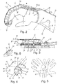
- Figure 1 shows an embodiment of a dynamic hand orthosis 1, which applies a tensile force in the extension direction, that is, in the direction of extension of the fingers, to two fingers.
- these two fingers are the middle and ring fingers when the hand orthosis 1 is placed on the right hand.
- the hand orthosis 1 has a forearm holding section 2 designed for attachment to a forearm and a backrest section 3 connected to the forearm holding section 2. From the back of the hand rest section 3, two finger cap holders 4 extend in the distal direction beyond the back of the hand rest section 3, each finger cap holder 4 consisting of a link chain 5 with a plurality of chain links 6 which are connected to one another in an articulated manner. At the distal end of each link chain 5, a finger cap 7 is attached, which is designed to insert the foremost phalange.
- the back of the hand rest section 3 and the link chains 5 are designed such that they can be placed on the back of the hand or on the relevant finger from above, as shown in FIG Figure 2 evident.
- the embodiment of the hand orthosis 1 'of Figure 2 differs from that of Figure 1 only in that a different number of chain links 6 is provided and that in Figure 2 illustrated embodiment cooperates with the index finger of the right hand. Furthermore however, the structure and operation is identical to that in Figure 1 illustrated embodiment. The following detailed description therefore applies to both the in Figure 1 as well as the in Figure 2 illustrated embodiment.
- the back of the hand support section 3 comprises a back of the hand support plate 8 which is designed to rest on the back of the hand and which extends over most of the metacarpus.
- the back of the hand support plate 8 is expediently adapted to the curvature of the back of the hand.
- the back of the hand support plate 8 can be made of metal or plastic, for example.
- a padding 9 for example in the form of a foam layer, is expediently attached to the underside of the back of the hand support plate 8 and rests on the back of the hand.
- the back of the hand support plate 8 is fastened to the forearm holding section 2 by means of a holding rail 10.
- the holding rail 10 is articulated at its distal end to the back of the hand support plate 8 in such a way that it can be pivoted relative to the holding rail 10 and thus relative to the forearm holding section 2 about a vertical axis 11 both in the direction of the ulnar deviation and in the direction of the radial deviation.
- the vertical axis 11 is thus arranged perpendicular to the back of the hand support plate 8.
- the pivoting option is illustrated by the double arrow 12 and also goes out Figure 5 forth.
- FIG. 1 The connection between the holding rail 10 and the back of the hand support plate 8 takes place via a holding and Latching device 13, which in Figure 1 is only shown schematically.
- This holding and latching device 13 has a latching disk 14 fastened to the retaining rail 10 and a further latching disk fastened on the back of the hand support plate 8, which latching disk can be designed in the same way as the latching disk 14 and is arranged below it.
- the locking disk 14 and the further locking disk have toothings on their mutually facing surfaces, which interlock when the locking disk 14 and the further locking disk lie on one another.
- the locking disc 14 and the further locking disc are held together by a screw 15 which penetrates the holding rail 10 and the locking disc 14 and is screwed into the further locking disc.
- the locking disk 14 can be raised from the additional locking disk underneath so far that the two toothings disengage and the back of the hand rest section 3 can be pivoted relative to the holding rail 10 and the forearm holding section 2. If the screw 15 is then tightened, the locking disks 14 are pressed against one another, so that the toothings engage in one another and the set swivel position is locked.
- the forearm holding section 2 has a flexible shell 16 which is designed such that it predominantly, but not completely, surrounds the forearm in an area close to the wrist.
- the shell 16 essentially has a C-shaped cross-sectional shape.
- the shell 16 is lined on the inside with a padding 17, in particular made of a foam material.
- a retaining clip 18 is fastened on each side of the shell 16 for the passage of a fastening tape 19.
- the fastening strap 19 can be passed through the two retaining clips 18 and have Velcro areas in order to adjust the length of the fastening strap 19 and thus the distance between the two retaining clips 18.
- one of the holding clips 18 can be detachably fastened to the shell 16 by means of a buckle 20.
- the holding rail 10 is fastened to the forearm holding section 2 in such a way that the distance between the forearm holding section 2 and the back of the hand rest section 3 can be changed.
- the holding rail 10 has a longitudinal slot 21 in that section which rests on the shell 16.
- Two longitudinally spaced screws 22, which are screwed into the shell 16, are passed through this longitudinal slot 21.
- the screw heads of these screws 22 overlap the holding rail 10 and prevent it from being lifted off the shell 16. If the screws 22 are loosened, the shell 16 can be displaced relative to the holding rail 10. The desired position is fixed by tightening the screws 22.
- the finger cap holder 4 formed by a link chain 5 is described in more detail below.
- the number of link chains can vary depending on the fingers with which the hand orthosis 1, 1 'is intended to work and can be from one to five.
- the two link chains 5 are constructed identically and differ only in the number of chain links 6.
- the longer link chain 5 comprises 10 chain links 6 in the exemplary embodiment shown, while the shorter link chain 5 comprises nine chain links 6.
- the number of chain links 6 is widely variable.
- the individual chain links 6 are at least largely identical.
- FIG 4 shows a single chain link 6 in isolation.
- the chain link 6 expediently consists of plastic, but can also consist of metal.
- the chain link 6 has a housing with two side walls 23, which are connected to one another by a top wall 24 and a bottom wall 25.
- a housing sleeve is formed by the side walls 23, the top wall 24 and the bottom wall 25, which encloses a channel 26 which is continuous in the longitudinal direction of the chain link 6.
- the top wall 24 and the bottom wall 25 are integrally formed on the side walls 23.
- the top wall 24 and bottom wall 25 are designed as flat plate parts.
- the side walls 23 each have an end section 27 with a circularly shaped end face 28.
- This circular arc-shaped end face 28 extends in the exemplary embodiment shown about 180 ° around a transverse pivot axis 29, but can also extend over an area that is somewhat less or more than 180 °.
- the circular arc-shaped end face 28 extends in each case from the top wall 24 to the bottom wall 25.
- the diameter of the circular arc corresponds to the clear distance between the top wall 24 and the bottom wall 25, but can also be dimensioned differently.
- each side wall 23 has a circular bolt receiving opening 30, which serves as a pivot bearing between two chain links 6 which are connected to one another in an articulated manner.
- each side wall 23 has a circularly shaped end face 31 which is concave and whose radius is matched to that of the end face 28 of the end section 27.
- An extension 32 protrudes over this end face 31 in the longitudinal direction of the chain link 6 and carries an articulation pin 33 projecting laterally outwards.
- the diameter of the pivot pin 33 is matched to that of the pin receiving opening 33 such that the pivot pins 33 of an adjacent chain link 6 can engage in the pin receiving openings 30.
- Each extension 32 is laterally offset somewhat inwards relative to the adjacent outer surface of the side walls 23, such that the end sections 27 of an adjacent chain link 6 can be pushed over the extensions 32 until the hinge pins 33 engage in the pin receiving opening 33.
- Adjacent chain links 6 can thus be pivoted relative to one another about mutually parallel transverse axes which are formed by the pivot axes 29.
- the pivoting range can expediently be limited at least in the extension direction in such a way that the link chain 5 does not extend beyond the link in FIG Figure 1 linear rectilinear position shown can pivot in the direction of extension.
- this limitation of the swiveling range is brought about by swiveling stops 34, which are formed by the free ends of the extensions 32 and protrude away from the end faces 31 beyond the hinge pins 33.
- the pivot stops 34 engage in side recesses 35 of an adjacent chain link 6, which are located on the inside of the side walls 23.
- These recesses 35 are dimensioned such that the swivel stops 34 can be swiveled within the predetermined swivel range, while the swivel stop 34 strikes the swivel range limit on the upper or lower end wall of the side recesses 35.
- the swivel stop can be implemented in a variety of other ways.
- the top walls 24 can be designed such that the top walls 24 of adjacent chain links 6 abut one another when the link chain 5 is in the maximum extension position.
- the extensions 32 are expediently so elastic that when adjacent chain links 6 are plugged together they dodge inwards and through their own Can spring back elasticity to its starting position when the hinge pins 33 are in the region of the pin receiving openings 30.
- the finger cap 7 is pivotally attached to the last chain link 6 at the distal end of the link chain 5.
- the finger cap 7 is basket-shaped and designed such that the fingertip, that is to say the last phalanx, can be inserted into the finger cap 7. Due to the basket-like or cap-like design, the finger cap 7 simultaneously forms a slip stop, which prevents the finger from slipping over the finger cap 7 in the distal direction.
- the finger cap 7 suitably consists of a textile, leather or a flexible plastic material. Alternatively, it is also readily possible for the finger cap 7 to be made of a dimensionally stable material.
- the length of the finger cap 7 is dimensioned such that only the last phalanx is wholly or partially enclosed.
- the finger cap 7 is expediently pivotably connected to the last chain link 6 about a transverse pivot axis 36.
- This pivot axis 36 can be formed, for example, by a sleeve with an internal thread arranged between the side walls 23, into which screws 37 are screwed from the two outer sides through the bolt receiving openings 30 from the two outer sides.
- the link chain 5 can be in that area which protrudes beyond the back of the hand support plate 8 Side, which faces the finger, be provided with a padding 38, in particular made of a foam material.
- the link chains 5 are held and guided in a longitudinally displaceable manner on the back of the hand support plate 8.
- the back of the hand support plate 8 shows how Figure 3 can be seen, a longitudinal slot 39 which is aligned with the longitudinal axis of the associated link chain 5.
- the padding 9 has an elongated recess 40 below the longitudinal slot 39, which is, however, wider than the longitudinal slot 39.
- a slide block 41 (see also Figure 6 ) guided longitudinally.
- This slide block 41 has a T-shaped cross section and has a longitudinal web 42 which engages in the longitudinal slot 39 from the underside.
- a base 43 protrudes on both sides over the central web 42, which engages under the back of the hand support plate 8 next to the longitudinal slot 39.
- the sliding block 41 also has two through bores 44 through which the fastening screws 45 ( Figure 3 ) can be passed through. These fastening screws 45 penetrate bores in the bottom walls 25 of two chain links 6 and are screwed to a counter plate 46 which is arranged within the channel 26 and is placed on the bottom walls 25.
- the counter plate 46 is fixedly connected to the bottom walls 25 of two further chain links 6 by means of two screws 47.
- the hand orthosis 1, 1 has an elastic tension band 49 for each chain link 6.
- This tension band 49 is fixed proximally in the region of the back of the hand rest section 2 and distally at the distal end of the finger cap holder 4, that is to say on the last chain link 6.
- this fixing takes place by means of a releasable clamping device 50.
- This clamping device 50 comprises a lower clamping base 51 and an upper clamping base 52 ( Figure 3 ), which can be screwed onto the lower clamping base 51 by means of two screws 53.
- the tension band 49 is passed between the two clamping screws 53 and between the lower and upper clamping bases 51, 52.
- the upper clamping base 52 By loosening the screws 53, the upper clamping base 52 can be lifted somewhat from the lower clamping base 51, so that a length adjustment of the tension band 49 is possible. If the proximal end of the tension band 49 is in the desired position, the upper clamping base 52 is screwed on and the tension band 49 is firmly clamped in place. Alternatively, it is also possible to provide clamping devices for the drawstrings 49, which can be opened and closed without tools.
- the tension band 49 can be fastened at its distal end to the last chain link 6, for example by that it has a distal loop which wraps around the sleeve into which the screws 37 are screwed.
- the elastic tension band 49 lies in the area between the distal end of the back of the hand support plate 8 and the finger cap 7 on the top of the chain links 6, that is to say on the ceiling walls 24, and thus runs at least in the area between the distal end of the back of the hand support plate 8 and the finger cap 7 above the chain link swivel axes.
- the tension band 49 runs within the channel 26 formed by the chain links 6.
- the link chain 5 only rests on the upper side of the assigned finger 54.
- the tension band creates a tensile force between the clamping device 50 and the finger cap 7, which pulls the finger into its extension position. If the finger is bent, as in Figure 2 shown, the tension band 49 is stretched and exerts an increasing force in the opposite direction with increasing diffraction angle. By repeatedly bending and stretching the finger, functional deficits in the hand can be reduced or eliminated and the hand and forearm muscles can be trained accordingly.
- the length compensation required when bending and stretching the finger is carried out automatically Moving the fastening section of the link chain 5 relative to the back of the hand support plate 8.
Landscapes
- Health & Medical Sciences (AREA)
- Nursing (AREA)
- Orthopedic Medicine & Surgery (AREA)
- Engineering & Computer Science (AREA)
- Biomedical Technology (AREA)
- Heart & Thoracic Surgery (AREA)
- Vascular Medicine (AREA)
- Life Sciences & Earth Sciences (AREA)
- Animal Behavior & Ethology (AREA)
- General Health & Medical Sciences (AREA)
- Public Health (AREA)
- Veterinary Medicine (AREA)
- Orthopedics, Nursing, And Contraception (AREA)
Claims (10)
- Orthèse de main dynamique comportant- une portion de retenue d'avant-bras (2) réalisée pour être fixée à un avant-bras,- une portion d'appui de dos de main (3) reliée à la portion de retenue d'avant-bras (2) et comprenant une plaque d'appui de dos de main (8) réalisée pour s'appuyer sur le dos de la main,- un capuchon de doigt (7) réalisé pour recevoir le bout d'un doigt,- un support de capuchon de doigt (4) réalisé pour s'étendre depuis la plaque d'appui de dos de main (8) le long d'un doigt (54) jusqu'au capuchon de doigt (7) et présentant une extrémité distale à laquelle est disposé le capuchon de doigt (7),- une bande de traction élastique (49) fixée de manière proximale dans la zone de la portion d'appui de dos de main (3) ou de la portion de retenue d'avant-bras (2) et de manière distale à l'extrémité distale du support de capuchon de doigt (4) ou au capuchon de doigt (7),
caractérisée en ce que
le support de capuchon de doigt (4) est constitué au moins en majeure partie d'une chaîne à maillons (5) ayant une pluralité de maillons de chaîne (6) reliés entre eux de manière articulée et est monté sur la plaque d'appui de dos de main (8) en étant mobile dans sa direction longitudinale. - Orthèse de main selon la revendication 1,caractérisée en ce queles maillons de chaîne (6) présentent une butée de pivotement (34) en direction d'extension et/ou de flexion.
- Orthèse de main selon l'une des revendications précédentes,caractérisée en ce queles maillons de chaîne (6) présentent un boîtier ayant des parois de boîtier qui entourent un canal traversant (26).
- Orthèse de main selon l'une des revendications précédentes,caractérisée en ce queles maillons de chaîne (6) présentent chacun des pivots d'articulation identiques (33) et des ouvertures de réception de pivots (30) pour recevoir les pivots d'articulation (33) d'un maillon de chaîne (6) voisin.
- Orthèse de main selon l'une des revendications précédentes,caractérisée en ce quela chaîne de maillons (5) comprend une portion de chaîne ayant au moins deux maillons de chaîne (6) et disposée entre l'extrémité distale de la plaque d'appui de dos de main (8) et le capuchon de doigt (7).
- Orthèse de main selon l'une des revendications précédentes,caractérisée en ce quele support de capuchon de doigt (4) est guidé de façon mobile en translation longitudinale dans une fente allongée (39) de la plaque d'appui de dos de main (8) au moyen d'une bloc coulissant (41) engageant par le dessous la plaque d'appui de dos de main (8).
- Orthèse de main selon l'une des revendications 3 à 6,caractérisée en ce quela bande de traction élastique (49) repose sur la face supérieure des maillons de chaîne (6) dans la zone entre l'extrémité distale de la plaque d'appui de dos de main (8) et le capuchon de doigt (7) et s'étend dans la zone de la plaque d'appui de dos de main (8) au moins partiellement à l'intérieur du canal (26) formé par les maillons de chaîne (6).
- Orthèse de main selon l'une des revendications précédentes,caractérisée en ce quela portion d'appui de dos de main (3) et la portion de retenue d'avant-bras (2) sont reliées au moyen d'une attelle de retenue (10) de telle sorte que la portion d'appui de dos de main (3) est mobile en pivotement autour d'un axe vertical (11) par rapport à la portion de retenue d'avant-bras (2) et que la distance entre la portion d'appui de dos de main (3) et la portion de retenue d'avant-bras (2) est variable.
- Orthèse de main selon la revendication 8,caractérisée en ce queentre la portion d'appui de dos de main (3) et l'attelle de retenue (10), il est prévu un moyen de retenue et d'enclenchement (13) pour enclencher la portion d'appui de dos de main (3) dans une ou dans plusieurs positions de pivotement déterminées par rapport à la portion de retenue d'avant-bras (2), le moyen de retenue et d'enclenchement (13) comprenant au moins une rondelle d'enclenchement (14) ayant une denture et un autre élément d'enclenchement qui s'engage par coopération de forme dans la denture de la rondelle d'enclenchement (14).
- Orthèse de main selon l'une des revendications précédentes,caractérisée en ce quela bande de traction élastique (49) est coincée sur la plaque d'appui de dos de main (8) ou sur la portion de retenue d'avant-bras (2) à l'aide d'un moyen de coincement amovible (50).
Applications Claiming Priority (1)
| Application Number | Priority Date | Filing Date | Title |
|---|---|---|---|
| DE102017112260.5A DE102017112260A1 (de) | 2017-06-02 | 2017-06-02 | Dynamische Handorthese |
Publications (2)
| Publication Number | Publication Date |
|---|---|
| EP3421016A1 EP3421016A1 (fr) | 2019-01-02 |
| EP3421016B1 true EP3421016B1 (fr) | 2020-05-13 |
Family
ID=62528221
Family Applications (1)
| Application Number | Title | Priority Date | Filing Date |
|---|---|---|---|
| EP18172801.5A Active EP3421016B1 (fr) | 2017-06-02 | 2018-05-17 | Orthèse de main dynamique |
Country Status (2)
| Country | Link |
|---|---|
| EP (1) | EP3421016B1 (fr) |
| DE (1) | DE102017112260A1 (fr) |
Cited By (1)
| Publication number | Priority date | Publication date | Assignee | Title |
|---|---|---|---|---|
| WO2023062469A1 (fr) * | 2021-10-13 | 2023-04-20 | Neurolutions, Inc. | Système d'orthèse à ensemble effecteur interchangeable |
Families Citing this family (1)
| Publication number | Priority date | Publication date | Assignee | Title |
|---|---|---|---|---|
| DE102020135122B3 (de) | 2020-12-30 | 2022-05-19 | Julius Zorn Gmbh | Gelenkorthese mit Artikulationsbegrenzungsmittel |
Family Cites Families (11)
| Publication number | Priority date | Publication date | Assignee | Title |
|---|---|---|---|---|
| CH590664A5 (en) * | 1976-01-06 | 1977-08-15 | Biedermann Walter G Fa | Orthopaedic prosthesis for post operative training - has hinged or rigid bar linked hand and forearm clamps and correction ties |
| US5178137A (en) * | 1990-03-16 | 1993-01-12 | Motus, Inc. | Segmented dynamic splint |
| US5697892A (en) * | 1995-09-13 | 1997-12-16 | Sutter Corporation | Continuous passive motion device for the hand and a method of using the same |
| DE202004009251U1 (de) * | 2004-06-09 | 2005-07-21 | Hochmuth, Peter | Versteifungsstreifen für einen Handschuh, insbesondere Torwarthandschuh |
| EP1827326A4 (fr) | 2004-12-10 | 2010-01-06 | Saebo Inc | Ortheses dynamiques de la main |
| US7574748B2 (en) * | 2006-03-07 | 2009-08-18 | Nike, Inc. | Glove with support system |
| BR112012023602A2 (pt) * | 2010-03-23 | 2018-11-06 | Idrogenet S R L | dispositivo para reabilitação da mão |
| DE102012002785B4 (de) * | 2012-02-15 | 2017-06-01 | Festo Ag & Co. Kg | Orthese |
| EP3226824B1 (fr) * | 2014-12-04 | 2019-06-19 | Telerobot Labs S.r.l. | Dispositif d'aide pour le mouvement et/ou la rééducation d'un ou plusieurs doigts d'une main |
| US9750290B2 (en) * | 2015-09-16 | 2017-09-05 | The Regents Of The University Of California | Passive mechanical exoskeleton to reduce hand fatigue |
| DE202015008342U1 (de) * | 2015-12-02 | 2017-03-03 | Hardy Bisinger | Handorthese |
-
2017
- 2017-06-02 DE DE102017112260.5A patent/DE102017112260A1/de not_active Withdrawn
-
2018
- 2018-05-17 EP EP18172801.5A patent/EP3421016B1/fr active Active
Non-Patent Citations (1)
| Title |
|---|
| None * |
Cited By (1)
| Publication number | Priority date | Publication date | Assignee | Title |
|---|---|---|---|---|
| WO2023062469A1 (fr) * | 2021-10-13 | 2023-04-20 | Neurolutions, Inc. | Système d'orthèse à ensemble effecteur interchangeable |
Also Published As
| Publication number | Publication date |
|---|---|
| EP3421016A1 (fr) | 2019-01-02 |
| DE102017112260A1 (de) | 2018-12-06 |
Similar Documents
| Publication | Publication Date | Title |
|---|---|---|
| DE3854651T2 (de) | Gelenkverbindung für orthopädische Kniestütze. | |
| DE19719140C2 (de) | Fraktur-Orthese | |
| EP1904002A1 (fr) | Orthese de tronc | |
| DE60320182T2 (de) | Elastischer Halter für Finger oder Zehen | |
| CH702784A1 (de) | Palmare Daumen- und Daumensattelgelenk-Schiene. | |
| DE112005000570T5 (de) | Kniescheiben-Oberschenkelorthese | |
| EP1755505B1 (fr) | Orthese de poignet | |
| DE29717429U1 (de) | Bandagen-System | |
| DE19935058B4 (de) | Gelenkschienensystem mit unabhängig handhabbarer Fixierung | |
| EP3421016A1 (fr) | Orthèse de main dynamique | |
| WO2017220084A1 (fr) | Orthèse de la main | |
| DE202018103647U1 (de) | Handgelenkorthese | |
| EP4125743B1 (fr) | Orthèse de pouce | |
| DE102009029804B4 (de) | Stützeinrichtung | |
| EP3897476B1 (fr) | Orthèse de genou | |
| CH590664A5 (en) | Orthopaedic prosthesis for post operative training - has hinged or rigid bar linked hand and forearm clamps and correction ties | |
| DE4418855A1 (de) | Knieorthese | |
| DE2554496C3 (de) | Orthese | |
| DE102015012320B4 (de) | Handgelenksorthese | |
| WO2019101654A1 (fr) | Orthèse de main et système comprenant une orthèse de main | |
| EP3713525B1 (fr) | Orthese de la main et procedure pour adapter une prothese de la main | |
| DE102018115457B4 (de) | Handgelenkorthese | |
| DE2133440C2 (de) | Gelenkstützvorrichtung | |
| DE3222774A1 (de) | Trimmgeraet | |
| DE102024119589A1 (de) | Handorthese |
Legal Events
| Date | Code | Title | Description |
|---|---|---|---|
| PUAI | Public reference made under article 153(3) epc to a published international application that has entered the european phase |
Free format text: ORIGINAL CODE: 0009012 |
|
| STAA | Information on the status of an ep patent application or granted ep patent |
Free format text: STATUS: THE APPLICATION HAS BEEN PUBLISHED |
|
| AK | Designated contracting states |
Kind code of ref document: A1 Designated state(s): AL AT BE BG CH CY CZ DE DK EE ES FI FR GB GR HR HU IE IS IT LI LT LU LV MC MK MT NL NO PL PT RO RS SE SI SK SM TR |
|
| AX | Request for extension of the european patent |
Extension state: BA ME |
|
| STAA | Information on the status of an ep patent application or granted ep patent |
Free format text: STATUS: REQUEST FOR EXAMINATION WAS MADE |
|
| 17P | Request for examination filed |
Effective date: 20190619 |
|
| RBV | Designated contracting states (corrected) |
Designated state(s): AL AT BE BG CH CY CZ DE DK EE ES FI FR GB GR HR HU IE IS IT LI LT LU LV MC MK MT NL NO PL PT RO RS SE SI SK SM TR |
|
| RIC1 | Information provided on ipc code assigned before grant |
Ipc: A61F 5/01 20060101AFI20191106BHEP |
|
| GRAP | Despatch of communication of intention to grant a patent |
Free format text: ORIGINAL CODE: EPIDOSNIGR1 |
|
| STAA | Information on the status of an ep patent application or granted ep patent |
Free format text: STATUS: GRANT OF PATENT IS INTENDED |
|
| INTG | Intention to grant announced |
Effective date: 20191220 |
|
| GRAS | Grant fee paid |
Free format text: ORIGINAL CODE: EPIDOSNIGR3 |
|
| GRAA | (expected) grant |
Free format text: ORIGINAL CODE: 0009210 |
|
| STAA | Information on the status of an ep patent application or granted ep patent |
Free format text: STATUS: THE PATENT HAS BEEN GRANTED |
|
| AK | Designated contracting states |
Kind code of ref document: B1 Designated state(s): AL AT BE BG CH CY CZ DE DK EE ES FI FR GB GR HR HU IE IS IT LI LT LU LV MC MK MT NL NO PL PT RO RS SE SI SK SM TR |
|
| REG | Reference to a national code |
Ref country code: GB Ref legal event code: FG4D Free format text: NOT ENGLISH |
|
| REG | Reference to a national code |
Ref country code: CH Ref legal event code: EP |
|
| REG | Reference to a national code |
Ref country code: DE Ref legal event code: R096 Ref document number: 502018001406 Country of ref document: DE |
|
| REG | Reference to a national code |
Ref country code: AT Ref legal event code: REF Ref document number: 1269279 Country of ref document: AT Kind code of ref document: T Effective date: 20200615 |
|
| REG | Reference to a national code |
Ref country code: LT Ref legal event code: MG4D |
|
| REG | Reference to a national code |
Ref country code: NL Ref legal event code: MP Effective date: 20200513 |
|
| PG25 | Lapsed in a contracting state [announced via postgrant information from national office to epo] |
Ref country code: NO Free format text: LAPSE BECAUSE OF FAILURE TO SUBMIT A TRANSLATION OF THE DESCRIPTION OR TO PAY THE FEE WITHIN THE PRESCRIBED TIME-LIMIT Effective date: 20200813 Ref country code: GR Free format text: LAPSE BECAUSE OF FAILURE TO SUBMIT A TRANSLATION OF THE DESCRIPTION OR TO PAY THE FEE WITHIN THE PRESCRIBED TIME-LIMIT Effective date: 20200814 Ref country code: LT Free format text: LAPSE BECAUSE OF FAILURE TO SUBMIT A TRANSLATION OF THE DESCRIPTION OR TO PAY THE FEE WITHIN THE PRESCRIBED TIME-LIMIT Effective date: 20200513 Ref country code: PT Free format text: LAPSE BECAUSE OF FAILURE TO SUBMIT A TRANSLATION OF THE DESCRIPTION OR TO PAY THE FEE WITHIN THE PRESCRIBED TIME-LIMIT Effective date: 20200914 Ref country code: IS Free format text: LAPSE BECAUSE OF FAILURE TO SUBMIT A TRANSLATION OF THE DESCRIPTION OR TO PAY THE FEE WITHIN THE PRESCRIBED TIME-LIMIT Effective date: 20200913 Ref country code: SE Free format text: LAPSE BECAUSE OF FAILURE TO SUBMIT A TRANSLATION OF THE DESCRIPTION OR TO PAY THE FEE WITHIN THE PRESCRIBED TIME-LIMIT Effective date: 20200513 Ref country code: FI Free format text: LAPSE BECAUSE OF FAILURE TO SUBMIT A TRANSLATION OF THE DESCRIPTION OR TO PAY THE FEE WITHIN THE PRESCRIBED TIME-LIMIT Effective date: 20200513 |
|
| PG25 | Lapsed in a contracting state [announced via postgrant information from national office to epo] |
Ref country code: RS Free format text: LAPSE BECAUSE OF FAILURE TO SUBMIT A TRANSLATION OF THE DESCRIPTION OR TO PAY THE FEE WITHIN THE PRESCRIBED TIME-LIMIT Effective date: 20200513 Ref country code: HR Free format text: LAPSE BECAUSE OF FAILURE TO SUBMIT A TRANSLATION OF THE DESCRIPTION OR TO PAY THE FEE WITHIN THE PRESCRIBED TIME-LIMIT Effective date: 20200513 Ref country code: BG Free format text: LAPSE BECAUSE OF FAILURE TO SUBMIT A TRANSLATION OF THE DESCRIPTION OR TO PAY THE FEE WITHIN THE PRESCRIBED TIME-LIMIT Effective date: 20200813 Ref country code: LV Free format text: LAPSE BECAUSE OF FAILURE TO SUBMIT A TRANSLATION OF THE DESCRIPTION OR TO PAY THE FEE WITHIN THE PRESCRIBED TIME-LIMIT Effective date: 20200513 |
|
| PG25 | Lapsed in a contracting state [announced via postgrant information from national office to epo] |
Ref country code: AL Free format text: LAPSE BECAUSE OF FAILURE TO SUBMIT A TRANSLATION OF THE DESCRIPTION OR TO PAY THE FEE WITHIN THE PRESCRIBED TIME-LIMIT Effective date: 20200513 Ref country code: NL Free format text: LAPSE BECAUSE OF FAILURE TO SUBMIT A TRANSLATION OF THE DESCRIPTION OR TO PAY THE FEE WITHIN THE PRESCRIBED TIME-LIMIT Effective date: 20200513 |
|
| PG25 | Lapsed in a contracting state [announced via postgrant information from national office to epo] |
Ref country code: CZ Free format text: LAPSE BECAUSE OF FAILURE TO SUBMIT A TRANSLATION OF THE DESCRIPTION OR TO PAY THE FEE WITHIN THE PRESCRIBED TIME-LIMIT Effective date: 20200513 Ref country code: RO Free format text: LAPSE BECAUSE OF FAILURE TO SUBMIT A TRANSLATION OF THE DESCRIPTION OR TO PAY THE FEE WITHIN THE PRESCRIBED TIME-LIMIT Effective date: 20200513 Ref country code: ES Free format text: LAPSE BECAUSE OF FAILURE TO SUBMIT A TRANSLATION OF THE DESCRIPTION OR TO PAY THE FEE WITHIN THE PRESCRIBED TIME-LIMIT Effective date: 20200513 Ref country code: SM Free format text: LAPSE BECAUSE OF FAILURE TO SUBMIT A TRANSLATION OF THE DESCRIPTION OR TO PAY THE FEE WITHIN THE PRESCRIBED TIME-LIMIT Effective date: 20200513 Ref country code: EE Free format text: LAPSE BECAUSE OF FAILURE TO SUBMIT A TRANSLATION OF THE DESCRIPTION OR TO PAY THE FEE WITHIN THE PRESCRIBED TIME-LIMIT Effective date: 20200513 Ref country code: DK Free format text: LAPSE BECAUSE OF FAILURE TO SUBMIT A TRANSLATION OF THE DESCRIPTION OR TO PAY THE FEE WITHIN THE PRESCRIBED TIME-LIMIT Effective date: 20200513 Ref country code: IT Free format text: LAPSE BECAUSE OF FAILURE TO SUBMIT A TRANSLATION OF THE DESCRIPTION OR TO PAY THE FEE WITHIN THE PRESCRIBED TIME-LIMIT Effective date: 20200513 |
|
| REG | Reference to a national code |
Ref country code: DE Ref legal event code: R097 Ref document number: 502018001406 Country of ref document: DE |
|
| PG25 | Lapsed in a contracting state [announced via postgrant information from national office to epo] |
Ref country code: MC Free format text: LAPSE BECAUSE OF FAILURE TO SUBMIT A TRANSLATION OF THE DESCRIPTION OR TO PAY THE FEE WITHIN THE PRESCRIBED TIME-LIMIT Effective date: 20200513 Ref country code: SK Free format text: LAPSE BECAUSE OF FAILURE TO SUBMIT A TRANSLATION OF THE DESCRIPTION OR TO PAY THE FEE WITHIN THE PRESCRIBED TIME-LIMIT Effective date: 20200513 Ref country code: PL Free format text: LAPSE BECAUSE OF FAILURE TO SUBMIT A TRANSLATION OF THE DESCRIPTION OR TO PAY THE FEE WITHIN THE PRESCRIBED TIME-LIMIT Effective date: 20200513 |
|
| PLBE | No opposition filed within time limit |
Free format text: ORIGINAL CODE: 0009261 |
|
| REG | Reference to a national code |
Ref country code: BE Ref legal event code: MM Effective date: 20200531 |
|
| STAA | Information on the status of an ep patent application or granted ep patent |
Free format text: STATUS: NO OPPOSITION FILED WITHIN TIME LIMIT |
|
| PG25 | Lapsed in a contracting state [announced via postgrant information from national office to epo] |
Ref country code: LU Free format text: LAPSE BECAUSE OF NON-PAYMENT OF DUE FEES Effective date: 20200517 |
|
| 26N | No opposition filed |
Effective date: 20210216 |
|
| PG25 | Lapsed in a contracting state [announced via postgrant information from national office to epo] |
Ref country code: IE Free format text: LAPSE BECAUSE OF NON-PAYMENT OF DUE FEES Effective date: 20200517 |
|
| PG25 | Lapsed in a contracting state [announced via postgrant information from national office to epo] |
Ref country code: BE Free format text: LAPSE BECAUSE OF NON-PAYMENT OF DUE FEES Effective date: 20200531 Ref country code: SI Free format text: LAPSE BECAUSE OF FAILURE TO SUBMIT A TRANSLATION OF THE DESCRIPTION OR TO PAY THE FEE WITHIN THE PRESCRIBED TIME-LIMIT Effective date: 20200513 |
|
| REG | Reference to a national code |
Ref country code: CH Ref legal event code: PL |
|
| PG25 | Lapsed in a contracting state [announced via postgrant information from national office to epo] |
Ref country code: CH Free format text: LAPSE BECAUSE OF NON-PAYMENT OF DUE FEES Effective date: 20210531 Ref country code: LI Free format text: LAPSE BECAUSE OF NON-PAYMENT OF DUE FEES Effective date: 20210531 |
|
| PG25 | Lapsed in a contracting state [announced via postgrant information from national office to epo] |
Ref country code: TR Free format text: LAPSE BECAUSE OF FAILURE TO SUBMIT A TRANSLATION OF THE DESCRIPTION OR TO PAY THE FEE WITHIN THE PRESCRIBED TIME-LIMIT Effective date: 20200513 Ref country code: MT Free format text: LAPSE BECAUSE OF FAILURE TO SUBMIT A TRANSLATION OF THE DESCRIPTION OR TO PAY THE FEE WITHIN THE PRESCRIBED TIME-LIMIT Effective date: 20200513 Ref country code: CY Free format text: LAPSE BECAUSE OF FAILURE TO SUBMIT A TRANSLATION OF THE DESCRIPTION OR TO PAY THE FEE WITHIN THE PRESCRIBED TIME-LIMIT Effective date: 20200513 |
|
| PG25 | Lapsed in a contracting state [announced via postgrant information from national office to epo] |
Ref country code: MK Free format text: LAPSE BECAUSE OF FAILURE TO SUBMIT A TRANSLATION OF THE DESCRIPTION OR TO PAY THE FEE WITHIN THE PRESCRIBED TIME-LIMIT Effective date: 20200513 |
|
| P01 | Opt-out of the competence of the unified patent court (upc) registered |
Effective date: 20230524 |
|
| REG | Reference to a national code |
Ref country code: AT Ref legal event code: MM01 Ref document number: 1269279 Country of ref document: AT Kind code of ref document: T Effective date: 20230517 |
|
| PG25 | Lapsed in a contracting state [announced via postgrant information from national office to epo] |
Ref country code: AT Free format text: LAPSE BECAUSE OF NON-PAYMENT OF DUE FEES Effective date: 20230517 |
|
| PG25 | Lapsed in a contracting state [announced via postgrant information from national office to epo] |
Ref country code: AT Free format text: LAPSE BECAUSE OF NON-PAYMENT OF DUE FEES Effective date: 20230517 |
|
| PGFP | Annual fee paid to national office [announced via postgrant information from national office to epo] |
Ref country code: DE Payment date: 20250519 Year of fee payment: 8 |
|
| PGFP | Annual fee paid to national office [announced via postgrant information from national office to epo] |
Ref country code: GB Payment date: 20250522 Year of fee payment: 8 |
|
| PGFP | Annual fee paid to national office [announced via postgrant information from national office to epo] |
Ref country code: FR Payment date: 20250526 Year of fee payment: 8 |
|
| PGFP | Annual fee paid to national office [announced via postgrant information from national office to epo] |
Ref country code: AT Payment date: 20260410 Year of fee payment: 5 |