EP3421075A1 - Medizinische fluidverbindungsvorrichtung - Google Patents
Medizinische fluidverbindungsvorrichtung Download PDFInfo
- Publication number
- EP3421075A1 EP3421075A1 EP18176594.2A EP18176594A EP3421075A1 EP 3421075 A1 EP3421075 A1 EP 3421075A1 EP 18176594 A EP18176594 A EP 18176594A EP 3421075 A1 EP3421075 A1 EP 3421075A1
- Authority
- EP
- European Patent Office
- Prior art keywords
- fluid
- sealing body
- connection device
- wall
- fluid channel
- Prior art date
- Legal status (The legal status is an assumption and is not a legal conclusion. Google has not performed a legal analysis and makes no representation as to the accuracy of the status listed.)
- Granted
Links
Images


Classifications
-
- A—HUMAN NECESSITIES
- A61—MEDICAL OR VETERINARY SCIENCE; HYGIENE
- A61M—DEVICES FOR INTRODUCING MEDIA INTO, OR ONTO, THE BODY; DEVICES FOR TRANSDUCING BODY MEDIA OR FOR TAKING MEDIA FROM THE BODY; DEVICES FOR PRODUCING OR ENDING SLEEP OR STUPOR
- A61M39/00—Tubes, tube connectors, tube couplings, valves, access sites or the like, specially adapted for medical use
- A61M39/10—Tube connectors; Tube couplings
-
- A—HUMAN NECESSITIES
- A61—MEDICAL OR VETERINARY SCIENCE; HYGIENE
- A61M—DEVICES FOR INTRODUCING MEDIA INTO, OR ONTO, THE BODY; DEVICES FOR TRANSDUCING BODY MEDIA OR FOR TAKING MEDIA FROM THE BODY; DEVICES FOR PRODUCING OR ENDING SLEEP OR STUPOR
- A61M39/00—Tubes, tube connectors, tube couplings, valves, access sites or the like, specially adapted for medical use
- A61M39/10—Tube connectors; Tube couplings
- A61M39/1011—Locking means for securing connection; Additional tamper safeties
-
- A—HUMAN NECESSITIES
- A61—MEDICAL OR VETERINARY SCIENCE; HYGIENE
- A61M—DEVICES FOR INTRODUCING MEDIA INTO, OR ONTO, THE BODY; DEVICES FOR TRANSDUCING BODY MEDIA OR FOR TAKING MEDIA FROM THE BODY; DEVICES FOR PRODUCING OR ENDING SLEEP OR STUPOR
- A61M39/00—Tubes, tube connectors, tube couplings, valves, access sites or the like, specially adapted for medical use
- A61M39/22—Valves or arrangement of valves
- A61M39/24—Check- or non-return valves
-
- A—HUMAN NECESSITIES
- A61—MEDICAL OR VETERINARY SCIENCE; HYGIENE
- A61M—DEVICES FOR INTRODUCING MEDIA INTO, OR ONTO, THE BODY; DEVICES FOR TRANSDUCING BODY MEDIA OR FOR TAKING MEDIA FROM THE BODY; DEVICES FOR PRODUCING OR ENDING SLEEP OR STUPOR
- A61M39/00—Tubes, tube connectors, tube couplings, valves, access sites or the like, specially adapted for medical use
- A61M39/22—Valves or arrangement of valves
- A61M39/26—Valves closing automatically on disconnecting the line and opening on reconnection thereof
-
- A—HUMAN NECESSITIES
- A61—MEDICAL OR VETERINARY SCIENCE; HYGIENE
- A61M—DEVICES FOR INTRODUCING MEDIA INTO, OR ONTO, THE BODY; DEVICES FOR TRANSDUCING BODY MEDIA OR FOR TAKING MEDIA FROM THE BODY; DEVICES FOR PRODUCING OR ENDING SLEEP OR STUPOR
- A61M39/00—Tubes, tube connectors, tube couplings, valves, access sites or the like, specially adapted for medical use
- A61M39/10—Tube connectors; Tube couplings
- A61M2039/1033—Swivel nut connectors, e.g. threaded connectors, bayonet-connectors
-
- A—HUMAN NECESSITIES
- A61—MEDICAL OR VETERINARY SCIENCE; HYGIENE
- A61M—DEVICES FOR INTRODUCING MEDIA INTO, OR ONTO, THE BODY; DEVICES FOR TRANSDUCING BODY MEDIA OR FOR TAKING MEDIA FROM THE BODY; DEVICES FOR PRODUCING OR ENDING SLEEP OR STUPOR
- A61M39/00—Tubes, tube connectors, tube couplings, valves, access sites or the like, specially adapted for medical use
- A61M39/10—Tube connectors; Tube couplings
- A61M2039/1066—Tube connectors; Tube couplings having protection means, e.g. sliding sleeve to protect connector itself, shrouds to protect a needle present in the connector, protective housing, isolating sheath
-
- A—HUMAN NECESSITIES
- A61—MEDICAL OR VETERINARY SCIENCE; HYGIENE
- A61M—DEVICES FOR INTRODUCING MEDIA INTO, OR ONTO, THE BODY; DEVICES FOR TRANSDUCING BODY MEDIA OR FOR TAKING MEDIA FROM THE BODY; DEVICES FOR PRODUCING OR ENDING SLEEP OR STUPOR
- A61M39/00—Tubes, tube connectors, tube couplings, valves, access sites or the like, specially adapted for medical use
- A61M39/10—Tube connectors; Tube couplings
- A61M2039/1077—Adapters, e.g. couplings adapting a connector to one or several other connectors
-
- A—HUMAN NECESSITIES
- A61—MEDICAL OR VETERINARY SCIENCE; HYGIENE
- A61M—DEVICES FOR INTRODUCING MEDIA INTO, OR ONTO, THE BODY; DEVICES FOR TRANSDUCING BODY MEDIA OR FOR TAKING MEDIA FROM THE BODY; DEVICES FOR PRODUCING OR ENDING SLEEP OR STUPOR
- A61M39/00—Tubes, tube connectors, tube couplings, valves, access sites or the like, specially adapted for medical use
- A61M39/22—Valves or arrangement of valves
- A61M39/24—Check- or non-return valves
- A61M2039/2433—Valve comprising a resilient or deformable element, e.g. flap valve, deformable disc
-
- A—HUMAN NECESSITIES
- A61—MEDICAL OR VETERINARY SCIENCE; HYGIENE
- A61M—DEVICES FOR INTRODUCING MEDIA INTO, OR ONTO, THE BODY; DEVICES FOR TRANSDUCING BODY MEDIA OR FOR TAKING MEDIA FROM THE BODY; DEVICES FOR PRODUCING OR ENDING SLEEP OR STUPOR
- A61M39/00—Tubes, tube connectors, tube couplings, valves, access sites or the like, specially adapted for medical use
- A61M39/22—Valves or arrangement of valves
- A61M39/24—Check- or non-return valves
- A61M2039/2473—Valve comprising a non-deformable, movable element, e.g. ball-valve, valve with movable stopper or reciprocating element
-
- A—HUMAN NECESSITIES
- A61—MEDICAL OR VETERINARY SCIENCE; HYGIENE
- A61M—DEVICES FOR INTRODUCING MEDIA INTO, OR ONTO, THE BODY; DEVICES FOR TRANSDUCING BODY MEDIA OR FOR TAKING MEDIA FROM THE BODY; DEVICES FOR PRODUCING OR ENDING SLEEP OR STUPOR
- A61M2205/00—General characteristics of the apparatus
- A61M2205/02—General characteristics of the apparatus characterised by a particular materials
- A61M2205/0216—Materials providing elastic properties, e.g. for facilitating deformation and avoid breaking
Definitions
- the invention relates to a medical fluid connection device for fluid-conducting connection with a complementary connection unit, with a housing body having an inlet opening and at least one outlet opening, which are fluid-conductively connected to each other via a substantially along an axial fluid passage, and a soft elastic sealing body, the one wall of the fluid channel in a circumferential direction at least partially surrounds and is movably guided along the axial direction relative to the wall of the fluid channel, wherein the sealing body occupies a sealing position in a non-connected state of the fluid connection device and the at least one outlet port fluid-tight seals and in a connected to the complementary terminal unit state of the fluid connection device along the axial direction is elastically compressed in a compression position such that the at least one outlet opening is released is en, wherein a Luer outer cone for fluid-tight connection with a Luer inner cone of the complementary terminal unit is provided.
- the known medical fluid connection device is provided for the fluid-conducting connection of medical tube sections, for example in an infusion therapy, and has a housing body with a base body and a thread-carrying closure part.
- the housing body has an inlet opening, which is fluid-conductively connected via a fluid channel extending along an axial direction with two outlet openings arranged at the end.
- the fluid channel is tubular, wherein the outlet openings are each in the form of a radial bore extending through a wall of the fluid channel.
- the wall of the fluid channel in a circumferential direction encompassing a soft elastic, elongated sealing body is provided.
- the sealing body seals the outlet openings in a sealing position in a fluid-tight manner.
- the sealing body In a condition of the fluid communication device connected to a complementary connection unit, the sealing body is compressed along the axial direction on the wall of the fluid channel into a compression position and thus releases the outlet openings.
- the housing body has a Luer outer cone which is provided for fluid-tight reception of a Luer inner cone of the complementary connection unit.
- the Luer outer cone is formed by a corresponding conical configuration of a front end region of the wall of the fluid channel.
- the object of the invention is to provide a medical fluid connection device of the type mentioned, which has improved properties over the prior art.
- the Luer outer cone is formed by a wall portion of the soft elastic sealing body.
- the solution according to the invention achieves a functional and production-appropriate design of the fluid connection device. This is because there is no need for a conical configuration of the wall of the fluid channel for forming the Luer outer cone. In this way, a particularly smooth movability of the sealing body between the sealing and the compression position can be achieved, since an axial force and / or circumferential force effect on the sealing body that otherwise normally occurs here - caused by a conical configuration of the wall of the fluid channel - is avoided.
- the solution according to the invention allows improved tightness of the Luer connection between the fluid connection device and the complementary connection unit.
- the wall of the fluid channel may be in the form of an elongated hollow cylinder, a tube, a sleeve or the like.
- an outer wall surface of the wall of the fluid channel may be formed in the form of a substantially straight circular cylinder surface.
- the soft-elastic sealing body may have a sleeve-like or tubular basic shape.
- an inner wall surface of the sealing body may be fixed at least in sections on the outer wall surface of the fluid channel in the radial direction.
- the sealing body can be supported in a displacement between the sealing and the compression position on the wall of the fluid channel in the radial direction and guided in the axial direction slidably.
- the sealing body may have a material composition which includes an elastomer, in particular a silicone rubber.
- the sealing body is designed such that it elastically springs back into the sealing position after deformation from the sealing into the compression position and after removal of the complementary connection unit, wherein the outlet opening is automatically sealed and thus a fluid path is automatically closed by the fluid connection device.
- the directions of the axial, radial and circumferential directions used in this specification refer to a coordinate system whose axial component is oriented coaxially or parallel with a longitudinal axis of the fluid communication device.
- the sealing body has at least one passage opening, which is arranged in the compression position at least partially overlapping the at least one outlet opening, that this at least partially released and a fluid-conducting connection between the inlet opening and the passage opening is effected. Accordingly, in the compression position of the sealing body, a fluid path extended through the fluid connection device is released, so that a corresponding fluid, for example an infusion solution, can flow between the inlet opening, the outlet opening and the passage opening.
- the at least one passage opening is arranged adjacent to the Luer outer cone. This embodiment of the invention allows a particularly functionally reliable sealing of the fluid path through the fluid connection device.
- the at least one passage opening is designed in the form of a passage slot and / or the at least one outlet opening is designed in the form of an outlet slot.
- the passage slot and / or the outlet slot may be extended substantially along the axial direction.
- the passage slot can be completely circumferentially bounded along its circumferential direction by corresponding wall sections of the sealing body or be open on at least one of its end faces.
- at least two passage slots can be arranged offset from each other along the circumferential direction of the sealing body. Accordingly, at least two outlet slots can be advantageously provided.
- the at least one outlet opening extends substantially radially through the wall of the fluid channel.
- the outlet opening is in the form of a radial opening. If the outlet opening is designed in the form of an outlet slot, it is advantageous if the outlet slot extends over at least 25% of the axial length of the wall of the fluid channel.
- the sealing body has a closure portion which seals a front end-side axial opening of the fluid channel in a fluid-tight manner.
- the fluid-tight seal of the axial opening of the fluid channel is effected at least in the sealing position of the sealing body.
- the closure portion may be configured such that the axial opening is additionally sealed in a fluid-tight manner in the compression position, and to that extent in a state connected to the complementary attachment unit.
- the closure section may be arranged to cover the axial opening at the ends and, to that extent, have an effective cross section which is greater than the cross section of the axial opening of the fluid channel.
- the closure portion a Have outer diameter, which substantially corresponds to an inner diameter of the axial opening of the fluid channel, wherein the fluid-tight seal is effected by a bearing of the closure portion in the radial direction on an inner wall of the fluid channel.
- the closure portion is formed such that it is movable in a displacement of the sealing body between the sealing and the compression position along the fluid channel in the fluid channel.
- the closure portion may be in the form of a plug, a plug, a pin or the like.
- the closure portion In a displacement of the sealing body between the sealing position and the compression position, the closure portion may be slidably supported in the axial direction and fluid-tight in the radial direction on an inner wall of the fluid channel.
- the sealing body on a profile section which is positively connected with a complementary mating profile section of the housing body, that the sealing body is fixed in the circumferential direction of the housing body, in particular on the wall of the fluid channel.
- the counter profile section is formed by a corresponding profiling of the wall of the fluid channel.
- the mating profile section may be designed accordingly in the form of a guide groove, the profile section in the form of a complementary guide element or vice versa.
- the profile section has at least one sliding element, which engages in a guide slot of the mating profile section.
- the sliding element may be in the form of a sliding strip, a sliding block, a sliding block or the like.
- the guide slot may advantageously be extended substantially along the axial direction. It is also advantageous if the guide slot is introduced into the wall of the fluid channel. A particularly tolerant fair leadership of the sealing body relative to the wall of the fluid channel can be achieved if at least two mutually circumferentially staggered sliding elements and accordingly at least two circumferentially offset from each other arranged guide slots are provided.
- the fluid channel has a receiving portion, which is provided for receiving a longitudinally extendedDofortsatzes the complementary terminal unit.
- the receiving portion may comprise a wall portion of the inner wall of the fluid channel.
- the receiving extension may be in the form of a spike, a pin, a tube or the like.
- the receiving portion may comprise a front end portion of the fluid channel.
- the housing body has a threaded portion, in particular in the form of an internal thread, which is provided for connection to a counter-threaded portion, in particular in the form of an external thread, the complementary terminal unit.
- the threaded portion may be in the form of a threaded bore, which is immovable relative to the housing body, or in the form of a relative to the housing body movable union nut, a threaded sleeve or the like.
- the fluid connection device consists of the sealing body and the housing body.
- the fluid connection device may consist of only two components, namely the sealing body and the housing body.
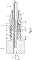
- a medical fluid connection device 1 according to the Fig. 1 . 3a to 5 is formed in the shape of a male Luer connector and provided for fluid-conducting connection of two medical tubing sections.
- the medical fluid connection device 1 is fluid-tight with a complementary connection unit 2 (FIG. Fig. 5 ), which is formed in the shape of a female Luer connector, connectable.
- the fluid connection device 1 consists of only two components, namely a housing body 3 and a soft-elastic sealing body. 4
- the housing body 3 has an inlet opening 5 arranged at the end face and at least one outlet opening 6.
- the inlet opening 5 and the outlet opening 6 are connected to one another in a fluid-conducting manner via a fluid channel 7 which extends substantially along an axial direction Y.
- the inlet opening 5 is at a front end housing extension F of the housing body 3, which is provided for fluid-tight connection with an unspecified medical hose section.
- the soft-elastic sealing body 4 is formed in its basic form in the form of a sleeve which at least partially surrounds a wall 8 of the fluid channel 7 in a circumferential direction U and is movably guided along the axial direction Y with respect to the wall 8. In other words, the sealing body 4 is attached along the axial direction Y to the wall 8 of the fluid channel 7 and so far supported in a radial direction on the wall 8.
- the sealing body 4 assumes a sealing position in a non-connected state of the fluid connection device 1. In this sealing position, the sealing body 4 seals the at least one outlet opening 6 in a fluid-tight manner, so that a fluid path extending between the inlet opening 5 and the outlet opening 6 is sealed in a fluid-tight manner.
- the sealing body 4 assumes a compression position in a state connected to the complementary connection unit 2 of the fluid connection device 1 ( Fig. 2c . 3b . 4b and 5). In this compression position, the sealing body 4 is elastically compressed along the axial direction Y such that the at least one outlet opening 6 and thus the fluid path extended through the fluid connection device 1 is released.
- a luer outer cone 9 known as such is provided for fluid-tight connection of the fluid connection device 1 with the connection unit 2.
- This Luer outer cone is provided for receiving a Luer inner cone 10 of the connection unit 2.
- the Luer outer cone 9 and the Luer inner cone 10 form so far in the field of medical technology as such known Luer connection system.
- the Luer outer cone 9 is formed by a wall section 11 of the soft-elastic sealing body 4.
- the wall portion 11 is arranged at the end face at the end of the sealing body 4 facing away from the inlet opening 5.
- the wall section 11 is a wall section of the sealing body which extends in the circumferential direction U.
- the wall section 11 comprises two partial wall sections 11a and 11b which are separated from one another in the circumferential direction U. The separation between these two partial wall sections is designed in a manner which will be explained in more detail below.
- the Luer outer cone 9 extends in the axial direction Y over about 1/9 of the total length of the sealing body 4 relative to the undeformed sealing position of the sealing body 4 (FIG. Fig. 2a ).
- the sealing body 4 has a compression portion 4a and a coupling portion 4b.
- the upset portion 4a is thin-walled in comparison to the coupling portion 4b and has due to a profiling P an accordion-like shape.
- the configuration of the upsetting section 4a permits functional elastic compressibility of the sealing body 4 along the axial direction Y.
- the coupling section 4b is comparatively thick-walled and in particular comprises the Luer outer cone 9 and the collar B. In the compression position of the sealing body 4, the coupling portion 4b is substantially undeformed, whereas the compression portion 4a is compressed to about 1/3 of its undeformed initial length.
- the sealing body 4 has two passage openings 12a, 12b. It is of course also possible that only one passage opening is provided on the sealing body 4. In the compression position of the sealing body 4, the passage opening is at least partially overlapping to the at least one outlet opening 6 arranged that this at least partially released, and thus a fluid-conducting connection between the inlet opening 5 and the two passage openings is effected.
- the passage openings 12a, 12b are each in the form of a passage slot.
- the passage slots 12a, 12b are introduced into the wall section 11 starting from an axial end face E along the axial direction Y. In that regard, the passage openings 12a, 12b subdivide the wall section 11 into the two partial wall sections 11a and 11b.
- the passage openings 12a, 12b are open in the radial direction.
- the passage openings 12a, 12b are each covered in the radial direction by a wall section 13a, 13b of the sealing body 4, in particular of the coupling section 4b.
- the at least one outlet opening 6 is designed in the form of an outlet slot.
- a second outlet opening 6a is provided, which is associated with the passage opening 12b and is likewise designed in the form of an outlet slot.
- the two outlet slots 6, 6a are - as well as the passage slots 12a, 12b - arranged offset in the circumferential direction U in approximately 180 ° to each other.
- the outlet openings 6, 6a are radially extending through the wall 8 of the fluid channel 7 and so far formed in the form of each of a radial opening.
- the length of the outlet openings 6, 6a with respect to the axial direction Y corresponds approximately to 50% of the undeformed length of the sealing body 4.
- the sealing body 4 has a closure section 14.
- the closure portion 14 is formed in the shape of a circular cylindrical plug and provided for sealing a front end axial opening 15 of the fluid channel 7.
- the closure portion 14 is formed such that it is movable in a displacement of the sealing body 4 between the sealing and the compression position along the fluid channel 7 in the fluid channel 7. In such a displacement of the sealing body 4 of the closure portion 14 is located in the radial direction on an inner wall 16 of the fluid channel 7, so that the axial opening 15 is permanently sealed.
- the sealing body 4 has two profile sections 17a, 17b. It is of course also possible that only one profile section is provided.
- the two profile sections 17a, 17b are positively connected to a respective complementary mating profile section 18a, 18b of the housing body 3. In this way, the sealing body 4 is fixed in the circumferential direction U on the housing body 3.
- the profile sections 17a, 17b are each in the form of a sliding element.
- the mating profile sections 18a, 18b are each formed in the form of a guide slot extending in the axial direction Y.
- the guide slots 18a, 18b are introduced into the wall 8, starting from the front end of the fluid channel 7 facing away from the inlet opening 5.
- the guide slots 18a, 18b extend in relation to the axial direction Y in each case over a length which corresponds to approximately 50% of the undeformed length of the sealing body 4.
- the profile sections 17a, 17b each form a material connection between the closure section 14 and the Luer outer cone 9 or the wall section 11.
- the profile sections 17a, 17b in the circumferential direction U offset by 180 ° to each other.
- the corresponding angular offset between the profile sections 17a, 17b and the passage openings 12a, 12b is in each case approximately 90 °.
- the fluid channel 7 has a receiving portion 20.
- the receiving portion 20 is provided for receiving an elongate receiving extension 21 of the complementary terminal unit 2.
- the receiving extension 21 is designed in the form of a circular cylindrical pin.
- the outer diameter of the receiving extension 21 substantially corresponds to an inner diameter of the receiving portion 20.
- the housing body 3 has a threaded portion 22.
- the threaded portion 22 is configured in the form of an internal thread.
- the internal thread 22 is provided for connection to a counter-threaded portion 23 in the form of an external thread, which is arranged at the end face, the receiving extension 21 encompassing the connection unit 2.
- the Luer inner cone 10 of the connection unit 2 is brought into contact with the Luer outer cone 9 of the fluid connection device.
- the Luer inner cone 10 is attached in the axial direction Y on the wall portion 11 of the sealing body 4 until a contact with the collar B of the coupling portion 4b is made.
- the counter-threaded portion 23 is screwed to the threaded portion 22, wherein the sealing body 4 in the axial direction starting from the sealing position ( Fig. 3a . 4a ) is compressed along the axial direction Y in the compression position.
- the receiving extension 21 enters into the receiving section 20 of the fluid channel 7 and the closure section 14 moves starting from the front end axial opening 15 of the fluid channel along the inner wall 16 in the fluid channel 7.
- the sealing body 4 by the engagement of the sliding elements 17a, 17b set in the guide slots 18a and 18b in the circumferential direction relative to the housing body 3.
- a proper connection between the fluid connection device 1 and the attachment unit 2 is established.
- the outlet slots 6, 6a are at least partially released by a corresponding positioning of the passage slots 12a and 12b.
- a fluid-conducting connection between the inlet opening 5, the outlet slots 6, 6a, the passage openings 12, 12b and a discharge channel 25 of the connection unit 2 is produced.
- a hose section which can not be seen in greater detail can be arranged, which in turn can be connected in a fluid-conducting manner with, for example, an infusion container or the like. In this way, a medical fluid can get from the inlet opening 5 to the discharge channel 25 or vice versa.
- the screw connection between the threaded portion 22 and the counter-threaded portion 23 is released manually.
- the sealing body 4 automatically takes on the elastically undeformed sealing position when removing the complementary terminal unit 2, starting from the elastically compressed sealing position. In this way, the fluid path between the inlet opening 5 and the discharge channel 25 is automatically closed.
Landscapes
- Health & Medical Sciences (AREA)
- Heart & Thoracic Surgery (AREA)
- Pulmonology (AREA)
- Engineering & Computer Science (AREA)
- Anesthesiology (AREA)
- Biomedical Technology (AREA)
- Hematology (AREA)
- Life Sciences & Earth Sciences (AREA)
- Animal Behavior & Ethology (AREA)
- General Health & Medical Sciences (AREA)
- Public Health (AREA)
- Veterinary Medicine (AREA)
- Infusion, Injection, And Reservoir Apparatuses (AREA)
Abstract
Description
- Die Erfindung betrifft eine Medizinische Fluidverbindungsvorrichtung zur fluidleitenden Verbindung mit einer komplementären Anschlusseinheit, mit einem Gehäusekörper mit einer Einlassöffnung und wenigstens einer Auslassöffnung, die über einen im Wesentlichen entlang einer Axialrichtung erstreckten Fluidkanal fluidleitend miteinander verbunden sind, und einem weichelastischen Dichtkörper, der eine Wandung des Fluidkanals in einer Umfangsrichtung wenigstens abschnittsweise umgreift und entlang der Axialrichtung gegenüber der Wandung des Fluidkanals beweglich geführt ist, wobei der Dichtkörper in einem nichtverbundenen Zustand der Fluidverbindungsvorrichtung eine Dichtposition einnimmt und die wenigstens eine Auslassöffnung fluiddicht abdichtet und in einem mit der komplementären Anschlusseinheit verbundenen Zustand der Fluidverbindungsvorrichtung entlang der Axialrichtung derart elastisch in eine Stauchposition gestaucht ist, dass die wenigstens eine Auslassöffnung freigegeben ist, wobei ein Luer-Außenkonus zur fluiddichten Verbindung mit einem Luer-Innenkonus der komplementären Anschlusseinheit vorgesehen ist.
- Eine derartige Vorrichtung ist aus der
WO 2010/028040 A1 bekannt. Die bekannte medizinische Fluidverbindungsvorrichtung ist zur fluidleitenden Verbindung medizinischer Schlauchabschnitte, beispielsweise bei einer Infusionstherapie, vorgesehen und weist einen Gehäusekörper mit einem Grundkörper und einem gewindetragenden Verschlussteil auf. Der Gehäusekörper weist eine Einlassöffnung auf, die über einen entlang einer Axialrichtung erstreckten Fluidkanal mit zwei stirnendseitig angeordneten Auslassöffnungen fluidleitend verbunden ist. Der Fluidkanal ist rohrförmig ausgebildet, wobei die Auslassöffnungen jeweils in Form einer Radialbohrung durch eine Wandung des Fluidkanals erstreckt sind. Die Wandung des Fluidkanals in einer Umfangsrichtung umgreifend ist ein weichelastischer, längserstreckter Dichtköper vorgesehen. Der Dichtkörper dichtet in einer Dichtposition die Auslassöffnungen fluiddicht ab. In einem mit einer komplementären Anschlusseinheit verbundenen Zustand der Fluidverbindungsvorrichtung ist der Dichtköper entlang der Axialrichtung auf der Wandung des Fluidkanals in eine Stauchposition gestaucht und gibt derart die Auslassöffnungen frei. Der Gehäusekörper weist einen Luer-Außenkonus auf, der zur fluiddichten Aufnahme eines Luer-Innenkonus der komplementären Anschlusseinheit vorgesehen ist. Der Luer-Außenkonus ist durch eine entsprechend konische Ausgestaltung eines stirnendseitigen Bereichs der Wandung des Fluidkanals ausgebildet. - Aufgabe der Erfindung ist es, eine medizinische Fluidverbindungsvorrichtung der eingangs genannten Art zu schaffen, die gegenüber dem Stand der Technik verbesserte Eigenschaften aufweist.
- Diese Aufgabe wird dadurch gelöst, dass der Luer-Außenkonus durch einen Wandabschnitt des weichelastischen Dichtkörpers ausgebildet ist. Durch die erfindungsgemäße Lösung wird zum einen eine funktions- und fertigungsgerechte Ausgestaltung der Fluidverbindungsvorrichtung erreicht. Dies, da auf eine konische Ausgestaltung der Wandung des Fluidkanals zur Ausbildung des Luer-Außenkonus verzichtet werden kann. Derart kann eine besonders leichtgängige Bewegbarkeit des Dichtkörpers zwischen der Dicht- und der Stauchposition erreicht werden, da eine ansonsten üblicherweise hierbei auftretende - durch eine konusförmige Ausgestaltung der Wandung des Fluidkanals bewirkte - Axialkraft- und/oder Umfangskrafteinwirkung auf den Dichtkörper vermieden wird. Zum anderen erlaubt die erfindungsgemäße Lösung eine verbesserte Dichtigkeit der Luer-Verbindung zwischen der Fluidverbindungsvorrichtung und der komplementären Anschlusseinheit. Dies, da der Luer-Außenkonus an dem weichelastischen Dichtkörper ausgebildet ist. Derart können etwaig vorhandene Form- und/oder Lagetoleranzen der Luer-Verbindung zwischen der Fluidverbindungsvorrichtung und der Anschlusseinheit mittels einer elastischen Deformation des Dichtkörpers ausgeglichen werden. Auf diese Weise kann eine Undichtigkeit vermieden werden. Die Wandung des Fluidkanals kann in Form eines längserstreckten Hohlzylinders, einer Röhre, einer Hülse oder dergleichen ausgebildet sein. Vorteilhafterweise kann eine Außenwandfläche der Wandung des Fluidkanals in Form einer im Wesentlichen geraden Kreiszylinderfläche ausgebildet sein. Der weichelastische Dichtkörper kann eine hülsen- oder röhrenartige Grundform aufweisen. Vorteilhafterweise kann eine Innenwandfläche des Dichtkörpers wenigstens abschnittsweise an der Außenwandfläche des Fluidkanals in Radialrichtung festgelegt sein. Insoweit kann der Dichtkörper bei einer Verlagerung zwischen der Dicht- und der Stauchposition auf der Wandung des Fluidkanals in Radialrichtung abgestützt und in Axialrichtung gleitend geführt sein. Der Dichtkörpers kann eine Werkstoffzusammensetzung aufweisen, die ein Elastomer, insbesondere ein Silikonkautschuk, beinhaltet. Von Vorteil ist der Dichtkörper derart ausgestaltet, dass dieser nach einer Deformation von der Dicht- in die Stauchposition - und nach Entfernen der komplementären Anschlusseinheit - elastisch in die Dichtposition zurückfedert, wobei die Auslassöffnung selbsttätig abgedichtet und somit ein Fluidpfad durch die Fluidverbindungsvorrichtung selbsttätig verschlossen wird. Die in dieser Beschreibung verwendeten Richtungsangaben der Axial-, der Radial- und der Umfangsrichtung beziehen sich auf ein Koordinatensystem, dessen Axialkomponente koaxial oder parallel mit einer Längsachse der Fluidverbindungsvorrichtung orientiert ist.
- In Ausgestaltung der Erfindung weist der Dichtkörper wenigstens eine Durchlassöffnung auf, die in der Stauchposition derart zumindest abschnittsweise überdeckend zu der wenigstens einen Auslassöffnung angeordnet ist, dass diese wenigstens abschnittsweise freigegeben und eine fluidleitende Verbindung zwischen der Einlassöffnung und der Durchlassöffnung bewirkt ist. Demzufolge ist in der Stauchposition des Dichtkörpers ein durch die Fluidverbindungsvorrichtung erstreckter Fluidpfad freigegeben, so dass ein entsprechendes Fluid, beispielsweise eine Infusionslösung, zwischen der Einlassöffnung, der Auslassöffnung und der Durchlassöffnung strömen kann. Vorteilhafterweise kann die wenigstens eine Durchlassöffnung an den Luer-Außenkonus angrenzend angeordnet ist. Diese Ausgestaltung der Erfindung erlaubt eine besonders funktionssichere Abdichtung des Fluidpfads durch die Fluidverbindungsvorrichtung.
- In weiterer Ausgestaltung der Erfindung ist die wenigstens eine Durchlassöffnung in Gestalt eines Durchlassschlitzes ausgebildet und/oder die wenigstens eine Auslassöffnung ist in Gestalt eines Auslassschlitzes ausgebildet. Von Vorteil kann der Durchlassschlitz und/oder der Auslassschlitz im Wesentlichen entlang der Axialrichtung erstreckt sein. Der Durchlassschlitz kann entlang seiner Umfangsrichtung durch entsprechende Wandabschnitte des Dichtkörpers vollständig umlaufend berandet sein oder an wenigstens einer seiner Stirnendseiten offen sein. Vorteilhafterweise können wenigstens zwei Durchlassschlitze entlang der Umfangsrichtung des Dichtkörpers zueinander versetzt angeordnet sein. Dementsprechend können von Vorteil wenigstens zwei Auslassschlitze vorgesehen sein.
- In weiterer Ausgestaltung der Erfindung ist die wenigstens eine Auslassöffnung im Wesentlichen radial durch die Wandung des Fluidkanals erstreckt. Demzufolge ist die Auslassöffnung in Form einer Radialöffnung ausgebildet. Sofern die Auslassöffnung in Gestalt eines Auslassschlitzes ausgebildet ist, ist es vorteilhaft, wenn der Auslassschlitz über wenigstens 25 % der Axiallänge der Wandung des Fluidkanals erstreckt ist.
- In weiterer Ausgestaltung der Erfindung weist der Dichtkörper einen Verschlussabschnitt auf, der eine stirnendseitige Axialöffnung des Fluidkanals fluiddicht abdichtet. Die derartige fluiddichte Abdichtung der Axialöffnung des Fluidkanals ist wenigstens in der Dichtposition des Dichtkörpers bewirkt. Vorteilhafterweise kann der Verschlussabschnitt derart ausgestaltet sein, dass die Axialöffnung zudem in der Stauchposition - und insoweit in einem mit der komplementären Anschlusseinheit verbundenen Zustand - fluiddicht abgedichtet ist. Der Verschlussabschnitt kann die Axialöffnung stirnendseitig abdeckend angeordnet sein und insoweit einen wirksamen Querschnitt aufweisen, der größer ist als der Querschnitt der Axialöffnung des Fluidkanals. Alternativ kann der Verschlussabschnitt einen Außendurchmesser aufweisen, der im Wesentlichen einem Innendurchmesser der Axialöffnung des Fluidkanals entspricht, wobei die fluiddichte Abdichtung durch eine Anlage des Verschlussabschnitts in radialer Richtung an einer Innenwandung des Fluidkanals bewirkt ist.
- In weiterer Ausgestaltung der Erfindung ist der Verschlussabschnitt derart ausgebildet, dass dieser bei einer Verlagerung des Dichtkörpers zwischen der Dicht- und der Stauchposition entlang des Fluidkanals in dem Fluidkanal beweglich ist. Der Verschlussabschnitt kann in Gestalt eines Stopfens, eines Pfropfens, eines Zapfens oder dergleichen ausgebildet sein. Bei einer Verlagerung des Dichtkörpers zwischen der Dichtposition und der Stauchposition kann der Verschlussabschnitt in Axialrichtung gleitbeweglich und in Radialrichtung fluiddicht an einer Innenwandung des Fluidkanals abgestützt sein. Diese Ausgestaltung der Erfindung gewährleistet eine besonders funktionssichere Abdichtung der Axialöffnung des Fluidkanals.
- In weiterer Ausgestaltung der Erfindung weist der Dichtkörper einen Profilabschnitt auf, der derart formschlüssig mit einem komplementären Gegenprofilabschnitt des Gehäusekörpers verbunden ist, dass der Dichtkörper in Umfangsrichtung an dem Gehäusekörper, insbesondere an der Wandung des Fluidkanals, festgelegt ist. Es ist vorteilhaft, wenn der Gegenprofilabschnitt durch eine entsprechende Profilierung der Wandung des Fluidkanals ausgebildet ist. Der Gegenprofilabschnitt kann in Gestalt einer Führungsnut, der Profilabschnitt dementsprechend in Gestalt eines komplementären Führungselements ausgebildet sein oder umgekehrt. Infolge der formschlüssigen Verbindung in Umfangsrichtung zwischen dem Profilabschnitt und dem Gegenprofilabschnitt wird einem ungewollten Verdrehen des Dichtkörpers bei einer Verlagerung zwischen der Dicht- und der Stauchposition entgegengewirkt. Diese Ausgestaltung der Erfindung erlaubt demzufolge eine besonders toleranzgerechte Führung des Dichtkörpers gegenüber der Wandung des Fluidkanals. Auf diese Weise kann ein besonders zuverlässiges Verschließen und Öffnen des durch die Fluidverbindungsvorrichtung erstreckten Fluidpfads erreicht werden.
- In weiterer Ausgestaltung der Erfindung weist der Profilabschnitt wenigstens ein Gleitelement auf, das in einen Führungsschlitz des Gegenprofilabschnitts eingreift. Das Gleitelement kann in Form einer Gleitleiste, eines Gleitschuhs, eines Gleitsteins oder dergleichen ausgebildet sein. Der Führungsschlitz kann vorteilhafterweise im Wesentlichen entlang der Axialrichtung erstreckt sein. Es ist zudem vorteilhaft, wenn der Führungsschlitz in die Wandung des Fluidkanals eingebracht ist. Eine besonders toleranzgerechte Führung des Dichtkörpers gegenüber der Wandung des Fluidkanals kann erreicht werden, wenn wenigstens zwei in Umfangsrichtung zueinander versetzt angeordnete Gleitelemente und dementsprechend wenigstens zwei in Umfangsrichtung zueinander versetzt angeordnete Führungsschlitze vorgesehen sind.
- In weiterer Ausgestaltung der Erfindung weist der Fluidkanal einen Aufnahmeabschnitt auf, der zur Aufnahme eines längserstreckten Aufnahmefortsatzes der komplementären Anschlusseinheit vorgesehen ist. Der Aufnahmeabschnitt kann einen Wandabschnitt der Innenwandung des Fluidkanals umfassen. Der Aufnahmefortsatz kann in Form eines Dorns, eines Stifts, einer Röhre oder dergleichen ausgebildet sein. Vorteilhafterweise kann der Aufnahmeabschnitt einen stirnendseitigen Abschnitt des Fluidkanals umfassen. Diese Ausgestaltung der Erfindung erlaubt eine besonders toleranzgerechte Ausrichtung der Fluidverbindungsvorrichtung und der komplementären Anschlusseinheit zueinander, so dass dementsprechend eine besonders toleranzgerechte Ausrichtung des Luer-Außenkonus gegenüber dem Luer-Innenkonus erreicht wird. Auf diese Weise können ungewollte Undichtigkeiten vermieden werden.
- In weiterer Ausgestaltung der Erfindung weist der Gehäusekörper einen Gewindeabschnitt, insbesondere in Gestalt eines Innengewindes, auf, der zur Verbindung mit einem Gegengewindeabschnitt, insbesondere in Form eines Außengewindes, der komplementären Anschlusseinheit vorgesehen ist. Der Gewindeabschnitt kann in Gestalt einer Gewindebohrung, die gegenüber dem Gehäusekörper unbeweglich ist, oder in Gestalt einer gegenüber dem Gehäusekörper beweglichen Überwurfmutter, einer Gewindehülse oder dergleichen ausgebildet sein. Durch diese Ausgestaltung der Erfindung wird einem unbeabsichtigten Lösen der Verbindung zwischen dem Luer-Außenkonus und dem Luer-Innenkonus entgegengewirkt.
- Die der Erfindung zugrunde liegende Aufgabe wird auch dadurch gelöst, dass die Fluidverbindungsvorrichtung aus dem Dichtkörper und dem Gehäusekörper besteht. Insoweit kann die Fluidverbindungsvorrichtung aus lediglich zwei Komponenten, nämlich dem Dichtkörper und dem Gehäusekörper, bestehen. Durch die derartige Reduktion der Anzahl der Bauteile kann eine besonders einfache und kostengünstige Fertigung erreicht werden.
- Weitere Vorteile und Merkmale der Erfindung ergeben sich aus den Ansprüchen sowie aus der nachfolgenden Beschreibung eines bevorzugten Ausführungsbeispiels der Erfindung, das anhand der Zeichnungen dargestellt ist.
- Fig. 1
- zeigt in schematischer Perspektivdarstellung eine Ausführungsform einer erfindungsgemäßen Fluidverbindungsvorrichtung, die insbesondere zur fluiddichten Verbindung von Schlauchabschnitten bei einer Infusionstherapie vorgesehen ist,
- Fig. 2a
- in einer schematischen Perspektivdarstellung entsprechend
Fig. 1 einen weichelastischen Dichtkörper der Fluidverbindungsvorrichtung nachFig. 1 in einem elastisch undeformierten Zustand (Dichtposition), - Fig. 2b und 2c
- den Dichtkörper nach den
Fig. 1 und2a in einer schematischen Längsschnittdarstellung in einer Schnittebene Y-Z gemäßFig. 1 in dem elastisch undeformiertem Zustand (Fig. 2b ) und in einem elastisch gestauchten Zustand (Stauchposition) (Fig. 2c ), - Fig. 3a und 3b
- in einer schematischen Längsschnittdarstellung in einer Schnittebene Y-Z gemäß
Fig. 1 die Fluidverbindungsvorrichtung nachFig. 1 in einem fluiddicht verschlossenen Zustand (Fig. 3a ) und in einem geöffneten Zustand (Fig. 3b ), wobei der Dichtkörper die Stauchposition einnimmt, - Fig. 4a und 4b
- in einer weiteren schematischen Längsschnittdarstellung in einer Schnittebene X-Y gemäß
Fig. 1 die Fluidverbindungsvorrichtung nach denFig. 1 und3a sowie 3b in fluiddicht verschlossenem Zustand (Fig. 4a ) und dem entsprechendFig. 3b geöffneten Zustand (Fig. 4b ) und - Fig. 5
- in einer schematischen Längsschnittdarstellung in einer Schnittebene X-Y gemäß
Fig. 1 die Fluidverbindungsvorrichtung nach denFig. 1 ,3a ,3b ,4a sowie 4b in einem mit einer komplementären Anschlusseinheit verbundenen Zustand. - Eine medizinische Fluidverbindungsvorrichtung 1 nach den
Fig. 1 ,3a bis 5 ist in Gestalt eines männlichen Luer-Anschlusskonnektors ausgebildet und zur fluidleitenden Verbindung zweier medizinischer Schlauchleitungsabschnitte vorgesehen. Zu diesem Zweck ist die medizinische Fluidverbindungsvorrichtung 1 auf noch näher zu erläuternde Art und Weise fluiddicht mit einer komplementären Anschlusseinheit 2 (Fig. 5 ), die in Gestalt eines weiblichen Luer-Anschlusskonnektors ausgebildet ist, verbindbar. - Die Fluidverbindungsvorrichtung 1 besteht aus lediglich zwei Bauteilen, nämlich einem Gehäusekörper 3 und einem weichelastischen Dichtkörper 4.
- Der Gehäusekörper 3 weist eine stirnendseitig angeordnete Einlassöffnung 5 und wenigstens eine Auslassöffnung 6 auf. Die Einlassöffnung 5 und die Auslassöffnung 6 sind über einen im Wesentlichen entlang einer Axialrichtung Y erstreckten Fluidkanal 7 fluidleitend miteinander verbunden. Die Einlassöffnung 5 ist an einem stirnendseitigen Gehäusefortsatz F des Gehäusekörpers 3 angeordnet, der zur fluiddichten Verbindung mit einem nicht näher bezeichneten medizinischen Schlauchabschnitt vorgesehen ist. Der weichelastische Dichtkörper 4 ist in seiner Grundform in Gestalt einer Hülse ausgebildet, die eine Wandung 8 des Fluidkanals 7 in einer Umfangsrichtung U wenigstens abschnittsweise umgreift und entlang der Axialrichtung Y gegenüber der Wandung 8 beweglich geführt ist. Mit anderen Worten: Der Dichtkörper 4 ist entlang der Axialrichtung Y auf die Wandung 8 des Fluidkanals 7 aufgesteckt und insoweit in einer radialen Richtung an der Wandung 8 abgestützt.
- Wie insbesondere anhand der
Fig. 3a und4a ersichtlich ist, nimmt der Dichtkörper 4 in einem nicht verbundenen Zustand der Fluidverbindungsvorrichtung 1 eine Dichtposition ein. In dieser Dichtposition dichtet der Dichtkörper 4 die wenigstens eine Auslassöffnung 6 fluiddicht ab, so dass ein zwischen der Einlassöffnung 5 und der Auslassöffnung 6 erstreckter Fluidpfad fluiddicht abgedichtet ist. Demgegenüber nimmt der Dichtkörper 4 in einem mit der komplementären Anschlusseinheit 2 verbundenen Zustand der Fluidverbindungsvorrichtung 1 eine Stauchposition ein (Fig. 2c ,3b ,4b sowie 5). In dieser Stauchposition ist der Dichtkörper 4 entlang der Axialrichtung Y derart elastisch gestaucht, dass die wenigstens eine Auslassöffnung 6 und somit der durch die Fluidverbindungsvorrichtung 1 erstreckte Fluidpfad freigegeben ist. - Zur fluiddichten Verbindung der Fluidverbindungsvorrichtung 1 mit der Anschlusseinheit 2 ist ein als solcher bekannter Luer-Außenkonus 9 vorgesehen. Dieser Luer-Außenkonus ist zur Aufnahme eines Luer-Innenkonus 10 der Anschlusseinheit 2 vorgesehen. Der Luer-Außenkonus 9 und der Luer-Innenkonus 10 bilden insoweit ein im Bereich der Medizintechnik als solches bekanntes Luer-Verbindungssystem aus.
- Erfindungsgemäß ist der Luer-Außenkonus 9 durch einen Wandabschnitt 11 des weichelastischen Dichtkörpers 4 ausgebildet. Wie insbesondere anhand der
Fig. 2a bis 2c ersichtlich ist, ist der Wandabschnitt 11 stirnendseitig an dem der Einlassöffnung 5 abgewandten Ende des Dichtkörpers 4 angeordnet. Der Wandabschnitt 11 ist ein in Umfangsrichtung U erstreckter Wandabschnitt des Dichtkörpers. In Axialrichtung Y ist der Wandabschnitt durch einen radial erstreckten Bund B begrenzt. Zudem umfasst der Wandabschnitt 11 zwei in Umfangsrichtung U voneinander getrennte Teilwandabschnitte 11a und 11b, wobei die Trennung zwischen diesen beiden Teilwandabschnitten auf noch näher zu erläuternde Art und Weise ausgebildet ist. Der Luer-Außenkonus 9 erstreckt sich in Axialrichtung Y über in etwa 1/9 der Gesamtlänge des Dichtkörpers 4 bezogen auf die undeformierte Dichtposition des Dichtkörpers 4 (Fig. 2a ). - Wie weiter insbesondere anhand der
Fig. 2a bis 2c ersichtlich ist, weist der Dichtkörper 4 einen Stauchabschnitt 4a sowie einen Kopplungsabschnitt 4b auf. Der Stauchabschnitt 4a ist im Vergleich zu dem Kopplungsabschnitt 4b dünnwandig ausgestaltet und weist infolge einer Profilierung P eine ziehharmonikaartige Gestalt auf. In Verbindung mit der weichelastischen Materialzusammensetzung des Dichtkörpers 4, die insbesondere Silikonkautschuk aufweisen kann, erlaubt die derartige Ausgestaltung des Stauchabschnitts 4a eine funktionsgerechte elastische Stauchbarkeit des Dichtkörpers 4 entlang der Axialrichtung Y. Demgegenüber ist der Kopplungsabschnitt 4b vergleichsweise dickwandig ausgeführt und umfasst insbesondere den Luer-Außenkonus 9 sowie dem Bund B. In der Stauchposition des Dichtkörpers 4 ist der Kopplungsabschnitt 4b im Wesentlichen undeformiert, wohingegen der Stauchabschnitt 4a auf in etwa 1/3 seiner undeformierten Ausgangslänge zusammengestaucht ist. - Weiter weist der Dichtkörper 4 zwei Durchlassöffnungen 12a, 12b auf. Es ist selbstverständlich auch möglich, dass lediglich eine Durchlassöffnung an dem Dichtkörper 4 vorgesehen ist. In der Stauchposition des Dichtkörpers 4 ist die Durchlassöffnung derart zumindest abschnittsweise überdeckend zu der wenigstens einen Auslassöffnung 6 angeordnet, dass diese wenigstens abschnittsweise freigegeben und somit eine fluidleitende Verbindung zwischen der Einlassöffnung 5 und den beiden Durchlassöffnungen bewirkt ist. Die Durchlassöffnungen 12a, 12b sind jeweils in Gestalt eines Durchlassschlitzes ausgebildet. Die Durchlassschlitze 12a, 12b sind ausgehend von einer axialen Stirnendfläche E entlang der Axialrichtung Y in den Wandabschnitt 11 eingebracht. Insoweit unterteilen die Durchlassöffnungen 12a, 12b den Wandabschnitt 11 in die beiden Teilwandabschnitte 11a und 11b. Im Bereich des Luer-Außenkonus 9 bzw. des Wandabschnitts 11 sind die Durchlassöffnungen 12a, 12b in radialer Richtung offen. In einem sich in der Axialrichtung Y an den Luer-Außenkonus 9 anschließenden Bereich sind die Durchlassöffnungen 12a, 12b in radialer Richtung jeweils durch einen Wandabschnitt 13a, 13b des Dichtkörpers 4, insbesondere des Kopplungsabschnitts 4b, abgedeckt.
- Entsprechend zu der schlitzförmigen Ausgestaltung der Durchlassöffnung 12a ist die wenigstens eine Auslassöffnung 6 in Gestalt eines Auslassschlitzes ausgebildet. Zudem ist eine zweite Auslassöffnung 6a vorgesehen, die der Durchlassöffnung 12b zugeordnet und ebenfalls in Gestalt eines Auslassschlitzes ausgebildet ist. Die beiden Auslassschlitze 6, 6a sind - ebenso wie die Durchlassschlitze 12a, 12b - in Umfangsrichtung U in etwa um 180° zueinander versetzt angeordnet. Die Auslassöffnungen 6, 6a sind radial durch die Wandung 8 des Fluidkanals 7 erstreckt und insoweit in Gestalt von jeweils einer Radialöffnung ausgebildet. Die Länge der Auslassöffnungen 6, 6a in Bezug auf die Axialrichtung Y entspricht in etwa 50 % der undeformierten Länge des Dichtkörpers 4.
- Weiter weist der Dichtkörper 4 einen Verschlussabschnitt 14 auf. Der Verschlussabschnitt 14 ist in Gestalt eines kreiszylinderförmigen Stopfens ausgebildet und zur Abdichtung einer stirnendseitigen Axialöffnung 15 des Fluidkanals 7 vorgesehen. Wie insbesondere anhand der
Fig. 3a und3b ersichtlich ist, ist der Verschlussabschnitt 14 derart ausgebildet, dass dieser bei einer Verlagerung des Dichtkörpers 4 zwischen der Dicht- und der Stauchposition entlang des Fluidkanals 7 in dem Fluidkanal 7 beweglich ist. Bei einer derartigen Verlagerung des Dichtkörpers 4 liegt der Verschlussabschnitt 14 in radialer Richtung an einer Innenwandung 16 des Fluidkanals 7 an, so dass die Axialöffnung 15 permanent abgedichtet ist. - Weiter weist der Dichtkörper 4 zwei Profilabschnitte 17a, 17b auf. Es ist selbstverständlich auch möglich, dass lediglich ein Profilabschnitt vorgesehen ist. Die beiden Profilabschnitte 17a, 17b sind formschlüssig mit jeweils einem komplementären Gegenprofilabschnitt 18a, 18b des Gehäusekörpers 3 verbunden. Auf diese Weise ist der Dichtkörper 4 in Umfangsrichtung U an dem Gehäusekörper 3 festgelegt. Die Profilabschnitte 17a, 17b sind jeweils in Gestalt eines Gleitelements ausgebildet. Dementsprechend sind die Gegenprofilabschnitte 18a, 18b jeweils in Gestalt eines in Axialrichtung Y erstreckten Führungsschlitzes ausgebildet. Die Führungsschlitze 18a, 18b sind jeweils ausgehend von dem der Einlassöffnung 5 abgewandten Stirnende des Fluidkanals 7 in dessen Wandung 8 eingebracht. Die Führungsschlitze 18a, 18b erstrecken sich in Bezug auf die Axialrichtung Y jeweils über eine Länge, die in etwa 50 % der undeformierten Länge des Dichtkörpers 4 entspricht. Im Übrigen bilden die Profilabschnitte 17a, 17b jeweils eine Materialanbindung zwischen dem Verschlussabschnitt 14 und dem Luer-Außenkonus 9 bzw. dem Wandabschnitt 11. Wie weiter insbesondere anhand
Fig. 2a ersichtlich ist, sind die Profilabschnitte 17a, 17b in Umfangsrichtung U um 180° versetzt zueinander angeordnet. Hierbei beträgt der entsprechende Winkelversatz zwischen den Profilabschnitten 17a, 17b und den Durchlassöffnungen 12a, 12b jeweils in etwa 90°. - Wie weiter insbesondere anhand
Fig. 5 ersichtlich ist, weist der Fluidkanal 7 einen Aufnahmeabschnitt 20 auf. Der Aufnahmeabschnitt 20 ist zur Aufnahme eines längserstreckten Aufnahmefortsatzes 21 der komplementären Anschlusseinheit 2 vorgesehen. Der Aufnahmefortsatz 21 ist in Gestalt eines kreiszylindrischen Stiftes ausgestaltet. Der Außendurchmesser des Aufnahmefortsatzes 21 entspricht im Wesentlichen einem Innendurchmesser des Aufnahmeabschnitts 20. - Zudem weist der Gehäusekörper 3 einen Gewindeabschnitt 22 auf. Der Gewindeabschnitt 22 ist in Gestalt eines Innengewindes ausgestaltet. Das Innengewinde 22 ist zur Verbindung mit einem Gegengewindeabschnitt 23 in Gestalt eines Außengewindes vorgesehen, das stirnendseitig den Aufnahmefortsatz 21 umgreifend an der Anschlusseinheit 2 angeordnet ist.
- Zur fluidleitenden Verbindung der medizinischen Fluidverbindungsvorrichtung 1 mit der komplementären Anschlusseinheit 2 wird zunächst der Luer-Innenkonus 10 der Anschlusseinheit 2 an dem Luer-Außenkonus 9 der Fluidverbindungsvorrichtung zur Anlage gebracht. Hierbei wird der Luer-Innenkonus 10 in Axialrichtung Y auf den Wandabschnitt 11 des Dichtkörpers 4 aufgesteckt, bis eine Anlage an dem Bund B des Kopplungsabschnitts 4b hergestellt ist. Weiter wird der Gegengewindeabschnitt 23 mit dem Gewindeabschnitt 22 verschraubt, wobei der Dichtkörper 4 in axialer Richtung ausgehend von der Dichtposition (
Fig. 3a ,4a ) entlang der Axialrichtung Y in die Stauchposition gestaucht wird. Hierbei tritt zudem der Aufnahmefortsatz 21 in den Aufnahmeabschnitt 20 des Fluidkanals 7 ein und der Verschlussabschnitt 14 bewegt sich ausgehend von der stirnendseitigen Axialöffnung 15 des Fluidkanals entlang der Innenwandung 16 in dem Fluidkanal 7. Hierbei wird der Dichtkörper 4 durch das Eingreifen der Gleitelemente 17a, 17b in die Führungsschlitze 18a bzw. 18b in Umfangsrichtung gegenüber dem Gehäusekörper 3 festgelegt. In einer durch einen Anlaufbund 24 des Gegengewindeabschnitts 23 festgelegten Position ist eine funktionsgemäße Verbindung zwischen der Fluidverbindungsvorrichtung 1 und der Anschlusseinheit 2 hergestellt. In dieser sind die Auslassschlitze 6, 6a durch eine entsprechende Positionierung der Durchlassschlitze 12a bzw. 12b wenigstens abschnittsweise freigegeben. Auf diese Weise ist eine fluidleitende Verbindung zwischen der Einlassöffnung 5, den Auslassschlitzen 6, 6a, den Durchlassöffnungen 12, 12b sowie einem Ableitungskanal 25 der Anschlusseinheit 2 hergestellt. An dem der Fluidverbindungsvorrichtung 1 abgewandten Stirnendbereich des Ableitungskanals 25 kann ein nicht näher ersichtlicher Schlauchabschnitt angeordnet sein, der wiederum fluidleitend mit beispielsweise einem Infusionsbehälter oder dergleichen verbunden sein kann. Auf diese Weise kann ein medizinisches Fluid ausgehend von der Einlassöffnung 5 zu dem Ableitungskanal 25 gelangen oder umgekehrt. - Zur Trennung der Fluidverbindungsvorrichtung 1 von der Anschlusseinheit 2 wird die Schraubverbindung zwischen dem Gewindeabschnitt 22 und dem Gegengewindeabschnitt 23 manuell gelöst. Infolge der weichelastischen Ausgestaltung des Dichtkörpers 4 bewirkt dieser eine entlang der Axialrichtung Y gerichtete Rückstellkraft. Insoweit nimmt der Dichtkörper 4 beim Entfernen der komplementären Anschlusseinheit 2 ausgehend von der elastisch gestauchten Dichtposition selbsttätig die elastisch undeformierte Dichtposition ein. Auf diese Weise wird der Fluidpfad zwischen der Einlassöffnung 5 und dem Ableitungskanal 25 selbsttätig verschlossen.
Claims (11)
- Medizinische Fluidverbindungsvorrichtung (1) zur fluidleitenden Verbindung mit einer komplementären Anschlusseinheit (2), mit einem Gehäusekörper (3) mit einer Einlassöffnung (5) und wenigstens einer Auslassöffnung (6, 6a), die über einen im Wesentlichen entlang einer Axialrichtung (Y) erstreckten Fluidkanal (7) fluidleitend miteinander verbunden sind, und einem weichelastischen Dichtkörper (4), der eine Wandung (8) des Fluidkanals (7) in einer Umfangsrichtung (U) wenigstens abschnittsweise umgreift und entlang der Axialrichtung (Y) gegenüber der Wandung (8) des Fluidkanals (7) beweglich geführt ist, wobei der Dichtkörper (4) in einem nicht verbundenen Zustand der Fluidverbindungsvorrichtung (1) eine Dichtposition einnimmt und die wenigstens eine Auslassöffnung (6, 6a) fluiddicht abdichtet und in einem mit der komplementären Anschlusseinheit (2) verbundenen Zustand der Fluidverbindungsvorrichtung (1) entlang der Axialrichtung (Y) derart elastisch in eine Stauchposition gestaucht ist, dass die wenigstens eine Auslassöffnung (6, 6a) freigegeben ist, wobei ein Luer-Außenkonus (9) zur fluiddichten Verbindung mit einem Luer-Innenkonus (10) der komplementären Anschlusseinheit (2) vorgesehen ist, dadurch gekennzeichnet, dass der Luer-Außenkonus (9) durch einen Wandabschnitt (11) des weichelastischen Dichtkörpers (4) ausgebildet ist.
- Medizinische Fluidverbindungsvorrichtung (1) nach Anspruch 1, dadurch gekennzeichnet, dass der Dichtkörper (4) wenigstens eine Durchlassöffnung (12a, 12b) aufweist, die in der Stauchposition derart zumindest abschnittsweise überdeckend zu der wenigstens einen Auslassöffnung (6, 6a) angeordnet ist, dass diese wenigstens abschnittsweise freigegeben und eine fluidleitende Verbindung zwischen der Einlassöffnung (5) und der Durchlassöffnung (12a, 12b) bewirkt ist.
- Medizinische Fluidverbindungsvorrichtung (1) nach Anspruch 2, dadurch gekennzeichnet, dass die wenigstens eine Durchlassöffnung (12a, 12b) in Gestalt eines Durchlassschlitzes ausgebildet ist und/oder die wenigstens eine Auslassöffnung (6, 6a) in Gestalt eines Auslassschlitzes ausgebildet ist.
- Medizinische Fluidverbindungsvorrichtung (1) nach einem der vorhergehenden Ansprüche, dadurch gekennzeichnet, dass die wenigstens eine Auslassöffnung (6, 6a) im Wesentlichen radial durch die Wandung (8) des Fluidkanals (7) erstreckt ist.
- Medizinische Fluidverbindungsvorrichtung (1) nach einem der vorhergehenden Ansprüche, dadurch gekennzeichnet, dass der Dichtkörper (4) einen Verschlussabschnitt (14) aufweist, der eine stirnendseitige Axialöffnung (15) des Fluidkanals (7) fluiddicht abdichtet.
- Medizinische Fluidverbindungsvorrichtung (1) nach Anspruch 5, dadurch gekennzeichnet, dass der Verschlussabschnitt (14) derart ausgebildet ist, dass dieser bei einer Verlagerung des Dichtkörpers (4) zwischen der Dicht- und der Stauchposition entlang des Fluidkanals (7) in dem Fluidkanal (7) beweglich ist.
- Medizinische Fluidverbindungsvorrichtung (1) nach einem der vorhergehenden Ansprüche, dadurch gekennzeichnet, dass der Dichtkörper (4) einen Profilabschnitt (17a, 17b) aufweist, der derart formschlüssig mit einem komplementären Gegenprofilabschnitt (18a, 18b) des Gehäusekörpers (3) verbunden ist, dass der Dichtkörper (4) in Umfangsrichtung (U) an dem Gehäusekörper (3), insbesondere an der Wandung (8) des Fluidkanals (7), festgelegt ist.
- Medizinische Fluidverbindungsvorrichtung (1) nach Anspruch 7, dadurch gekennzeichnet, dass der Profilabschnitt (17a, 17b) wenigstens ein Gleitelement aufweist, das in einen Führungsschlitz des Gegenprofilabschnitts (18a, 18b) eingreift.
- Medizinische Fluidverbindungsvorrichtung (1) nach einem der vorhergehenden Ansprüche, dadurch gekennzeichnet, dass der Fluidkanal (7) einen Aufnahmeabschnitt (20) aufweist, der zur Aufnahme eines längserstreckten Aufnahmefortsatzes (21) der komplementären Anschlusseinheit (2) vorgesehen ist.
- Medizinische Fluidverbindungsvorrichtung (1) nach einem der vorhergehenden Ansprüche, dadurch gekennzeichnet, dass der Gehäusekörper (3) einen Gewindeabschnitt (22), insbesondere in Gestalt eines Innengewindes, aufweist, der zur Verbindung mit einem Gegengewindeabschnitt (23), insbesondere in Gestalt eines Außengewindes, der komplementären Anschlusseinheit (2) vorgesehen ist.
- Medizinische Fluidverbindungsvorrichtung (1) nach dem Oberbegriff von Anspruch 1 oder nach einem der vorhergehenden Ansprüche, dadurch gekennzeichnet, dass diese aus dem Dichtkörper (4) und dem Gehäusekörper (3) besteht.
Priority Applications (1)
| Application Number | Priority Date | Filing Date | Title |
|---|---|---|---|
| PL18176594T PL3421075T3 (pl) | 2017-06-27 | 2018-06-07 | Medyczne urządzenie do podłączania płynów |
Applications Claiming Priority (1)
| Application Number | Priority Date | Filing Date | Title |
|---|---|---|---|
| DE102017210795.2A DE102017210795A1 (de) | 2017-06-27 | 2017-06-27 | Medizinische Fluidverbindungsvorrichtung |
Publications (2)
| Publication Number | Publication Date |
|---|---|
| EP3421075A1 true EP3421075A1 (de) | 2019-01-02 |
| EP3421075B1 EP3421075B1 (de) | 2021-02-24 |
Family
ID=62712749
Family Applications (1)
| Application Number | Title | Priority Date | Filing Date |
|---|---|---|---|
| EP18176594.2A Active EP3421075B1 (de) | 2017-06-27 | 2018-06-07 | Medizinische fluidverbindungsvorrichtung |
Country Status (8)
| Country | Link |
|---|---|
| US (1) | US11123533B2 (de) |
| EP (1) | EP3421075B1 (de) |
| CN (1) | CN109125915B (de) |
| DE (1) | DE102017210795A1 (de) |
| DK (1) | DK3421075T3 (de) |
| ES (1) | ES2870000T3 (de) |
| PL (1) | PL3421075T3 (de) |
| PT (1) | PT3421075T (de) |
Families Citing this family (2)
| Publication number | Priority date | Publication date | Assignee | Title |
|---|---|---|---|---|
| DE102019204211A1 (de) * | 2019-03-27 | 2020-10-01 | B. Braun Melsungen Aktiengesellschaft | Medizinischer Fluidkonnektor |
| CN114728138B (zh) * | 2019-11-14 | 2024-06-11 | 艾克诺韦公司 | 吸入器分流 |
Citations (2)
| Publication number | Priority date | Publication date | Assignee | Title |
|---|---|---|---|---|
| WO2010028040A1 (en) * | 2008-09-05 | 2010-03-11 | Medegen, Inc. | Closed male luer device for minimizing leakage during connection and disconnection |
| US20140371724A1 (en) * | 2013-06-14 | 2014-12-18 | Hsi-Chin Tsai | Leak proof needleless medical connector |
Family Cites Families (23)
| Publication number | Priority date | Publication date | Assignee | Title |
|---|---|---|---|---|
| US5492147A (en) * | 1995-01-17 | 1996-02-20 | Aeroquip Corporation | Dry break coupling |
| US7044441B2 (en) * | 2001-08-10 | 2006-05-16 | Cardinal Health 303, Inc. | Valved male luer connector having sequential valve timing |
| US6964406B2 (en) * | 2001-08-10 | 2005-11-15 | Alaris Medical Systems, Inc. | Valved male luer |
| US7004934B2 (en) * | 2001-09-06 | 2006-02-28 | Vaillancourt Vincent L | Closed system connector assembly |
| US7470262B2 (en) * | 2003-03-17 | 2008-12-30 | Nipro Corporation | Medical valve |
| US7040598B2 (en) * | 2003-05-14 | 2006-05-09 | Cardinal Health 303, Inc. | Self-sealing male connector |
| US20070066965A1 (en) * | 2003-07-14 | 2007-03-22 | Coambs David J | Coupling device for medical lines |
| ITTO20040524A1 (it) * | 2004-07-27 | 2004-10-27 | Borla Ind | Connettore valvolareper linee medicali di infusione |
| US7396051B2 (en) * | 2005-01-14 | 2008-07-08 | Baxa Corporation | Swabable fluid connectors and fluid connector pairs |
| US7998134B2 (en) * | 2007-05-16 | 2011-08-16 | Icu Medical, Inc. | Medical connector |
| ITTO20050515A1 (it) * | 2005-07-25 | 2007-01-26 | Borla Ind | Connettore valvolare medicale |
| ITTO20050516A1 (it) * | 2005-07-25 | 2007-01-26 | Borla Ind | Connettore medicale |
| ITTO20060206A1 (it) * | 2006-03-17 | 2007-09-18 | Borla Ind | Connettore valvolare per linee medicali |
| ES2362449T3 (es) * | 2006-10-25 | 2011-07-05 | Icu Medical, Inc. | Conector médico. |
| ITTO20080381A1 (it) * | 2008-05-21 | 2009-11-22 | Industrie Borla Spa | Connettore valvolare per linee medicali |
| US8679090B2 (en) * | 2008-12-19 | 2014-03-25 | Icu Medical, Inc. | Medical connector with closeable luer connector |
| US8454579B2 (en) * | 2009-03-25 | 2013-06-04 | Icu Medical, Inc. | Medical connector with automatic valves and volume regulator |
| IT1396791B1 (it) * | 2009-11-26 | 2012-12-14 | Borla Ind | Connettore luer maschio valvolare |
| BR112012028401B1 (pt) * | 2010-05-06 | 2020-10-06 | Icu Medical, Inc | Conector luer fechável |
| BR102012015897A2 (pt) * | 2012-06-27 | 2015-04-14 | Hsiu Feng Pan | Conector de injeção de medicamento livre de agulha sem a ocorrência de pressão não positiva e não negativa |
| TWM480392U (zh) * | 2013-10-16 | 2014-06-21 | Yi Jin Promold Entpr Ltd | 抗逆流的醫療用連接器 |
| TWI584837B (zh) * | 2015-02-09 | 2017-06-01 | 怡安醫療器材股份有限公司 | 免針連接頭模組 |
| DK3313490T3 (da) * | 2015-06-24 | 2021-02-08 | Linear Health Sciences Llc | Slangesystem |
-
2017
- 2017-06-27 DE DE102017210795.2A patent/DE102017210795A1/de not_active Withdrawn
-
2018
- 2018-06-07 PL PL18176594T patent/PL3421075T3/pl unknown
- 2018-06-07 ES ES18176594T patent/ES2870000T3/es active Active
- 2018-06-07 EP EP18176594.2A patent/EP3421075B1/de active Active
- 2018-06-07 DK DK18176594.2T patent/DK3421075T3/da active
- 2018-06-07 PT PT181765942T patent/PT3421075T/pt unknown
- 2018-06-26 US US16/018,779 patent/US11123533B2/en active Active
- 2018-06-27 CN CN201810679150.8A patent/CN109125915B/zh active Active
Patent Citations (2)
| Publication number | Priority date | Publication date | Assignee | Title |
|---|---|---|---|---|
| WO2010028040A1 (en) * | 2008-09-05 | 2010-03-11 | Medegen, Inc. | Closed male luer device for minimizing leakage during connection and disconnection |
| US20140371724A1 (en) * | 2013-06-14 | 2014-12-18 | Hsi-Chin Tsai | Leak proof needleless medical connector |
Also Published As
| Publication number | Publication date |
|---|---|
| CN109125915B (zh) | 2022-08-23 |
| ES2870000T3 (es) | 2021-10-26 |
| CN109125915A (zh) | 2019-01-04 |
| US20180369557A1 (en) | 2018-12-27 |
| DE102017210795A1 (de) | 2018-12-27 |
| PL3421075T3 (pl) | 2021-08-16 |
| PT3421075T (pt) | 2021-04-08 |
| DK3421075T3 (da) | 2021-05-25 |
| EP3421075B1 (de) | 2021-02-24 |
| US11123533B2 (en) | 2021-09-21 |
Similar Documents
| Publication | Publication Date | Title |
|---|---|---|
| DE19831897C2 (de) | Steckkupplung zum Verbinden zweier Fluidleitungen | |
| EP3839317B1 (de) | Schnellkupplung | |
| EP2880349A1 (de) | Schnellverbindungsanordnung zur lösbaren verbindung einer medienleitung mit einem stutzen | |
| EP3244962B1 (de) | Verbindungsvorrichtung für ein medizinisches fluidleitungssystem | |
| WO2014136014A1 (de) | Steckverbindung für zwei rohre und verfahren zur montage der steckverbindung | |
| WO2006018384A1 (de) | Steckverbindung für fluid-leitungen | |
| WO2021190897A1 (de) | Steckverbinder mit vormontagesicherung | |
| WO2009094679A1 (de) | Steckverbindung zum verbinden von kühlwasserleitungen für verbrennungsmotoren | |
| DE102011009241A1 (de) | Saugleitung für eine Unterdruckwundbehandlungseinrichtung mit Steckverbinderteilen | |
| DE2822259C2 (de) | Schnellkupplung für rohrförmige Leitungen, insbesondere für Flüssigkeiten | |
| EP3926226A1 (de) | Kupplungselement für eine hydraulikkupplung | |
| EP1636521A1 (de) | Verbindungseinrichtung für ein rohr oder dgl | |
| EP3421075B1 (de) | Medizinische fluidverbindungsvorrichtung | |
| DE102012010647A1 (de) | Anschlussfitting | |
| EP2825806B1 (de) | Steck-verbindungssystem, insbesondere für fluidische leitungen, armaturen oder aggregate | |
| EP3117868A1 (de) | Anschlussvorrichtung für die wundversorgung und wundversorgungskit | |
| DE102011053208A1 (de) | Verbindungsanordnung für Fluidleitungen mit einer weiteren fluidführenden Komponente | |
| WO2024042039A1 (de) | Fluidkupplung, verfahren zum herstellen einer fluidkupplung sowie fluidkupplungsanordnung | |
| EP3153757B1 (de) | Lösbare steckverbindung für rohrleitungen | |
| DE102013200620A1 (de) | Verbindung für eine Niederdruckleitung | |
| DE29513976U1 (de) | Kupplung für Schmierstoffe | |
| DE102005033665A1 (de) | Aufnahmeteil für einen Stecker | |
| EP3901509B1 (de) | Lösbare steckverbindung | |
| DE102007008965A1 (de) | Kolben für eine Fahrzeug-Luftfeder | |
| DE102020127867A1 (de) | Fluidverbindungseinheit |
Legal Events
| Date | Code | Title | Description |
|---|---|---|---|
| PUAI | Public reference made under article 153(3) epc to a published international application that has entered the european phase |
Free format text: ORIGINAL CODE: 0009012 |
|
| STAA | Information on the status of an ep patent application or granted ep patent |
Free format text: STATUS: THE APPLICATION HAS BEEN PUBLISHED |
|
| AK | Designated contracting states |
Kind code of ref document: A1 Designated state(s): AL AT BE BG CH CY CZ DE DK EE ES FI FR GB GR HR HU IE IS IT LI LT LU LV MC MK MT NL NO PL PT RO RS SE SI SK SM TR |
|
| AX | Request for extension of the european patent |
Extension state: BA ME |
|
| STAA | Information on the status of an ep patent application or granted ep patent |
Free format text: STATUS: REQUEST FOR EXAMINATION WAS MADE |
|
| 17P | Request for examination filed |
Effective date: 20190308 |
|
| RBV | Designated contracting states (corrected) |
Designated state(s): AL AT BE BG CH CY CZ DE DK EE ES FI FR GB GR HR HU IE IS IT LI LT LU LV MC MK MT NL NO PL PT RO RS SE SI SK SM TR |
|
| STAA | Information on the status of an ep patent application or granted ep patent |
Free format text: STATUS: EXAMINATION IS IN PROGRESS |
|
| 17Q | First examination report despatched |
Effective date: 20191007 |
|
| GRAP | Despatch of communication of intention to grant a patent |
Free format text: ORIGINAL CODE: EPIDOSNIGR1 |
|
| STAA | Information on the status of an ep patent application or granted ep patent |
Free format text: STATUS: GRANT OF PATENT IS INTENDED |
|
| INTG | Intention to grant announced |
Effective date: 20200916 |
|
| INTG | Intention to grant announced |
Effective date: 20200922 |
|
| GRAS | Grant fee paid |
Free format text: ORIGINAL CODE: EPIDOSNIGR3 |
|
| GRAA | (expected) grant |
Free format text: ORIGINAL CODE: 0009210 |
|
| STAA | Information on the status of an ep patent application or granted ep patent |
Free format text: STATUS: THE PATENT HAS BEEN GRANTED |
|
| AK | Designated contracting states |
Kind code of ref document: B1 Designated state(s): AL AT BE BG CH CY CZ DE DK EE ES FI FR GB GR HR HU IE IS IT LI LT LU LV MC MK MT NL NO PL PT RO RS SE SI SK SM TR |
|
| REG | Reference to a national code |
Ref country code: CH Ref legal event code: EP |
|
| REG | Reference to a national code |
Ref country code: DE Ref legal event code: R096 Ref document number: 502018003969 Country of ref document: DE |
|
| REG | Reference to a national code |
Ref country code: AT Ref legal event code: REF Ref document number: 1363701 Country of ref document: AT Kind code of ref document: T Effective date: 20210315 |
|
| REG | Reference to a national code |
Ref country code: IE Ref legal event code: FG4D Free format text: LANGUAGE OF EP DOCUMENT: GERMAN |
|
| REG | Reference to a national code |
Ref country code: CH Ref legal event code: NV Representative=s name: DR. LUSUARDI AG, CH |
|
| REG | Reference to a national code |
Ref country code: PT Ref legal event code: SC4A Ref document number: 3421075 Country of ref document: PT Date of ref document: 20210408 Kind code of ref document: T Free format text: AVAILABILITY OF NATIONAL TRANSLATION Effective date: 20210331 |
|
| REG | Reference to a national code |
Ref country code: FI Ref legal event code: FGE |
|
| REG | Reference to a national code |
Ref country code: DK Ref legal event code: T3 Effective date: 20210521 |
|
| REG | Reference to a national code |
Ref country code: SE Ref legal event code: TRGR |
|
| REG | Reference to a national code |
Ref country code: NL Ref legal event code: FP |
|
| REG | Reference to a national code |
Ref country code: NO Ref legal event code: T2 Effective date: 20210224 |
|
| REG | Reference to a national code |
Ref country code: LT Ref legal event code: MG9D |
|
| PG25 | Lapsed in a contracting state [announced via postgrant information from national office to epo] |
Ref country code: LT Free format text: LAPSE BECAUSE OF FAILURE TO SUBMIT A TRANSLATION OF THE DESCRIPTION OR TO PAY THE FEE WITHIN THE PRESCRIBED TIME-LIMIT Effective date: 20210224 Ref country code: HR Free format text: LAPSE BECAUSE OF FAILURE TO SUBMIT A TRANSLATION OF THE DESCRIPTION OR TO PAY THE FEE WITHIN THE PRESCRIBED TIME-LIMIT Effective date: 20210224 Ref country code: GR Free format text: LAPSE BECAUSE OF FAILURE TO SUBMIT A TRANSLATION OF THE DESCRIPTION OR TO PAY THE FEE WITHIN THE PRESCRIBED TIME-LIMIT Effective date: 20210525 Ref country code: BG Free format text: LAPSE BECAUSE OF FAILURE TO SUBMIT A TRANSLATION OF THE DESCRIPTION OR TO PAY THE FEE WITHIN THE PRESCRIBED TIME-LIMIT Effective date: 20210524 |
|
| PG25 | Lapsed in a contracting state [announced via postgrant information from national office to epo] |
Ref country code: RS Free format text: LAPSE BECAUSE OF FAILURE TO SUBMIT A TRANSLATION OF THE DESCRIPTION OR TO PAY THE FEE WITHIN THE PRESCRIBED TIME-LIMIT Effective date: 20210224 Ref country code: LV Free format text: LAPSE BECAUSE OF FAILURE TO SUBMIT A TRANSLATION OF THE DESCRIPTION OR TO PAY THE FEE WITHIN THE PRESCRIBED TIME-LIMIT Effective date: 20210224 |
|
| PG25 | Lapsed in a contracting state [announced via postgrant information from national office to epo] |
Ref country code: IS Free format text: LAPSE BECAUSE OF FAILURE TO SUBMIT A TRANSLATION OF THE DESCRIPTION OR TO PAY THE FEE WITHIN THE PRESCRIBED TIME-LIMIT Effective date: 20210624 |
|
| REG | Reference to a national code |
Ref country code: ES Ref legal event code: FG2A Ref document number: 2870000 Country of ref document: ES Kind code of ref document: T3 Effective date: 20211026 |
|
| PG25 | Lapsed in a contracting state [announced via postgrant information from national office to epo] |
Ref country code: EE Free format text: LAPSE BECAUSE OF FAILURE TO SUBMIT A TRANSLATION OF THE DESCRIPTION OR TO PAY THE FEE WITHIN THE PRESCRIBED TIME-LIMIT Effective date: 20210224 Ref country code: SM Free format text: LAPSE BECAUSE OF FAILURE TO SUBMIT A TRANSLATION OF THE DESCRIPTION OR TO PAY THE FEE WITHIN THE PRESCRIBED TIME-LIMIT Effective date: 20210224 |
|
| REG | Reference to a national code |
Ref country code: DE Ref legal event code: R097 Ref document number: 502018003969 Country of ref document: DE |
|
| PG25 | Lapsed in a contracting state [announced via postgrant information from national office to epo] |
Ref country code: RO Free format text: LAPSE BECAUSE OF FAILURE TO SUBMIT A TRANSLATION OF THE DESCRIPTION OR TO PAY THE FEE WITHIN THE PRESCRIBED TIME-LIMIT Effective date: 20210224 Ref country code: SK Free format text: LAPSE BECAUSE OF FAILURE TO SUBMIT A TRANSLATION OF THE DESCRIPTION OR TO PAY THE FEE WITHIN THE PRESCRIBED TIME-LIMIT Effective date: 20210224 |
|
| PLBE | No opposition filed within time limit |
Free format text: ORIGINAL CODE: 0009261 |
|
| STAA | Information on the status of an ep patent application or granted ep patent |
Free format text: STATUS: NO OPPOSITION FILED WITHIN TIME LIMIT |
|
| PG25 | Lapsed in a contracting state [announced via postgrant information from national office to epo] |
Ref country code: AL Free format text: LAPSE BECAUSE OF FAILURE TO SUBMIT A TRANSLATION OF THE DESCRIPTION OR TO PAY THE FEE WITHIN THE PRESCRIBED TIME-LIMIT Effective date: 20210224 Ref country code: MC Free format text: LAPSE BECAUSE OF FAILURE TO SUBMIT A TRANSLATION OF THE DESCRIPTION OR TO PAY THE FEE WITHIN THE PRESCRIBED TIME-LIMIT Effective date: 20210224 |
|
| 26N | No opposition filed |
Effective date: 20211125 |
|
| PG25 | Lapsed in a contracting state [announced via postgrant information from national office to epo] |
Ref country code: SI Free format text: LAPSE BECAUSE OF FAILURE TO SUBMIT A TRANSLATION OF THE DESCRIPTION OR TO PAY THE FEE WITHIN THE PRESCRIBED TIME-LIMIT Effective date: 20210224 |
|
| PG25 | Lapsed in a contracting state [announced via postgrant information from national office to epo] |
Ref country code: LU Free format text: LAPSE BECAUSE OF NON-PAYMENT OF DUE FEES Effective date: 20210607 |
|
| PG25 | Lapsed in a contracting state [announced via postgrant information from national office to epo] |
Ref country code: IS Free format text: LAPSE BECAUSE OF FAILURE TO SUBMIT A TRANSLATION OF THE DESCRIPTION OR TO PAY THE FEE WITHIN THE PRESCRIBED TIME-LIMIT Effective date: 20210624 |
|
| PG25 | Lapsed in a contracting state [announced via postgrant information from national office to epo] |
Ref country code: CY Free format text: LAPSE BECAUSE OF FAILURE TO SUBMIT A TRANSLATION OF THE DESCRIPTION OR TO PAY THE FEE WITHIN THE PRESCRIBED TIME-LIMIT Effective date: 20210224 |
|
| PG25 | Lapsed in a contracting state [announced via postgrant information from national office to epo] |
Ref country code: HU Free format text: LAPSE BECAUSE OF FAILURE TO SUBMIT A TRANSLATION OF THE DESCRIPTION OR TO PAY THE FEE WITHIN THE PRESCRIBED TIME-LIMIT; INVALID AB INITIO Effective date: 20180607 |
|
| PG25 | Lapsed in a contracting state [announced via postgrant information from national office to epo] |
Ref country code: MK Free format text: LAPSE BECAUSE OF FAILURE TO SUBMIT A TRANSLATION OF THE DESCRIPTION OR TO PAY THE FEE WITHIN THE PRESCRIBED TIME-LIMIT Effective date: 20210224 |
|
| PG25 | Lapsed in a contracting state [announced via postgrant information from national office to epo] |
Ref country code: MT Free format text: LAPSE BECAUSE OF FAILURE TO SUBMIT A TRANSLATION OF THE DESCRIPTION OR TO PAY THE FEE WITHIN THE PRESCRIBED TIME-LIMIT Effective date: 20210224 |
|
| PGFP | Annual fee paid to national office [announced via postgrant information from national office to epo] |
Ref country code: FI Payment date: 20250617 Year of fee payment: 8 |
|
| PGFP | Annual fee paid to national office [announced via postgrant information from national office to epo] |
Ref country code: DE Payment date: 20250618 Year of fee payment: 8 Ref country code: PL Payment date: 20250529 Year of fee payment: 8 |
|
| PGFP | Annual fee paid to national office [announced via postgrant information from national office to epo] |
Ref country code: GB Payment date: 20250620 Year of fee payment: 8 Ref country code: DK Payment date: 20250618 Year of fee payment: 8 |
|
| PGFP | Annual fee paid to national office [announced via postgrant information from national office to epo] |
Ref country code: NO Payment date: 20250617 Year of fee payment: 8 |
|
| PGFP | Annual fee paid to national office [announced via postgrant information from national office to epo] |
Ref country code: NL Payment date: 20250618 Year of fee payment: 8 Ref country code: BE Payment date: 20250617 Year of fee payment: 8 |
|
| PGFP | Annual fee paid to national office [announced via postgrant information from national office to epo] |
Ref country code: PT Payment date: 20250523 Year of fee payment: 8 |
|
| PGFP | Annual fee paid to national office [announced via postgrant information from national office to epo] |
Ref country code: FR Payment date: 20250626 Year of fee payment: 8 |
|
| PGFP | Annual fee paid to national office [announced via postgrant information from national office to epo] |
Ref country code: AT Payment date: 20250616 Year of fee payment: 8 |
|
| PGFP | Annual fee paid to national office [announced via postgrant information from national office to epo] |
Ref country code: TR Payment date: 20250530 Year of fee payment: 8 |
|
| PGFP | Annual fee paid to national office [announced via postgrant information from national office to epo] |
Ref country code: CZ Payment date: 20250523 Year of fee payment: 8 |
|
| PGFP | Annual fee paid to national office [announced via postgrant information from national office to epo] |
Ref country code: IE Payment date: 20250618 Year of fee payment: 8 |
|
| PGFP | Annual fee paid to national office [announced via postgrant information from national office to epo] |
Ref country code: SE Payment date: 20250618 Year of fee payment: 8 |
|
| PGFP | Annual fee paid to national office [announced via postgrant information from national office to epo] |
Ref country code: ES Payment date: 20250718 Year of fee payment: 8 |
|
| PGFP | Annual fee paid to national office [announced via postgrant information from national office to epo] |
Ref country code: IT Payment date: 20250630 Year of fee payment: 8 |
|
| PGFP | Annual fee paid to national office [announced via postgrant information from national office to epo] |
Ref country code: CH Payment date: 20250701 Year of fee payment: 8 |