EP3421806B1 - Ventilateur - Google Patents
Ventilateur Download PDFInfo
- Publication number
- EP3421806B1 EP3421806B1 EP18176208.9A EP18176208A EP3421806B1 EP 3421806 B1 EP3421806 B1 EP 3421806B1 EP 18176208 A EP18176208 A EP 18176208A EP 3421806 B1 EP3421806 B1 EP 3421806B1
- Authority
- EP
- European Patent Office
- Prior art keywords
- spiral
- fan
- blower
- air
- impeller
- Prior art date
- Legal status (The legal status is an assumption and is not a legal conclusion. Google has not performed a legal analysis and makes no representation as to the accuracy of the status listed.)
- Active
Links
Images


Classifications
-
- F—MECHANICAL ENGINEERING; LIGHTING; HEATING; WEAPONS; BLASTING
- F04—POSITIVE - DISPLACEMENT MACHINES FOR LIQUIDS; PUMPS FOR LIQUIDS OR ELASTIC FLUIDS
- F04D—NON-POSITIVE-DISPLACEMENT PUMPS
- F04D29/00—Details, component parts, or accessories
- F04D29/40—Casings; Connections of working fluid
- F04D29/42—Casings; Connections of working fluid for radial or helico-centrifugal pumps
- F04D29/4206—Casings; Connections of working fluid for radial or helico-centrifugal pumps especially adapted for elastic fluid pumps
- F04D29/4226—Fan casings
-
- F—MECHANICAL ENGINEERING; LIGHTING; HEATING; WEAPONS; BLASTING
- F04—POSITIVE - DISPLACEMENT MACHINES FOR LIQUIDS; PUMPS FOR LIQUIDS OR ELASTIC FLUIDS
- F04D—NON-POSITIVE-DISPLACEMENT PUMPS
- F04D29/00—Details, component parts, or accessories
- F04D29/40—Casings; Connections of working fluid
- F04D29/42—Casings; Connections of working fluid for radial or helico-centrifugal pumps
- F04D29/4206—Casings; Connections of working fluid for radial or helico-centrifugal pumps especially adapted for elastic fluid pumps
- F04D29/4226—Fan casings
- F04D29/4246—Fan casings comprising more than one outlet
-
- F—MECHANICAL ENGINEERING; LIGHTING; HEATING; WEAPONS; BLASTING
- F04—POSITIVE - DISPLACEMENT MACHINES FOR LIQUIDS; PUMPS FOR LIQUIDS OR ELASTIC FLUIDS
- F04D—NON-POSITIVE-DISPLACEMENT PUMPS
- F04D25/00—Pumping installations or systems
- F04D25/02—Units comprising pumps and their driving means
- F04D25/08—Units comprising pumps and their driving means the working fluid being air, e.g. for ventilation
-
- F—MECHANICAL ENGINEERING; LIGHTING; HEATING; WEAPONS; BLASTING
- F04—POSITIVE - DISPLACEMENT MACHINES FOR LIQUIDS; PUMPS FOR LIQUIDS OR ELASTIC FLUIDS
- F04D—NON-POSITIVE-DISPLACEMENT PUMPS
- F04D29/00—Details, component parts, or accessories
- F04D29/70—Suction grids; Strainers; Dust separation; Cleaning
- F04D29/701—Suction grids; Strainers; Dust separation; Cleaning especially adapted for elastic fluid pumps
- F04D29/703—Suction grids; Strainers; Dust separation; Cleaning especially adapted for elastic fluid pumps specially for fans, e.g. fan guards
Definitions
- Forward-curved radial fans are known, for which a spiral-shaped housing is essential for pressure build-up.
- Such fans can be used in a variety of applications. For example, they can be used in electrical household appliances that are air-conducting devices. For example, such fans can be used in kitchen appliances such as extractor hoods, ovens, or refrigerators, or in tumble dryers, for example.
- the extractor housing is designed to accommodate at least one fan housing and at least one motor enclosed by the fan housing, including an impeller, in particular a radial fan.
- the extractor housing also has an extraction opening for receiving the vapors from a cooking area.
- the fan housing On the top of the fan housing, the fan housing has an air outlet or an air nozzle.
- the fan housing is a spiral housing.
- the arrangement of the spiral casing provides a single discharge direction for the radial fan. However, some applications require a multi-directional discharge direction.
- a multi-volute Scirocco fan in which fluid can be discharged in various directions using a fan impeller and motor.
- the Scirocco fan includes a drive motor and a fan impeller connected to a drive shaft of the drive motor.
- the fan has a plurality of blades.
- At least two scrolls are stacked in the center, in which the fan impeller is arranged.
- the scrolls guide the fluid, wherein the cross-sectional area, which is linearly increased by the top and bottom surfaces, side surfaces, and the outer peripheral surface. According to one embodiment, the height of each of the scrolls can be different from the others.
- EP 2 138 725 A2 discloses a device for dispersing volatile liquids in air.
- the device comprises a dual centrifugal blower having a first and a second fan, both driven by a motor. Substantially identical components can be used to form the first and second fans.
- the GB 542 468 A describes a centrifugal fan comprising a housing divided into at least two angularly separated spiral chambers, each connected to an external diffuser.
- JP 2010 100108 A shows a blower for a vehicle air conditioning system, which has two fans on a common hub, with the outlet openings for both fans being arranged in the same angular position around the hub.
- the DE 10 2007 019 056 A1 a fan for an extractor hood with at least one fan wheel and a fan housing surrounding the at least one fan wheel, wherein the inside of the fan housing forms a common fan chamber of the fan for the at least one fan wheel and at least two air outlet openings are provided on the fan chamber offset over the circumference of the fan housing.
- the object of the present invention is therefore to provide a blower that has a multi-directional discharge direction while still achieving a low loss of performance, in particular pressure loss, volume flow loss, efficiency loss, and/or low noise generation. Furthermore, the blower should require as little installation space as possible.
- the invention is based on the finding that this problem can be solved, for example, by cutting the spiral casing in the impeller plane and rotating it around the rotation axis to the required discharge directions.
- top and bottom refer to the fan in the orientation in which the axis is vertical.
- the blower comprises a spiral housing and a fan.
- the fan has an impeller rotatably mounted on an axle.
- the blower creates a negative pressure, which serves to draw in air from the surroundings.
- the air can be clean air.
- the air is contaminated air, which can also be referred to as vapors or fumes, and is cleaned by filter elements before entering the blower.
- a spiral casing is an at least partially closed container for influencing the air flow in the fan.
- the spiral casing forms at least part of a flow chamber.
- the air can be sucked into the fan through one or more intake openings provided in the spiral housing and thus enter the interior of the fan.
- the intake opening or openings are perpendicular to the axis of the fan and in the region of the axis, so that air is sucked into the interior of the fan wheel.
- the spiral-shaped air baffles form the radial outer walls of the spiral housing and define the flow space inside. In the region of the spiral-shaped air baffle, the interior, i.e., the flow space, is thus spiral-shaped or helical.
- the spiral housing is also suitable for accommodating the fan or at least part of the fan, in particular the impeller of the fan.
- the fan wheel of the fan is rotatably arranged on an axis, which is an axis of rotation, and is used to generate an air flow in the fan.
- the fan wheel is preferably driven by a motor.
- the fan motor can also be accommodated in the spiral housing or be separate from it.
- the fan is arranged in the spiral casing so that the axis of the fan passes through the center and the wall or walls of the spiral casing are parallel to the axis of the fan.
- the spiral housing has at least two exhaust openings which are designed such that the air which is guided from the intake opening(s) through the spiral housing to an exhaust opening can be discharged back to the outside through them.
- the at least two exhaust openings preferably point outwards in the radial or tangential direction of the fan.
- Filter elements for example odor filters, can be arranged at the exhaust openings or downstream of them.
- the exhaust openings are designed, for example, such that they discharge the air directly to the outside into the environment, whereby the air can first pass through a filter element.
- the exhaust openings can also be designed such that they lead the air into a housing, from which the air is then discharged into the environment. In this alternative, the air can also first pass through a filter element.
- each of the at least two exhaust openings is formed at least partially by one of the spiral air guide walls of the fan.
- one end of the spiral air guide wall forms at least the radially outer boundary of the exhaust opening.
- a bevel can be provided which extends outwards from the end of the spiral air guide wall in a radial or tangential direction.
- This bevel can also be referred to as a nose.
- the end of the bevel which faces away from the end of the spiral air guide wall forms a lateral boundary of the exhaust opening.
- the exhaust opening can be delimited by walls which are perpendicular to the axis, for example a cover plate or a partition plate.
- the fan according to the invention has at least two outlet openings, which are at least partially formed by spiral-shaped air baffles, results in a number of advantages.
- the fan according to the invention can be used in devices where multi-directional discharge directions are necessary for some applications.
- Another advantage of the fan according to the invention is that the efficiency of the fan or the volume flow in the fan is not reduced. This is the case with the design according to the invention, since the air from the impeller is directed directly through the respective spiral-shaped air baffle to the respective outlet opening and thus a splitting of the air flow in the flow direction is not necessary, as can be caused by providing a baffle after the outlet of a conventional spiral casing.
- the at least two spiral-shaped air baffles are arranged so as to be rotated relative to one another around the axis of the fan.
- the axis is the rotational axis of the fan.
- air baffles are referred to as rotated relative to one another around the rotational axis such that the exhaust openings formed thereby are located at different angular positions around the axis.
- the exhaust openings of the blower according to the invention can thus point in different directions, for example in opposite directions.
- the spiral-shaped air baffles can be variably rotated relative to one another. Accordingly, the distance between the at least two exhaust openings can be different and can be variably adjusted depending on the application.
- the dividing line between the rotated air baffles is preferably in the impeller plane, which is perpendicular to the impeller axis.
- An advantage of the embodiment in which the spiral air guide walls are arranged twisted relative to one another is that, for example, no baffle needs to be arranged in the fan or after the outlet opening in order to evenly distribute the volume flow.
- the use of such a baffle generates a pressure loss and represents an additional source of noise.
- the geometry of the spiral housing of the fan according to the invention is changed such that the volume flow is also evenly distributed, just as when using a baffle.
- An advantage of this embodiment is that the twisting does not impede the air flow in the direction of flow, and therefore no pressure loss occurs and no additional source of noise is created. Furthermore, the efficiency of the fan is not impaired.
- the use of a baffle plate within a fan requires a large amount of space.
- An outer casing in which the fan is housed for example a
- the extractor hood housing must be designed to accommodate the fan and the deflector plate.
- the airflow deflected by the deflector plate must be guided past the fan, thus resulting in additional airflow around the spiral housing.
- the present embodiment in which the air guide plates form the spiral housing and, in particular, guide the air to the outlet openings, avoids the problem of requiring a large amount of installation space, as no additional components are needed. According to the present invention, only the spiral-shaped air guide plates are rotated relative to one another.
- the fan according to the invention can therefore be accommodated in a smaller outer housing than a fan with a downstream deflector plate.
- the at least two exhaust openings are arranged at a distance from one another.
- the at least two exhaust openings that are formed separately from one another in the spiral housing are referred to as being arranged at a distance from one another. Accordingly, the two exhaust openings are not connected to one another.
- This embodiment advantageously results in the air that is discharged to the outside by the blower according to the invention via the at least two exhaust openings being able to be discharged in different directions.
- the orientation of the respective exhaust openings can be variably adjusted according to the requirements of the blower according to the invention.
- the spiral housing is divided in the axial direction of the fan into at least a first region and a second region, each region being delimited by a spiral-shaped air guide wall.
- a region is defined as a part of the spiral casing which has an exhaust opening and is delimited by a spiral air baffle, thus forming a spiral segment of the interior of the spiral casing.
- the delimitation of the region by a spiral air baffle defines the size of the respective region.
- a region is defined as the part of the spiral casing into which the air, after entering the fan through the intake opening, is directed and guided along the spiral air baffle to the exhaust opening.
- the first region can also be referred to as the upper region and the second region as the lower region of the spiral casing. be referred to.
- the spiral housing can also be divided into more than two areas. The advantage of this embodiment is that targeted guidance or channeling of the air in the fan is possible.
- the spiral housing can be manufactured, for example, from several parts, with each part forming one of the areas.
- Such a multi-part structure makes it easy to produce cavities, such as in particular the flow space of the respective area, i.e. the spiral space.
- the areas are arranged relative to one another in the axial direction of the fan and are in particular adjacent. This allows the first area to be supplied with air via part of the circumference of the impeller and the second area to be supplied with air via another axially adjacent part of the circumference of the impeller. This ensures that the air flow is reliably distributed between the two areas.
- a separating plate which is also referred to below as a separating wall, is arranged between the first region and the second region.
- a separating plate is a flat plate that can be made of metal or plastic.
- the separating plate is preferably perpendicular to the axis of the fan.
- a passage opening for the fan impeller is provided in the separating plate. The simple design of the separating plate simplifies the manufacture and assembly of the separating plate within the spiral casing and can be carried out with little effort.
- the separating wall is preferably fixedly positioned within the spiral casing. For example, the separating wall can be connected to the spiral-shaped air guide walls.
- a further advantage of the embodiment in which a separating plate is provided is that the regions inside the spiral casing are separated from one another, thus preventing turbulence in the air guided from the intake opening to the respective exhaust opening in the respective region, which could impair the volume flow or the efficiency of the fan.
- At least one spiral-shaped air guide wall is increased in height, starting from the smallest radius.
- the height of the air guide wall is its dimension in the axial direction of the fan.
- the spiral-shaped air guide wall forms a spiral or snail due to its arrangement.
- an air baffle can describe part of a logarithmic spiral, but the air baffle only begins at a distance from the center of the logarithmic spiral. In a logarithmic spiral, the distance from its center changes by the same factor with each revolution around this center. The radius therefore grows proportionally to the spiral length.
- the air baffle that describes part of a logarithmic spiral has a smaller radius near the center of the spiral than at the end of the air baffle that forms at least part of the outlet opening.
- a bevel in the form of a nose can be provided.
- the height of the spiral air baffle is greatest in the area of the intake opening, which is the end of the spiral air baffle furthest from the smallest radius.
- the advantage of this design is that the area of the outlet opening is enlarged in the axial direction, thus homogenizing the air flow.
- the fan comprises an impeller driven on the axle, with blades arranged on the circumference of the impeller.
- a rotor driven by a motor can also be referred to as the driven impeller, the axis of which is accordingly referred to as the rotor hub.
- the blades can be attached to the rotor hub and extend radially outwards from the rotor hub, in particular curved outwards.
- the fan is therefore preferably a radial fan.
- the air After being sucked in, the air is thus discharged radially outwards, into the interior of the spiral housing, through the blades.
- a radial fan By using a radial fan, a higher air flow rate can be achieved than with an axial fan for a given drive power.
- the impeller is arranged within the spiral casing close to the smallest radius which can be achieved by the arrangement of the respective spiral-shaped air guide wall.
- the spiral-shaped air guide wall is arranged such that it forms part of a logarithmic spiral.
- the spiral-shaped air guide wall ends in the immediate vicinity of the impeller.
- the spiral housing has at least two cover discs, each of which defines a part of a blow-out opening.
- the cover plates are the walls of the spiral casing that close off the spiral casing in the axial direction.
- the cover plates can each lie in a plane perpendicular to the axis of the fan.
- the cover plates are each connected in particular to at least part of the spiral air guide walls.
- the exhaust opening is defined by the end of the spiral air guide wall and the cover wall, as well as any partition wall that may be provided.
- the cover plates are each a plate or disk that is impermeable to air.
- An opening which is also referred to as an intake opening, is formed in at least one cover plate.
- the intake opening in the sense of the present invention, is a recess in the cover plate, which is, for example, a hole.
- the advantage of this embodiment is that the sucked-in air cannot enter the fan in an uncontrolled manner; instead, the air is directed through the cover plate to the intake opening.
- Another advantage is that the air flow within the spiral casing is directed from the intake opening in the cover plate, through which the air enters the blower and the interior of the fan impeller, to the respective exhaust opening and then discharged to the outside. This prevents the air from escaping uncontrollably from the spiral casing.
- an intake grille is provided in at least one cover plate, or an intake grille is provided in each of at least two cover plates, for drawing air into the impeller.
- the intake grille is the air-permeable cover that covers an intake opening in a cover plate. The intake grille prevents access to the interior of the fan and thus serves to protect the user.
- a fan with an intake opening, preferably with an intake grille, in a single cover plate is also referred to as a single-sided fan.
- the advantage of this design is that the air enters the impeller in a targeted manner and the air flow is redirected by the impeller blades, directing the air to an outlet opening within the fan.
- a fan that has an intake opening, preferably with an intake grille, in at least two cover plates is also referred to as a two-sided or double-flow fan.
- the intake openings in the cover plates, which are covered by the intake grilles are arranged opposite one another. The advantage of this embodiment is that a larger amount of air can be sucked into the fan.
- the blower is a radial fan with forward-curved blades, also referred to as a forward-curved radial fan.
- the air is drawn in parallel or axially to the axis (rotor hub) of the impeller and deflected by the rotation of the impeller and blown out radially. Such a deflection can occur, for example, by 90°.
- the advantage of this embodiment is that it provides targeted air guidance from the intake opening to the exhaust opening.
- the fan according to the invention can be incorporated into an air-conducting device, in particular an electrical device.
- the present invention also relates to a device with at least one housing according to the invention.
- the device could be a household appliance, for example.
- household appliances such as ovens, refrigerators, or tumble dryers, it is advantageous to generate airflows in different directions.
- the air used for cooling can be blown out in different directions from a base of the refrigerator.
- the device can also be an extractor hood, for example.
- the extractor hood can be, for example, a recirculation hood, an exhaust hood, or a downdraft ventilation system.
- the advantage of using a fan according to the invention in an extractor hood is that the purified air can be blown out in multiple and different directions. This is particularly advantageous, for example, with a ceiling fan, where the air is discharged horizontally in the area of the ceiling. According to the present invention, the air from the extractor hood can be discharged in multiple directions in recirculation mode.
- blower where applicable - to the device in which it is used and vice versa.
- FIG. 1 A perspective view of the interior of the spiral casing 11 of a first embodiment of a blower 1 is shown.
- the blower 1 is a radial fan.
- the blower 1 comprises a spiral casing 11 in which a fan 12 or rotor, which has an impeller 120 driven on the axle,
- the impeller 120 is rotatable about the axis, which is a rotation axis.
- the spiral casing 11 has at least two spiral air baffles 110.
- the air baffles 110 are the radial outer walls of the spiral casing 11 and describe the shape of a spiral or snail.
- the air baffles 110 form part of a logarithmic spiral. In a logarithmic spiral, the distance from its center changes by the same factor with each revolution around this center. The radius therefore grows proportionally to the spiral length.
- the end of the spiral air baffle 110 closest to the center of the spiral has a nose 1102.
- the impeller 120 of the fan 12 is arranged near the nose 1102 of the respective spiral air baffle 110 within the casing 11.
- the spiral housing 11 has two exhaust openings 111 that are oriented in different directions, in particular in opposite directions.
- the spiral housing 11 could also have more than two exhaust openings 111.
- the two exhaust openings 111 are aligned by arranging the two spiral-shaped air guide walls 110 so that they are rotated relative to one another about the axis.
- the spiral housing 11 is divided in the axial direction into two regions 1100, 1101, namely a first region 1100, which can also be referred to as the upper region, and a second region 1101, which can also be referred to as the lower region. Accordingly, the spiral housing 11 is constructed in several parts. According to the invention, the part of the spiral housing 11 which has an exhaust opening 111 and is delimited by a spiral air guide wall 110 and thus forms a spiral segment of the interior of the spiral housing 11 is defined as a region 1100, 1101. Thus, a region 1100, 1101 is defined as the part of the spiral housing 11 into which the air, after entering the fan 1 through the intake opening (not shown), is directed and is guided along the spiral air guide wall 110 to the exhaust opening 111.
- the air is sucked through the intake opening (not shown) into the fan 1, in particular the impeller 120, and through the blades (not shown), which are arranged on the circumference of the impeller 120, the air flow is deflected within the spiral casing 11, whereby the air is directed to an outlet opening 111.
- This embodiment further shows that the first region 1100 and the second region 1101 can be separated from one another by a separating plate 1103.
- the separating plate 1103 is, in particular, a flat plate that is impermeable to air.
- the arrangement of a separating plate 1103 within the spiral casing 11 ensures that the air flows of the first region 1101 and the second region 1102 do not swirl together, which could disrupt the volume flow and reduce the overall efficiency of the fan 1.
- FIG 2 shows a schematic perspective view of the embodiment of the Figure 1 .
- the spiral casing 11 is formed on the one hand by the spiral air guide walls 110, which are the radial outer walls of the spiral casing 11, and on the other hand by cover plates 112.
- the interior of the spiral casing 11 is not visible, but is covered by a cover plate 112.
- the cover plates 112 form, for example, the axial boundaries of the spiral casing 11 and represent, for example, the top and bottom of the spiral casing 11.
- only one cover plate 112 is shown, which, together with the spiral air baffle 110, forms a cavity in the spiral casing 11 and, in particular, defines the exhaust opening 111 of the spiral casing 11.
- the fan 1 shown is a single-sided fan 1.
- both cover plates 112 can have an intake opening with an intake grille 113; in this case, the fan 1 would be referred to as a two-sided or double-flow fan 1.
- Figure 3 shows a schematic perspective view of an embodiment of the blower 1 according to the invention.
- the embodiment in Figure 3 of the housing 1 according to the invention basically corresponds to the embodiment of the Figure 2
- the spiral air guide walls 110 starting from the smallest radius in height.
- the smallest or smallest radius is located near the center of the spiral of the spiral air guide wall 110.
- the height of the spiral air guide wall 110 is greatest in the area of the outlet opening 111. Due to the increased height of the spiral air guide wall 110, the area of the outlet opening 111 is also increased accordingly.
- a separating plate 1103 is shown, which is arranged between the areas (not shown).
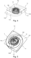
- FIG. 4 a perspective view of a further embodiment of the blower 1 according to the invention is shown.
- the spiral housing 11 is divided in the axial direction into a first region 1100 and a second region 1101.
- the two spiral-shaped air guide walls 110 are arranged rotated about the axis with respect to one another, whereby the outlet openings 111 point in opposite directions.
- the impeller 120 which is accommodated in the spiral housing 11, is arranged both within the first region 1100 and in the second region 1101, whereby the air flow of the sucked-in air, which enters the impeller via the intake opening in the cover plate (not shown), is deflected by means of the blades (not shown) in the corresponding region 1100, 1101.
- the impeller 120 is arranged in the respective area 1100, 1101 such that it is located near the smallest radius formed by the arrangement of the respective spiral air guide wall 110.
- no separating plate is arranged between the areas 1100, 1101.
- FIG 5 A further schematic perspective view of the further embodiment of the fan according to the invention is shown.
- the interior of the spiral casing 11 is shown schematically again.
- the impeller 120 is arranged near the nose 1002 of the respective spiral air guide wall 110.
- the nose 1002 is arranged at the end of the spiral air guide wall 110 which defines the smallest radius of the spiral air guide wall 110.
- the blower 1 according to the invention has two outlet openings 111 and the spiral housing 11 has cover plates 112 as a boundary in addition to the spiral air guide walls 110.
Landscapes
- Engineering & Computer Science (AREA)
- Mechanical Engineering (AREA)
- General Engineering & Computer Science (AREA)
- Structures Of Non-Positive Displacement Pumps (AREA)
Claims (8)
- Soufflante (1) avec un carter en spirale (11), dans lequel est logé au moins partiellement un ventilateur (12) avec une roue mobile (120) disposée de façon rotative sur un axe, dans lequel le carter en spirale (11) comprend au moins deux parois de guidage d'air en forme de spirale (110), qui forment au moins partiellement sur le carter en spirale (11) au moins deux ouvertures de soufflage (111) et qui s'étendent d'un très petit rayon à une limitation radialement externe d'une ouverture de soufflage et dans laquelle le carter en spirale (11) est divisé dans le sens axial du ventilateur en au moins une première zone (1100) et une deuxième zone (1101), dans laquelle chaque zone (1100, 1101) est limitée au moins partiellement par une paroi de guidage d'air en forme de spirale (110), dans laquelle au moins une paroi de guidage d'air en forme de spirale (110) est agrandie en hauteur à partir du plus petit rayon, donc dans sa dimension dans le sens axial du ventilateur, caractérisée en ce que les au moins deux parois de guidage d'air en forme de spirale (110) sont disposées en étant inclinées l'une par rapport à l'autre autour de l'axe du ventilateur et en ce que les ouvertures de soufflage formées par celles-ci se trouvent dans des positions angulaires différentes autour de l'axe.
- Soufflante (1) selon la revendication 1, caractérisée en ce que les au moins deux ouvertures de soufflage (111) sont espacées l'une de l'autre.
- Soufflante (1) selon l'une des revendications 1 ou 2, caractérisée en ce qu'entre la première zone (1100) et la deuxième zone (1101) est disposée une plaque de séparation (1103).
- Soufflante (1) selon la revendication 1, caractérisée en ce que le ventilateur (12) comprend une roue mobile (120) entraînée sur l'axe, à la périphérie de laquelle sont disposées des aubes.
- Soufflante (1), selon l'une des revendications 1 à 4, caractérisée en ce que la roue mobile (120) est disposée à l'intérieur du carter en spirale (11) près du plus petit rayon, lequel résulte de la disposition de la paroi de guidage d'air en forme de spirale respective (110).
- Soufflante (1), selon l'une des revendications 1 à 5, caractérisée en ce que le carter en spirale (11) présente au moins deux disques de recouvrement (112) qui définissent à chaque fois une partie d'une ouverture de soufflage (111).
- Soufflante (1) selon la revendication 6, caractérisée en ce que dans au moins un disque de recouvrement (112) existe une grille d'aspiration (113) ou dans au moins deux disques de recouvrement (112) existe à chaque fois une grille d'aspiration (113) pour aspirer l'air dans la roue mobile (120).
- Soufflante (1) selon l'une des revendications 1 à 7, caractérisée en ce que la soufflante (1) comprend un ventilateur radial courbé vers l'avant.
Applications Claiming Priority (1)
| Application Number | Priority Date | Filing Date | Title |
|---|---|---|---|
| DE102017210758.8A DE102017210758A1 (de) | 2017-06-27 | 2017-06-27 | Gebläse |
Publications (2)
| Publication Number | Publication Date |
|---|---|
| EP3421806A1 EP3421806A1 (fr) | 2019-01-02 |
| EP3421806B1 true EP3421806B1 (fr) | 2025-03-19 |
Family
ID=62620663
Family Applications (1)
| Application Number | Title | Priority Date | Filing Date |
|---|---|---|---|
| EP18176208.9A Active EP3421806B1 (fr) | 2017-06-27 | 2018-06-06 | Ventilateur |
Country Status (3)
| Country | Link |
|---|---|
| EP (1) | EP3421806B1 (fr) |
| CN (1) | CN109139558A (fr) |
| DE (1) | DE102017210758A1 (fr) |
Families Citing this family (2)
| Publication number | Priority date | Publication date | Assignee | Title |
|---|---|---|---|---|
| EP4008909A1 (fr) * | 2020-12-01 | 2022-06-08 | Micronel AG | Turbomachine |
| TWI876182B (zh) * | 2021-12-30 | 2025-03-11 | 濾能股份有限公司 | 氣流導引裝置以及製造設備 |
Citations (2)
| Publication number | Priority date | Publication date | Assignee | Title |
|---|---|---|---|---|
| GB542468A (en) * | 1939-07-29 | 1942-01-12 | Oerlikon Maschf | Improvements in or relating to centrifugal blowers, pumps or the like |
| JP2010100108A (ja) * | 2008-10-21 | 2010-05-06 | Denso Corp | 送風機およびそれを備える車両用空調装置 |
Family Cites Families (6)
| Publication number | Priority date | Publication date | Assignee | Title |
|---|---|---|---|---|
| US4196771A (en) * | 1977-09-12 | 1980-04-08 | A/S Norlett | Ventilator with heat exchanger |
| CN2514148Y (zh) * | 2001-11-06 | 2002-10-02 | 林钧浩 | 外流风机 |
| DE102007019056A1 (de) * | 2007-04-23 | 2008-10-30 | BSH Bosch und Siemens Hausgeräte GmbH | Lüfter für Dunstabzugshaube |
| DE102007021318A1 (de) | 2007-05-07 | 2008-11-13 | BSH Bosch und Siemens Hausgeräte GmbH | Dunstabzugsgehäuse und Dunstabzugshaube |
| US20100044468A1 (en) * | 2008-06-26 | 2010-02-25 | Momentum Industries, Llc | Device for distributing volatile fluids in air |
| KR101557107B1 (ko) * | 2013-12-16 | 2015-10-02 | 한국생산기술연구원 | 다중 벌류트 시로코팬 |
-
2017
- 2017-06-27 DE DE102017210758.8A patent/DE102017210758A1/de not_active Withdrawn
-
2018
- 2018-06-06 EP EP18176208.9A patent/EP3421806B1/fr active Active
- 2018-06-26 CN CN201810668786.2A patent/CN109139558A/zh active Pending
Patent Citations (2)
| Publication number | Priority date | Publication date | Assignee | Title |
|---|---|---|---|---|
| GB542468A (en) * | 1939-07-29 | 1942-01-12 | Oerlikon Maschf | Improvements in or relating to centrifugal blowers, pumps or the like |
| JP2010100108A (ja) * | 2008-10-21 | 2010-05-06 | Denso Corp | 送風機およびそれを備える車両用空調装置 |
Also Published As
| Publication number | Publication date |
|---|---|
| CN109139558A (zh) | 2019-01-04 |
| DE102017210758A1 (de) | 2018-12-27 |
| EP3421806A1 (fr) | 2019-01-02 |
Similar Documents
| Publication | Publication Date | Title |
|---|---|---|
| DE102009039783B4 (de) | Zentrifugalgebläse | |
| EP3184826B1 (fr) | Dispositif de ventilateur | |
| EP2338581A1 (fr) | Unité de ventilateur pour ventilateur à filtre | |
| DE102005026421B4 (de) | Wärme ableitende Vorrichtung | |
| EP2602489A2 (fr) | Dispositif de ventilateur, appareil ménager et procédé de refroidissement d'un moteur d'un dispositif de ventilateur | |
| EP2350533B1 (fr) | Appareil de cuisson avec un dispositif de guidage de flux | |
| DE102018211809A1 (de) | Gehäuse für einen Ventilator und Ventilator | |
| EP3421806B1 (fr) | Ventilateur | |
| EP2159493A2 (fr) | Dispositif d'évacuation des fumées | |
| EP1458982B1 (fr) | Dispositif ventilateur | |
| EP3101350B1 (fr) | Unite de ventilateur pour hotte aspirante et hotte aspirante | |
| EP0940632B1 (fr) | Hotte d'aspiration | |
| DE19809559A1 (de) | Dunstabzugshaube | |
| DE602006000387T2 (de) | Doppelgebläseanordnung für Kraftfahrzeuge | |
| EP0942235A1 (fr) | Feu de boulanger avec boíte d'aspiration | |
| EP3450766B1 (fr) | Ventilateur pour un appareil électrique | |
| EP3683451B1 (fr) | Dispositif de guidage de flux et agencement de ventilateur pourvu de dispositif de guidage de flux | |
| DE102016204262A1 (de) | Dunstabzugsvorrichtung | |
| DE102005026423B4 (de) | Wärme ableitende Vorrichtung | |
| DE29507424U1 (de) | Zentrifugalgebläse | |
| DE102010030949B4 (de) | Elektrische Maschine | |
| EP3770510B1 (fr) | Ventilateur pour une hotte aspirante et appareil combiné | |
| DE69018653T2 (de) | Raumlüfter. | |
| DE102005013806A1 (de) | Dunstabzugshaube | |
| EP4298384B1 (fr) | Hotte aspirante |
Legal Events
| Date | Code | Title | Description |
|---|---|---|---|
| PUAI | Public reference made under article 153(3) epc to a published international application that has entered the european phase |
Free format text: ORIGINAL CODE: 0009012 |
|
| STAA | Information on the status of an ep patent application or granted ep patent |
Free format text: STATUS: THE APPLICATION HAS BEEN PUBLISHED |
|
| AK | Designated contracting states |
Kind code of ref document: A1 Designated state(s): AL AT BE BG CH CY CZ DE DK EE ES FI FR GB GR HR HU IE IS IT LI LT LU LV MC MK MT NL NO PL PT RO RS SE SI SK SM TR |
|
| AX | Request for extension of the european patent |
Extension state: BA ME |
|
| STAA | Information on the status of an ep patent application or granted ep patent |
Free format text: STATUS: REQUEST FOR EXAMINATION WAS MADE |
|
| 17P | Request for examination filed |
Effective date: 20190702 |
|
| RBV | Designated contracting states (corrected) |
Designated state(s): AL AT BE BG CH CY CZ DE DK EE ES FI FR GB GR HR HU IE IS IT LI LT LU LV MC MK MT NL NO PL PT RO RS SE SI SK SM TR |
|
| STAA | Information on the status of an ep patent application or granted ep patent |
Free format text: STATUS: EXAMINATION IS IN PROGRESS |
|
| 17Q | First examination report despatched |
Effective date: 20210610 |
|
| GRAP | Despatch of communication of intention to grant a patent |
Free format text: ORIGINAL CODE: EPIDOSNIGR1 |
|
| STAA | Information on the status of an ep patent application or granted ep patent |
Free format text: STATUS: GRANT OF PATENT IS INTENDED |
|
| RIC1 | Information provided on ipc code assigned before grant |
Ipc: F04D 29/70 20060101ALN20240912BHEP Ipc: F04D 29/42 20060101ALI20240912BHEP Ipc: F04D 25/08 20060101AFI20240912BHEP |
|
| INTG | Intention to grant announced |
Effective date: 20240920 |
|
| GRAJ | Information related to disapproval of communication of intention to grant by the applicant or resumption of examination proceedings by the epo deleted |
Free format text: ORIGINAL CODE: EPIDOSDIGR1 |
|
| STAA | Information on the status of an ep patent application or granted ep patent |
Free format text: STATUS: EXAMINATION IS IN PROGRESS |
|
| GRAP | Despatch of communication of intention to grant a patent |
Free format text: ORIGINAL CODE: EPIDOSNIGR1 |
|
| STAA | Information on the status of an ep patent application or granted ep patent |
Free format text: STATUS: GRANT OF PATENT IS INTENDED |
|
| INTC | Intention to grant announced (deleted) | ||
| RIC1 | Information provided on ipc code assigned before grant |
Ipc: F04D 29/70 20060101ALN20241031BHEP Ipc: F04D 29/42 20060101ALI20241031BHEP Ipc: F04D 25/08 20060101AFI20241031BHEP |
|
| INTG | Intention to grant announced |
Effective date: 20241112 |
|
| GRAS | Grant fee paid |
Free format text: ORIGINAL CODE: EPIDOSNIGR3 |
|
| GRAA | (expected) grant |
Free format text: ORIGINAL CODE: 0009210 |
|
| STAA | Information on the status of an ep patent application or granted ep patent |
Free format text: STATUS: THE PATENT HAS BEEN GRANTED |
|
| AK | Designated contracting states |
Kind code of ref document: B1 Designated state(s): AL AT BE BG CH CY CZ DE DK EE ES FI FR GB GR HR HU IE IS IT LI LT LU LV MC MK MT NL NO PL PT RO RS SE SI SK SM TR |
|
| REG | Reference to a national code |
Ref country code: GB Ref legal event code: FG4D Free format text: NOT ENGLISH |
|
| REG | Reference to a national code |
Ref country code: CH Ref legal event code: EP |
|
| REG | Reference to a national code |
Ref country code: IE Ref legal event code: FG4D Free format text: LANGUAGE OF EP DOCUMENT: GERMAN |
|
| REG | Reference to a national code |
Ref country code: DE Ref legal event code: R096 Ref document number: 502018015654 Country of ref document: DE |
|
| PG25 | Lapsed in a contracting state [announced via postgrant information from national office to epo] |
Ref country code: RS Free format text: LAPSE BECAUSE OF FAILURE TO SUBMIT A TRANSLATION OF THE DESCRIPTION OR TO PAY THE FEE WITHIN THE PRESCRIBED TIME-LIMIT Effective date: 20250619 |
|
| PG25 | Lapsed in a contracting state [announced via postgrant information from national office to epo] |
Ref country code: FI Free format text: LAPSE BECAUSE OF FAILURE TO SUBMIT A TRANSLATION OF THE DESCRIPTION OR TO PAY THE FEE WITHIN THE PRESCRIBED TIME-LIMIT Effective date: 20250319 |
|
| PGFP | Annual fee paid to national office [announced via postgrant information from national office to epo] |
Ref country code: DE Payment date: 20250630 Year of fee payment: 8 |
|
| REG | Reference to a national code |
Ref country code: LT Ref legal event code: MG9D |
|
| PG25 | Lapsed in a contracting state [announced via postgrant information from national office to epo] |
Ref country code: NO Free format text: LAPSE BECAUSE OF FAILURE TO SUBMIT A TRANSLATION OF THE DESCRIPTION OR TO PAY THE FEE WITHIN THE PRESCRIBED TIME-LIMIT Effective date: 20250619 |
|
| PG25 | Lapsed in a contracting state [announced via postgrant information from national office to epo] |
Ref country code: HR Free format text: LAPSE BECAUSE OF FAILURE TO SUBMIT A TRANSLATION OF THE DESCRIPTION OR TO PAY THE FEE WITHIN THE PRESCRIBED TIME-LIMIT Effective date: 20250319 |
|
| PG25 | Lapsed in a contracting state [announced via postgrant information from national office to epo] |
Ref country code: LV Free format text: LAPSE BECAUSE OF FAILURE TO SUBMIT A TRANSLATION OF THE DESCRIPTION OR TO PAY THE FEE WITHIN THE PRESCRIBED TIME-LIMIT Effective date: 20250319 |
|
| PG25 | Lapsed in a contracting state [announced via postgrant information from national office to epo] |
Ref country code: GR Free format text: LAPSE BECAUSE OF FAILURE TO SUBMIT A TRANSLATION OF THE DESCRIPTION OR TO PAY THE FEE WITHIN THE PRESCRIBED TIME-LIMIT Effective date: 20250620 Ref country code: BG Free format text: LAPSE BECAUSE OF FAILURE TO SUBMIT A TRANSLATION OF THE DESCRIPTION OR TO PAY THE FEE WITHIN THE PRESCRIBED TIME-LIMIT Effective date: 20250319 |
|
| PGFP | Annual fee paid to national office [announced via postgrant information from national office to epo] |
Ref country code: TR Payment date: 20250605 Year of fee payment: 8 |
|
| REG | Reference to a national code |
Ref country code: NL Ref legal event code: MP Effective date: 20250319 |
|
| PG25 | Lapsed in a contracting state [announced via postgrant information from national office to epo] |
Ref country code: NL Free format text: LAPSE BECAUSE OF FAILURE TO SUBMIT A TRANSLATION OF THE DESCRIPTION OR TO PAY THE FEE WITHIN THE PRESCRIBED TIME-LIMIT Effective date: 20250319 |
|
| PG25 | Lapsed in a contracting state [announced via postgrant information from national office to epo] |
Ref country code: SE Free format text: LAPSE BECAUSE OF FAILURE TO SUBMIT A TRANSLATION OF THE DESCRIPTION OR TO PAY THE FEE WITHIN THE PRESCRIBED TIME-LIMIT Effective date: 20250319 |
|
| PG25 | Lapsed in a contracting state [announced via postgrant information from national office to epo] |
Ref country code: SM Free format text: LAPSE BECAUSE OF FAILURE TO SUBMIT A TRANSLATION OF THE DESCRIPTION OR TO PAY THE FEE WITHIN THE PRESCRIBED TIME-LIMIT Effective date: 20250319 |
|
| PG25 | Lapsed in a contracting state [announced via postgrant information from national office to epo] |
Ref country code: ES Free format text: LAPSE BECAUSE OF FAILURE TO SUBMIT A TRANSLATION OF THE DESCRIPTION OR TO PAY THE FEE WITHIN THE PRESCRIBED TIME-LIMIT Effective date: 20250319 Ref country code: PT Free format text: LAPSE BECAUSE OF FAILURE TO SUBMIT A TRANSLATION OF THE DESCRIPTION OR TO PAY THE FEE WITHIN THE PRESCRIBED TIME-LIMIT Effective date: 20250721 |
|
| PG25 | Lapsed in a contracting state [announced via postgrant information from national office to epo] |
Ref country code: PL Free format text: LAPSE BECAUSE OF FAILURE TO SUBMIT A TRANSLATION OF THE DESCRIPTION OR TO PAY THE FEE WITHIN THE PRESCRIBED TIME-LIMIT Effective date: 20250319 |
|
| PGFP | Annual fee paid to national office [announced via postgrant information from national office to epo] |
Ref country code: IT Payment date: 20250702 Year of fee payment: 8 |
|
| PG25 | Lapsed in a contracting state [announced via postgrant information from national office to epo] |
Ref country code: EE Free format text: LAPSE BECAUSE OF FAILURE TO SUBMIT A TRANSLATION OF THE DESCRIPTION OR TO PAY THE FEE WITHIN THE PRESCRIBED TIME-LIMIT Effective date: 20250319 Ref country code: CZ Free format text: LAPSE BECAUSE OF FAILURE TO SUBMIT A TRANSLATION OF THE DESCRIPTION OR TO PAY THE FEE WITHIN THE PRESCRIBED TIME-LIMIT Effective date: 20250319 |
|
| PG25 | Lapsed in a contracting state [announced via postgrant information from national office to epo] |
Ref country code: RO Free format text: LAPSE BECAUSE OF FAILURE TO SUBMIT A TRANSLATION OF THE DESCRIPTION OR TO PAY THE FEE WITHIN THE PRESCRIBED TIME-LIMIT Effective date: 20250319 |
|
| PG25 | Lapsed in a contracting state [announced via postgrant information from national office to epo] |
Ref country code: SK Free format text: LAPSE BECAUSE OF FAILURE TO SUBMIT A TRANSLATION OF THE DESCRIPTION OR TO PAY THE FEE WITHIN THE PRESCRIBED TIME-LIMIT Effective date: 20250319 |
|
| PG25 | Lapsed in a contracting state [announced via postgrant information from national office to epo] |
Ref country code: IS Free format text: LAPSE BECAUSE OF FAILURE TO SUBMIT A TRANSLATION OF THE DESCRIPTION OR TO PAY THE FEE WITHIN THE PRESCRIBED TIME-LIMIT Effective date: 20250719 |
|
| REG | Reference to a national code |
Ref country code: DE Ref legal event code: R097 Ref document number: 502018015654 Country of ref document: DE |
|
| PG25 | Lapsed in a contracting state [announced via postgrant information from national office to epo] |
Ref country code: DK Free format text: LAPSE BECAUSE OF FAILURE TO SUBMIT A TRANSLATION OF THE DESCRIPTION OR TO PAY THE FEE WITHIN THE PRESCRIBED TIME-LIMIT Effective date: 20250319 |
|
| PLBE | No opposition filed within time limit |
Free format text: ORIGINAL CODE: 0009261 |
|
| STAA | Information on the status of an ep patent application or granted ep patent |
Free format text: STATUS: NO OPPOSITION FILED WITHIN TIME LIMIT |
|
| REG | Reference to a national code |
Ref country code: CH Ref legal event code: H13 Free format text: ST27 STATUS EVENT CODE: U-0-0-H10-H13 (AS PROVIDED BY THE NATIONAL OFFICE) Effective date: 20260127 |
|
| REG | Reference to a national code |
Ref country code: CH Ref legal event code: L10 Free format text: ST27 STATUS EVENT CODE: U-0-0-L10-L00 (AS PROVIDED BY THE NATIONAL OFFICE) Effective date: 20260128 |
|
| PG25 | Lapsed in a contracting state [announced via postgrant information from national office to epo] |
Ref country code: MC Free format text: LAPSE BECAUSE OF FAILURE TO SUBMIT A TRANSLATION OF THE DESCRIPTION OR TO PAY THE FEE WITHIN THE PRESCRIBED TIME-LIMIT Effective date: 20250319 |
|
| PG25 | Lapsed in a contracting state [announced via postgrant information from national office to epo] |
Ref country code: LU Free format text: LAPSE BECAUSE OF NON-PAYMENT OF DUE FEES Effective date: 20250606 |
|
| 26N | No opposition filed |
Effective date: 20251222 |
|
| GBPC | Gb: european patent ceased through non-payment of renewal fee |
Effective date: 20250619 |
|
| REG | Reference to a national code |
Ref country code: BE Ref legal event code: MM Effective date: 20250630 |
|
| PG25 | Lapsed in a contracting state [announced via postgrant information from national office to epo] |
Ref country code: GB Free format text: LAPSE BECAUSE OF NON-PAYMENT OF DUE FEES Effective date: 20250619 |
|
| PG25 | Lapsed in a contracting state [announced via postgrant information from national office to epo] |
Ref country code: IE Free format text: LAPSE BECAUSE OF NON-PAYMENT OF DUE FEES Effective date: 20250606 |
|
| PG25 | Lapsed in a contracting state [announced via postgrant information from national office to epo] |
Ref country code: BE Free format text: LAPSE BECAUSE OF NON-PAYMENT OF DUE FEES Effective date: 20250630 |
|
| PG25 | Lapsed in a contracting state [announced via postgrant information from national office to epo] |
Ref country code: FR Free format text: LAPSE BECAUSE OF NON-PAYMENT OF DUE FEES Effective date: 20250630 |