EP3421856A1 - Raccord de tuyauterie - Google Patents
Raccord de tuyauterie Download PDFInfo
- Publication number
- EP3421856A1 EP3421856A1 EP17178823.5A EP17178823A EP3421856A1 EP 3421856 A1 EP3421856 A1 EP 3421856A1 EP 17178823 A EP17178823 A EP 17178823A EP 3421856 A1 EP3421856 A1 EP 3421856A1
- Authority
- EP
- European Patent Office
- Prior art keywords
- tube
- connection
- rotation
- tubular
- pipe
- Prior art date
- Legal status (The legal status is an assumption and is not a legal conclusion. Google has not performed a legal analysis and makes no representation as to the accuracy of the status listed.)
- Granted
Links
Images





Classifications
-
- F—MECHANICAL ENGINEERING; LIGHTING; HEATING; WEAPONS; BLASTING
- F16—ENGINEERING ELEMENTS AND UNITS; GENERAL MEASURES FOR PRODUCING AND MAINTAINING EFFECTIVE FUNCTIONING OF MACHINES OR INSTALLATIONS; THERMAL INSULATION IN GENERAL
- F16L—PIPES; JOINTS OR FITTINGS FOR PIPES; SUPPORTS FOR PIPES, CABLES OR PROTECTIVE TUBING; MEANS FOR THERMAL INSULATION IN GENERAL
- F16L19/00—Joints in which sealing surfaces are pressed together by means of a member, e.g. a swivel nut, screwed on, or into, one of the joint parts
- F16L19/02—Pipe ends provided with collars or flanges, integral with the pipe or not, pressed together by a screwed member
- F16L19/0206—Pipe ends provided with collars or flanges, integral with the pipe or not, pressed together by a screwed member the collar not being integral with the pipe
-
- F—MECHANICAL ENGINEERING; LIGHTING; HEATING; WEAPONS; BLASTING
- F16—ENGINEERING ELEMENTS AND UNITS; GENERAL MEASURES FOR PRODUCING AND MAINTAINING EFFECTIVE FUNCTIONING OF MACHINES OR INSTALLATIONS; THERMAL INSULATION IN GENERAL
- F16L—PIPES; JOINTS OR FITTINGS FOR PIPES; SUPPORTS FOR PIPES, CABLES OR PROTECTIVE TUBING; MEANS FOR THERMAL INSULATION IN GENERAL
- F16L19/00—Joints in which sealing surfaces are pressed together by means of a member, e.g. a swivel nut, screwed on, or into, one of the joint parts
- F16L19/02—Pipe ends provided with collars or flanges, integral with the pipe or not, pressed together by a screwed member
- F16L19/0212—Pipe ends provided with collars or flanges, integral with the pipe or not, pressed together by a screwed member using specially adapted sealing means
- F16L19/0225—Pipe ends provided with collars or flanges, integral with the pipe or not, pressed together by a screwed member using specially adapted sealing means without sealing rings
Definitions
- the present invention relates to a pipe joint and a method for connecting pipe elements of a pipe joint.
- EP 2 212 593 B1 is a sealing compound in which in each case a frontal toothing is attached to the two pipe elements to be connected.
- the meshing of the teeth when closing the pipe connection ensures that the sealing connection is secured against rotation.
- the sealing compound also has a separate seal.
- the seal is pressed when closing the pipe connection by means of a hollow nut which is mounted on one of the pipe elements and is screwed onto an external thread attached to the other pipe element. In this case, the seal deforms, whereby the desired sealing effect is achieved. Since the teeth must interlock when closing the sealing connection, the pipe elements are to align exactly with each other when closing the sealing connection, whereby the effort in assembling the sealing connection is significantly increased.
- the pipe elements can only be interconnected in predetermined positions, ie the relative orientation of the pipe elements relative to one another is predetermined by the position in which meshing of the teeth is possible. This is particularly problematic if the pipe elements are not rotationally symmetrical, for example curved pipe elements or pipe elements connected to connecting elements.
- the teeth must be inserted into each other. The required movement of the tubular elements increases the effort in assembling the sealing compound significantly. This is particularly the case when assembling the sealing connection under tight space conditions or must be made in hard to reach places, so that assembling in such cases may even be impossible.
- the deformation of the seal when closing the sealing compound with the consequence that the seal can not be reused after the sealing connection has been disassembled again, or that when reused a significantly lower sealing effect is expected.
- Conventional pipe joints particularly conventional stainless steel pipe joints, require the use of a lubricant.
- the lubricant must be applied before the first use and every reuse of a pipe joint clamp ring.
- a lubricant for example, grease or silver are used.
- An object of the present invention is to provide an improved pipe joint and method for joining pipe members of a pipe joint.
- the pipe connection comprises a first pipe element with a first channel for the passage of a flowing medium, a connection element and an anti-rotation element, wherein the connection element is formed, a second pipe element, the second Has channel for passing the flowing medium, to connect with the first tube member via a flange provided on the second tube member, so that the flowing medium can flow between the first channel and the second channel, wherein the anti-rotation element is attachable to the second tube element and is formed in engagement with the first tubular element for preventing rotation of the first tubular element relative to the second tubular element, wherein in a first state in which the anti-rotation element is disengaged from the first tubular element, the anti-rotation element is rotatable relative to the second tubular element, and wherein, in a second state in which the anti-rotation element is engaged with the first tubular element, the first tubular element is connectable to the second tubular element by means of the connecting element via the flange so that the first tubular element and the second tubular element against rotation
- a pipe element is a component which has a channel through which a flowing medium can be passed.
- a pipe element may be a pipe.
- the first and second pipe element and the pipe connection may for example be part of a line for conducting a fluid or part of a vacuum line such as an ultra-high vacuum line.
- connection is preferably tight for the respective flowing medium and the respective pressure conditions, so that the flowing medium in the region of the pipe connection can not escape substantially or that in the case of negative pressure in the pipe elements in the region of the pipe connection no substances can penetrate.
- a flowing medium may be, for example, a fluid.
- the term "fluid" includes gases, liquids and mixtures of gases and / or liquids.
- the flowing medium may also be another flowable substance, for example an aerosol or a dispersion.
- the flowing medium may have ambient pressure, overpressure or negative pressure.
- the anti-rotation element in the first state, is rotatable relative to the second tube member, it is for example possible to align the first tube member and the second tube element to each other, without paying attention to a particular orientation of the anti-rotation element, which not only the effort in Assembling significantly reduced, but also a greater freedom of relative orientation, which can take the pipe elements after assembling the pipe joint to each other allowed. It is thereby also possible to easily position the first engagement structure by turning the anti-rotation element so that it can be brought into engagement with the second engagement structure, for example by displacing the anti-rotation element.
- the anti-rotation element into engagement with the first tubular element without having to move the second tubular element and the first tubular element relative to one another.
- the effort in assembling is significantly reduced, especially if the assembly has to be done in confined spaces or in hard to reach places.
- the first state is preferably present first and the second state at a later time.
- the inventive pipe connection can do without the use of lubricants and therefore be completely degreased and cleaned cleaned. This allows use under clean and clean room conditions and under conditions with high hygiene requirements.
- the pipe connection according to the invention can furthermore manage without the use of additional seals.
- additional seals and lubricants By dispensing with additional seals and lubricants, not only the disadvantageous use of lubricants and / or wearing parts for economic and ecological reasons is avoided.
- this is the temperature range in which the pipe connection with a suitable selection of the materials from which the components of the pipe joint is used, very large, for example, from -250 ° C or lower to 285 ° C or higher, preferably -273 ° C. up to 450 ° C.
- the pressure range in which the pipe connection can be used with a suitable selection of materials is very large, for example, from ultra-high vacuum to high pressure.
- the pipe connection according to the invention is designed such that it has no dead volumes. Furthermore, the inner bores of the tubular elements and the clamping ring are matched to each other, so that no disturbing transitions are present and the pipe connection is streamlined.
- the flange of the inventive pipe joint is formed by a clamping ring, which is preferably attached to the end of the second pipe element facing the first pipe element.
- a clamping ring which is preferably attached to the end of the second pipe element facing the first pipe element.
- the clamping ring in connecting the second tubular element with the first tubular element in the first pipe element facing portion not or irreversibly deformed to a not significant extent.
- the flange 50 is not irreversibly deformed during assembly or to a not significant extent. This makes it possible, for example, to reuse the clamping ring after the pipe connection has been reopened without significantly deteriorating the sealing effect of the clamping ring.
- the sealing surface of the clamping ring is flat in an inner, preferably annular region and runs obliquely in an outer region. This makes it possible, for example, that the sealing effect is maintained, even if it increases with the number of repeat assemblies, i. Reuse of the clamping ring, plastic deformation of the clamping ring should also come in the area of the flange. In this case, the seal would centripetally migrate outward with increasing number of Wiederholmontagen on the sealing surface.
- the second tubular element is also irreversibly deformed in the region of its end, in particular constricted, so that the clamping ring remains positively connected to the second tubular element when the pipe connection is opened again.
- an inner surface of the clamping ring is pressed by the anti-rotation element against an outer surface of the second tube member in the region of its end to fix the clamping ring on the second tube member when the first tube member and the second tube member connected to each other, and the clamping ring clamped by a cone structure of the anti-rotation element.
- the clamping ring fixed to the second tube member and the flange and thus the second tube member secured against rotation relative to the anti-rotation, ie, the interaction of the anti-rotation with the flange or the clamping ring inhibits or prevents a corresponding rotation.
- the flange can preferably also be formed integrally with the second tubular element.
- the second tube element is preferably a weld-on nipple and / or a connection nipple.
- the anti-rotation element in the first state along at least a portion of the second tubular element is displaceable.
- a movement with which the anti-rotation element is positioned relative to the first tube element out.
- the anti-rotation element is indeed rotatable relative to the second tubular element, but not displaceable along the second tubular element.
- This can be realized, for example, by the anti-rotation element being held by an annular groove or cotter pins attached to the outer surface of the second tubular element.
- the anti-rotation element is annular and has a first engagement structure.
- the first engagement structure in an axial direction projections and / or depressions, which with a provided on the first tubular element second engagement structure, preferably complementary recesses and / or projections, can cooperate. As a result, for example, a secure, positive connection between the anti-rotation element and the first tubular element can be produced.
- first engagement structure prefferably have projections and the second engagement structure to have depressions, or for the first engagement structure to have recesses and the second engagement structure to have projections, or for both the first engagement structure and the second engagement structure to have both projections and recesses.
- the first and second engagement structures may alternatively be formed other than by protrusions and recesses, it also being possible to engage the first and second engagement structures with each other to prevent the rotation of the anti-rotation member from the first tube member.
- the first and second engagement structure may be formed as polygon structures that allow a positive engagement.
- the first and second engagement structure can also be designed, for example, as roughened or corrugated surfaces, so that the first and second engagement structure can engage in one another by frictional engagement.
- first engagement structure and the second engagement structure can preferably be brought into engagement with one another by displacing the rotation-preventing element along the second tubular element in the direction of the second engagement structure. Thereby, for example, a movement, with which the first and the second engagement structure are brought into engagement, out.
- the anti-rotation element have a first abutment surface against which in the second state Terminal member presses, and a second abutment surface, which presses against the flange in the second state.
- the anti-rotation element it is possible, for example, to load the anti-rotation element in the direction of the first tubular element with a force by which the first engagement structure and the second engagement structure are held in engagement, and to press an inner surface of the clamping ring against an outer surface of the second tubular element to the To fix clamping ring on the second pipe element.
- connection element is rotatable relative to the anti-rotation element until it reaches a fixed connection between the first pipe element and the second pipe element.
- a torque acting on the connection element for rotating the connection element is not transmitted to the second pipe element or is transmitted to a non-essential extent.
- the sealing surfaces of the pipe joint shear together which would affect the sealing effect and reusability of the clamping ring or the connecting nipple or the welding nipple and possibly lead to a cold welding of the sealing surfaces.
- a load of the second tube member and damage of the second tube member by torsion can be avoided, even if it is the second tube member is a torsion-sensitive component such as a metal corrugated hose.
- the sealed connection between the first pipe element and the second pipe element can be loosened again to separate the first pipe element and the second pipe element from each other, wherein the first pipe element and the second pipe element can be tightly connected after loosening again, and wherein the Loosening and reconnecting is preferably repeatable. More preferably, such repeatable release and reconnection is at least twenty times repeatable. Due to the repeatability, it is possible, for example, to reduce or even avoid the consumption of wearing parts. In addition, it can be reduced by the fact that the clamping ring does not need to be replaced, for example, the Häwandaufwand when loosening and reconnecting the pipe joint.
- the second connection element has a second connection structure, which is designed to cooperate with a first connection structure provided on the first tube element.
- the connection structure and the first tube element can be connected to each other without the use of separate components.
- the connection element is displaceable relative to the first tube element and the second tube element, as long as the first and the second connection structure do not interact. As a result, for example, a movement with which the connection element is positioned relative to the first tube element, out.
- connection element is designed as a union nut, wherein the first and the second connection structure are threaded.
- the connecting element to receive the anti-rotation element and the flange in its interior and to press an inner surface of the clamping ring against an outer surface of the second tubular element when connecting the first and second connecting structures.
- first tube element and the connection element can be connected to one another in another way.
- first and second connection structure may be formed as a bayonet closure.
- a connection can also be made, for example, by means of a clamp which is applied to the first tubular element and the connecting element.
- the first tubular element comprises a first planar sealing surface
- the flange comprises a second planar sealing surface, which rests in the connected state of the first tubular element and the second tubular element close to the first sealing surface.
- the first sealing surface and the second sealing surface are metallic and / or the first and / or the second sealing surface are coated.
- a particularly good sealing effect can be achieved.
- this can give a particularly good reusability of the clamping ring.
- Particularly preferred is a coating based on PTFE.
- the pipe connection prefferably comprise the second pipe element.
- the inventive method optionally further comprises the step of attaching a clamping ring to the second tubular element to form the flange.
- the second tube element is preferably moved toward the first tube element for positioning in the axial and / or radial direction to the tube axis.
- the term "radial direction" refers to the direction of the radius of the often circular cross section of the tubular elements, but is used in an analogous manner in the case of non-circular cross sections.
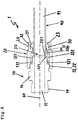
- Fig. 1 an exploded view of the pipe joint 1 according to a first embodiment of the present invention is shown.
- the pipe joint 1 comprises a first pipe element 10, which has a channel 11 for the passage of a flowing medium.
- the first tube element 10 also has a first connection structure 12.
- the pipe joint 1 further comprises a connection element 20 which has a second connection structure 22.
- the connection element 20 is preferably a union nut and in the case of the second connection structure 22 an internal thread which is in the form of an external thread formed first connecting structure 12 can cooperate to produce between the connection element 20 and the first tube member 10 a screw connection.
- the first tubular element 10 and the connecting element 20 preferably have polygonal structures 16, 26 at least in a partial region of their outer surfaces, which facilitate the manufacture of the screw connection by hand and / or make it possible to attach suitable tools such as wrenches. Alternatively or additionally, roughened or corrugated structures may be provided for this purpose.
- a second tubular element 40 is shown.
- the second pipe element 40 has a second channel 41 for passing the flowing medium. It is exemplified as a pipe.
- the second tube member 40 is preferably not considered as part of the pipe joint 1, but as a component that can cooperate with the pipe joint 1 to produce a tight connection between the first pipe member 10 and the second pipe member 40.
- the pipe joint 1 further comprises an anti-rotation element 30.
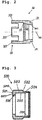
- Fig. 2 is a schematic sectional view of the anti-rotation element 30 is shown.
- the anti-rotation member 30 has a first engagement structure 33 which is formed to cooperate with a second engagement structure 13 provided on the first tube member 10 to prevent the anti-rotation member 30 from rotating relative to the first tube member.
- the anti-rotation element 30 is preferably annular, wherein the ring axis in the assembled state of the pipe joint 1 of the common axis 60 of the first and the second channel 11, 41 corresponds.
- the first engagement structure 33 includes a plurality of protrusions 331 extending in the axial direction of the anti-rotation member 30. For example, four projections 331 may be provided.
- the second engagement structure 13 comprises a corresponding number of recesses 131.
- the number of protrusions 331 and recesses 131 is basically arbitrary.
- the illustration of four protrusions 331 and four recesses 131 is merely exemplary. It is sufficient if a projection 331 and a recess 131 are provided.
- the anti-rotation element 30 further has at least one first abutment surface 31 in the region of its outer surface on the side opposite the first engagement structure 33.
- the first abutment surface 31 is formed as an end face of a shoulder of the outer surface of the anti-rotation element 30.
- the anti-rotation element 30 then has, on the side opposite the first engagement structure 33, a region 34 with a smaller outer diameter. It is preferred that the outer diameter of the region 34 is selected so that the region 34 in the assembled state of the pipe joint 1 in a through hole 23 on the first tube element 10 facing away from the connecting element 20 is received.
- the anti-rotation element has a region 34 with a smaller outer diameter
- the outer diameter of the region 34 is in each case selected so that the region 34 is received in the assembled state of the pipe joint 1 in the through hole 23 of the connecting element 20.
- the anti-rotation element 30 further has at least one second abutment surface 32 in the region of its inner surface.
- the second abutment surface 32 is formed as a conical surface, wherein the inner surface of the anti-rotation element 30 tapers in a partial region in the direction of the first engagement structure 33 opposite side.
- the anti-rotation element 30 preferably also has, in the region of its inner surface, a taper 35, which is arranged between the second abutment surface 32 and the first engagement structure 33.
- the pipe joint 1 further comprises a clamping ring 500.
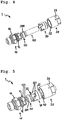
- Fig. 3 is a schematic sectional view of the clamping ring 500 is shown.
- the clamping ring 500 has a larger outer diameter than the second tube member 40 and is adapted to be attached to one end 42 of the second tube member 40, for example.
- the clamping ring 500 preferably has a projection 506, against which the end 42 abuts when the clamping ring 500 is attached to the second tube member 40, for example by placing or plugging.
- a flange 50 is formed at the end 42 of the second tube member 40.
- the flange 50 is thus an annular widened outer surface in the region of the end 42 of the second tube member 40.
- the second tube member 40 is sealed to the first tube member 10.
- the clamping ring 500 has at its in the closed state of the pipe connection to the first pipe element 10 facing the end of a second sealing surface 501.
- the second sealing surface 501 is designed to cooperate with a first sealing surface 101 of the first tubular element 10 in order to produce a sealed connection between the first and the second tubular element 10, 40 in the closed state of the tubular connection 1.
- the second sealing surface 501 is planar at least in an inner, insbesondre annular region 5011 and designed so that it is perpendicular or substantially perpendicular to the common axis 60 of the first and second channel 11, 41 in the assembled state of the pipe joint 1. More preferably, the sealing surface 501 extends obliquely, i. it is formed in an outer region 5012 obliquely to the common axis 60, in particular in the form of the lateral surface of a flat truncated cone.
- the clamping ring 500 preferably does not have the same outer diameter over its entire length, but has a preferably oblique taper 502, so that the outer surface of the clamping ring 500 has a first region 503 with a larger outer diameter and a second region 504 with a smaller outer diameter.
- the first region 503 is in the assembled state of the pipe joint 1 the first Pipe element 10 facing.
- the taper 502 of the clamping ring serves as an end stop in assembling the pipe joint 1, in which the taper 502 of the clamping ring collides with the complementary taper 35 of the anti-rotation element in assembling the pipe joint when the pipe joint is fully assembled.
- the diameter of the inner surface 505 of the clamping ring is designed so that the clamping ring can be mounted on the end 42.
- the diameter of the inner surface 505 can have a recess 507, whereby a holding groove is formed which improves the engagement of the clamping ring 500 on the second tube element 40.
- Fig. 4 is a perspective view of the pipe joint 1 according to the first embodiment shown, wherein the clamping ring 500 is attached to the end 42 of the second tube member 40.
- the clamping ring 500 is preferably designed by a suitable choice of the diameter of the inner surface 505 and the first and second portions 503, 504 of the outer surface for a first tube member 10 and a second tube member 40 having the same dimension.
- the anti-rotation element 30 can be attached to the second tube element 40.
- the anti-rotation element 30 In a first state of the pipe joint 1, in which the anti-rotation element 30 is out of engagement with the first pipe element 10, the anti-rotation element 30 is rotatable relative to the second pipe element 40.
- Fig. 5 is a perspective view of the pipe joint 1 according to the first embodiment, wherein the pipe connection is in the first state.
- the connection element 20 is also mounted on the second tube element 40, but not yet connected to the first tube element 10.
- the anti-rotation element 30 is displaceable along a portion of the second tubular element 40 or along the entire second tubular element 40. By displacing the anti-rotation element 30 along the second tube element 40 in the direction of the first tube element 10
- first and second engagement structures 33, 13 may be engaged with each other.
- the first tube member 10 and the second tube member 40 are previously positioned relative to each other, so that the sealing surfaces 101, 501 are opposed to each other or touch each other.
- Fig. 6 is a perspective view of the pipe joint 1 according to the first embodiment shown, wherein the anti-rotation element 30 has been brought by displacement along the second tubular member 40 in the direction of the first tubular element in engagement.
- the connecting element 20 is not yet connected to the first pipe element 10.
- the anti-rotation element 30 When the anti-rotation element 30 is in engagement with the first tube element 10 via the first and second engagement structures 33, 13, the anti-rotation element 30 is secured against rotation relative to the first tube element 10, i. the interaction of the engagement structures 33, 13 inhibits a corresponding rotation.
- the anti-rotation element 30 and the second tube member 40 are then already secured against rotation relative to each other, so that overall the first tube member 10 and the second tube member 40 are secured against rotation relative to each other.
- the first tubular element 10 may then be preferred and the second tube member 40, however, are then also rotated relative to each other, allowing for greater freedom in assembling the tube joint 1.
- Fig. 7 is a perspective view of the pipe joint 1 according to the first embodiment in a second state, in which the pipe joint 1 is assembled and the first tube member 10 and the second tube member 40 are interconnected shown.
- the connecting element 20 is connected to the first tubular element 10 via the connecting structures 12, 22 (in FIG Fig. 7 not shown).
- the first tube member 10 and the second tube member 40 are secured against rotation relative to each other.
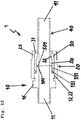
- FIG. 8 is a schematic sectional view of the pipe joint 1 according to the first embodiment shown in a hand-mounted state.
- the first pipe element 10 and the connecting element 20 are connected to each other, for example by the connecting element 20 by hand preferably without the aid of a tool has been screwed onto the first tube member 10 until the stop on the first tube member 10 in the form of a significant resistance is noticeable against the further screwing.
- the connection between the joint member 20 and the first pipe member 10 becomes tightly closed.
- first and second connection structure 12, 22 are tightened, in particular preferably by the connection element by 1 to 3, for example, 13 ⁇ 4 turns further screwed onto the first tube member 10.
- the tapers 502 and 35 which face each other in the in Fig. 8 illustrated hand-tight Do not touch mounted state, form an end stop and thus touch each other in the assembled state.
- the connecting element 20 receives in its interior the anti-rotation element 30 and the anti-rotation element 30 in its interior the flange 50.
- the connecting element 20 presses in the assembled state against the first abutment surface 31 to load the anti-rotation element 30 in the direction of the first tubular element 10 with a force by which the first engagement structure 33 and the second engagement structure 13 are held in engagement.
- the second tube member 40 is then sealed to the first tube member 10 via the flange 50.
- a force directed in the direction of the first pipe element 10 is exerted by the anti-rotation element 30 on the second pipe element 40 and / or the flange 50.
- This force is generated by pressing the anti-rotation element 30 against the flange 50 with at least one second abutment surface 32.
- the second abutment surface 32 and the clamping ring 500 it is possible to press an inner surface of the clamping ring 500 against an outer surface of the second tube member 40 in order to fix the clamping ring 500 on the second tube member 40.
- the second abutment surface 32 is preferably formed as a conical surface, whereby upon connection of the connecting element 20 with the first tube element 10, a force acting on the clamping ring 500 force, clamped by the clamping ring 500 to the second tube member 40 is being built up.
- the clamping ring 500 is fixed to the second tube member 40, but it will also be the flange 50 and thus the second Tube member 40 secured against rotation relative to the anti-rotation element 30, ie the interaction of the anti-rotation element 30 with the flange 50 and the clamping ring 500 inhibits or prevents a corresponding rotation.
- first and second tube members 10, 40 are already secured against twisting relative to each other before the first connection structure 12 and the second connection structure 22 are completely interconnected.
- the defined in claim 1 second state is then not only given when the first connection structure 12 and the second connection structure 22 are completely connected to each other, but already before, for example, when the pipe joint 10 is hand-mounted but not completely assembled.
- the second state is only given and the first and second tubular element 10, 40 are secured against rotation relative to each other only when the first connection structure 12 and the second Connection structure 22 are completely or almost completely interconnected.
- connection element 20 When connecting the first connection structure 12 to the second connection structure 22, preferably no or essentially no torque is transmitted from the connection element 20 to the flange 50 or the second tube element 40. This is achieved, for example, by the connecting element 20 sliding on the anti-rotation element 30 while it is being screwed onto the first tube element 10, and in particular while the connection is being tightened. The anti-rotation element 30 is secured against rotation relative to the first tube member 10 at this time.
- the connecting element 20 can be rotated without significant transmission of torque to the flange 50 or the second tubular element 40, it is possible, without additional sealing and without applying a lubricant, to make a tight connection between the first tubular element 10 and the second tubular element 40, without resulting in a cold welding of the sealing surfaces 101, 501 and / or the connecting structures 12, 22.
- the reusability of the clamping ring 500 and the prevention of cold welding of the sealing surfaces 101, 501 can be further improved.
- the connection element 20 and the anti-rotation element 30 By a suitable choice of material of the first connection structure 12, the connection element 20 and the anti-rotation element 30, a cold welding of the connection structure 12, 22 and a cold welding of the connection element 20 with the anti-rotation element 30 can be reduced or completely reduced. It has proven to be advantageous, the first pipe element 10 entirely and so that the first connection structure 12, the connection element 20 and the anti-rotation element 30 are each made of a suitable stainless steel. In particular, the steels with Numemrn 1.4435, 1.4404 and 1.4571 according to EN 10027-2 have proven to be suitable for the first tube member 10 and the clamping ring 500 or welding nipples, as well as the Nitronic 60 designated material for the connecting element 20, the anti-rotation element 30 proved.
- first tubular element 10 and / or the connecting element 20 and / or the anti-rotation element 30 may be solution-annealed and / or hardened.
- the clamping ring 500 or the welding nipple can also be solution-annealed and / or hardened.
- the first pipe element may be a pipe.
- the situation is shown in the accompanying drawings, for reasons of clarity, only a short pipe section 14 is shown.
- the first pipe element 10 is according to a further embodiment, the connection piece of a valve.
- this valve can be a valve for regulating the flow rate of a medium flowing through a pipeline.
- the first tube element 10 is the connecting piece of a measuring device, for example a pressure gauge.
- the first pipe element 10 is a hose nozzle onto which a hose can be plugged in order to connect it to the second pipe element 40 by means of the pipe connection 1.
- the first pipe element 10 is according to another embodiment, a connection nipple for Connecting to a second pipe element 40 and another pipe element.
- the connecting nipple is designed so that it can be connected at one end in the inventive manner with the second tube member 40 and at the other end with the other tube element.
- the connection with the further tubular element is preferably also carried out in accordance with the invention.
- connection nipple can be straight or curved. Furthermore, the connection nipple may be designed for connection to a second tube element 40 and another tube element having different dimensions. Different dimensions are to be understood as meaning different inner diameters and / or different outer diameters of the tubular elements from each other.
- connection nipple has attachment structures, by which it can be fixed in the bore of a plate-shaped element, so that it can be connected on both sides of the plate-shaped element with one tubular element.
- attachment structures can be, for example, a nut and a lock nut, which can be screwed onto an external thread mounted in the middle region of the outer surface of the connection nipple.
- the first tubular element 10 is a T-piece, a crosspiece or a connecting piece with more than four connecting pieces for connecting the second tubular element 40 with two further, three further or more than three further tubular elements.
- tees, cross pieces and connectors with more than four connecting pieces correspond to the one above described connection nipple, with the difference that instead of two connecting pieces have three, four or more than four connecting pieces.
- the first tube element 10 is a cap, i. a tubular element which is sealed at one end and can be tightly connected at the other end with a second tubular element 40 to close the second tubular element 40.
- the second tube member 40 may be, as in the first tube elements 10, for example, a pipe, the connection piece of a fitting, the connection piece of a meter, a hose nozzle, a connection nipple, a tee, a crosspiece, a connector with more than four connecting pieces or a Acting cap.
- first tubular element 10 and the second tubular element 40 can be combined with one another as desired.
- the pipe connections 1, a pipe with another pipe, a pipe with a fitting, a fitting with a measuring apparatus or a pipe can be connected to a nipple.
- FIG. 9 an exploded view of another embodiment of the inventive pipe joint 1 is shown.
- the clamping ring 500 is formed for a first tube member 10 and a second tube member 40 having different dimensions.
- Fig. 10 is a schematic sectional view of the pipe joint 1 of this embodiment shown in a hand-mounted state.
- the second tubular element 40 has a smaller inner diameter and a smaller outer diameter than the first tubular element 10.
- the Pipe connection 1 is therefore a reduction of the dimension of the first tube member 10 to the dimension of the second tube member 40 without the need for a separate adapter would be required. It is only necessary to use a clamping ring 500 suitable for the two selected pipe dimensions. That in the FIGS.
- FIG. 9 and 10 illustrated anti-rotation element 30 has the same or similar dimensions as that in example Fig. 8 shown anti-rotation element 30.
- Fig. 10 recognizable circular gap 70 between the anti-rotation element 30 and the second tube member 40 may engage the second portion 504 of the clamping ring.
- the gap 70 is closed in the finished assembled state of the pipe joint 1 to the outside through the second portion 504 of the clamping ring 500, to which the clamping ring 500 optionally has an extension which closes the gap in the assembled state.
- Fig. 11 is a schematic sectional view of another embodiment of the inventive pipe joint 1 shown in the assembled state.
- the first abutment surface 31 is formed from the end face of the anti-rotation member 30 on the opposite side of the first engagement structure 33.
- the anti-rotation element 30 has no area with a smaller outer diameter, of the Through hole 23 of the connection element 20 is received.
- the through-bore 23 is preferably adapted to the outer diameter of the second tubular element 40.
- Fig. 12 is a schematic sectional view of another embodiment of the inventive pipe joint 1 shown.
- the flange 50 is integrally formed with the second tubular member 40.
- the second pipe element 40 is to be regarded as a whole as part of the pipe joint 1.
- the second tube element 40 is, for example, a weld-on nipple.
- a weld-on nipple is a tubular element which has a flange 50 at its one end 42 and which can be connected at its other end to a further tubular element in order to provide this further tubular element with the flange 50.
- the welding of the welding nipple to the further tubular element is preferably carried out by welding, for example orbital welding.
- Fig. 13 is a schematic sectional view of another embodiment of the inventive pipe joint 1 shown in a hand-mounted state.
- Fig. 14 is a plan view of a pipe joint 1 according to this embodiment shown in a hand-mounted or assembled.
- the first tubular element 10 and the second tubular element 40 are non-rotationally symmetrical tubular elements, specifically curved tubular elements.
- the curved tubular elements each have a bent leg 15, 45.
- the bent legs 15, 45 are rotated by an angle ⁇ against each other; the angle ⁇ is in Fig. 14 located. Due to the rotatability of the second tube member 40 and the anti-rotation element 30 in the first State, it is possible to assemble the pipe joint 1 so that any angle ⁇ between 0 and 360 ° can be adjusted.
- the clamping ring 500 is attached to the end 42 of the second tube element 40.
- the anti-rotation element 30 and the connection element 20 are attached to the second tube element 40. This is done, for example, by the anti-rotation element 30 and the connection element 20 are inserted or pushed onto the second tube member 40.
- the first tube member 10 and the second tube member 40 are positioned to each other, so that the sealing surfaces 101, 501 face each other or touch each other.
- the anti-rotation member 30 is brought into engagement with the first pipe member 10 to prevent rotation of the anti-rotation member 30 relative to the first pipe member 10, ie, to secure the anti-rotation member 30 and the pipe member 10 against rotation relative to each other.
- the engagement is preferably carried out by moving the anti-rotation element 30 along the second tube member 40 in the direction of the first tube member 10.
- the connection member 20 is connected to the first tube member 10 of the type that the second tube member 40 via the flange 50 with the first pipe element 10 is connected. This is preferably done by the connection element 20 is connected by screwing hand-tight with the first tube member 10 and then tightened by it is screwed by 1 to 3, for example, 13 ⁇ 4 turns further on the first tube member 10.
- the first pipe element 10 and the second pipe element 40 are then tightly and pressure-resistant connected to each other and secured against rotation relative to each other.
- the attachment of the clamping ring 500 on the second tube element after attaching the anti-rotation element 30 and the connecting element 20 on the second tube member 40 is carried out.
- the attachment of the clamping ring 500 is omitted when the flange 50 is formed integrally with the second tube member 40.
- the attachment of the clamping ring 500, the anti-rotation element 30 and the connection element on the second tube element 40 by means of a pre-assembly device by means of a pre-assembly device.
- the clamping ring 500 is pressed onto the end 42 of the second tubular element.
- the connecting element 20 is connected by hand to the first pipe element 10.
- the connection between the first pipe element 10 and the connection element 20 is tightened, whereby the first pipe element 10 and the second pipe element 40 are tightly and pressure-proof connected to each other and secured against rotation relative to each other.
- a comparatively small rotational movement is sufficient, preferably a quarter turn of the connecting element 20 relative to the first tubular element 10.
Landscapes
- Engineering & Computer Science (AREA)
- General Engineering & Computer Science (AREA)
- Mechanical Engineering (AREA)
- Quick-Acting Or Multi-Walled Pipe Joints (AREA)
Priority Applications (2)
| Application Number | Priority Date | Filing Date | Title |
|---|---|---|---|
| EP17178823.5A EP3421856B1 (fr) | 2017-06-29 | 2017-06-29 | Raccord de tuyauterie |
| EP22194658.5A EP4119829A1 (fr) | 2017-06-29 | 2017-06-29 | Raccord de tuyauterie |
Applications Claiming Priority (1)
| Application Number | Priority Date | Filing Date | Title |
|---|---|---|---|
| EP17178823.5A EP3421856B1 (fr) | 2017-06-29 | 2017-06-29 | Raccord de tuyauterie |
Related Child Applications (2)
| Application Number | Title | Priority Date | Filing Date |
|---|---|---|---|
| EP22194658.5A Division-Into EP4119829A1 (fr) | 2017-06-29 | 2017-06-29 | Raccord de tuyauterie |
| EP22194658.5A Division EP4119829A1 (fr) | 2017-06-29 | 2017-06-29 | Raccord de tuyauterie |
Publications (2)
| Publication Number | Publication Date |
|---|---|
| EP3421856A1 true EP3421856A1 (fr) | 2019-01-02 |
| EP3421856B1 EP3421856B1 (fr) | 2022-10-19 |
Family
ID=59258120
Family Applications (2)
| Application Number | Title | Priority Date | Filing Date |
|---|---|---|---|
| EP17178823.5A Active EP3421856B1 (fr) | 2017-06-29 | 2017-06-29 | Raccord de tuyauterie |
| EP22194658.5A Pending EP4119829A1 (fr) | 2017-06-29 | 2017-06-29 | Raccord de tuyauterie |
Family Applications After (1)
| Application Number | Title | Priority Date | Filing Date |
|---|---|---|---|
| EP22194658.5A Pending EP4119829A1 (fr) | 2017-06-29 | 2017-06-29 | Raccord de tuyauterie |
Country Status (1)
| Country | Link |
|---|---|
| EP (2) | EP3421856B1 (fr) |
Citations (4)
| Publication number | Priority date | Publication date | Assignee | Title |
|---|---|---|---|---|
| US5066051A (en) * | 1990-01-23 | 1991-11-19 | Cajon Company | Anti-twist coupling assembly with biasing means |
| EP0482865A2 (fr) * | 1990-10-24 | 1992-04-29 | Cajon Company | Raccord de tuyaux |
| EP2212593B1 (fr) | 2007-10-29 | 2014-08-20 | Ludwig Hiss | Joint à expansion, en particulier pour des gaz |
| DE102013018644A1 (de) * | 2013-11-06 | 2015-05-07 | Ludwig Hiss | Vorrichtung zum koaxialen Verbinden zweier Rohrleitungen |
-
2017
- 2017-06-29 EP EP17178823.5A patent/EP3421856B1/fr active Active
- 2017-06-29 EP EP22194658.5A patent/EP4119829A1/fr active Pending
Patent Citations (4)
| Publication number | Priority date | Publication date | Assignee | Title |
|---|---|---|---|---|
| US5066051A (en) * | 1990-01-23 | 1991-11-19 | Cajon Company | Anti-twist coupling assembly with biasing means |
| EP0482865A2 (fr) * | 1990-10-24 | 1992-04-29 | Cajon Company | Raccord de tuyaux |
| EP2212593B1 (fr) | 2007-10-29 | 2014-08-20 | Ludwig Hiss | Joint à expansion, en particulier pour des gaz |
| DE102013018644A1 (de) * | 2013-11-06 | 2015-05-07 | Ludwig Hiss | Vorrichtung zum koaxialen Verbinden zweier Rohrleitungen |
Also Published As
| Publication number | Publication date |
|---|---|
| EP3421856B1 (fr) | 2022-10-19 |
| EP4119829A1 (fr) | 2023-01-18 |
Similar Documents
| Publication | Publication Date | Title |
|---|---|---|
| EP3596377B1 (fr) | Pièce de raccordement destinée à être reliée à au moins un tube et procédé de réalisation d'un assemblage | |
| DE102012019316B4 (de) | Rohrverbinder | |
| EP3066375B1 (fr) | Appareil pour assembler coaxialement deux conduites tubulaires et dispositif pour les détacher | |
| DE3923579C2 (de) | Anschlußarmatur für Rohre, insbesondere für Kunststoffrohre | |
| DE60020212T2 (de) | Rohrverbindungselement, insbesondere für kunststoffrohre | |
| EP1857724B1 (fr) | Raccord de tuyau avec tuyau déformé | |
| DE2725070A1 (de) | Rohrverbindung | |
| DE2333686A1 (de) | Vorrichtung zur verbindung glattwandiger rohre | |
| DE1525454C3 (de) | Rohr- oder schlauchkupplung | |
| EP0344582A1 (fr) | Raccord pour tuyaux ou circulent des fluides aggressifs | |
| DE202012010883U1 (de) | Anschlussflansch zum Anschweißen an ein Anlagenbauteil | |
| EP3421856B1 (fr) | Raccord de tuyauterie | |
| DE69006285T2 (de) | Verbindungsstück für Kunststoffrohre und Montageverfahren. | |
| DE2239168A1 (de) | Verbindung einer kunststoffmuffe mit einem kunststoffrohr | |
| DE19811500C2 (de) | Klemmringverbindung | |
| DE602004002170T2 (de) | Abgedichtete Kupplungsvorrichtung für ein Rohr mit einem mit einem Gewinde versehenen Fortsatz | |
| DE102010012523A1 (de) | Vorrichtung zum Verbinden mit einer Rohr- oder Schlauchleitung, insbesondere Klemmringverschraubung | |
| EP2006592B1 (fr) | Raccord | |
| DE3442424A1 (de) | Verbindungseinrichtung | |
| DE2421333C2 (de) | Verbindung für starre Rohre beliebiger Durchmesser | |
| EP2775178A1 (fr) | Bloc distributeur | |
| AT506991B1 (de) | Verbindungselement | |
| WO2019141810A1 (fr) | Système de raccordement de tuyaux | |
| DE102012107138A1 (de) | Rohrverbinder und Handlauf | |
| DE8908670U1 (de) | Anschlußarmatur für Rohre, insbesondere für Kunststoffrohre |
Legal Events
| Date | Code | Title | Description |
|---|---|---|---|
| PUAI | Public reference made under article 153(3) epc to a published international application that has entered the european phase |
Free format text: ORIGINAL CODE: 0009012 |
|
| STAA | Information on the status of an ep patent application or granted ep patent |
Free format text: STATUS: THE APPLICATION HAS BEEN PUBLISHED |
|
| AK | Designated contracting states |
Kind code of ref document: A1 Designated state(s): AL AT BE BG CH CY CZ DE DK EE ES FI FR GB GR HR HU IE IS IT LI LT LU LV MC MK MT NL NO PL PT RO RS SE SI SK SM TR |
|
| AX | Request for extension of the european patent |
Extension state: BA ME |
|
| STAA | Information on the status of an ep patent application or granted ep patent |
Free format text: STATUS: REQUEST FOR EXAMINATION WAS MADE |
|
| 17P | Request for examination filed |
Effective date: 20190625 |
|
| RBV | Designated contracting states (corrected) |
Designated state(s): AL AT BE BG CH CY CZ DE DK EE ES FI FR GB GR HR HU IE IS IT LI LT LU LV MC MK MT NL NO PL PT RO RS SE SI SK SM TR |
|
| RIC1 | Information provided on ipc code assigned before grant |
Ipc: F16L 19/02 20060101AFI20191220BHEP |
|
| GRAP | Despatch of communication of intention to grant a patent |
Free format text: ORIGINAL CODE: EPIDOSNIGR1 |
|
| STAA | Information on the status of an ep patent application or granted ep patent |
Free format text: STATUS: GRANT OF PATENT IS INTENDED |
|
| INTG | Intention to grant announced |
Effective date: 20200204 |
|
| GRAJ | Information related to disapproval of communication of intention to grant by the applicant or resumption of examination proceedings by the epo deleted |
Free format text: ORIGINAL CODE: EPIDOSDIGR1 |
|
| STAA | Information on the status of an ep patent application or granted ep patent |
Free format text: STATUS: REQUEST FOR EXAMINATION WAS MADE |
|
| INTC | Intention to grant announced (deleted) | ||
| STAA | Information on the status of an ep patent application or granted ep patent |
Free format text: STATUS: EXAMINATION IS IN PROGRESS |
|
| 17Q | First examination report despatched |
Effective date: 20200824 |
|
| GRAP | Despatch of communication of intention to grant a patent |
Free format text: ORIGINAL CODE: EPIDOSNIGR1 |
|
| STAA | Information on the status of an ep patent application or granted ep patent |
Free format text: STATUS: GRANT OF PATENT IS INTENDED |
|
| INTG | Intention to grant announced |
Effective date: 20220512 |
|
| GRAS | Grant fee paid |
Free format text: ORIGINAL CODE: EPIDOSNIGR3 |
|
| GRAA | (expected) grant |
Free format text: ORIGINAL CODE: 0009210 |
|
| STAA | Information on the status of an ep patent application or granted ep patent |
Free format text: STATUS: THE PATENT HAS BEEN GRANTED |
|
| AK | Designated contracting states |
Kind code of ref document: B1 Designated state(s): AL AT BE BG CH CY CZ DE DK EE ES FI FR GB GR HR HU IE IS IT LI LT LU LV MC MK MT NL NO PL PT RO RS SE SI SK SM TR |
|
| REG | Reference to a national code |
Ref country code: GB Ref legal event code: FG4D Free format text: NOT ENGLISH |
|
| REG | Reference to a national code |
Ref country code: CH Ref legal event code: EP |
|
| REG | Reference to a national code |
Ref country code: IE Ref legal event code: FG4D Free format text: LANGUAGE OF EP DOCUMENT: GERMAN |
|
| REG | Reference to a national code |
Ref country code: DE Ref legal event code: R096 Ref document number: 502017013965 Country of ref document: DE |
|
| REG | Reference to a national code |
Ref country code: AT Ref legal event code: REF Ref document number: 1525739 Country of ref document: AT Kind code of ref document: T Effective date: 20221115 |
|
| REG | Reference to a national code |
Ref country code: LT Ref legal event code: MG9D |
|
| REG | Reference to a national code |
Ref country code: NL Ref legal event code: MP Effective date: 20221019 |
|
| PG25 | Lapsed in a contracting state [announced via postgrant information from national office to epo] |
Ref country code: NL Free format text: LAPSE BECAUSE OF FAILURE TO SUBMIT A TRANSLATION OF THE DESCRIPTION OR TO PAY THE FEE WITHIN THE PRESCRIBED TIME-LIMIT Effective date: 20221019 |
|
| PG25 | Lapsed in a contracting state [announced via postgrant information from national office to epo] |
Ref country code: SE Free format text: LAPSE BECAUSE OF FAILURE TO SUBMIT A TRANSLATION OF THE DESCRIPTION OR TO PAY THE FEE WITHIN THE PRESCRIBED TIME-LIMIT Effective date: 20221019 Ref country code: PT Free format text: LAPSE BECAUSE OF FAILURE TO SUBMIT A TRANSLATION OF THE DESCRIPTION OR TO PAY THE FEE WITHIN THE PRESCRIBED TIME-LIMIT Effective date: 20230220 Ref country code: NO Free format text: LAPSE BECAUSE OF FAILURE TO SUBMIT A TRANSLATION OF THE DESCRIPTION OR TO PAY THE FEE WITHIN THE PRESCRIBED TIME-LIMIT Effective date: 20230119 Ref country code: LT Free format text: LAPSE BECAUSE OF FAILURE TO SUBMIT A TRANSLATION OF THE DESCRIPTION OR TO PAY THE FEE WITHIN THE PRESCRIBED TIME-LIMIT Effective date: 20221019 Ref country code: FI Free format text: LAPSE BECAUSE OF FAILURE TO SUBMIT A TRANSLATION OF THE DESCRIPTION OR TO PAY THE FEE WITHIN THE PRESCRIBED TIME-LIMIT Effective date: 20221019 Ref country code: ES Free format text: LAPSE BECAUSE OF FAILURE TO SUBMIT A TRANSLATION OF THE DESCRIPTION OR TO PAY THE FEE WITHIN THE PRESCRIBED TIME-LIMIT Effective date: 20221019 |
|
| PG25 | Lapsed in a contracting state [announced via postgrant information from national office to epo] |
Ref country code: RS Free format text: LAPSE BECAUSE OF FAILURE TO SUBMIT A TRANSLATION OF THE DESCRIPTION OR TO PAY THE FEE WITHIN THE PRESCRIBED TIME-LIMIT Effective date: 20221019 Ref country code: PL Free format text: LAPSE BECAUSE OF FAILURE TO SUBMIT A TRANSLATION OF THE DESCRIPTION OR TO PAY THE FEE WITHIN THE PRESCRIBED TIME-LIMIT Effective date: 20221019 Ref country code: LV Free format text: LAPSE BECAUSE OF FAILURE TO SUBMIT A TRANSLATION OF THE DESCRIPTION OR TO PAY THE FEE WITHIN THE PRESCRIBED TIME-LIMIT Effective date: 20221019 Ref country code: IS Free format text: LAPSE BECAUSE OF FAILURE TO SUBMIT A TRANSLATION OF THE DESCRIPTION OR TO PAY THE FEE WITHIN THE PRESCRIBED TIME-LIMIT Effective date: 20230219 Ref country code: HR Free format text: LAPSE BECAUSE OF FAILURE TO SUBMIT A TRANSLATION OF THE DESCRIPTION OR TO PAY THE FEE WITHIN THE PRESCRIBED TIME-LIMIT Effective date: 20221019 Ref country code: GR Free format text: LAPSE BECAUSE OF FAILURE TO SUBMIT A TRANSLATION OF THE DESCRIPTION OR TO PAY THE FEE WITHIN THE PRESCRIBED TIME-LIMIT Effective date: 20230120 |
|
| REG | Reference to a national code |
Ref country code: DE Ref legal event code: R097 Ref document number: 502017013965 Country of ref document: DE |
|
| PG25 | Lapsed in a contracting state [announced via postgrant information from national office to epo] |
Ref country code: SM Free format text: LAPSE BECAUSE OF FAILURE TO SUBMIT A TRANSLATION OF THE DESCRIPTION OR TO PAY THE FEE WITHIN THE PRESCRIBED TIME-LIMIT Effective date: 20221019 Ref country code: RO Free format text: LAPSE BECAUSE OF FAILURE TO SUBMIT A TRANSLATION OF THE DESCRIPTION OR TO PAY THE FEE WITHIN THE PRESCRIBED TIME-LIMIT Effective date: 20221019 Ref country code: EE Free format text: LAPSE BECAUSE OF FAILURE TO SUBMIT A TRANSLATION OF THE DESCRIPTION OR TO PAY THE FEE WITHIN THE PRESCRIBED TIME-LIMIT Effective date: 20221019 Ref country code: DK Free format text: LAPSE BECAUSE OF FAILURE TO SUBMIT A TRANSLATION OF THE DESCRIPTION OR TO PAY THE FEE WITHIN THE PRESCRIBED TIME-LIMIT Effective date: 20221019 Ref country code: CZ Free format text: LAPSE BECAUSE OF FAILURE TO SUBMIT A TRANSLATION OF THE DESCRIPTION OR TO PAY THE FEE WITHIN THE PRESCRIBED TIME-LIMIT Effective date: 20221019 |
|
| PLBE | No opposition filed within time limit |
Free format text: ORIGINAL CODE: 0009261 |
|
| STAA | Information on the status of an ep patent application or granted ep patent |
Free format text: STATUS: NO OPPOSITION FILED WITHIN TIME LIMIT |
|
| PG25 | Lapsed in a contracting state [announced via postgrant information from national office to epo] |
Ref country code: SK Free format text: LAPSE BECAUSE OF FAILURE TO SUBMIT A TRANSLATION OF THE DESCRIPTION OR TO PAY THE FEE WITHIN THE PRESCRIBED TIME-LIMIT Effective date: 20221019 Ref country code: AL Free format text: LAPSE BECAUSE OF FAILURE TO SUBMIT A TRANSLATION OF THE DESCRIPTION OR TO PAY THE FEE WITHIN THE PRESCRIBED TIME-LIMIT Effective date: 20221019 |
|
| 26N | No opposition filed |
Effective date: 20230720 |
|
| PG25 | Lapsed in a contracting state [announced via postgrant information from national office to epo] |
Ref country code: SI Free format text: LAPSE BECAUSE OF FAILURE TO SUBMIT A TRANSLATION OF THE DESCRIPTION OR TO PAY THE FEE WITHIN THE PRESCRIBED TIME-LIMIT Effective date: 20221019 |
|
| PG25 | Lapsed in a contracting state [announced via postgrant information from national office to epo] |
Ref country code: MC Free format text: LAPSE BECAUSE OF FAILURE TO SUBMIT A TRANSLATION OF THE DESCRIPTION OR TO PAY THE FEE WITHIN THE PRESCRIBED TIME-LIMIT Effective date: 20221019 |
|
| PG25 | Lapsed in a contracting state [announced via postgrant information from national office to epo] |
Ref country code: MC Free format text: LAPSE BECAUSE OF FAILURE TO SUBMIT A TRANSLATION OF THE DESCRIPTION OR TO PAY THE FEE WITHIN THE PRESCRIBED TIME-LIMIT Effective date: 20221019 |
|
| REG | Reference to a national code |
Ref country code: BE Ref legal event code: MM Effective date: 20230630 |
|
| GBPC | Gb: european patent ceased through non-payment of renewal fee |
Effective date: 20230629 |
|
| PG25 | Lapsed in a contracting state [announced via postgrant information from national office to epo] |
Ref country code: LU Free format text: LAPSE BECAUSE OF NON-PAYMENT OF DUE FEES Effective date: 20230629 |
|
| REG | Reference to a national code |
Ref country code: IE Ref legal event code: MM4A |
|
| PG25 | Lapsed in a contracting state [announced via postgrant information from national office to epo] |
Ref country code: LU Free format text: LAPSE BECAUSE OF NON-PAYMENT OF DUE FEES Effective date: 20230629 |
|
| PG25 | Lapsed in a contracting state [announced via postgrant information from national office to epo] |
Ref country code: IE Free format text: LAPSE BECAUSE OF NON-PAYMENT OF DUE FEES Effective date: 20230629 |
|
| PG25 | Lapsed in a contracting state [announced via postgrant information from national office to epo] |
Ref country code: IE Free format text: LAPSE BECAUSE OF NON-PAYMENT OF DUE FEES Effective date: 20230629 Ref country code: GB Free format text: LAPSE BECAUSE OF NON-PAYMENT OF DUE FEES Effective date: 20230629 |
|
| PG25 | Lapsed in a contracting state [announced via postgrant information from national office to epo] |
Ref country code: BE Free format text: LAPSE BECAUSE OF NON-PAYMENT OF DUE FEES Effective date: 20230630 |
|
| PG25 | Lapsed in a contracting state [announced via postgrant information from national office to epo] |
Ref country code: BG Free format text: LAPSE BECAUSE OF FAILURE TO SUBMIT A TRANSLATION OF THE DESCRIPTION OR TO PAY THE FEE WITHIN THE PRESCRIBED TIME-LIMIT Effective date: 20221019 |
|
| PG25 | Lapsed in a contracting state [announced via postgrant information from national office to epo] |
Ref country code: BG Free format text: LAPSE BECAUSE OF FAILURE TO SUBMIT A TRANSLATION OF THE DESCRIPTION OR TO PAY THE FEE WITHIN THE PRESCRIBED TIME-LIMIT Effective date: 20221019 |
|
| PG25 | Lapsed in a contracting state [announced via postgrant information from national office to epo] |
Ref country code: CY Free format text: LAPSE BECAUSE OF FAILURE TO SUBMIT A TRANSLATION OF THE DESCRIPTION OR TO PAY THE FEE WITHIN THE PRESCRIBED TIME-LIMIT; INVALID AB INITIO Effective date: 20170629 |
|
| PG25 | Lapsed in a contracting state [announced via postgrant information from national office to epo] |
Ref country code: HU Free format text: LAPSE BECAUSE OF FAILURE TO SUBMIT A TRANSLATION OF THE DESCRIPTION OR TO PAY THE FEE WITHIN THE PRESCRIBED TIME-LIMIT; INVALID AB INITIO Effective date: 20170629 |
|
| PG25 | Lapsed in a contracting state [announced via postgrant information from national office to epo] |
Ref country code: TR Free format text: LAPSE BECAUSE OF FAILURE TO SUBMIT A TRANSLATION OF THE DESCRIPTION OR TO PAY THE FEE WITHIN THE PRESCRIBED TIME-LIMIT Effective date: 20221019 |
|
| REG | Reference to a national code |
Ref country code: CH Ref legal event code: U11 Free format text: ST27 STATUS EVENT CODE: U-0-0-U10-U11 (AS PROVIDED BY THE NATIONAL OFFICE) Effective date: 20260105 |
|
| PGFP | Annual fee paid to national office [announced via postgrant information from national office to epo] |
Ref country code: DE Payment date: 20251211 Year of fee payment: 9 |
|
| PGFP | Annual fee paid to national office [announced via postgrant information from national office to epo] |
Ref country code: AT Payment date: 20251222 Year of fee payment: 9 |
|
| PGFP | Annual fee paid to national office [announced via postgrant information from national office to epo] |
Ref country code: IT Payment date: 20251223 Year of fee payment: 9 |
|
| PGFP | Annual fee paid to national office [announced via postgrant information from national office to epo] |
Ref country code: FR Payment date: 20251219 Year of fee payment: 9 |
|
| PGFP | Annual fee paid to national office [announced via postgrant information from national office to epo] |
Ref country code: CH Payment date: 20251222 Year of fee payment: 9 |