EP3421863B1 - Kurvenkombinierter quadratischer drucktank - Google Patents
Kurvenkombinierter quadratischer drucktank Download PDFInfo
- Publication number
- EP3421863B1 EP3421863B1 EP17756888.8A EP17756888A EP3421863B1 EP 3421863 B1 EP3421863 B1 EP 3421863B1 EP 17756888 A EP17756888 A EP 17756888A EP 3421863 B1 EP3421863 B1 EP 3421863B1
- Authority
- EP
- European Patent Office
- Prior art keywords
- pressure tank
- curve
- curved
- flat
- tension
- Prior art date
- Legal status (The legal status is an assumption and is not a legal conclusion. Google has not performed a legal analysis and makes no representation as to the accuracy of the status listed.)
- Active
Links
Images










Classifications
-
- B—PERFORMING OPERATIONS; TRANSPORTING
- B60—VEHICLES IN GENERAL
- B60K—ARRANGEMENT OR MOUNTING OF PROPULSION UNITS OR OF TRANSMISSIONS IN VEHICLES; ARRANGEMENT OR MOUNTING OF PLURAL DIVERSE PRIME-MOVERS IN VEHICLES; AUXILIARY DRIVES FOR VEHICLES; INSTRUMENTATION OR DASHBOARDS FOR VEHICLES; ARRANGEMENTS IN CONNECTION WITH COOLING, AIR INTAKE, GAS EXHAUST OR FUEL SUPPLY OF PROPULSION UNITS IN VEHICLES
- B60K15/00—Arrangement in connection with fuel supply of combustion engines or other fuel consuming energy converters, e.g. fuel cells; Mounting or construction of fuel tanks
- B60K15/03—Fuel tanks
- B60K15/03006—Gas tanks
-
- B—PERFORMING OPERATIONS; TRANSPORTING
- B60—VEHICLES IN GENERAL
- B60K—ARRANGEMENT OR MOUNTING OF PROPULSION UNITS OR OF TRANSMISSIONS IN VEHICLES; ARRANGEMENT OR MOUNTING OF PLURAL DIVERSE PRIME-MOVERS IN VEHICLES; AUXILIARY DRIVES FOR VEHICLES; INSTRUMENTATION OR DASHBOARDS FOR VEHICLES; ARRANGEMENTS IN CONNECTION WITH COOLING, AIR INTAKE, GAS EXHAUST OR FUEL SUPPLY OF PROPULSION UNITS IN VEHICLES
- B60K15/00—Arrangement in connection with fuel supply of combustion engines or other fuel consuming energy converters, e.g. fuel cells; Mounting or construction of fuel tanks
- B60K15/03—Fuel tanks
-
- B—PERFORMING OPERATIONS; TRANSPORTING
- B63—SHIPS OR OTHER WATERBORNE VESSELS; RELATED EQUIPMENT
- B63B—SHIPS OR OTHER WATERBORNE VESSELS; EQUIPMENT FOR SHIPPING
- B63B11/00—Interior subdivision of hulls
- B63B11/04—Constructional features of bunkers, e.g. structural fuel tanks, or ballast tanks, e.g. with elastic walls
-
- B—PERFORMING OPERATIONS; TRANSPORTING
- B63—SHIPS OR OTHER WATERBORNE VESSELS; RELATED EQUIPMENT
- B63B—SHIPS OR OTHER WATERBORNE VESSELS; EQUIPMENT FOR SHIPPING
- B63B17/00—Vessels parts, details, or accessories, not otherwise provided for
-
- B—PERFORMING OPERATIONS; TRANSPORTING
- B63—SHIPS OR OTHER WATERBORNE VESSELS; RELATED EQUIPMENT
- B63B—SHIPS OR OTHER WATERBORNE VESSELS; EQUIPMENT FOR SHIPPING
- B63B17/00—Vessels parts, details, or accessories, not otherwise provided for
- B63B17/0027—Tanks for fuel or the like ; Accessories therefor, e.g. tank filler caps
-
- B—PERFORMING OPERATIONS; TRANSPORTING
- B63—SHIPS OR OTHER WATERBORNE VESSELS; RELATED EQUIPMENT
- B63B—SHIPS OR OTHER WATERBORNE VESSELS; EQUIPMENT FOR SHIPPING
- B63B25/00—Load-accommodating arrangements, e.g. stowing, trimming; Vessels characterised thereby
- B63B25/02—Load-accommodating arrangements, e.g. stowing, trimming; Vessels characterised thereby for bulk goods
- B63B25/08—Load-accommodating arrangements, e.g. stowing, trimming; Vessels characterised thereby for bulk goods fluid
- B63B25/12—Load-accommodating arrangements, e.g. stowing, trimming; Vessels characterised thereby for bulk goods fluid closed
- B63B25/16—Load-accommodating arrangements, e.g. stowing, trimming; Vessels characterised thereby for bulk goods fluid closed heat-insulated
-
- F—MECHANICAL ENGINEERING; LIGHTING; HEATING; WEAPONS; BLASTING
- F17—STORING OR DISTRIBUTING GASES OR LIQUIDS
- F17C—VESSELS FOR CONTAINING OR STORING COMPRESSED, LIQUEFIED OR SOLIDIFIED GASES; FIXED-CAPACITY GAS-HOLDERS; FILLING VESSELS WITH, OR DISCHARGING FROM VESSELS, COMPRESSED, LIQUEFIED, OR SOLIDIFIED GASES
- F17C1/00—Pressure vessels, e.g. gas cylinder, gas tank, replaceable cartridge
- F17C1/02—Pressure vessels, e.g. gas cylinder, gas tank, replaceable cartridge involving reinforcing arrangements
- F17C1/08—Integral reinforcements, e.g. ribs
-
- F—MECHANICAL ENGINEERING; LIGHTING; HEATING; WEAPONS; BLASTING
- F17—STORING OR DISTRIBUTING GASES OR LIQUIDS
- F17C—VESSELS FOR CONTAINING OR STORING COMPRESSED, LIQUEFIED OR SOLIDIFIED GASES; FIXED-CAPACITY GAS-HOLDERS; FILLING VESSELS WITH, OR DISCHARGING FROM VESSELS, COMPRESSED, LIQUEFIED, OR SOLIDIFIED GASES
- F17C13/00—Details of vessels or of the filling or discharging of vessels
- F17C13/002—Details of vessels or of the filling or discharging of vessels for vessels under pressure
-
- F—MECHANICAL ENGINEERING; LIGHTING; HEATING; WEAPONS; BLASTING
- F17—STORING OR DISTRIBUTING GASES OR LIQUIDS
- F17C—VESSELS FOR CONTAINING OR STORING COMPRESSED, LIQUEFIED OR SOLIDIFIED GASES; FIXED-CAPACITY GAS-HOLDERS; FILLING VESSELS WITH, OR DISCHARGING FROM VESSELS, COMPRESSED, LIQUEFIED, OR SOLIDIFIED GASES
- F17C3/00—Vessels not under pressure
-
- B—PERFORMING OPERATIONS; TRANSPORTING
- B60—VEHICLES IN GENERAL
- B60K—ARRANGEMENT OR MOUNTING OF PROPULSION UNITS OR OF TRANSMISSIONS IN VEHICLES; ARRANGEMENT OR MOUNTING OF PLURAL DIVERSE PRIME-MOVERS IN VEHICLES; AUXILIARY DRIVES FOR VEHICLES; INSTRUMENTATION OR DASHBOARDS FOR VEHICLES; ARRANGEMENTS IN CONNECTION WITH COOLING, AIR INTAKE, GAS EXHAUST OR FUEL SUPPLY OF PROPULSION UNITS IN VEHICLES
- B60K15/00—Arrangement in connection with fuel supply of combustion engines or other fuel consuming energy converters, e.g. fuel cells; Mounting or construction of fuel tanks
- B60K15/03—Fuel tanks
- B60K15/073—Tank construction specially adapted to the vehicle
-
- B—PERFORMING OPERATIONS; TRANSPORTING
- B60—VEHICLES IN GENERAL
- B60K—ARRANGEMENT OR MOUNTING OF PROPULSION UNITS OR OF TRANSMISSIONS IN VEHICLES; ARRANGEMENT OR MOUNTING OF PLURAL DIVERSE PRIME-MOVERS IN VEHICLES; AUXILIARY DRIVES FOR VEHICLES; INSTRUMENTATION OR DASHBOARDS FOR VEHICLES; ARRANGEMENTS IN CONNECTION WITH COOLING, AIR INTAKE, GAS EXHAUST OR FUEL SUPPLY OF PROPULSION UNITS IN VEHICLES
- B60K15/00—Arrangement in connection with fuel supply of combustion engines or other fuel consuming energy converters, e.g. fuel cells; Mounting or construction of fuel tanks
- B60K15/03—Fuel tanks
- B60K2015/03032—Manufacturing of fuel tanks
-
- B—PERFORMING OPERATIONS; TRANSPORTING
- B60—VEHICLES IN GENERAL
- B60K—ARRANGEMENT OR MOUNTING OF PROPULSION UNITS OR OF TRANSMISSIONS IN VEHICLES; ARRANGEMENT OR MOUNTING OF PLURAL DIVERSE PRIME-MOVERS IN VEHICLES; AUXILIARY DRIVES FOR VEHICLES; INSTRUMENTATION OR DASHBOARDS FOR VEHICLES; ARRANGEMENTS IN CONNECTION WITH COOLING, AIR INTAKE, GAS EXHAUST OR FUEL SUPPLY OF PROPULSION UNITS IN VEHICLES
- B60K15/00—Arrangement in connection with fuel supply of combustion engines or other fuel consuming energy converters, e.g. fuel cells; Mounting or construction of fuel tanks
- B60K15/03—Fuel tanks
- B60K2015/03328—Arrangements or special measures related to fuel tanks or fuel handling
- B60K2015/03453—Arrangements or special measures related to fuel tanks or fuel handling for fixing or mounting parts of the fuel tank together
-
- F—MECHANICAL ENGINEERING; LIGHTING; HEATING; WEAPONS; BLASTING
- F17—STORING OR DISTRIBUTING GASES OR LIQUIDS
- F17C—VESSELS FOR CONTAINING OR STORING COMPRESSED, LIQUEFIED OR SOLIDIFIED GASES; FIXED-CAPACITY GAS-HOLDERS; FILLING VESSELS WITH, OR DISCHARGING FROM VESSELS, COMPRESSED, LIQUEFIED, OR SOLIDIFIED GASES
- F17C2201/00—Vessel construction, in particular geometry, arrangement or size
- F17C2201/01—Shape
- F17C2201/0147—Shape complex
-
- F—MECHANICAL ENGINEERING; LIGHTING; HEATING; WEAPONS; BLASTING
- F17—STORING OR DISTRIBUTING GASES OR LIQUIDS
- F17C—VESSELS FOR CONTAINING OR STORING COMPRESSED, LIQUEFIED OR SOLIDIFIED GASES; FIXED-CAPACITY GAS-HOLDERS; FILLING VESSELS WITH, OR DISCHARGING FROM VESSELS, COMPRESSED, LIQUEFIED, OR SOLIDIFIED GASES
- F17C2201/00—Vessel construction, in particular geometry, arrangement or size
- F17C2201/05—Size
- F17C2201/056—Small (<1 m3)
-
- F—MECHANICAL ENGINEERING; LIGHTING; HEATING; WEAPONS; BLASTING
- F17—STORING OR DISTRIBUTING GASES OR LIQUIDS
- F17C—VESSELS FOR CONTAINING OR STORING COMPRESSED, LIQUEFIED OR SOLIDIFIED GASES; FIXED-CAPACITY GAS-HOLDERS; FILLING VESSELS WITH, OR DISCHARGING FROM VESSELS, COMPRESSED, LIQUEFIED, OR SOLIDIFIED GASES
- F17C2203/00—Vessel construction, in particular walls or details thereof
- F17C2203/01—Reinforcing or suspension means
- F17C2203/011—Reinforcing means
- F17C2203/013—Reinforcing means in the vessel, e.g. columns
-
- F—MECHANICAL ENGINEERING; LIGHTING; HEATING; WEAPONS; BLASTING
- F17—STORING OR DISTRIBUTING GASES OR LIQUIDS
- F17C—VESSELS FOR CONTAINING OR STORING COMPRESSED, LIQUEFIED OR SOLIDIFIED GASES; FIXED-CAPACITY GAS-HOLDERS; FILLING VESSELS WITH, OR DISCHARGING FROM VESSELS, COMPRESSED, LIQUEFIED, OR SOLIDIFIED GASES
- F17C2221/00—Handled fluid, in particular type of fluid
- F17C2221/03—Mixtures
- F17C2221/032—Hydrocarbons
- F17C2221/033—Methane, e.g. natural gas, CNG, LNG, GNL, GNC, PLNG
-
- F—MECHANICAL ENGINEERING; LIGHTING; HEATING; WEAPONS; BLASTING
- F17—STORING OR DISTRIBUTING GASES OR LIQUIDS
- F17C—VESSELS FOR CONTAINING OR STORING COMPRESSED, LIQUEFIED OR SOLIDIFIED GASES; FIXED-CAPACITY GAS-HOLDERS; FILLING VESSELS WITH, OR DISCHARGING FROM VESSELS, COMPRESSED, LIQUEFIED, OR SOLIDIFIED GASES
- F17C2223/00—Handled fluid before transfer, i.e. state of fluid when stored in the vessel or before transfer from the vessel
- F17C2223/01—Handled fluid before transfer, i.e. state of fluid when stored in the vessel or before transfer from the vessel characterised by the phase
- F17C2223/0107—Single phase
- F17C2223/0123—Single phase gaseous, e.g. CNG, GNC
-
- F—MECHANICAL ENGINEERING; LIGHTING; HEATING; WEAPONS; BLASTING
- F17—STORING OR DISTRIBUTING GASES OR LIQUIDS
- F17C—VESSELS FOR CONTAINING OR STORING COMPRESSED, LIQUEFIED OR SOLIDIFIED GASES; FIXED-CAPACITY GAS-HOLDERS; FILLING VESSELS WITH, OR DISCHARGING FROM VESSELS, COMPRESSED, LIQUEFIED, OR SOLIDIFIED GASES
- F17C2223/00—Handled fluid before transfer, i.e. state of fluid when stored in the vessel or before transfer from the vessel
- F17C2223/01—Handled fluid before transfer, i.e. state of fluid when stored in the vessel or before transfer from the vessel characterised by the phase
- F17C2223/0146—Two-phase
- F17C2223/0153—Liquefied gas, e.g. LPG, GPL
-
- F—MECHANICAL ENGINEERING; LIGHTING; HEATING; WEAPONS; BLASTING
- F17—STORING OR DISTRIBUTING GASES OR LIQUIDS
- F17C—VESSELS FOR CONTAINING OR STORING COMPRESSED, LIQUEFIED OR SOLIDIFIED GASES; FIXED-CAPACITY GAS-HOLDERS; FILLING VESSELS WITH, OR DISCHARGING FROM VESSELS, COMPRESSED, LIQUEFIED, OR SOLIDIFIED GASES
- F17C2223/00—Handled fluid before transfer, i.e. state of fluid when stored in the vessel or before transfer from the vessel
- F17C2223/01—Handled fluid before transfer, i.e. state of fluid when stored in the vessel or before transfer from the vessel characterised by the phase
- F17C2223/0146—Two-phase
- F17C2223/0153—Liquefied gas, e.g. LPG, GPL
- F17C2223/0161—Liquefied gas, e.g. LPG, GPL cryogenic, e.g. LNG, GNL, PLNG
-
- F—MECHANICAL ENGINEERING; LIGHTING; HEATING; WEAPONS; BLASTING
- F17—STORING OR DISTRIBUTING GASES OR LIQUIDS
- F17C—VESSELS FOR CONTAINING OR STORING COMPRESSED, LIQUEFIED OR SOLIDIFIED GASES; FIXED-CAPACITY GAS-HOLDERS; FILLING VESSELS WITH, OR DISCHARGING FROM VESSELS, COMPRESSED, LIQUEFIED, OR SOLIDIFIED GASES
- F17C2260/00—Purposes of gas storage and gas handling
- F17C2260/01—Improving mechanical properties or manufacturing
- F17C2260/018—Adapting dimensions
-
- F—MECHANICAL ENGINEERING; LIGHTING; HEATING; WEAPONS; BLASTING
- F17—STORING OR DISTRIBUTING GASES OR LIQUIDS
- F17C—VESSELS FOR CONTAINING OR STORING COMPRESSED, LIQUEFIED OR SOLIDIFIED GASES; FIXED-CAPACITY GAS-HOLDERS; FILLING VESSELS WITH, OR DISCHARGING FROM VESSELS, COMPRESSED, LIQUEFIED, OR SOLIDIFIED GASES
- F17C2270/00—Applications
- F17C2270/01—Applications for fluid transport or storage
- F17C2270/0165—Applications for fluid transport or storage on the road
- F17C2270/0168—Applications for fluid transport or storage on the road by vehicles
- F17C2270/0176—Buses
-
- F—MECHANICAL ENGINEERING; LIGHTING; HEATING; WEAPONS; BLASTING
- F17—STORING OR DISTRIBUTING GASES OR LIQUIDS
- F17C—VESSELS FOR CONTAINING OR STORING COMPRESSED, LIQUEFIED OR SOLIDIFIED GASES; FIXED-CAPACITY GAS-HOLDERS; FILLING VESSELS WITH, OR DISCHARGING FROM VESSELS, COMPRESSED, LIQUEFIED, OR SOLIDIFIED GASES
- F17C2270/00—Applications
- F17C2270/01—Applications for fluid transport or storage
- F17C2270/0165—Applications for fluid transport or storage on the road
- F17C2270/0168—Applications for fluid transport or storage on the road by vehicles
- F17C2270/0178—Cars
Definitions
- the present invention relates to a polygonal pressure tank and, more particularly, to a curve-combined polygonal pressure tank that is formed by combining a flat plate and a curved surface to enhance space utilization and reduce a weight as well as to maintain high internal pressure.
- natural gas is supplied in the form of pipe-line natural gas (PNG) that is fed to a consumption place from a production place through a pipe line or in the form of liquefied natural gas (LNG) that is liquefied through a vessel when a production place and a consumption place are far from each other and, in this case, LNG is used directly as fuel of transportation such as a vessel, a bus, and an automobile as well as general uses of liquefied natural gas and, to this end, LNG is generally stored in a cylindrical pressure tank and is stored and used in a pressure tank installed in transportation.
- PNG pipe-line natural gas
- LNG liquefied natural gas
- a general cylindrical pressure tank is conveniently used in an automobile or the like due to high pressure-resistant performance and a small volume but, when a large amount of liquefied natural gas is required like in a vessel, a plurality of cylindrical pressure tanks needs to be installed and, in particular, when liquefied natural gas is also used as fuel of a vessel, more cylindrical pressure tanks need to be installed in the vessel and, thus, there is a problem in that a space occupied in the vessel is excessively increased due to an interval between the cylindrical pressure tanks when the plurality of cylindrical pressure tanks are arranged.
- Korean Patent Publication No. 10-1254788 discloses a square pressure tank configured by improving defects of the membrane or circular tank system, like in FIG. 1 of the present application.
- a cryogenic tank as disclosed in US 2014/0117163 A1 , but it was made by joining elongated lobes and had limitation to make various shape tanks.
- DE 19749950 D2 proposed a container for storing compressed gas with the connected cladding layer, but it also had limitation to make various shape tanks.
- the polygonal pressure tank advantageously and largely improves space efficiency, which is disadvantage of the conventional membrane or circular tank system, but it is required to overcome a problem in terms of its high weight.
- An object of the present invention is to provide a curve-combined polygonal pressure tank for reducing a weight while enhancing space efficiency as well as maintaining high pressure inside the pressure tank.
- Another object of the present invention is to provide a method of overcoming a structural problem when a polygonal pressure tank and a curved surface are combined.
- various embodiments of a curve-combined polygonal pressure are proposed to provide an ideal model of a curve-combined polygonal pressure tank applicable to an actual vessel.
- a pressure tank according to the present invention includes the curve-combined polygonal pressure tank in accordance with independent claim 1. Preferred embodiments can be found in the dependent claims.
- a curve-combined polygonal pressure tank according to the present invention may advantageously reduce space utilization and a weight as well as maintaining high internal pressure.
- connection portion between the curved surface and the flat surface may be advantageously prevented from buckling due to external load applied to the connection portion.
- a pressure tank according to the present invention may include flat members disposed at upper and lower portions of the pressure tank, a first curved member that connects the flat member disposed at the upper portion and an edge of the flat member disposed at the lower portion and is formed with predetermined curvature, and a second curved member connecting neighboring curved edges of the first curved member and, in this case, a stress-buffer portion for preventing stress discontinuity may be formed at a connection portion between the flat member and the first curved member.
- the curve-combined polygonal pressure tank according to the present invention includes, in a first variant, a plurality of tension members disposed between the flat member disposed at the upper portion and the flat member disposed at the lower portion, and the outermost tension member among the plurality of tension members may be spaced apart from an edge at which the first curved member and the flat member contact each other by a constant distance toward the flat member to form a stress-buffer portion.
- the curve-combined polygonal pressure tank according to the present invention includes, in a second variant, a plurality of tension members disposed between the flat member disposed at the upper portion and the flat member disposed at the lower portion, and the outermost tension member among the plurality of tension members may be coupled to an edge at which the first curved member and the flat member contact each other and is formed to be thinner than a tension member disposed inward to form a stress-buffer portion.
- the curve-combined polygonal pressure tank according to the present invention includes, in a third variant, a plurality of tension members disposed between the flat member disposed at the upper portion and the flat member disposed at the lower portion, and the outermost tension member among the plurality of tension members may be coupled to an edge at which the first curved member and the flat member contact each other and is curved with predetermined curvature in an opposite direction to the first curved member or is formed with a bent portion that is bent in an opposite direction to the first curved member, to form a stress-buffer portion.
- the outermost tension member among the plurality of tension members may include a connection reinforcing member that extends to the first curved member.
- connection reinforcing member may have one end that contacts the outermost tension member and the other end that extends to a flat portion of the first curved member.
- a shape of the flat member viewed from an upper portion thereof may be a square shape, a rectangular shape, an asymmetrical shape with different facing surfaces, a trapezoidal shape, or a polygonal shape with one narrow side.
- the flat member may have a polygonal shape and may be formed in such a way that one of facing sides is shorter than the other side.
- An internal grid structure including a grid reinforcing member that is formed in grid patterns by arranging a plurality of H-type beams perpendicularly to each other and a plurality of ring-type reinforcing members that extend from a portion of the H-type beams and are coupled to an internal side of the adjacent first curved member with predetermined curvature, may be disposed between the flat members.
- a grid-type reinforcing structure including flat plate-type reinforcing members having hollow portions and linear-type reinforcing members for connecting the flat plate-type reinforcing members may be disposed between the flat members.
- a plurality of horizontal grid plates and a plurality of vertical grid plates, each of which includes a reinforcing ring formed therein, may cross each other between the flat members and, as necessary an internal grid structure including a plurality of linear-type reinforcing members disposed therein may be disposed between the horizontal grid plates or the vertical grid plates.
- the curve-combined polygonal pressure tank may include one or more pairs of flat members.
- cross frames for connection between lateral end portions may each be disposed in up and down directions at the lateral end portions of the pair of flat members.
- a plurality of parallel plates may be stacked in up and down directions and opposite ends of the parallel plate may extend up to the curved member.
- the parallel plate may be formed with a uniform thickness perpendicularly to a lateral flat member and may be formed to surround an internal portion of the curved member.
- the parallel plate may be formed with a uniform thickness perpendicularly to a lateral flat member and may be formed only up to an edge of a flat member.
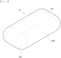
- FIG. 2 is a perspective view showing an outer appearance of the curve-combined polygonal pressure tank 10 according to the present invention.
- the curve-combined polygonal pressure tank 10 according to the present invention may include a pair of flat members 100, a plurality of first curved members 200 that connect facing edges of the pair of flat members 100, and a plurality of second curved members 300 that connect neighboring edges of the plurality of first curved members 200.
- a cylindrical pressure tank with an external curved surface may be maintained at predetermined internal pressure only by a thickness of the pressure tank without a special reinforcing structure therein, but the polygonal pressure tank has a limit in maintaining internal pressure only by the flat member 100 and, thus, the flat members 100 need to be connected by a tension member 400 such as a tension beam or a tension plate to satisfy pressure-resistant performance.
- a tension member 400 such as a tension beam or a tension plate to satisfy pressure-resistant performance.
- FIG. 4 illustrates a cross sectional shape of the curve-combined polygonal pressure tank 10 according to the present invention along the Y axis to overcome the above problem.
- a position of the outermost tension member 410 that is installed to be closest to the curved member 200 among the plurality of tension members 400 may be determined as a position spaced apart from the curved member by a constant distance toward the flat member 100, but not a boundary between the flat member 100 and the curved member and, thus, a stress-buffer portion for preventing stress discontinuity may be formed.
- FIG. 5 is a schematic diagram showing a principle for overcoming stress discontinuity, which corresponds to the first object of the present invention.
- a position of the outermost tension member 410 that is installed to be closest to the curved member 200 among the plurality of tension members 400 may be determined as a position spaced apart from the curved member by a constant distance toward the flat member, but not a boundary between the flat member 100 and the curved member and, thus, stress discontinuity generated at the boundary between the flat member 100 and the curved member 200 may be reduced.
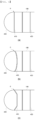
- FIG. 6 is a schematic diagram showing Embodiment 1-1 and modified embodiments thereof for the first object of the present invention in the curve-combined polygonal pressure tank 10 according to the present invention.
- the outermost tension member 410 may be disposed at a connection portion between the flat member 100 and the curved member and the outermost tension member 410 may have a smaller thickness than that of the other tension members 400 disposed inside the polygonal pressure tank 10, thereby achieving a stress balancing effect that is similar to the case in which a stress-buffer portion with a predetermined region is formed at an end portion of the flat member 100.
- FIG. 6 is a schematic diagram showing Embodiment 1-1 and modified embodiments thereof for the first object of the present invention in the curve-combined polygonal pressure tank 10 according to the present invention.
- the outermost tension member 410 may be disposed at a connection portion between the flat member 100 and the curved member and the outermost tension member 410 may have a smaller thickness than that of the other tension members 400 disposed inside the
- the outermost tension member 410 may be curved in an opposite direction to the curved member 200 and, as shown in FIG. 6C , the outermost tension member 410 may be formed like a 'U' shape or an angular 'U' shape with a curved portion.
- FIG. 7 is a schematic diagram showing Embodiment 1-2 and modified embodiments thereof for the first object of the present invention in the curve-combined polygonal pressure tank 10 and, here, a connection reinforcing member 500 for connection between the outermost tension member 410 and the curved member 200 is added.
- the connection reinforcing member 500 may be shaped like an arced connection reinforcing member 510 that is formed at only a portion of the curved member 200 as shown in FIG. 7A , or a circular connection reinforcing member 520 that is formed at an entire portion of the curved member 200 as shown in FIG. 7B and, in this case, the connection reinforcing member 500 may be shaped like the circular connection reinforcing member 520 that is thinned toward a central portion of a curved portion as shown in FIG. 7C .
- FIG. 8 is a schematic diagram showing Embodiment 1-3 and modified embodiments thereof for the first object of the present invention in the curve-combined polygonal pressure tank 10.
- the circular connection reinforcing member 520 may be thickened toward a central portion of the curved portion as shown in FIG. 8B and, as another modified embodiment, the separate circular connection reinforcing member 520 may be formed only at the central portion of the curved portion as shown in FIG. 8C .
- an end of the curved member 200, adjacent to the outermost tension member 410, and the outermost tension member 410 may be a portion BW that is vulnerable with respect to buckling.
- FIGS. 10 and 11 are schematic diagrams showing an embodiment and a modified embodiment for the second object of the present invention in the curve-combined polygonal pressure tank 10 according to the present invention and, here, as a method of overcoming the second object, according to the present invention, a reinforcing member may be added to a lateral surface of a tension beam that is an example of the tension member 400.
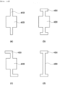
- FIG. 10 is a diagram showing an embodiment and a modified embodiment of a cross sectional shape of a tension beam for preventing buckling.
- 1-shape reinforcing members 450 shown in FIG. 10A , T-shape reinforcing members 450 shown in FIG. 10B , or L-shape reinforcing members 450 shown in FIG. 10C may be added to facing lateral surfaces of the tension beam, or the tension beam may be formed with a H-shape sectional view as shown in FIG. 10D .
- the shape of the tension beam reinforcing member 450 is not limited to the above embodiments and may be modified in various ways.
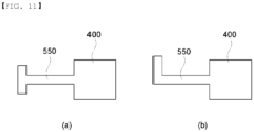
- FIG. 11 is a diagram showing an embodiment and a modified embodiment of a cross sectional shape of the connection reinforcing member 500 for preventing buckling.
- the connection reinforcing member 500 may be formed with a T-shape sectional view or, as shown in FIG. 11B , may be formed with an L-shape sectional view.
- the cross sectional shape of the connection reinforcing member 500 for preventing buckling is not limited to the above embodiment and may be modified in various ways.
- the curve-combined polygonal pressure tank according to the present invention may be configured in such a way that discontinuity of internal pressure is overcome by thinning the tension member 400 to overcome a problem in terms of tension stress and, simultaneously, section modulus is increased by forming a reinforcing member in the tension beam to simultaneously overcome a problem in terms of compression stress.
- FIG. 12 shows a curve-combined polygonal pressure tank including a tension plate formed therein instead of a tension beam, as an example of the tension member 400 and, here, similarly to a curve-combined polygonal pressure tank including a tension beam formed therein, the outermost pressure plate may be spaced apart from a connection point between the flat member 100 and the curved member 200 by a constant distance d toward the flat member 100.
- Hollow portions 430 may be formed in the tension plate, liquefied natural gas (LNG) may be moved in the tank through the hollow portions 430 and, during manufacture of the tank, the hollow portions 430 may function as a path through which a worker moves.
- LNG liquefied natural gas
- the aforementioned additional method for enhancing the effect of preventing discontinuity of internal pressure may also be applied to the outermost tension plate and, as shown in FIG. 6 , the outermost tension plate may be thinned or may be formed with a curved shape or a U-shape.
- connection reinforcing member 500 for connection between the outermost tension plate and a portion of the curved member may be added and, as shown in Fig. 7 , the connection reinforcing member 500 may be shaped like an arced connection reinforcing member that is formed at only a portion of the curved member or a circular connection reinforcing member that is formed at an entire portion of the curved member, or the connection reinforcing member 500 may be thinned toward a central portion of the curved portion.
- the aforementioned additional method for preventing buckling may also be applied to the outermost tension plate and, as shown in FIGS. 10 and 11 , a reinforcing member with various cross sectional shapes may be added to the outermost tension plate and the connection reinforcing member 500 to enhance the effect of preventing buckling.
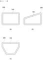
- the curve-combined polygonal pressure tank 10 according to the present invention may be formed with various shapes and, referring to FIG. 13 , a shape of the curve-combined polygonal pressure tank 10 according to the present invention viewed in the Z-axis direction, that is, a shape of the flat member 100 viewed from an upper portion thereof may be a flat rectangular shape as shown in FIG. 13A but may be an asymmetrical shape with different facing surfaces depending on a shape of a space for cumulating pressure tanks and, for example, may be a trapezoidal shape as shown in FIG. 13B , or may be a polygonal shape with one narrow side as shown in FIG. 13C , or may have another polygonal shape.
- FIG. 14 shows the embodiment shown in FIG. 13C in a 3D shape to aid in understanding and, here, one side with a narrow width is disposed toward a stem or a stern or is disposed downward depending on a shape of a vessel, thereby enhancing space efficiency. That is, the flat member 100 may have a polygonal shape and may be formed in such a way that one of the facing sides is shorter than the other side.
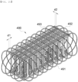
- FIGS. 15 to 17 are shown for explanation of a structure of an internal grid structure 490 of the embodiment of FIG. 13C and, here, the internal grid structure 490 may include a grid reinforcing member 460 that is formed in grid patterns by arranging a plurality of H-type beams perpendicularly to each other between the flat members 100, and a plurality of ring-type reinforcing members 470 that extend from a portion of the H-type beams and are coupled to an internal side of the adjacent first curved member 200, with predetermined curvature.
- a grid reinforcing member 460 that is formed in grid patterns by arranging a plurality of H-type beams perpendicularly to each other between the flat members 100, and a plurality of ring-type reinforcing members 470 that extend from a portion of the H-type beams and are coupled to an internal side of the adjacent first curved member 200, with predetermined curvature.
- the outermost H-type beam among the plurality of H-type beams may be disposed in the tank to be spaced apart from an edge connected between the flat member 100 and the first curved member 200 by a constant distance and some of the plurality of ring-type reinforcing members 470 may have a T-shape sectional view.
- FIGS. 18 and 19 show a curve-combined polygonal pressure tank with a tension plate formed therein according to a third embodiment and, according to the third embodiment, a grid-type reinforcing structure 480 may be formed between the flat members 100 and may include flat plate-type reinforcing members 481 having the hollow portions 430 and linear-type reinforcing members 482 for connecting the flat plate-type reinforcing members 481.
- a reinforcing flange 431 may be formed on an outer periphery of the hollow portion 430.
- a distance by which the outermost member is spaced apart from a boundary between the flat member 100 and the curved member 200 may be configured with different distances d1 and d2 in width and length directions, respectively.
- FIGS. 20 to 22 show a modified embodiment of the third embodiment of the curve-combined polygonal pressure tank that additionally includes the reinforcing ring.
- the reinforcing ring additionally included inside the curved member may also be applied to the aforementioned curve-combined polygonal pressure tank with the tension beam therein as shown in FIG. 19 .
- a plurality of horizontal grid plates 491 and a plurality of vertical grid plates 492, each of which includes a reinforcing ring formed therein, may cross each other and, as necessary, a plurality of linear-type reinforcing members 493 may be disposed between the horizontal grid plates 491 or the vertical grid plates 492 to reinforce strength.
- a distance by which the outermost member is spaced apart from a boundary between the flat member 100 and the curved member 200 may be configured with different distances d1 and d2 in width and length directions, respectively.
- FIG. 22 shows the curve-combined polygonal pressure tank 10 according to another embodiment and shows an embodiment of two pairs of flat members 100, but not a pair of flat members.
- the curve-combined polygonal pressure tank 10 according to a fourth embodiment shown in FIG. 22 may be different from the aforementioned embodiment in that the fourth embodiment has the feature in which the number of curved surfaces except for edge portions is two.
- FIG. 24 shows an embodiment for overcoming the above problem and, here, cross frames 610 for connection between lateral end portions may each be disposed in up and down directions to achieve an effect of overcoming stress imbalance at the lateral end portion and enhancing pressure-resistant performance.
- FIG. 24A shows an arrangement viewed from the above and
- FIG. 24B shows an arrangement viewed from the lateral aspect.
- a plurality of parallel plates 620 may be stacked in up and down directions and opposite ends of the parallel plate 620 may extend up to the curved member to achieve an effect of overcoming stress imbalance at the lateral end portion and enhancing pressure-resistant performance.
- the parallel plate 620 may be formed with a uniform thickness perpendicularly to a lateral flat member and, may be formed to surround an internal portion of the curved member as shown in FIG. 25B or may be formed to surround only an edge of the curved member as shown in FIG. 25C .
Landscapes
- Engineering & Computer Science (AREA)
- Mechanical Engineering (AREA)
- Chemical & Material Sciences (AREA)
- Combustion & Propulsion (AREA)
- Ocean & Marine Engineering (AREA)
- General Engineering & Computer Science (AREA)
- Life Sciences & Earth Sciences (AREA)
- Sustainable Development (AREA)
- Sustainable Energy (AREA)
- Transportation (AREA)
- Filling Or Discharging Of Gas Storage Vessels (AREA)
- Cooling, Air Intake And Gas Exhaust, And Fuel Tank Arrangements In Propulsion Units (AREA)
Claims (14)
- Kurvenkombinierter polygonaler Druckbehälter (10) zur Aufnahme eines Fluids unter hohem Druck in seinem Innern, wobei der Druckbehälter (10) aufweist:flache Elemente (100), die am oberen und unteren Abschnitt des Druckbehälters (10) angeordnet sind;ein erstes gekrümmtes Element (200), das die Kanten des am oberen Abschnitt angeordneten flachen Elements und des am unteren Abschnitt angeordneten flachen Elements verbindet und mit einer vorgegebenen Krümmung ausgebildet ist; undein zweites gekrümmtes Element (300), das benachbarte gekrümmte Kanten des ersten gekrümmten Elements verbindet,wobei der kurvenkombinierte polygonale Druckbehälter (10) einen darin ausgebildeten Spannungspufferabschnitt aufweist, um eine Spannungsdiskontinuität an einem Verbindungsabschnitt zwischen dem flachen Element (100) und dem ersten gekrümmten Element (200) zu verhindern,wobei der kurvenkombinierte polygonale Druckbehälter (10) eine Vielzahl von Zugelementen (400) aufweist, die zwischen dem flachen Element (100), das am oberen Abschnitt angeordnet ist, und dem flachen Element (100), das am unteren Abschnitt angeordnet ist, angeordnet sind; undwobei das äußerste Zugelement (410) unter der Vielzahl von Zugelementen (400) von einer Grenze (P), an der das erste gekrümmte Element (200) und das flache Element (100) einander berühren, um einen konstanten Abstand (d) in Richtung des flachen Elements (100) beabstandet ist, um den Spannungspufferabschnitt zu bilden, oderwobei das äußerste Zugelement (410) unter der Vielzahl von Zugelementen (400) an eine Grenze (P) gekoppelt ist, an der das erste gekrümmte Element (200) und das flache Element (100) einander berühren, und ausgebildet ist, um dünner zu sein als ein Zugelement, das einwärts angeordnet ist, um den Spannungspufferabschnitt zu bilden, oderwobei das äußerste Zugelement (410) unter der Vielzahl von Zugelementen (400) an eine Grenze (P) gekoppelt ist, an der das erste gekrümmte Element (200) und das flache Element (100) einander berühren, und mit einer vorgegebenen Krümmung in einer dem ersten gekrümmten Element (200) entgegengesetzten Richtung gekrümmt ist oder mit einem gebogenen Abschnitt ausgebildet ist, der in einer dem ersten gekrümmten Element (200) entgegengesetzten Richtung gebogen ist, um einen Spannungspufferabschnitt zu bilden.
- Kurvenkombinierter polygonaler Druckbehälter nach Anspruch 1, wobei das äußerste Zugelement (410) unter der Vielzahl von Zugelementen (400) ein Verbindungsverstärkungselement (500) aufweist, das sich zu dem ersten gekrümmten Element (200) erstreckt.
- Kurvenkombinierter polygonaler Druckbehälter nach Anspruch 2, wobei das Verbindungsverstärkungselement (500) ein Ende hat, das das äußerste Zugelement (410) berührt, und das andere Ende, das sich zu einem gekrümmten Abschnitt des ersten gekrümmten Elements (200) erstreckt, und/oder
wobei das Verbindungsverstärkungselement (500) ein T-förmiges oder L-förmiges Verstärkungselement ist. - Kurvenkombinierter polygonaler Druckbehälter nach Anspruch 3, wobei das Verbindungsverstärkungselement (500) ein kreisförmiges Verbindungsverstärkungselement (520) ist, das entlang einer gekrümmten Oberfläche des ersten gekrümmten Elements (200) ausgebildet ist.
- Kurvenkombinierter polygonaler Druckbehälter nach Anspruch 4, wobei das kreisförmige Verbindungsverstärkungselement (520) des Verbindungsverstärkungselements eine Höhe aufweist, die in Richtung der Mitte des ersten gekrümmten Elements (200) abnimmt.
- Kurvenkombinierter polygonaler Druckbehälter nach Anspruch 1, wobei das erste gekrümmte Element (200) einen größeren Krümmungsradius aufweist als die Hälfte des Abstands zwischen dem flachen Element, das am oberen Abschnitt angeordnet ist, und dem flachen Element, das am unteren Abschnitt angeordnet ist.
- Kurvenkombinierter polygonaler Druckbehälter nach Anspruch 6, wobei in der Mitte des ersten gekrümmten Elements (200) ein kreisförmiges Verbindungsverstärkungselement (520) ausgebildet ist.
- Kurvenkombinierter polygonaler Druckbehälter nach Anspruch 2, wobei das Zugelement (400) ein Zugträger, eine Zuglasche oder eine Kombination davon ist, und/oder
wobei eine Seitenfläche des Zugelements (400) um ein Verstärkungselement (450 ergänzt ist. - Kurvenkombinierter polygonaler Druckbehälter nach Anspruch 8, wobei das Verstärkungselement (450), um das die Seitenfläche des Zugelements (400) ergänzt ist, ein 1-förmiges, T-förmiges oder L-förmiges Verstärkungselement ist.
- Kurvenkombinierter polygonaler Druckbehälter nach Anspruch 1, wobei das flache Element (100) von seinem oberen Abschnitt aus gesehen eine rechteckige Form, eine asymmetrische Form mit unterschiedlichen zugewandten Oberflächen, eine Trapezform oder eine polygonale Form mit einer kürzeren Seite als die andere Seite der entsprechenden einander zugewandten Seiten aufweist.
- Kurvenkombinierter polygonaler Druckbehälter nach Anspruch 10, wobei der kurvenkombinierte polygonale Druckbehälter eine darin ausgebildete innere Gitterstruktur (490) aufweist, die ein Gitterverstärkungselement (460), das in Gittermustern durch Anordnen einer Vielzahl von Trägern senkrecht zueinander zwischen den flachen Elementen (100) ausgebildet ist, und eine Vielzahl ringartiger Verstärkungselemente (470) aufweist, die sich von einem Abschnitt der Vielzahl von Trägern erstrecken und mit einer Innenseite des angrenzenden ersten gekrümmten Elements (200) mit einer vorgegebenen Krümmung verbunden sind.
- Kurvenkombinierter polygonaler Druckbehälter nach Anspruch 11, wobei der äußerste Balken aus der Vielzahl von Balken von einer mit dem flachen Element (100) und dem ersten gekrümmten Element (200) verbundenen Kante um einen konstanten Abstand beabstandet und einwärts angeordnet ist.
- Kurvenkombinierter polygonaler Druckbehälter nach Anspruch 11 oder Anspruch 12, wobei die Vielzahl von Trägern eine H-förmige Schnittansicht hat.
- Kurvenkombinierter polygonaler Druckbehälter nach Anspruch 13, wobei einige der Vielzahl ringartiger Verstärkungselemente (470) eine T-förmige Schnittansicht haben.
Applications Claiming Priority (2)
| Application Number | Priority Date | Filing Date | Title |
|---|---|---|---|
| KR20160023008 | 2016-02-26 | ||
| PCT/KR2017/002153 WO2017146551A1 (ko) | 2016-02-26 | 2017-02-27 | 곡면 조합 각형 압력탱크 |
Publications (4)
| Publication Number | Publication Date |
|---|---|
| EP3421863A1 EP3421863A1 (de) | 2019-01-02 |
| EP3421863A4 EP3421863A4 (de) | 2019-11-06 |
| EP3421863C0 EP3421863C0 (de) | 2024-10-02 |
| EP3421863B1 true EP3421863B1 (de) | 2024-10-02 |
Family
ID=59686415
Family Applications (1)
| Application Number | Title | Priority Date | Filing Date |
|---|---|---|---|
| EP17756888.8A Active EP3421863B1 (de) | 2016-02-26 | 2017-02-27 | Kurvenkombinierter quadratischer drucktank |
Country Status (5)
| Country | Link |
|---|---|
| US (3) | US10543745B2 (de) |
| EP (1) | EP3421863B1 (de) |
| CN (1) | CN109073150B (de) |
| SG (1) | SG11201808282YA (de) |
| WO (1) | WO2017146551A1 (de) |
Families Citing this family (11)
| Publication number | Priority date | Publication date | Assignee | Title |
|---|---|---|---|---|
| EP3421863B1 (de) | 2016-02-26 | 2024-10-02 | Latticetechnology Co., Ltd. | Kurvenkombinierter quadratischer drucktank |
| CN109780434B (zh) * | 2018-12-29 | 2021-06-01 | 有研工程技术研究院有限公司 | 一种带应力缓冲结构的金属氢化物储氢罐 |
| DE102019115018A1 (de) | 2019-06-04 | 2020-12-10 | Tge Marine Gas Engineering Gmbh | Tankanordnung |
| WO2021064694A1 (en) * | 2019-10-04 | 2021-04-08 | Tyco Fire Products Lp | Fire suppression systems including modular storage tanks |
| CN112664821A (zh) * | 2021-01-11 | 2021-04-16 | 上海船舶研究设计院(中国船舶工业集团公司第六0四研究院) | 扁平型压力容器 |
| CN112762349A (zh) * | 2021-01-12 | 2021-05-07 | 上海船舶研究设计院(中国船舶工业集团公司第六0四研究院) | 带拉力杆的一体式扁平型压力容器阵列罐 |
| CN113217803A (zh) * | 2021-01-12 | 2021-08-06 | 上海船舶研究设计院(中国船舶工业集团公司第六0四研究院) | 带拉力杆的扁平型压力容器 |
| CN112797308B (zh) * | 2021-01-15 | 2025-09-02 | 上海船舶研究设计院(中国船舶工业集团公司第六0四研究院) | Lng储存罐及lng储存罐组合设备 |
| NO348049B1 (en) * | 2021-02-22 | 2024-07-08 | Lattice Int As | Cellular pressure vessel, method for fabrication and use thereof |
| IT202200005474A1 (it) * | 2022-03-21 | 2023-09-21 | Agt S R L | Serbatoio per gas in pressione. |
| CN115930089A (zh) * | 2023-01-10 | 2023-04-07 | 南京工业大学 | 一种气体存储用保形储罐 |
Citations (3)
| Publication number | Priority date | Publication date | Assignee | Title |
|---|---|---|---|---|
| US20090145909A1 (en) * | 2006-04-21 | 2009-06-11 | Magna Steyr Fahrzeugtechnik Ag & Co. Kg | Inner container surrounded by an outer container, used for receiving a cryogenic liquid |
| KR20110132657A (ko) * | 2010-06-03 | 2011-12-09 | 현대중공업 주식회사 | 충격흡수 및 단열 패널을 구비한 독립형 액화가스 화물창 |
| US20140166664A1 (en) * | 2012-12-17 | 2014-06-19 | The Curators Of The University Of Missouri | Conformal Tank For Adsorbant Natural Gas Storage |
Family Cites Families (20)
| Publication number | Priority date | Publication date | Assignee | Title |
|---|---|---|---|---|
| US3441164A (en) * | 1966-08-24 | 1969-04-29 | Union Carbide Corp | Cryogenic storage tanks |
| DE2931947A1 (de) * | 1979-08-07 | 1981-02-26 | Juergens Walter | Gasbehaeltnis |
| JPS59137663A (ja) * | 1983-01-27 | 1984-08-07 | Kawasaki Heavy Ind Ltd | 構造不連続中和領域を有する多層巻圧力容器 |
| DE19749950C2 (de) | 1997-11-03 | 1999-11-25 | Mannesmann Ag | Behälter zum Speichern von Druckgas |
| US6732881B1 (en) | 1998-10-15 | 2004-05-11 | Mobil Oil Corporation | Liquefied gas storage tank |
| DE19855969A1 (de) | 1998-12-04 | 2000-06-21 | Progress Werk Oberkirch Ag | Druckbehälter |
| DE19929421B4 (de) * | 1999-06-26 | 2015-05-13 | Bayerische Motoren Werke Aktiengesellschaft | Behälter zur Aufnahme von Fluiden |
| US6364099B2 (en) | 1999-12-21 | 2002-04-02 | Michael J. Emoff | Coupon dispenser assembly and shroud |
| DE10008985A1 (de) * | 2000-02-25 | 2001-08-30 | Linde Ag | Speicherbehälter |
| FR2843441B1 (fr) * | 2002-08-09 | 2004-11-19 | Suder | Reservoir metallique pour gaz liquefie sous pression |
| DE10329990B3 (de) * | 2003-07-02 | 2005-04-21 | Benteler Automobiltechnik Gmbh | Druckgastank |
| NO20042678D0 (no) | 2004-06-25 | 2004-06-25 | Det Norske Veritas As | Tank for storage of fluids at low temperatures, support means for a tank, sandwich structure for use in a tank and method for manufacturing a tank |
| AT8860U1 (de) * | 2005-04-13 | 2007-01-15 | Magna Steyr Fahrzeugtechnik Ag | Modularer behälter für kryogene flüssigkeiten |
| KR100840032B1 (ko) * | 2007-05-18 | 2008-06-19 | 현대중공업 주식회사 | 다축 연장 구형탱크 |
| GB2466965A (en) | 2009-01-15 | 2010-07-21 | Cappelen Skovholt As | Liquefied gas storage tank with curved sidewall |
| BR112013027445B1 (pt) * | 2011-04-25 | 2021-08-03 | Korea Advanced Institute Of Science Adn Technology | Tanque de pressão tendo uma estrutura de treliça |
| CN203757362U (zh) | 2011-11-17 | 2014-08-06 | 现代重工业株式会社 | 压力容器用加强板以及包括其的液化气储存及运输用罐体 |
| US10279921B2 (en) | 2012-10-31 | 2019-05-07 | General Electric Company | Cryogenic tank |
| KR101615100B1 (ko) | 2014-11-19 | 2016-05-11 | 한국과학기술원 | 내부에 중공부를 갖는 격자형 압력탱크 |
| EP3421863B1 (de) * | 2016-02-26 | 2024-10-02 | Latticetechnology Co., Ltd. | Kurvenkombinierter quadratischer drucktank |
-
2017
- 2017-02-27 EP EP17756888.8A patent/EP3421863B1/de active Active
- 2017-02-27 CN CN201780026338.6A patent/CN109073150B/zh active Active
- 2017-02-27 SG SG11201808282YA patent/SG11201808282YA/en unknown
- 2017-02-27 WO PCT/KR2017/002153 patent/WO2017146551A1/ko not_active Ceased
- 2017-02-27 US US16/080,181 patent/US10543745B2/en active Active
-
2019
- 2019-12-09 US US16/707,687 patent/US11338667B2/en active Active
-
2022
- 2022-04-22 US US17/727,381 patent/US11731505B2/en active Active
Patent Citations (3)
| Publication number | Priority date | Publication date | Assignee | Title |
|---|---|---|---|---|
| US20090145909A1 (en) * | 2006-04-21 | 2009-06-11 | Magna Steyr Fahrzeugtechnik Ag & Co. Kg | Inner container surrounded by an outer container, used for receiving a cryogenic liquid |
| KR20110132657A (ko) * | 2010-06-03 | 2011-12-09 | 현대중공업 주식회사 | 충격흡수 및 단열 패널을 구비한 독립형 액화가스 화물창 |
| US20140166664A1 (en) * | 2012-12-17 | 2014-06-19 | The Curators Of The University Of Missouri | Conformal Tank For Adsorbant Natural Gas Storage |
Also Published As
| Publication number | Publication date |
|---|---|
| US10543745B2 (en) | 2020-01-28 |
| EP3421863C0 (de) | 2024-10-02 |
| US11338667B2 (en) | 2022-05-24 |
| US20220242225A1 (en) | 2022-08-04 |
| EP3421863A1 (de) | 2019-01-02 |
| CN109073150A (zh) | 2018-12-21 |
| US11731505B2 (en) | 2023-08-22 |
| SG11201808282YA (en) | 2018-10-30 |
| EP3421863A4 (de) | 2019-11-06 |
| US20200108712A1 (en) | 2020-04-09 |
| WO2017146551A1 (ko) | 2017-08-31 |
| CN109073150B (zh) | 2021-05-14 |
| US20190100099A1 (en) | 2019-04-04 |
Similar Documents
| Publication | Publication Date | Title |
|---|---|---|
| US11338667B2 (en) | Curve-combined square pressure tank | |
| KR102029864B1 (ko) | 강화 피스가 구비된 밀봉 단열 탱크 | |
| KR100667500B1 (ko) | 액화천연가스 저장탱크 및 그 제조용 모듈 | |
| JP6416768B2 (ja) | 直交する折り目による波状の金属製メンブレンを含む液密熱絶縁タンク | |
| EP3066380B1 (de) | Hochkonformer druckbehälter | |
| US12007073B2 (en) | Heat insulation structure for corner parts of liquefied natural gas storage tank | |
| CA2957403C (en) | Corner structure of lng storage tank | |
| KR101368763B1 (ko) | 액화천연가스 화물창의 단열구조 | |
| EP3090963A1 (de) | Flüssigkeitstank | |
| KR20130023120A (ko) | 압력 용기 | |
| US20220390069A1 (en) | Corner structure of liquefied gas storage tank | |
| KR101455637B1 (ko) | 액화천연가스 저장탱크의 단열구조 | |
| KR102192104B1 (ko) | 압력탱크 및 이를 구비하는 선박 | |
| KR101647459B1 (ko) | 극저온 유체 저장용 탱크의 멤브레인 | |
| KR101588661B1 (ko) | 화물창 및 이에 사용되는 방벽 보강부재 | |
| JP5750405B2 (ja) | 圧力容器 | |
| KR20180077568A (ko) | 독립형 lng 저장탱크 | |
| JP2017178367A (ja) | 液体貯蔵タンク | |
| KR102885979B1 (ko) | 액화가스 저장탱크 및 이를 포함하는 선박 | |
| KR101567860B1 (ko) | 진공단열패널을 구비한 단열 박스 및 이를 가지는 초저온 유체 화물창 | |
| KR102075970B1 (ko) | 주름 집중형 멤브레인 및 이를 이용한 극저온 유체 저장탱크 | |
| KR102160872B1 (ko) | 액화가스 저장탱크 및 이를 구비하는 선박 | |
| KR102213510B1 (ko) | Lng 저장탱크의 단열박스 | |
| KR20130064207A (ko) | 선박의 횡단구조 | |
| KR20250008596A (ko) | 극저온 저장탱크 멤브레인 |
Legal Events
| Date | Code | Title | Description |
|---|---|---|---|
| STAA | Information on the status of an ep patent application or granted ep patent |
Free format text: STATUS: THE INTERNATIONAL PUBLICATION HAS BEEN MADE |
|
| PUAI | Public reference made under article 153(3) epc to a published international application that has entered the european phase |
Free format text: ORIGINAL CODE: 0009012 |
|
| STAA | Information on the status of an ep patent application or granted ep patent |
Free format text: STATUS: REQUEST FOR EXAMINATION WAS MADE |
|
| 17P | Request for examination filed |
Effective date: 20180926 |
|
| AK | Designated contracting states |
Kind code of ref document: A1 Designated state(s): AL AT BE BG CH CY CZ DE DK EE ES FI FR GB GR HR HU IE IS IT LI LT LU LV MC MK MT NL NO PL PT RO RS SE SI SK SM TR |
|
| AX | Request for extension of the european patent |
Extension state: BA ME |
|
| DAV | Request for validation of the european patent (deleted) | ||
| DAX | Request for extension of the european patent (deleted) | ||
| A4 | Supplementary search report drawn up and despatched |
Effective date: 20191007 |
|
| RIC1 | Information provided on ipc code assigned before grant |
Ipc: F17C 3/00 20060101AFI20190930BHEP Ipc: B63B 17/00 20060101ALI20190930BHEP Ipc: B63B 25/16 20060101ALI20190930BHEP Ipc: F17C 13/00 20060101ALI20190930BHEP Ipc: B60K 15/03 20060101ALI20190930BHEP Ipc: B63B 11/04 20060101ALI20190930BHEP Ipc: F17C 1/08 20060101ALI20190930BHEP |
|
| RIN1 | Information on inventor provided before grant (corrected) |
Inventor name: PARK, HOON JIN Inventor name: JO, CHOONGHEE Inventor name: PARK, KEUN OH |
|
| STAA | Information on the status of an ep patent application or granted ep patent |
Free format text: STATUS: EXAMINATION IS IN PROGRESS |
|
| 17Q | First examination report despatched |
Effective date: 20220324 |
|
| GRAP | Despatch of communication of intention to grant a patent |
Free format text: ORIGINAL CODE: EPIDOSNIGR1 |
|
| STAA | Information on the status of an ep patent application or granted ep patent |
Free format text: STATUS: GRANT OF PATENT IS INTENDED |
|
| INTG | Intention to grant announced |
Effective date: 20240506 |
|
| RAP3 | Party data changed (applicant data changed or rights of an application transferred) |
Owner name: LATTICETECHNOLOGY CO., LTD. |
|
| GRAS | Grant fee paid |
Free format text: ORIGINAL CODE: EPIDOSNIGR3 |
|
| GRAA | (expected) grant |
Free format text: ORIGINAL CODE: 0009210 |
|
| STAA | Information on the status of an ep patent application or granted ep patent |
Free format text: STATUS: THE PATENT HAS BEEN GRANTED |
|
| AK | Designated contracting states |
Kind code of ref document: B1 Designated state(s): AL AT BE BG CH CY CZ DE DK EE ES FI FR GB GR HR HU IE IS IT LI LT LU LV MC MK MT NL NO PL PT RO RS SE SI SK SM TR |
|
| REG | Reference to a national code |
Ref country code: GB Ref legal event code: FG4D |
|
| REG | Reference to a national code |
Ref country code: CH Ref legal event code: EP |
|
| REG | Reference to a national code |
Ref country code: DE Ref legal event code: R096 Ref document number: 602017085217 Country of ref document: DE |
|
| REG | Reference to a national code |
Ref country code: IE Ref legal event code: FG4D |
|
| U01 | Request for unitary effect filed |
Effective date: 20241002 |
|
| U07 | Unitary effect registered |
Designated state(s): AT BE BG DE DK EE FI FR IT LT LU LV MT NL PT RO SE SI Effective date: 20241009 |
|
| U20 | Renewal fee for the european patent with unitary effect paid |
Year of fee payment: 9 Effective date: 20250221 |
|
| PG25 | Lapsed in a contracting state [announced via postgrant information from national office to epo] |
Ref country code: IS Free format text: LAPSE BECAUSE OF FAILURE TO SUBMIT A TRANSLATION OF THE DESCRIPTION OR TO PAY THE FEE WITHIN THE PRESCRIBED TIME-LIMIT Effective date: 20250202 Ref country code: HR Free format text: LAPSE BECAUSE OF FAILURE TO SUBMIT A TRANSLATION OF THE DESCRIPTION OR TO PAY THE FEE WITHIN THE PRESCRIBED TIME-LIMIT Effective date: 20241002 |
|
| PG25 | Lapsed in a contracting state [announced via postgrant information from national office to epo] |
Ref country code: ES Free format text: LAPSE BECAUSE OF FAILURE TO SUBMIT A TRANSLATION OF THE DESCRIPTION OR TO PAY THE FEE WITHIN THE PRESCRIBED TIME-LIMIT Effective date: 20241002 |
|
| PG25 | Lapsed in a contracting state [announced via postgrant information from national office to epo] |
Ref country code: NO Free format text: LAPSE BECAUSE OF FAILURE TO SUBMIT A TRANSLATION OF THE DESCRIPTION OR TO PAY THE FEE WITHIN THE PRESCRIBED TIME-LIMIT Effective date: 20250102 |
|
| PG25 | Lapsed in a contracting state [announced via postgrant information from national office to epo] |
Ref country code: GR Free format text: LAPSE BECAUSE OF FAILURE TO SUBMIT A TRANSLATION OF THE DESCRIPTION OR TO PAY THE FEE WITHIN THE PRESCRIBED TIME-LIMIT Effective date: 20250103 |
|
| PG25 | Lapsed in a contracting state [announced via postgrant information from national office to epo] |
Ref country code: PL Free format text: LAPSE BECAUSE OF FAILURE TO SUBMIT A TRANSLATION OF THE DESCRIPTION OR TO PAY THE FEE WITHIN THE PRESCRIBED TIME-LIMIT Effective date: 20241002 Ref country code: CZ Free format text: LAPSE BECAUSE OF FAILURE TO SUBMIT A TRANSLATION OF THE DESCRIPTION OR TO PAY THE FEE WITHIN THE PRESCRIBED TIME-LIMIT Effective date: 20241002 |
|
| PG25 | Lapsed in a contracting state [announced via postgrant information from national office to epo] |
Ref country code: RS Free format text: LAPSE BECAUSE OF FAILURE TO SUBMIT A TRANSLATION OF THE DESCRIPTION OR TO PAY THE FEE WITHIN THE PRESCRIBED TIME-LIMIT Effective date: 20250102 |
|
| PG25 | Lapsed in a contracting state [announced via postgrant information from national office to epo] |
Ref country code: SM Free format text: LAPSE BECAUSE OF FAILURE TO SUBMIT A TRANSLATION OF THE DESCRIPTION OR TO PAY THE FEE WITHIN THE PRESCRIBED TIME-LIMIT Effective date: 20241002 |
|
| PG25 | Lapsed in a contracting state [announced via postgrant information from national office to epo] |
Ref country code: SK Free format text: LAPSE BECAUSE OF FAILURE TO SUBMIT A TRANSLATION OF THE DESCRIPTION OR TO PAY THE FEE WITHIN THE PRESCRIBED TIME-LIMIT Effective date: 20241002 |
|
| PLBE | No opposition filed within time limit |
Free format text: ORIGINAL CODE: 0009261 |
|
| STAA | Information on the status of an ep patent application or granted ep patent |
Free format text: STATUS: NO OPPOSITION FILED WITHIN TIME LIMIT |
|
| 26N | No opposition filed |
Effective date: 20250703 |
|
| PG25 | Lapsed in a contracting state [announced via postgrant information from national office to epo] |
Ref country code: MC Free format text: LAPSE BECAUSE OF FAILURE TO SUBMIT A TRANSLATION OF THE DESCRIPTION OR TO PAY THE FEE WITHIN THE PRESCRIBED TIME-LIMIT Effective date: 20241002 |
|
| REG | Reference to a national code |
Ref country code: CH Ref legal event code: PL |
|
| PG25 | Lapsed in a contracting state [announced via postgrant information from national office to epo] |
Ref country code: CH Free format text: LAPSE BECAUSE OF NON-PAYMENT OF DUE FEES Effective date: 20250228 |
|
| GBPC | Gb: european patent ceased through non-payment of renewal fee |
Effective date: 20250227 |
|
| U1N | Appointed representative for the unitary patent procedure changed after the registration of the unitary effect |
Representative=s name: LORENZ SEIDLER GOSSEL PART. MBB; DE |
|
| PG25 | Lapsed in a contracting state [announced via postgrant information from national office to epo] |
Ref country code: GB Free format text: LAPSE BECAUSE OF NON-PAYMENT OF DUE FEES Effective date: 20250227 |
|
| PG25 | Lapsed in a contracting state [announced via postgrant information from national office to epo] |
Ref country code: IE Free format text: LAPSE BECAUSE OF NON-PAYMENT OF DUE FEES Effective date: 20250227 |
|
| U20 | Renewal fee for the european patent with unitary effect paid |
Year of fee payment: 10 Effective date: 20260223 |