EP3421865A1 - Expansionsturbine und hochdruckwasserstofffüllsystem vom verdichtertyp sowie steuerungsverfahren dafür - Google Patents
Expansionsturbine und hochdruckwasserstofffüllsystem vom verdichtertyp sowie steuerungsverfahren dafür Download PDFInfo
- Publication number
- EP3421865A1 EP3421865A1 EP17756210.5A EP17756210A EP3421865A1 EP 3421865 A1 EP3421865 A1 EP 3421865A1 EP 17756210 A EP17756210 A EP 17756210A EP 3421865 A1 EP3421865 A1 EP 3421865A1
- Authority
- EP
- European Patent Office
- Prior art keywords
- expansion turbine
- compressor
- hydrogen
- expansion
- hydrogen gas
- Prior art date
- Legal status (The legal status is an assumption and is not a legal conclusion. Google has not performed a legal analysis and makes no representation as to the accuracy of the status listed.)
- Withdrawn
Links
Images




Classifications
-
- F—MECHANICAL ENGINEERING; LIGHTING; HEATING; WEAPONS; BLASTING
- F17—STORING OR DISTRIBUTING GASES OR LIQUIDS
- F17C—VESSELS FOR CONTAINING OR STORING COMPRESSED, LIQUEFIED OR SOLIDIFIED GASES; FIXED-CAPACITY GAS-HOLDERS; FILLING VESSELS WITH, OR DISCHARGING FROM VESSELS, COMPRESSED, LIQUEFIED, OR SOLIDIFIED GASES
- F17C5/00—Methods or apparatus for filling containers with liquefied, solidified, or compressed gases under pressures
- F17C5/06—Methods or apparatus for filling containers with liquefied, solidified, or compressed gases under pressures for filling with compressed gases
-
- F—MECHANICAL ENGINEERING; LIGHTING; HEATING; WEAPONS; BLASTING
- F17—STORING OR DISTRIBUTING GASES OR LIQUIDS
- F17C—VESSELS FOR CONTAINING OR STORING COMPRESSED, LIQUEFIED OR SOLIDIFIED GASES; FIXED-CAPACITY GAS-HOLDERS; FILLING VESSELS WITH, OR DISCHARGING FROM VESSELS, COMPRESSED, LIQUEFIED, OR SOLIDIFIED GASES
- F17C5/00—Methods or apparatus for filling containers with liquefied, solidified, or compressed gases under pressures
- F17C5/002—Automated filling apparatus
- F17C5/007—Automated filling apparatus for individual gas tanks or containers, e.g. in vehicles
-
- F—MECHANICAL ENGINEERING; LIGHTING; HEATING; WEAPONS; BLASTING
- F04—POSITIVE - DISPLACEMENT MACHINES FOR LIQUIDS; PUMPS FOR LIQUIDS OR ELASTIC FLUIDS
- F04D—NON-POSITIVE-DISPLACEMENT PUMPS
- F04D17/00—Radial-flow pumps, e.g. centrifugal pumps; Helico-centrifugal pumps
- F04D17/08—Centrifugal pumps
- F04D17/10—Centrifugal pumps for compressing or evacuating
-
- F—MECHANICAL ENGINEERING; LIGHTING; HEATING; WEAPONS; BLASTING
- F04—POSITIVE - DISPLACEMENT MACHINES FOR LIQUIDS; PUMPS FOR LIQUIDS OR ELASTIC FLUIDS
- F04D—NON-POSITIVE-DISPLACEMENT PUMPS
- F04D29/00—Details, component parts, or accessories
- F04D29/04—Shafts or bearings, or assemblies thereof
- F04D29/046—Bearings
-
- F—MECHANICAL ENGINEERING; LIGHTING; HEATING; WEAPONS; BLASTING
- F17—STORING OR DISTRIBUTING GASES OR LIQUIDS
- F17C—VESSELS FOR CONTAINING OR STORING COMPRESSED, LIQUEFIED OR SOLIDIFIED GASES; FIXED-CAPACITY GAS-HOLDERS; FILLING VESSELS WITH, OR DISCHARGING FROM VESSELS, COMPRESSED, LIQUEFIED, OR SOLIDIFIED GASES
- F17C13/00—Details of vessels or of the filling or discharging of vessels
- F17C13/02—Special adaptations of indicating, measuring, or monitoring equipment
- F17C13/026—Special adaptations of indicating, measuring, or monitoring equipment having the temperature as the parameter
-
- F—MECHANICAL ENGINEERING; LIGHTING; HEATING; WEAPONS; BLASTING
- F17—STORING OR DISTRIBUTING GASES OR LIQUIDS
- F17C—VESSELS FOR CONTAINING OR STORING COMPRESSED, LIQUEFIED OR SOLIDIFIED GASES; FIXED-CAPACITY GAS-HOLDERS; FILLING VESSELS WITH, OR DISCHARGING FROM VESSELS, COMPRESSED, LIQUEFIED, OR SOLIDIFIED GASES
- F17C2205/00—Vessel construction, in particular mounting arrangements, attachments or identifications means
- F17C2205/01—Mounting arrangements
- F17C2205/0123—Mounting arrangements characterised by number of vessels
- F17C2205/013—Two or more vessels
- F17C2205/0134—Two or more vessels characterised by the presence of fluid connection between vessels
- F17C2205/0142—Two or more vessels characterised by the presence of fluid connection between vessels bundled in parallel
-
- F—MECHANICAL ENGINEERING; LIGHTING; HEATING; WEAPONS; BLASTING
- F17—STORING OR DISTRIBUTING GASES OR LIQUIDS
- F17C—VESSELS FOR CONTAINING OR STORING COMPRESSED, LIQUEFIED OR SOLIDIFIED GASES; FIXED-CAPACITY GAS-HOLDERS; FILLING VESSELS WITH, OR DISCHARGING FROM VESSELS, COMPRESSED, LIQUEFIED, OR SOLIDIFIED GASES
- F17C2221/00—Handled fluid, in particular type of fluid
- F17C2221/01—Pure fluids
- F17C2221/012—Hydrogen
-
- F—MECHANICAL ENGINEERING; LIGHTING; HEATING; WEAPONS; BLASTING
- F17—STORING OR DISTRIBUTING GASES OR LIQUIDS
- F17C—VESSELS FOR CONTAINING OR STORING COMPRESSED, LIQUEFIED OR SOLIDIFIED GASES; FIXED-CAPACITY GAS-HOLDERS; FILLING VESSELS WITH, OR DISCHARGING FROM VESSELS, COMPRESSED, LIQUEFIED, OR SOLIDIFIED GASES
- F17C2223/00—Handled fluid before transfer, i.e. state of fluid when stored in the vessel or before transfer from the vessel
- F17C2223/01—Handled fluid before transfer, i.e. state of fluid when stored in the vessel or before transfer from the vessel characterised by the phase
- F17C2223/0107—Single phase
- F17C2223/0123—Single phase gaseous, e.g. CNG, GNC
-
- F—MECHANICAL ENGINEERING; LIGHTING; HEATING; WEAPONS; BLASTING
- F17—STORING OR DISTRIBUTING GASES OR LIQUIDS
- F17C—VESSELS FOR CONTAINING OR STORING COMPRESSED, LIQUEFIED OR SOLIDIFIED GASES; FIXED-CAPACITY GAS-HOLDERS; FILLING VESSELS WITH, OR DISCHARGING FROM VESSELS, COMPRESSED, LIQUEFIED, OR SOLIDIFIED GASES
- F17C2223/00—Handled fluid before transfer, i.e. state of fluid when stored in the vessel or before transfer from the vessel
- F17C2223/03—Handled fluid before transfer, i.e. state of fluid when stored in the vessel or before transfer from the vessel characterised by the pressure level
- F17C2223/036—Very high pressure (>80 bar)
-
- F—MECHANICAL ENGINEERING; LIGHTING; HEATING; WEAPONS; BLASTING
- F17—STORING OR DISTRIBUTING GASES OR LIQUIDS
- F17C—VESSELS FOR CONTAINING OR STORING COMPRESSED, LIQUEFIED OR SOLIDIFIED GASES; FIXED-CAPACITY GAS-HOLDERS; FILLING VESSELS WITH, OR DISCHARGING FROM VESSELS, COMPRESSED, LIQUEFIED, OR SOLIDIFIED GASES
- F17C2225/00—Handled fluid after transfer, i.e. state of fluid after transfer from the vessel
- F17C2225/01—Handled fluid after transfer, i.e. state of fluid after transfer from the vessel characterised by the phase
- F17C2225/0107—Single phase
- F17C2225/0123—Single phase gaseous, e.g. CNG, GNC
-
- F—MECHANICAL ENGINEERING; LIGHTING; HEATING; WEAPONS; BLASTING
- F17—STORING OR DISTRIBUTING GASES OR LIQUIDS
- F17C—VESSELS FOR CONTAINING OR STORING COMPRESSED, LIQUEFIED OR SOLIDIFIED GASES; FIXED-CAPACITY GAS-HOLDERS; FILLING VESSELS WITH, OR DISCHARGING FROM VESSELS, COMPRESSED, LIQUEFIED, OR SOLIDIFIED GASES
- F17C2225/00—Handled fluid after transfer, i.e. state of fluid after transfer from the vessel
- F17C2225/03—Handled fluid after transfer, i.e. state of fluid after transfer from the vessel characterised by the pressure level
- F17C2225/036—Very high pressure, i.e. above 80 bars
-
- F—MECHANICAL ENGINEERING; LIGHTING; HEATING; WEAPONS; BLASTING
- F17—STORING OR DISTRIBUTING GASES OR LIQUIDS
- F17C—VESSELS FOR CONTAINING OR STORING COMPRESSED, LIQUEFIED OR SOLIDIFIED GASES; FIXED-CAPACITY GAS-HOLDERS; FILLING VESSELS WITH, OR DISCHARGING FROM VESSELS, COMPRESSED, LIQUEFIED, OR SOLIDIFIED GASES
- F17C2227/00—Transfer of fluids, i.e. method or means for transferring the fluid; Heat exchange with the fluid
- F17C2227/01—Propulsion of the fluid
- F17C2227/0128—Propulsion of the fluid with pumps or compressors
- F17C2227/0157—Compressors
- F17C2227/0164—Compressors with specified compressor type, e.g. piston or impulsive type
-
- F—MECHANICAL ENGINEERING; LIGHTING; HEATING; WEAPONS; BLASTING
- F17—STORING OR DISTRIBUTING GASES OR LIQUIDS
- F17C—VESSELS FOR CONTAINING OR STORING COMPRESSED, LIQUEFIED OR SOLIDIFIED GASES; FIXED-CAPACITY GAS-HOLDERS; FILLING VESSELS WITH, OR DISCHARGING FROM VESSELS, COMPRESSED, LIQUEFIED, OR SOLIDIFIED GASES
- F17C2227/00—Transfer of fluids, i.e. method or means for transferring the fluid; Heat exchange with the fluid
- F17C2227/01—Propulsion of the fluid
- F17C2227/0128—Propulsion of the fluid with pumps or compressors
- F17C2227/0171—Arrangement
- F17C2227/0185—Arrangement comprising several pumps or compressors
-
- F—MECHANICAL ENGINEERING; LIGHTING; HEATING; WEAPONS; BLASTING
- F17—STORING OR DISTRIBUTING GASES OR LIQUIDS
- F17C—VESSELS FOR CONTAINING OR STORING COMPRESSED, LIQUEFIED OR SOLIDIFIED GASES; FIXED-CAPACITY GAS-HOLDERS; FILLING VESSELS WITH, OR DISCHARGING FROM VESSELS, COMPRESSED, LIQUEFIED, OR SOLIDIFIED GASES
- F17C2227/00—Transfer of fluids, i.e. method or means for transferring the fluid; Heat exchange with the fluid
- F17C2227/03—Heat exchange with the fluid
- F17C2227/0337—Heat exchange with the fluid by cooling
-
- F—MECHANICAL ENGINEERING; LIGHTING; HEATING; WEAPONS; BLASTING
- F17—STORING OR DISTRIBUTING GASES OR LIQUIDS
- F17C—VESSELS FOR CONTAINING OR STORING COMPRESSED, LIQUEFIED OR SOLIDIFIED GASES; FIXED-CAPACITY GAS-HOLDERS; FILLING VESSELS WITH, OR DISCHARGING FROM VESSELS, COMPRESSED, LIQUEFIED, OR SOLIDIFIED GASES
- F17C2260/00—Purposes of gas storage and gas handling
- F17C2260/02—Improving properties related to fluid or fluid transfer
- F17C2260/023—Avoiding overheating
-
- F—MECHANICAL ENGINEERING; LIGHTING; HEATING; WEAPONS; BLASTING
- F17—STORING OR DISTRIBUTING GASES OR LIQUIDS
- F17C—VESSELS FOR CONTAINING OR STORING COMPRESSED, LIQUEFIED OR SOLIDIFIED GASES; FIXED-CAPACITY GAS-HOLDERS; FILLING VESSELS WITH, OR DISCHARGING FROM VESSELS, COMPRESSED, LIQUEFIED, OR SOLIDIFIED GASES
- F17C2265/00—Effects achieved by gas storage or gas handling
- F17C2265/06—Fluid distribution
- F17C2265/065—Fluid distribution for refuelling vehicle fuel tanks
-
- F—MECHANICAL ENGINEERING; LIGHTING; HEATING; WEAPONS; BLASTING
- F17—STORING OR DISTRIBUTING GASES OR LIQUIDS
- F17C—VESSELS FOR CONTAINING OR STORING COMPRESSED, LIQUEFIED OR SOLIDIFIED GASES; FIXED-CAPACITY GAS-HOLDERS; FILLING VESSELS WITH, OR DISCHARGING FROM VESSELS, COMPRESSED, LIQUEFIED, OR SOLIDIFIED GASES
- F17C2270/00—Applications
- F17C2270/01—Applications for fluid transport or storage
- F17C2270/0165—Applications for fluid transport or storage on the road
- F17C2270/0184—Fuel cells
-
- Y—GENERAL TAGGING OF NEW TECHNOLOGICAL DEVELOPMENTS; GENERAL TAGGING OF CROSS-SECTIONAL TECHNOLOGIES SPANNING OVER SEVERAL SECTIONS OF THE IPC; TECHNICAL SUBJECTS COVERED BY FORMER USPC CROSS-REFERENCE ART COLLECTIONS [XRACs] AND DIGESTS
- Y02—TECHNOLOGIES OR APPLICATIONS FOR MITIGATION OR ADAPTATION AGAINST CLIMATE CHANGE
- Y02E—REDUCTION OF GREENHOUSE GAS [GHG] EMISSIONS, RELATED TO ENERGY GENERATION, TRANSMISSION OR DISTRIBUTION
- Y02E60/00—Enabling technologies; Technologies with a potential or indirect contribution to GHG emissions mitigation
- Y02E60/30—Hydrogen technology
- Y02E60/32—Hydrogen storage
Definitions
- This invention concerns the expansion turbine and compressor-type high-pressure hydrogen filling system and control method for same to be applied for temperature lowering system such as pre-cooler function at the final filling portion of the hydrogen filling equipment (hereinafter may be called “hydrogen station”)to fill the hydrogen gas to be the fuel for the hydrogen automobile such as fuel cell automobile (hereinafter may be just called “hydrogen automobile”) into the fuel tank of the hydrogen automobile from the hydrogen gas supply source.
- the hydrogen gas to be used as the fuel of the hydrogen automobile has such characteristic that if high pressure becomes adiabatic expansion (isenthalpic expansion) at such portion as expansion valve provided in the route to fill the hydrogen gas, it becomes the expansion in an area where the temperature is higher than the inversion point (-58C) because of its property, and due to the Joule Thomson effect, the temperature after the expansion rises.
- adiabatic expansion isenthalpic expansion
- the hydrogen gas to be the fuel of the hydrogen automobile is filled into the fuel tank of the hydrogen automobile from the hydrogen gas supply source at the hydrogen station, the temperature of the hydrogen gas rises at such a portion as expansion valve provided in the route to fill the hydrogen gas.
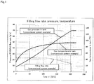
- Fig. 1 shows self-temperature changes at each secondary pressure when the hydrogen gas is expanded in one stage from the tank pressure of the supply source 70MPa(G), 30C.
- the highest temperature during hydrogen filling is limited to 85C due to the temperature restriction of the material of the fuel tank and restriction of operating temperature of the fuel cell itself.
- FIG. 2 shows the block diagram of presently ordinary hydrogen station of 70MPa (G) (source: "NEDO hydrogen energy white paper").
- This hydrogen station is equipped with compressor equipment 1 consisting of compressor unit to receive the hydrogen gas, hydrogen accumulating equipment 2 consisting of accumulator unit to accumulate the hydrogen gas sent from the compressor equipment 1, expansion valve 3 provided in the route to fill the hydrogen gas from the hydrogen accumulating equipment 2 into the fuel tank 6 of the hydrogen automobile, hydrogen pre-cooler 4, and hydrogen pre-cool system 5 to cool the hydrogen gas via the pre-cooler 4, and the hydrogen pre-cool system 5 is equipped with refrigerator equipment 7 consisting of compressor, condenser, expansion valve, evaporator and accumulator, and brine circuit system 8 consisting of brine tank, primary brine pump and secondary pump.
- the hydrogen received is compressed to the medium pressure (40MPa(G) in the illustration) and high pressure (82MPa (G) in the illustration) by the compressor equipment 1 and held in the form of compressed gas at each pressure in the compressor equipment 1.
- the expansion valve 3 In order to fill the hydrogen gas into the fuel tank 6 installed on the vehicle on the demand side, expansion is used via the expansion valve 3 but at that time, since it is accompanied by the temperature rise of the hydrogen gas itself, it is cooled to -40C by the hydrogen pre-cool system 5, outside equipment.
- the hydrogen pre-cool system 5 is composed of the combination of ordinary refrigerator equipment 7 such as CFC refrigerant and brine circuit 8 to operate at around 40C, and therefore, the composition is complicated, requiring many rotors including refrigerant compressor for refrigerator, primary brine pump and secondary brine pump.
- the hydrogen pre-cool station used to lower the temperature of hydrogen gas at the final filling portion of conventional hydrogen station involves the following problems.
- the hydrogen pre-cool system used for lowering the temperature of hydrogen gas at the final filling portion of the hydrogen station lowers the temperature of hydrogen gas by means of expansion equipment to take out the work in the process to expand and decompress the hydrogen gas and precools the hydrogen gas utilizing the cooling energy, and it can solve the problems of the hydrogen pre-cool system used to lower the temperature of the hydrogen gas at the final filling portion of the above conventional hydrogen station, but it had the following problem. 8) It is necessary to separately provide a means to take out and effectively use the energy produced in the expansion equipment.
- this invention has the object of providing the expansion turbine and compressor-type high-pressure hydrogen filling system and control method for same that can be applied for the temperature lowering system technology that has a simple composition, less burden of maintenance work, and less burden of maintenance work and capable of reducing the site work cost and also capable of reducing the operating cost including the cost of power consumption, and not necessary to separately provide a means to take out the energy produced in the expansion equipment and effectively use it outside for generator, for example.
- the expansion turbine/compressor type high-pressure hydrogen filling system of this invention is characterized in that the expansion turbine portion is equipped with a process to incorporate the expansion turbine/compressor in the filling system to do the enthalpy lowering of the hydrogen gas using the expansion turbine when the hydrogen gas accumulated at high pressure is pressurized and filled in the tank.
- the expansion turbine/compressor can be composed of an impeller to do expansion action on one side of the rotor shaft of the rotor and an impeller on the other side to do the compression action to consume the rotational energy obtained by the expansion.
- it can be equipped with bearings of a dynamic gas bearing system using the hydrogen gas supplied.
- it can be composed of one unit of expansion turbine/compressor.
- a cooler At the entrance portion on the expansion turbine side of the expansion turbine/compressor, a cooler can be provided.
- a cooler At the entrance portion on the compressor side of the expansion turbine/compressor, a cooler can be provided.
- control method of the expansion turbine/compressor-type high-pressure hydrogen filling system of this invention is characterized in that it is equipped with the process to incorporate the turbine/compressor in the expansion turbine portion in the control method of the filling system to do the enthalpy lowering of the hydrogen gas using the expansion turbine when the hydrogen gas accumulated at high pressure is filled into the tank, and a cooler installed at the entrance portion on the expansion turbine side, thus controlling the exit temperature of the hydrogen gas of the cooler.
- the exit temperature of the hydrogen gas of the aforementioned cooler can be detected and the cold energy amount of the cooler can be adjusted to follow so that the exit temperature will become a proper temperature.
- the expansion turbine/compressor type high-pressure hydrogen filling system of this invention when the hydrogen gas accumulated at high pressure is pressurized and filled into the tank, process is provided to incorporate the expansion turbine/compressor in the expansion turbine system to do the enthalpy lowering of the hydrogen gas using the expansion turbine and the hydrogen is finally expanded and the hydrogen gas with the enthalpy lowered (temperature lowered) is filled into the adjusting tank side, thus making it possible to provide the hydrogen pre-cool system to be used for lowering the temperature of the hydrogen gas in the final filling portion of the hydrogen station having a simple composition, less burden of maintenance work and capable of reducing the operating cost including the cost of power consumption.
- the expansion equipment or turbine to be used for this process inevitably becomes a very small and fast rotor if it is designed with the capacity to meet the present standard hydrogen filling plate (hydrogen station), and in case of a system to fill the high pressure hydrogen gas of say 5kg, the diameter of the expansion turbine will be 8 to 12mm and the number of revolutions at the maximum expansion ratio will be equivalent to 1.2 million resolutions/minute.
- the expansion turbine/compressor type high-pressure hydrogen of this invention is composed by providing an impeller (turbine) for expansion action on one side of the rotor shaft of the rotor and impeller (compressor) for compression action to consume the rotating energy obtained by expansion.
- the energy taken out by the expansion of the hydrogen gas by the turbine is taken out as kinetic energy in the form of high-speed rotation of the turbine rotor, and to realize this high-speed rotation, the expansion turbine/compressor adopts the bearing of dynamic gas bearing system using the hydrogen gas supplied. For this reason, the "work" taken out as the rotating energy can be such that the friction loss (shaft loss) due to the bearing is restricted to a very small value.
- the process gas pressure-raised on the compressor side is accompanied by pressure rise and temperature rise due to thermodynamic compression.
- the temperature rise is cooled to about 20C as required by providing a cooler (air cooling or water cooling after cooler) is discarded outside as heat. Since the pressure rise contributes to the pressure rise at the turbine entrance, it further increases the expansion ratio in the turbine, and as a result, it has the effect of increasing the cold generation.
- the technical reason to utilize the power taken out by the turbine within the process by adopting the turbine/compressor without converting to the electric power with the generator is not so established because the generator itself becomes small and high frequency for the equipment of small and high-speed rotation, and for the process gas in the relationship with hydrogen, superiority is cited from the viewpoint of explosion prevention.
- This expansion turbine/compressor type high-pressure hydrogen filling system has the expansion turbine/compressor type high-pressure hydrogen filling system of this invention applied for the hydrogen pre-cool system used to lower the temperature of the hydrogen gas at the final filling portion of the hydrogen station, and it is provided with a process to incorporate the expansion turbine/compressor in the expansion turbine portion in the filling system to do enthalpy lowering of the hydrogen gas using the expansion turbine when the hydrogen gas accumulated at high pressure is pressurized and filled in the tank.
- expansion turbine/compressor generally used for compression and expansion of refrigerant (called “expansion turbine/compressor” in this specification) having an impeller for expansion on one side of the rotating shaft and impeller for compression on the other side.
- This expansion turbine/compressor can be provided with bearings (bearings to support both radial and thrust directions) of dynamic gas bearing system using the hydrogen gas supplied.
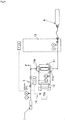
- this hydrogen pre-cool system 10 has the hydrogen gas source line 9 connected to the circuit of the expansion turbine/compressor and the hydrogen gas subjected to enthalpy lowering (temperature lowering) is finally expanded by the expansion turbine/compressor 11 and filled in the fuel tank of a hydrogen automobile via the hydrogen gas supply unit 13.
- the expansion turbine/compressor 11 is provided with the expansion turbine 11a having the impeller for expansion on one side of the rotating shaft and compressor 11b having the impeller for compression on the other side, and by utilizing the rotating energy obtained on the expansion turbine 11a side, the pressure of the hydrogen gas is raised and the hydrogen gas is introduced to the entrance of the expansion turbine 11a (the hydrogen gas is supplied to the compressor 11b and then supplied to the expansion turbine 11a)) thus the expansion ratio of the expansion turbine 11a is increased for the pressure raised by the compressor 11b making it possible to obtain more heat drop (cold generation).
- a cooler 12 in the entrance portion on the expansion turbine 11a side of the expansion turbine turbine/compressor 11.
- a water cooling system or chiller unit system can be used as preferably.
- a similar cooler can be installed in the entrance portion on the compressor 11b side.
- the cooler 12 provided in the entrance portion on the expansion turbine 11a side can be omitted. This can assist the temperature lowering of the hydrogen gas, and by lowring the temperature of the hydrogen gas to a proper value, it becomes possible to secure room for the temperature at the completion of tank filling and establish the process with an expansion turbine of lower efficiency.
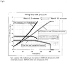
- Fig. 5 and Fig. 6 show the filling flow rate and pressure and temperature changes by the expansion (valve expansion) using the expansion valve of hydrogen gas (conventional system) and the expansion turbine/compressor type high-pressure hydrogen filling system of this invention (embodiment).
- the expansion turbine/compressor type high-pressure hydrogen filling system of this invention for the hydrogen pre-cool system used for lowering the temperature of hydrogen gas in the final filling portion of a hydrogen station, it is possible to fill the hydrogen gas expanded by driving the expansion turbine/compressor 11 by utilizing the pressure difference from the high pressure (82MPa) (main pressure) of the hydrogen gas source line 9 directly into the fuel tank of a hydrogen automobile.
- the high pressure 82MPa
- main pressure main pressure
- one unit of expansion turbine/compressor 11 is used in the embodiment shown in Fig. 3 but multiple units can be arranged in series as shown in the modified embodiment shown in Fig. 4 , and the multiple units arranged in series can be arranged in parallel.
- This makes it possible to operate the expansion turbine/compressor 11 with the expansion rate in the maximum area at each expansion ratio, secure room for the cost generation, easily increase the equipment flow rate, and make the filling equipment for large fuel cell bus and truck without a large pre-cool cooler.
- the cooler 12 and controller 14 are provided in the entrance portion on the expansion turbine 11a side of the expansion turbine/compressor 11 so as to control the exit temperature of the hydrogen gas of the cooler 12.
- Such configuration can properly lower the exit temperature of hydrogen gas of the cooler 12, thus making it possible to secure some room for the temperature in the fuel tank at completion of filling.
- Fig. 7 by lowering the exit temperature of hydrogen gas of the cooler 12 from ordinary temperature of about 33C to 25C or 20C by means of the controller 14, it is possible to secure room for the temperature rise in the fuel tank 6 after filling, making it possible to design the process with an expansion turbine of lower efficiency, as shown in Fig. 8 . That is, the target temperature can be achieved by adjusting the cold of the cooler 12 instead of lowering the temperature with a new cooler.
- the control of the protocol to fill hydrogen gas into the fuel tank 6 is to be made by the controller provided in the hydrogen gas supply unit 13.
- the filling can be done with minimum external energy without doing wasteful cooling by internally calculating the optimum cold to meet the filling time allocation specified in advance and through optimum control of the entrance temperature of the expansion turbine 11a (exit temperature of cooler 12).
- the expansion turbine/compressor type high-pressure hydrogen filling system and the control method of this invention is characterized in that the configuration is simple, site work cost is low, the load of maintenance work is small, the operating cost including the cost of power consumption is small, and it is not necessary to separately provide a means to take out the energy produced in the expansion equipment and effectively utilize outside such as generator, and so it can be preferably used for the application of the hydrogen pre-cool system in the final filling portion of the hydrogen station.
Landscapes
- Engineering & Computer Science (AREA)
- Mechanical Engineering (AREA)
- General Engineering & Computer Science (AREA)
- Filling Or Discharging Of Gas Storage Vessels (AREA)
- Fuel Cell (AREA)
Applications Claiming Priority (3)
| Application Number | Priority Date | Filing Date | Title |
|---|---|---|---|
| JP2016032073 | 2016-02-23 | ||
| JP2016032072 | 2016-02-23 | ||
| PCT/JP2017/004669 WO2017145769A1 (ja) | 2016-02-23 | 2017-02-09 | 高圧水素の膨張タービン・コンプレッサ式充填システム及びその制御方法 |
Publications (2)
| Publication Number | Publication Date |
|---|---|
| EP3421865A1 true EP3421865A1 (de) | 2019-01-02 |
| EP3421865A4 EP3421865A4 (de) | 2019-10-30 |
Family
ID=59685579
Family Applications (1)
| Application Number | Title | Priority Date | Filing Date |
|---|---|---|---|
| EP17756210.5A Withdrawn EP3421865A4 (de) | 2016-02-23 | 2017-02-09 | Expansionsturbine und hochdruckwasserstofffüllsystem vom verdichtertyp sowie steuerungsverfahren dafür |
Country Status (5)
| Country | Link |
|---|---|
| US (1) | US11015763B2 (de) |
| EP (1) | EP3421865A4 (de) |
| KR (1) | KR102173489B1 (de) |
| CN (1) | CN108700259B (de) |
| WO (1) | WO2017145769A1 (de) |
Cited By (1)
| Publication number | Priority date | Publication date | Assignee | Title |
|---|---|---|---|---|
| WO2022245427A3 (en) * | 2021-03-31 | 2023-03-02 | Zeroavia Ltd. | Refueling system for hydrogen fuel cell-powered aircraft |
Families Citing this family (5)
| Publication number | Priority date | Publication date | Assignee | Title |
|---|---|---|---|---|
| FR3098274B1 (fr) * | 2019-07-03 | 2022-01-28 | Air Liquide | Dispositif et procédé de remplissage de réservoirs. |
| DE102019132546A1 (de) * | 2019-11-29 | 2021-06-02 | Deutsches Zentrum für Luft- und Raumfahrt e.V. | Energiebereitstellungssystem, Fahrzeug und Verfahren zur Bereitstellung von Energie |
| CN114738665B (zh) * | 2022-04-24 | 2023-06-09 | 自贡东方通用压缩机有限公司 | 车辆氢气加注系统及加注方法 |
| DE102022122057A1 (de) * | 2022-08-31 | 2024-02-29 | Rwe Gas Storage West Gmbh | Brenngasspeichersystem |
| US20240384676A1 (en) * | 2023-05-17 | 2024-11-21 | Barry Doran | High Efficiency Thermo-Electric Power Generation for Hybrid Vehicles |
Family Cites Families (57)
| Publication number | Priority date | Publication date | Assignee | Title |
|---|---|---|---|---|
| JP4324716B2 (ja) * | 1999-11-26 | 2009-09-02 | 株式会社島津製作所 | ガスタービン装置 |
| US6628006B2 (en) * | 2001-05-03 | 2003-09-30 | Ford Motor Company | System and method for recovering potential energy of a hydrogen gas fuel supply for use in a vehicle |
| JP2004116619A (ja) | 2002-09-25 | 2004-04-15 | Nippon Sanso Corp | 燃料充てん装置および方法 |
| US7406987B2 (en) * | 2002-09-25 | 2008-08-05 | Taiyo Nippon Sanso Corporation | Apparatus and method for filling fuel |
| US6792981B1 (en) * | 2003-04-09 | 2004-09-21 | Praxair Technology, Inc. | Method and apparatus for filling a pressure vessel having application to vehicle fueling |
| GB0406615D0 (en) * | 2004-03-24 | 2004-04-28 | Air Prod & Chem | Process and apparatus for liquefying hydrogen |
| EP1603180A1 (de) * | 2004-05-31 | 2005-12-07 | C.R.F. Societa' Consortile per Azioni | Vorrichtung zur Rückführung für ein Brennstoffzellensystem |
| US7188478B2 (en) * | 2004-09-13 | 2007-03-13 | General Electric Company | Power generation system and method of operating same |
| US7273044B2 (en) * | 2004-09-27 | 2007-09-25 | Flessner Stephen M | Hydrogen fuel system for an internal combustion engine |
| CA2585211A1 (en) * | 2004-11-05 | 2006-05-18 | Exxonmobil Upstream Research Company | Lng transportation vessel and method for transporting hydrocarbons |
| DE102005032556B4 (de) * | 2005-07-11 | 2007-04-12 | Atlas Copco Energas Gmbh | Anlage und Verfahren zur Nutzung eines Gases |
| FR2919375B1 (fr) * | 2007-07-23 | 2009-10-09 | Air Liquide | Procede de remplissage d'un gaz sous pression dans un reservoir. |
| US7987877B2 (en) * | 2007-12-14 | 2011-08-02 | Texaco Inc. | Method for managing storage of gaseous hydrogen |
| JP5461791B2 (ja) * | 2008-06-18 | 2014-04-02 | トキコテクノ株式会社 | ガス充填方法及びガス充填装置 |
| DE102008034499A1 (de) * | 2008-07-24 | 2010-01-28 | Linde Ag | Speichervorrichtung für komprimierte Medien und Verfahren zum Betanken von Fahrzeugen |
| WO2010093400A1 (en) * | 2009-02-11 | 2010-08-19 | Exxonmobil Upstream Research Company | Methods and systems of regenerative heat exchange |
| JP4997259B2 (ja) * | 2009-02-27 | 2012-08-08 | 本田技研工業株式会社 | 水電解システム |
| JP5525188B2 (ja) * | 2009-06-09 | 2014-06-18 | 本田技研工業株式会社 | 水素充填装置及び水素充填方法 |
| US9182170B2 (en) * | 2009-10-13 | 2015-11-10 | Praxair Technology, Inc. | Oxygen vaporization method and system |
| NO332687B1 (no) * | 2009-10-21 | 2012-12-10 | Nel Hydrogen As | Fremgangsmate for operasjonen og styring ved gassfylling |
| WO2011061169A1 (en) * | 2009-11-18 | 2011-05-26 | Shell Internationale Research Maatschappij B.V. | Method of handling a boil off gas stream and an apparatus therefor |
| JP5328617B2 (ja) * | 2009-11-18 | 2013-10-30 | トヨタ自動車株式会社 | ガス充填システム、ガス充填方法、車両 |
| JP5707727B2 (ja) * | 2010-04-23 | 2015-04-30 | トヨタ自動車株式会社 | ガス充填方法、ガス充填システム、ガスステーション及び移動体 |
| FR2960041B1 (fr) * | 2010-05-11 | 2013-07-05 | Air Liquide | Dispositif et procede de remplissage d'un gaz sous pression dans un reservoir |
| DE102010035860A1 (de) * | 2010-08-30 | 2012-03-01 | Daimler Ag | Brennstoffzellensystem |
| US8656938B2 (en) * | 2010-11-29 | 2014-02-25 | GM Global Technology Operations LLC | Compressed gas tank system with fast fueling ability at any vessel pressure |
| FR2973858B1 (fr) * | 2011-04-06 | 2014-09-05 | Air Liquide | Procede et station de remplissage d'un reservoir |
| JP5824229B2 (ja) * | 2011-04-08 | 2015-11-25 | 川崎重工業株式会社 | 液化システム |
| DK2703709T3 (da) * | 2011-04-26 | 2019-05-06 | Kobe Steel Ltd | Hydrogen station. |
| CH706202A1 (de) * | 2012-03-07 | 2013-09-13 | Airlight Energy Ip Sa | Druckluftspeicherkraftwerk. |
| FR2988695B1 (fr) * | 2012-03-27 | 2015-02-20 | Air Liquide | Dispositif et procede de remplissage de reservoir |
| US20130305744A1 (en) * | 2012-05-21 | 2013-11-21 | General Electric Company | Cng delivery system with cryocooler and method of supplying purified cng |
| JP6021430B2 (ja) * | 2012-05-22 | 2016-11-09 | 川崎重工業株式会社 | 液体水素貯槽から発生するボイルオフガスの再液化方法 |
| CA2912650A1 (en) * | 2013-05-31 | 2014-12-04 | Nuvera Fuel Cells, Inc. | Distributed hydrogen refueling cascade method and system |
| FR3008166B1 (fr) * | 2013-07-05 | 2015-06-26 | Air Liquide | Station et procede de remplissage de reservoirs de gaz |
| US9982843B2 (en) * | 2013-07-08 | 2018-05-29 | The Boeing Company | Systems and methods for maintaining pressure in cryogenic storage tanks |
| FR3008473B1 (fr) * | 2013-07-11 | 2015-07-17 | Air Liquide | Procede et station de remplissage de gaz |
| GB201313307D0 (en) * | 2013-07-25 | 2013-09-11 | Corac Energy Technologies Ltd | System, method and apparatus |
| JP6123601B2 (ja) | 2013-09-18 | 2017-05-10 | コベルコ建機株式会社 | 排土板 |
| WO2015065996A1 (en) * | 2013-10-28 | 2015-05-07 | Alternative Fuel Containers, Llc | Fuel gas tank filling system and method |
| JP6279340B2 (ja) * | 2014-02-14 | 2018-02-14 | 株式会社神戸製鋼所 | ガス供給装置、水素ステーション及びガス供給方法 |
| US10634283B2 (en) * | 2014-02-21 | 2020-04-28 | Kobe Steel, Ltd. | Gas supply system and hydrogen station |
| US10145510B2 (en) * | 2014-04-10 | 2018-12-04 | Luxfer-Gtm Technologies, Llc | Mobile compressed gas refueler |
| WO2015170670A1 (ja) * | 2014-05-07 | 2015-11-12 | 日産自動車株式会社 | 燃料ガス充填システム及び燃料ガス充填方法 |
| EP3174145B1 (de) * | 2014-07-24 | 2019-06-05 | Nissan Motor Co., Ltd | Brennstoffzellensystem |
| JP6473033B2 (ja) * | 2014-10-31 | 2019-02-20 | 株式会社神戸製鋼所 | ガス供給システムおよび水素ステーション |
| US10088109B2 (en) * | 2014-11-03 | 2018-10-02 | Gilbarco Inc. | Compressed gas filling method and system |
| DE102015200473B4 (de) * | 2015-01-14 | 2024-01-18 | Audi Ag | Verfahren zum Überführen eines Brennstoffzellensystems in einen Stand-by-Modus sowie entsprechendes Brennstoffzellensystem |
| FR3032257B1 (fr) * | 2015-02-04 | 2017-07-14 | Air Liquide | Procede et un dispositif de remplissage de reservoir d'hydrogene |
| JP6526984B2 (ja) * | 2015-02-20 | 2019-06-05 | 株式会社神戸製鋼所 | ガス充填システム |
| FR3033867B1 (fr) * | 2015-03-17 | 2018-06-29 | L'air Liquide, Societe Anonyme Pour L'etude Et L'exploitation Des Procedes Georges Claude | Procede de remplissage de reservoirs avec du gaz sous pression |
| JP2016176592A (ja) * | 2015-03-23 | 2016-10-06 | 株式会社日立プラントメカニクス | 水素プレクールシステム |
| JP6404169B2 (ja) * | 2015-04-02 | 2018-10-10 | 株式会社神戸製鋼所 | 圧縮機ユニットおよびガス供給装置 |
| US20160348551A1 (en) * | 2015-05-30 | 2016-12-01 | Marius Angelo Paul | Universal zero carbon thermal electric clean engines with maximum absolute efficiency and power density, and supreme universal mobility |
| ES2743317T3 (es) * | 2016-01-18 | 2020-02-18 | Cryostar Sas | Sistema para licuar un gas |
| JP6643105B2 (ja) * | 2016-01-22 | 2020-02-12 | 伸和コントロールズ株式会社 | 冷却水素供給ステーション及び水素冷却装置 |
| US9810129B2 (en) * | 2016-03-08 | 2017-11-07 | Toyota Motor Engineering & Manufacturing North America, Inc. | Integrated waste heat recovery and motor assisted turbocharger system |
-
2017
- 2017-02-09 EP EP17756210.5A patent/EP3421865A4/de not_active Withdrawn
- 2017-02-09 WO PCT/JP2017/004669 patent/WO2017145769A1/ja not_active Ceased
- 2017-02-09 KR KR1020187027607A patent/KR102173489B1/ko active Active
- 2017-02-09 US US16/076,210 patent/US11015763B2/en active Active
- 2017-02-09 CN CN201780012629.XA patent/CN108700259B/zh active Active
Cited By (1)
| Publication number | Priority date | Publication date | Assignee | Title |
|---|---|---|---|---|
| WO2022245427A3 (en) * | 2021-03-31 | 2023-03-02 | Zeroavia Ltd. | Refueling system for hydrogen fuel cell-powered aircraft |
Also Published As
| Publication number | Publication date |
|---|---|
| KR20180136442A (ko) | 2018-12-24 |
| CN108700259B (zh) | 2020-12-29 |
| CN108700259A (zh) | 2018-10-23 |
| WO2017145769A1 (ja) | 2017-08-31 |
| EP3421865A4 (de) | 2019-10-30 |
| KR102173489B1 (ko) | 2020-11-03 |
| US11015763B2 (en) | 2021-05-25 |
| US20190178446A1 (en) | 2019-06-13 |
Similar Documents
| Publication | Publication Date | Title |
|---|---|---|
| US11015763B2 (en) | Expansion turbine and compressor-type high-pressure hydrogen filling system and control method for same | |
| US20240019216A1 (en) | Energy storage device and method based on carbon dioxide gas-liquid phase change | |
| US20240003272A1 (en) | Multistage-compression energy storage apparatus and method based on carbon dioxide gas-liquid phase change | |
| US20160281928A1 (en) | Hydrogen precooling system | |
| KR20150131255A (ko) | 저등급 폐열 관리를 위한 장치, 시스템 및 방법 | |
| US20180283275A1 (en) | Compressed air energy storage power generation apparatus and compressed air energy storage power generation method | |
| KR102173491B1 (ko) | 고압 수소의 팽창 터빈식 충전 시스템 | |
| US11585231B2 (en) | Device and method for operating volumetric expansion machines | |
| US20200063658A1 (en) | Compressed air storage power generation device | |
| JP2017083082A (ja) | ヒートポンプ | |
| JP7660472B2 (ja) | 水素ステーション | |
| US9341401B2 (en) | Heat source system and control method therefor | |
| EP1509733B1 (de) | Durch entspannung angetriebener motor für hilfsgeräte | |
| Wang et al. | Thermodynamic investigation of a centrifugal reverse Brayton cycle for refrigeration in air conditioning filed | |
| JP6525262B2 (ja) | 水素プレクールシステム | |
| JP2017150661A (ja) | 高圧水素の膨張タービン・コンプレッサ式充填システムの制御方法 | |
| JP2020079628A (ja) | 高圧水素の膨張タービン式充填システム | |
| JP6231245B1 (ja) | 高圧水素の膨張タービン式充填システム | |
| JPWO2008136121A1 (ja) | 天然ガス液化設備 | |
| JP6796505B2 (ja) | 高圧水素の膨張タービン・コンプレッサ式充填システム | |
| JP2025152135A (ja) | 蓄圧システム及び蓄圧システムの運転方法 | |
| US20210247107A1 (en) | Method and system for cooling a motor during motor startup |
Legal Events
| Date | Code | Title | Description |
|---|---|---|---|
| STAA | Information on the status of an ep patent application or granted ep patent |
Free format text: STATUS: THE INTERNATIONAL PUBLICATION HAS BEEN MADE |
|
| PUAI | Public reference made under article 153(3) epc to a published international application that has entered the european phase |
Free format text: ORIGINAL CODE: 0009012 |
|
| STAA | Information on the status of an ep patent application or granted ep patent |
Free format text: STATUS: REQUEST FOR EXAMINATION WAS MADE |
|
| 17P | Request for examination filed |
Effective date: 20180719 |
|
| AK | Designated contracting states |
Kind code of ref document: A1 Designated state(s): AL AT BE BG CH CY CZ DE DK EE ES FI FR GB GR HR HU IE IS IT LI LT LU LV MC MK MT NL NO PL PT RO RS SE SI SK SM TR |
|
| AX | Request for extension of the european patent |
Extension state: BA ME |
|
| DAV | Request for validation of the european patent (deleted) | ||
| DAX | Request for extension of the european patent (deleted) | ||
| A4 | Supplementary search report drawn up and despatched |
Effective date: 20190926 |
|
| RIC1 | Information provided on ipc code assigned before grant |
Ipc: F17C 5/06 20060101AFI20190920BHEP |
|
| RAP1 | Party data changed (applicant data changed or rights of an application transferred) |
Owner name: HITACHI PLANT MECHANICS CO. LTD. |
|
| STAA | Information on the status of an ep patent application or granted ep patent |
Free format text: STATUS: THE APPLICATION HAS BEEN WITHDRAWN |
|
| 18W | Application withdrawn |
Effective date: 20200918 |