EP3421872B1 - Beleuchtungsvorrichtung für kraftfahrzeug, die mit einem geführten kabelstrang ausgestattet ist - Google Patents
Beleuchtungsvorrichtung für kraftfahrzeug, die mit einem geführten kabelstrang ausgestattet ist Download PDFInfo
- Publication number
- EP3421872B1 EP3421872B1 EP18179654.1A EP18179654A EP3421872B1 EP 3421872 B1 EP3421872 B1 EP 3421872B1 EP 18179654 A EP18179654 A EP 18179654A EP 3421872 B1 EP3421872 B1 EP 3421872B1
- Authority
- EP
- European Patent Office
- Prior art keywords
- printed circuit
- housing
- rib
- lighting device
- cable harness
- Prior art date
- Legal status (The legal status is an assumption and is not a legal conclusion. Google has not performed a legal analysis and makes no representation as to the accuracy of the status listed.)
- Active
Links
Images



Classifications
-
- F—MECHANICAL ENGINEERING; LIGHTING; HEATING; WEAPONS; BLASTING
- F21—LIGHTING
- F21S—NON-PORTABLE LIGHTING DEVICES; SYSTEMS THEREOF; VEHICLE LIGHTING DEVICES SPECIALLY ADAPTED FOR VEHICLE EXTERIORS
- F21S45/00—Arrangements within vehicle lighting devices specially adapted for vehicle exteriors, for purposes other than emission or distribution of light
-
- F—MECHANICAL ENGINEERING; LIGHTING; HEATING; WEAPONS; BLASTING
- F21—LIGHTING
- F21S—NON-PORTABLE LIGHTING DEVICES; SYSTEMS THEREOF; VEHICLE LIGHTING DEVICES SPECIALLY ADAPTED FOR VEHICLE EXTERIORS
- F21S41/00—Illuminating devices specially adapted for vehicle exteriors, e.g. headlamps
- F21S41/10—Illuminating devices specially adapted for vehicle exteriors, e.g. headlamps characterised by the light source
- F21S41/19—Attachment of light sources or lamp holders
- F21S41/192—Details of lamp holders, terminals or connectors
-
- F—MECHANICAL ENGINEERING; LIGHTING; HEATING; WEAPONS; BLASTING
- F21—LIGHTING
- F21S—NON-PORTABLE LIGHTING DEVICES; SYSTEMS THEREOF; VEHICLE LIGHTING DEVICES SPECIALLY ADAPTED FOR VEHICLE EXTERIORS
- F21S41/00—Illuminating devices specially adapted for vehicle exteriors, e.g. headlamps
- F21S41/10—Illuminating devices specially adapted for vehicle exteriors, e.g. headlamps characterised by the light source
- F21S41/14—Illuminating devices specially adapted for vehicle exteriors, e.g. headlamps characterised by the light source characterised by the type of light source
- F21S41/141—Light emitting diodes [LED]
-
- F—MECHANICAL ENGINEERING; LIGHTING; HEATING; WEAPONS; BLASTING
- F21—LIGHTING
- F21S—NON-PORTABLE LIGHTING DEVICES; SYSTEMS THEREOF; VEHICLE LIGHTING DEVICES SPECIALLY ADAPTED FOR VEHICLE EXTERIORS
- F21S41/00—Illuminating devices specially adapted for vehicle exteriors, e.g. headlamps
- F21S41/10—Illuminating devices specially adapted for vehicle exteriors, e.g. headlamps characterised by the light source
- F21S41/14—Illuminating devices specially adapted for vehicle exteriors, e.g. headlamps characterised by the light source characterised by the type of light source
- F21S41/141—Light emitting diodes [LED]
- F21S41/143—Light emitting diodes [LED] the main emission direction of the LED being parallel to the optical axis of the illuminating device
-
- F—MECHANICAL ENGINEERING; LIGHTING; HEATING; WEAPONS; BLASTING
- F21—LIGHTING
- F21S—NON-PORTABLE LIGHTING DEVICES; SYSTEMS THEREOF; VEHICLE LIGHTING DEVICES SPECIALLY ADAPTED FOR VEHICLE EXTERIORS
- F21S41/00—Illuminating devices specially adapted for vehicle exteriors, e.g. headlamps
- F21S41/20—Illuminating devices specially adapted for vehicle exteriors, e.g. headlamps characterised by refractors, transparent cover plates, light guides or filters
- F21S41/285—Refractors, transparent cover plates, light guides or filters not provided in groups F21S41/24 - F21S41/2805
-
- F—MECHANICAL ENGINEERING; LIGHTING; HEATING; WEAPONS; BLASTING
- F21—LIGHTING
- F21S—NON-PORTABLE LIGHTING DEVICES; SYSTEMS THEREOF; VEHICLE LIGHTING DEVICES SPECIALLY ADAPTED FOR VEHICLE EXTERIORS
- F21S43/00—Signalling devices specially adapted for vehicle exteriors, e.g. brake lamps, direction indicator lights or reversing lights
- F21S43/10—Signalling devices specially adapted for vehicle exteriors, e.g. brake lamps, direction indicator lights or reversing lights characterised by the light source
- F21S43/13—Signalling devices specially adapted for vehicle exteriors, e.g. brake lamps, direction indicator lights or reversing lights characterised by the light source characterised by the type of light source
- F21S43/14—Light emitting diodes [LED]
-
- F—MECHANICAL ENGINEERING; LIGHTING; HEATING; WEAPONS; BLASTING
- F21—LIGHTING
- F21S—NON-PORTABLE LIGHTING DEVICES; SYSTEMS THEREOF; VEHICLE LIGHTING DEVICES SPECIALLY ADAPTED FOR VEHICLE EXTERIORS
- F21S45/00—Arrangements within vehicle lighting devices specially adapted for vehicle exteriors, for purposes other than emission or distribution of light
- F21S45/10—Protection of lighting devices
-
- F—MECHANICAL ENGINEERING; LIGHTING; HEATING; WEAPONS; BLASTING
- F21—LIGHTING
- F21V—FUNCTIONAL FEATURES OR DETAILS OF LIGHTING DEVICES OR SYSTEMS THEREOF; STRUCTURAL COMBINATIONS OF LIGHTING DEVICES WITH OTHER ARTICLES, NOT OTHERWISE PROVIDED FOR
- F21V23/00—Arrangement of electric circuit elements in or on lighting devices
- F21V23/001—Arrangement of electric circuit elements in or on lighting devices the elements being electrical wires or cables
-
- F—MECHANICAL ENGINEERING; LIGHTING; HEATING; WEAPONS; BLASTING
- F21—LIGHTING
- F21V—FUNCTIONAL FEATURES OR DETAILS OF LIGHTING DEVICES OR SYSTEMS THEREOF; STRUCTURAL COMBINATIONS OF LIGHTING DEVICES WITH OTHER ARTICLES, NOT OTHERWISE PROVIDED FOR
- F21V23/00—Arrangement of electric circuit elements in or on lighting devices
- F21V23/001—Arrangement of electric circuit elements in or on lighting devices the elements being electrical wires or cables
- F21V23/002—Arrangements of cables or conductors inside a lighting device, e.g. means for guiding along parts of the housing or in a pivoting arm
-
- F—MECHANICAL ENGINEERING; LIGHTING; HEATING; WEAPONS; BLASTING
- F21—LIGHTING
- F21V—FUNCTIONAL FEATURES OR DETAILS OF LIGHTING DEVICES OR SYSTEMS THEREOF; STRUCTURAL COMBINATIONS OF LIGHTING DEVICES WITH OTHER ARTICLES, NOT OTHERWISE PROVIDED FOR
- F21V23/00—Arrangement of electric circuit elements in or on lighting devices
- F21V23/003—Arrangement of electric circuit elements in or on lighting devices the elements being electronics drivers or controllers for operating the light source, e.g. for a LED array
- F21V23/007—Arrangement of electric circuit elements in or on lighting devices the elements being electronics drivers or controllers for operating the light source, e.g. for a LED array enclosed in a casing
- F21V23/009—Arrangement of electric circuit elements in or on lighting devices the elements being electronics drivers or controllers for operating the light source, e.g. for a LED array enclosed in a casing the casing being inside the housing of the lighting device
-
- F—MECHANICAL ENGINEERING; LIGHTING; HEATING; WEAPONS; BLASTING
- F21—LIGHTING
- F21V—FUNCTIONAL FEATURES OR DETAILS OF LIGHTING DEVICES OR SYSTEMS THEREOF; STRUCTURAL COMBINATIONS OF LIGHTING DEVICES WITH OTHER ARTICLES, NOT OTHERWISE PROVIDED FOR
- F21V23/00—Arrangement of electric circuit elements in or on lighting devices
- F21V23/02—Arrangement of electric circuit elements in or on lighting devices the elements being transformers, impedances or power supply units, e.g. a transformer with a rectifier
- F21V23/023—Power supplies in a casing
-
- F—MECHANICAL ENGINEERING; LIGHTING; HEATING; WEAPONS; BLASTING
- F21—LIGHTING
- F21V—FUNCTIONAL FEATURES OR DETAILS OF LIGHTING DEVICES OR SYSTEMS THEREOF; STRUCTURAL COMBINATIONS OF LIGHTING DEVICES WITH OTHER ARTICLES, NOT OTHERWISE PROVIDED FOR
- F21V27/00—Cable-stowing arrangements structurally associated with lighting devices, e.g. reels
-
- H—ELECTRICITY
- H01—ELECTRIC ELEMENTS
- H01B—CABLES; CONDUCTORS; INSULATORS; SELECTION OF MATERIALS FOR THEIR CONDUCTIVE, INSULATING OR DIELECTRIC PROPERTIES
- H01B7/00—Insulated conductors or cables characterised by their form
- H01B7/0045—Cable-harnesses
-
- H—ELECTRICITY
- H05—ELECTRIC TECHNIQUES NOT OTHERWISE PROVIDED FOR
- H05K—PRINTED CIRCUITS; CASINGS OR CONSTRUCTIONAL DETAILS OF ELECTRIC APPARATUS; MANUFACTURE OF ASSEMBLAGES OF ELECTRICAL COMPONENTS
- H05K5/00—Casings, cabinets or drawers for electric apparatus
- H05K5/0026—Casings, cabinets or drawers for electric apparatus provided with connectors and printed circuit boards [PCB], e.g. automotive electronic control units
- H05K5/0069—Casings, cabinets or drawers for electric apparatus provided with connectors and printed circuit boards [PCB], e.g. automotive electronic control units having connector relating features for connecting the connector pins with the PCB or for mounting the connector body with the housing
-
- H—ELECTRICITY
- H05—ELECTRIC TECHNIQUES NOT OTHERWISE PROVIDED FOR
- H05K—PRINTED CIRCUITS; CASINGS OR CONSTRUCTIONAL DETAILS OF ELECTRIC APPARATUS; MANUFACTURE OF ASSEMBLAGES OF ELECTRICAL COMPONENTS
- H05K5/00—Casings, cabinets or drawers for electric apparatus
- H05K5/02—Details
- H05K5/0217—Mechanical details of casings
-
- H—ELECTRICITY
- H05—ELECTRIC TECHNIQUES NOT OTHERWISE PROVIDED FOR
- H05K—PRINTED CIRCUITS; CASINGS OR CONSTRUCTIONAL DETAILS OF ELECTRIC APPARATUS; MANUFACTURE OF ASSEMBLAGES OF ELECTRICAL COMPONENTS
- H05K5/00—Casings, cabinets or drawers for electric apparatus
- H05K5/02—Details
- H05K5/0247—Electrical details of casings, e.g. terminals, passages for cables or wiring
-
- F—MECHANICAL ENGINEERING; LIGHTING; HEATING; WEAPONS; BLASTING
- F21—LIGHTING
- F21W—INDEXING SCHEME ASSOCIATED WITH SUBCLASSES F21K, F21L, F21S and F21V, RELATING TO USES OR APPLICATIONS OF LIGHTING DEVICES OR SYSTEMS
- F21W2107/00—Use or application of lighting devices on or in particular types of vehicles
- F21W2107/10—Use or application of lighting devices on or in particular types of vehicles for land vehicles
-
- H—ELECTRICITY
- H01—ELECTRIC ELEMENTS
- H01R—ELECTRICALLY-CONDUCTIVE CONNECTIONS; STRUCTURAL ASSOCIATIONS OF A PLURALITY OF MUTUALLY-INSULATED ELECTRICAL CONNECTING ELEMENTS; COUPLING DEVICES; CURRENT COLLECTORS
- H01R13/00—Details of coupling devices of the kinds covered by groups H01R12/70 or H01R24/00 - H01R33/00
- H01R13/73—Means for mounting coupling parts to apparatus or structures, e.g. to a wall
- H01R13/74—Means for mounting coupling parts in openings of a panel
- H01R13/741—Means for mounting coupling parts in openings of a panel using snap fastening means
- H01R13/743—Means for mounting coupling parts in openings of a panel using snap fastening means integral with the housing
Definitions
- the present invention relates to a lighting device for a motor vehicle.
- the invention also relates to a motor vehicle comprising such a lighting device.
- the invention also relates to a method for mounting such a lighting device in a motor vehicle.
- Motor vehicles include an increasing number of electrical or electronic equipment performing different functions.
- the operation of electrical or electronic equipment generates electromagnetic disturbances that can cause other equipment to malfunction. For this reason, maximum electromagnetic wave emission thresholds are imposed on each electrical or electronic equipment.
- the lighting devices of a motor vehicle must satisfy certain criteria for the emission of electromagnetic waves and for emissions conducted on the supply cables.
- Lighting devices must also meet aesthetic requirements. These requirements can result in a particular choice of light source such as diodes electroluminescent, a particular arrangement of light sources within the lighting device. In addition, in order to increase the comfort of use, the same lighting device must be able to operate according to several lighting modes differing for example by the intensity of lighting or the activation of different light sources at the same time. interior of the lighting device. Finally, lighting devices are subject to size requirements in order to use as little space as possible in the vehicle.
- the document JP2014135158 describes a lighting device for a motor vehicle, comprising a housing, a printed circuit provided with at least one light-emitting diode, and provided with an electromagnetic shielding cage, and an electrical harness fixed by a first end to the printed circuit and fixed by a second end to the housing.
- the object of the invention is to provide a lighting device and a method of mounting the lighting device making it possible to optimally achieve the above-mentioned requirements of the lighting devices and methods of mounting known to the prior art.
- the invention makes it possible to produce a device and a method for mounting the device which are simple to implement.
- the casing may include at least one rib intended to guide the path of the electrical harness inside the casing.
- the at least one rib can form with the housing a one-piece assembly, in particular a one-piece assembly made of injected plastic.
- the casing may comprise two ribs intended to guide the path of the beam inside the casing, the casing comprising a bottom extending along a plane substantially parallel to the printed circuit plane, a first rib extending from the bottom of the casing parallel to the axis perpendicular to the printed circuit plane, the housing comprising a side edge extending along a plane substantially perpendicular to the printed circuit plane, a second rib extending from the side edge of the housing parallel to the printed circuit plane .
- the electrical harness may include electromagnetic shielding, in particular a ferrite core.
- the lighting device may comprise a rear optical assembly comprising at least one collimator, in particular a Fresnel-type collimator, and a front optical assembly, separate from the rear optical assembly, provided with a front face comprising at least two surfaces of transverse lighting arranged at different levels in the longitudinal direction to form at least two steps of an overall staircase shape, the front optical assembly being stacked in direct contact with the rear optical assembly.
- a rear optical assembly comprising at least one collimator, in particular a Fresnel-type collimator
- a front optical assembly separate from the rear optical assembly, provided with a front face comprising at least two surfaces of transverse lighting arranged at different levels in the longitudinal direction to form at least two steps of an overall staircase shape, the front optical assembly being stacked in direct contact with the rear optical assembly.
- the rear optical assembly and the front optical assembly can each be presented in a single one-piece piece comprising at least each one holding means.
- the invention also relates to a motor vehicle comprising a lighting device as defined above.
- Step "f” can be performed after step “d” and after step “e”.
- Step "g” can be carried out after step “d” and after step “e”.
- Step “h” can be performed after step “f” and after step “g".
- a marker associated with a motor vehicle is defined. Left and right are defined from a driver's point of view.
- the X axis designates the longitudinal axis of the vehicle. In forward gear and in a straight line, the vehicle progresses from the rear to the front in a direction parallel to its longitudinal axis.
- the X axis is oriented from the front to the rear of the vehicle, that is to say in the direction of reverse gear.
- the Y axis designates the transverse axis of the vehicle.
- the Y axis is oriented from left to right.
- the Z axis refers to the axis perpendicular to the X axis and the Y axis.
- the Z axis is a vertical axis when the vehicle is resting on horizontal ground.
- the Z axis is oriented from bottom to top.
- the X, Y and Z axes form a direct orthonormal frame.
- the longitudinal axis X is therefore perpendicular to the vertical and transverse plane YZ.
- This same reference can be used to describe a lighting device even considered outside the vehicle since it is intended to be mounted in a particular orientation in the vehicle.
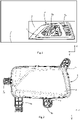
- the figure 1 schematically illustrates a motor vehicle 1 fitted with a lighting device 2 according to one embodiment of the invention.
- the lighting device is a projector and may be so called in the rest of the document.
- the projector shown is the left front projector.
- the vehicle can also comprise a right front headlight made symmetrically to the right of the vehicle and/or one or more headlights at the rear of the vehicle equipped with an embodiment of the invention.
- the vehicle could also be a truck, a bus, an industrial vehicle, a motorcycle or any other type of vehicle fitted with a headlight.
- the headlamp may comprise a position light, a dipped beam, a main beam, a fog light, a flashing light or any other light source contributing to the lighting of the vehicle and/or to the lighting of the road. Seen from the front, the headlamp has an overall trapezoidal shape with a large base that is substantially horizontal downwards and a small base that is also substantially horizontal and upwards, but the headlamp could have any other shape.
- the projector is fixed to a body of the vehicle and can be surrounded by a bodywork 3 of the vehicle.
- the projector comprises a translucent or transparent front face 4 protecting it from external attacks.
- the projector comprises two compartments 5a, 5b positioned side by side.
- a first compartment 5a can comprise for example lighting of the position light or dipped beam or daytime running light type.
- a second compartment 5b, positioned to the right of the first compartment 5a can for example comprise lighting of the main beam or fog light type.
- the figure 2 schematically illustrates the headlamp outside the vehicle.
- the headlamp comprises a casing 6 to which the front face 4 is fixed.
- the casing 6 comprises fixing means for fixing to the vehicle.
- the housing comprises four fixing lugs 7a, 7b, 7c, 7d.
- Two fixing lugs 7a, 7b extend vertically from a lower edge of the headlight.
- a third bracket 7c extends from a side edge to the right.
- a fourth bracket 7d extends from an upper left corner upwards and to the left.
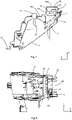
- the picture 3 shows a sectional and top view of the projector.
- the first compartment 5a comprises a first optical module 11 according to one embodiment of the invention.
- the second compartment comprises a second optical module 12.
- the second optical module comprises a light source, in this case a bulb 13, for example of the H8 type.
- the bulb may for example be a halogen bulb or a light-emitting diode bulb.
- the bulb is fixed through an opening 14 made in the bottom of the case. Such an opening is particularly visible on the figure 5 .
- the second optical module 12 comprises reflective surfaces 15 forming a funnel around the bulb and extending as far as the front face 4.
- the front face is common to the first and to the second optical module.
- the front face extends along a plane comprising roughly the vertical axis Z and an axis oblique to the transverse axis Y.
- the box 6 is generally a box made from injected plastic.
- the casing forms an envelope closed towards the front by the front face 4.
- the casing may include one or more sealing baffles at the interface with the front face.
- the casing is a one-piece plastic part enveloping the first and the second optical module.
- the housing comprises a common wall 17 between the first and the second optical module.
- the housing comprises a first bottom 18a at the rear of the first optical module and a second bottom 18b at the rear of the second optical module.
- the first and the second bottom extend along planes parallel to the vertical axis Z and to the transverse axis Y.
- the first bottom is offset with respect to the second bottom.
- the first bottom is positioned further to the rear than the second bottom.
- the projector could comprise only one optical module or more than two optical modules.
- the projector could also comprise a case specific to each optical module.
- the optical module 11 comprises a part of the housing 6 in which is housed a printed circuit 22 provided with at least one light source 23, a front optical assembly 20 and a rear optical assembly 19.
- the rear optical assembly 19 comprises at least one collimator, in particular a collimator of the Fresnel type.
- the front optical assembly 20 is separate from the rear optical assembly.
- the front optical assembly has a front face comprising at least two transverse lighting surfaces 21 arranged at different levels in the longitudinal direction to form at least two steps of an overall staircase shape.
- the front optical assembly is stacked in direct contact with the rear optical assembly.
- the rear optical assembly and the front optical assembly are each presented in a single one-piece piece comprising at least each one means for holding the housing.
- the printed circuit extends along a printed circuit plane YZ parallel to the bottom 18a of the case. That is to say, the printed circuit extends substantially parallel to the vertical axis Z and to the transverse axis Y.
- a volume 24 is delimited between the bottom 18a, the printed circuit and the side edges of the case.
- a right side edge 18c is positioned in the extension of the common wall 17.
- the at least one light source can be at least one light emitting diode.
- the optical module comprises a set of light-emitting diodes.
- the optical module may be capable of producing different lighting modes. For example, a first lighting mode can correspond to a position light and a second lighting mode can correspond to a daytime running light.
- the different lighting modes can be distinguished by the number of activated light-emitting diodes, the position of the activated light-emitting diodes, or even the light power delivered by each light-emitting diode.
- a first connector 25 passes through the bottom of the case along an axis substantially parallel to the axis X.
- the first connector comprises a first part positioned outside the housing intended to be connected to a secondary electrical harness.
- the first connector is a separate element of the housing.
- the first connector is fixed to the housing by a snap-fastening means 25b which is particularly visible on the figure 10 .
- the headlamp can be electrically connected to other components of the vehicle, in particular to an electronic control unit, and/or to an electrical power supply device.
- the first connector also comprises a second part positioned inside the housing and connected to an electrical harness 26.
- the electrical harness 26 comprises a first end connected to the first connector 25 and a second end connected to the printed circuit via a second connector 28.
- the light device could comprise no connector or comprise a single connector.
- the cables of the electrical harness could be soldered to the printed circuit or the electrical harness could simply pass through the housing, for example through a grommet, and be connected outside the housing to other parts of the vehicle.
- the first connector is oriented along the longitudinal axis X and passes through the bottom of the case.
- the first connector is located near the bottom right corner of the case.
- the second connector is also oriented along the longitudinal axis X on the printed circuit.
- the second connector is located near the lower right corner of the circuit board.
- the first connector and the second connector are therefore positioned very close to each other when the printed circuit is assembled to the housing.
- the distance separating the first connector from the second connector is significantly less than the length of the electrical harness. It can be pointed out that if the length of the electrical harness had been limited to the distance separating the first connector from the second connector, the assembly of the first connector to the housing and/or the second connector to the printed circuit would be impossible. Indeed, there would not be enough space between the printed circuit and the case to make these connections.
- the electrical harness includes three electrical cables of the same length.
- the minimum length of the electrical harness can be defined so as to be able to fix the first connector to the housing and/or the second connector to the printed circuit without difficulty when assembling the optical module.
- the maximum harness length can be set to optimize the amount of cable used.
- the electrical cables are not fixed together but are all three connected by a first end to the first connector and by a second end to the printed circuit.
- the electric cables can be metal wires surrounded by an insulating sheath.
- the electrical harness could include any other number of electrical cables greater than or equal to one.
- the electrical harness could also comprise a ferrite core 35 as represented on the figure 6 .
- the ferrite core comprises a metallic solid of revolution provided with a central opening through which the electric beam passes.
- the ferrite core may for example take the form of a ring or else of a cylinder provided with a cylindrical central opening.
- the ferrite core may comprise two semi-cylinders articulated by a hinge so as to be able to open for mounting around the electrical harness.
- the ferrite core does not need to be threaded through one end of the electrical harness to be assembled to the wiring harness.
- the ferrite core could surround only part of the cables of the electrical harness
- the electrical harness could comprise a sheath enveloping, at least locally, all the cables so that the routing of each cable is parallel to the routing of the other cables.
- the sheath could also include electromagnetic shielding, for example in the form of a metal braid surrounding all the cables.
- the printed circuit comprises a first face on which is fixed the at least one light source 23.
- the rear optical assembly is positioned against the first face of the printed circuit.
- the first face faces the front of the vehicle.
- the printed circuit comprises a second face, facing rearward, on which the electrical harness is fixed.
- the electrical harness can be connected to the second face of the printed circuit by means of metal plugs 27 arranged at the end of each cable of the harness inserted into the second connector 28. These plugs are particularly visible on the figures 7 and 8 .
- the plugs are oriented along the longitudinal axis X.
- the plugs are connected to the printed circuit via the second connector fixed to the second rear face of the printed circuit.
- the second face of the printed circuit also comprises a set of electronic components constituting a driver for the power supply, in particular a power converter of the chopper type comprising a coil.
- the electronic components can also constitute a driver for driving the at least one light source.
- These electronic components as well as the tracks which connect them between they are mainly responsible for emissions.
- These electronic components are surrounded by an electromagnetic shielding cage 29, also called a Faraday cage.
- the printed circuit may also include other electronic components outside the cage on the first face or on the second face of the printed circuit. It is specified that the connector 28 is not inside the cage 29. The electrical harness therefore does not cross the cage.
- the cage may have a generally parallelepipedic shape.
- the cage is positioned at the bottom of the printed circuit, to the left of the second connector.
- the cage can have a length of greater dimension than a width and the width of a greater dimension than a height.
- the length is substantially oriented along the vertical axis Z.
- the width is substantially oriented along the transverse axis Y.
- the height of the cage is substantially oriented along the longitudinal axis X.
- the cage could have any other shape, for example a cylindrical shape or a polygonal shape.
- the cage is generally made from sheets of steel, or any other conductive material.
- the steel sheets can be pierced with regularly distributed circular holes as is the case here on the rear face 30a.
- the shape of the printed circuit can match, at least roughly, the shape of the case.
- the printed circuit has a generally rectangular shape with a first extension 31a to the right from an upper right corner of the printed circuit and with a second extension 31b to the right from a lower right corner of the printed circuit.
- the right side edge 18c of the case includes a profile matching the profile of the right edge of the printed circuit.
- the housing having a shape complementary to the printed circuit, it is thus possible to ensure that the printed circuit is correctly oriented in the housing. In particular, an assembly of the printed circuit in the housing with a rotation of a quarter turn would be impossible.
- the box also includes pillars 32a, 32b, 32c, 32d extending parallel to the longitudinal axis X and making it possible to precisely define the position of the printed circuit inside the box.
- the printed circuit can rest on a first pillar 32a via a first extension 31a.
- the printed circuit can rest on a second pillar 32b via a second extension 31b.
- the printed circuit may also include openings 33a, 33b, in particular oblong or circular openings.
- a first opening 33a can cooperate with a third pillar 32c and a second opening 33b can cooperate with a fourth pillar 32d to block the position of the printed circuit with respect to the vertical axis Z and with respect to the transverse axis Y.
- the third pillar 32c and the fourth pillar 32d can also be used to fix the rear optical assembly 19 and the front optical assembly 20 on the housing.
- Other openings 33c, 33d made in the printed circuit can be used to fix the rear optical assembly 19 against the printed circuit.
- the printed circuit can also rest on the base 34 common to the third and fourth pillar.
- the first pillar, the second pillar and the base form three support points for the printed circuit and thus define the printed circuit plane.
- the position of the printed circuit in relation to the case is completely defined.
- the position and orientation of the at least one light source is precise.
- the electric beam is contained in the volume 24. In the absence of a guide means, the electric beam could follow any path inside the volume 24.
- the path of the electric beam can be governed by the position of the first and of the second connector as well as by the rigidity of the cables making up the electrical harness.
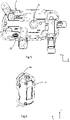
- a routing of the electrical harness can be illustrated on the figure 7 .
- the beam passes behind the cage.
- the projection of the beam along the longitudinal axis X intersects the projection of the cage along the longitudinal axis X.
- the beam makes a “U” shaped loop when it passes behind the cage.
- part of the power radiated by the electronic components inside the cage reaches the beam creating disturbances conducted in the beam which then becomes an antenna and produces electromagnetic disturbances
- the electromagnetic radiation emitted by the optical module can be measured.
- a measurement can be carried out for example according to an international standard or according to a standard of a car manufacturer defining the acceptable electromagnetic emission thresholds.
- We can represent the strength of the electromagnetic field as a function of its frequency on a logarithmic graph. More precisely, one can represent on the one hand a measurement corresponding to a temporal average of the power of the electromagnetic field as a function of the frequency.
- the international standard or the car manufacturer's standard defines maximum electromagnetic field power thresholds as a function of frequency.
- the international standard or the car manufacturer's standard also defines maximum frequency-dependent voltage thresholds for conducted emissions.
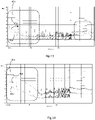
- the figure 11 represents a graph of the average voltage 41a and of the peak voltage 41b of the conducted emissions of the optical module on a frequency band comprised between 150 kHz and 200 MHz for the first lighting mode and with the first configuration of the electrical beam.
- the graph also includes the maximum thresholds for the average voltage levels 40a and for the peak voltage levels 40b defined by the international standard or by the car manufacturer's standard. It can be seen that the conducted emissions exceed the thresholds defined by the standard, in particular for a frequency band around 1.1 MHz.
- the figure 12 represents a graph of the average voltage 42a and of the peak voltage 42b of the conducted emissions of the optical module on a frequency band comprised between 150 kHz and 200 MHz for the second lighting mode and with the first configuration of the electrical beam.
- the graph also includes the thresholds maximum for average voltage levels 40a and for peak voltage levels 40b defined by the international standard or by the car manufacturer's standard. It can be seen that the conducted emissions exceed the thresholds defined by the standard, in particular for a frequency band around 530 KHz.
- the electromagnetic emission spectrum of the optical module is also modified. It is possible to define a second configuration C2 of the path of the electrical beam, in which the projection of the beam along the longitudinal axis X does not intersect the projection of the cage along the longitudinal axis X but runs along the right side edge 30d of the cage .
- the second configuration is particularly visible on the figure 8 and on the figure 9 .
- the printed circuit has been made invisible in order to allow the visualization of the path of the electrical harness in relation to the cage.
- the electrical harness By considering the path of the electrical harness from the second connector, that is to say the connector fixed to the printed circuit, to the first connector, that is to say the connector fixed to the housing, we can distinguish different sections of the wiring harness, differentiated by changes in the direction of the wiring harness.
- the changes of direction can for example be curvatures at an angle approximately equal to 90°.
- a first section 26a the electrical harness emerges perpendicular to the printed circuit plane YZ.
- the electrical harness rises upwards along the right side edge 30d of the cage parallel to the printed circuit plane.
- the electrical harness In a third section 26c, the electrical harness is oriented from left to right parallel to the printed circuit plane.
- the electrical harness moves away from the cage, but alternatively, it could also approach it without however passing behind the cage.
- the electrical harness descends downwards along the right side edge 18c of the box, parallel to the printed circuit plane.
- the electrical harness is oriented perpendicular to the printed circuit plane to emerge in the first connector.
- the beam is folded back on itself and does not draw a loop behind the cage that can be coupled with the magnetic field of the main coil of the power converter.
- the electric beam is far from the cage and does not draw a loop perpendicular to the electromagnetic field lines coming from the cage.
- the area of the projection of the electric beam along the longitudinal axis X is much smaller than for the first configuration C1 of the path of the electric beam.
- the beam could run along any other side edge of the cage.
- a guide means 50 of the harness is integrated into the casing.
- the guide means can be integrated into the bottom of the box and into the right side edge of the box, at the level of a portion of the beam extending along the vertical axis Z, along the right edge of the cage.
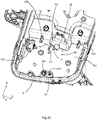
- the guide means 50 is particularly illustrated on the figure 9 and10.
- the housing comprises a first rib 51 extending from the bottom 18a of the housing parallel to the axis perpendicular to the printed circuit plane.
- the first rib therefore extends along the longitudinal axis X from the bottom of the case.
- the first rib has a generally rectangular shape and also extends parallel to the transverse axis Y.
- the first rib is positioned approximately halfway the bottom of the case along the vertical axis Z and close to the right side edge 18c of the case.
- a first space in which the electrical harness is housed separates the first rib from the right side edge.
- the electrical harness passes between the first rib 51 and the right side edge 18c.
- the first rib maintains the electrical bundle along the transverse axis Y.
- the housing also includes a second rib 52 extending from the right side edge 18c of the housing parallel to the printed circuit plane.
- the second rib therefore extends along the transverse axis Y and along the vertical axis Z.
- the second rib has a generally rectangular shape and is positioned approximately halfway up the side edge of the case between the bottom of the case and the printed circuit along the longitudinal axis X.
- a second space in which the electrical harness is housed separates the second rib from the bottom.
- the electrical harness passes between the second rib 52 and the bottom 18a of the case.
- the second rib maintains the electrical bundle along the longitudinal axis X.
- the second rib is positioned opposite the first rib.
- a space D1 separates the first rib from the second rib allowing passage of the electrical harness during assembly.
- the space can be adjusted according to the thickness of the beam to allow it to pass between the two ribs.
- Mounting the electrical harness between the two ribs may require local deformation of the ribs or of the harness in order to guarantee effective retention of the electrical harness once in place.
- the casing could comprise only one rib from among the first or the second rib.
- a rib could include a notch for receiving the beam.
- the box could also include more ribs and other means for guiding the beam distributed throughout its path.
- the first and the second rib are made in one piece with the casing during the same plastic injection operation.
- the injection mold may include drawers making it possible to produce the ribs.
- the injection mold can comprise a movable drawer along the transverse axis Y.
- the first rib and/or the second rib could be elements manufactured separately and fixed (for example clipped or glued) to the casing.
- the figure 13 represents a graph of the average voltage 43a and of the peak voltage 43b of the conducted emissions of the optical module on a frequency band comprised between 150 kHz and 200 MHz for the first lighting mode and with the second configuration of the beam.
- the graph also includes the maximum thresholds for the average voltage levels 40a and for the peak voltage levels 40b defined by the international standard or by the car manufacturer's standard. It can be seen that the conducted emissions comply with the thresholds defined by the standard.
- the figure 14 represents a graph of the average voltage 44a and of the peak voltage 44b of the conducted emissions of the optical module on a frequency band comprised between 150 kHz and 200 MHz for the second lighting mode and with the second beam configuration.
- the graph also includes the maximum thresholds for the average voltage levels 40a and for the peak voltage levels 40b defined by the international standard or by the car manufacturer's standard. It can be seen that the conducted emissions comply with the thresholds defined by the standard.
- step “f” and of step “g" the electrical harness is positioned along the cage according to the second configuration.
- step “f” and of step “g” the electrical harness is positioned along the cage according to the second configuration.
- the printed circuit is fixed inside the case.
- this step includes the insertion of the pillars 32c, 32d of the casing into the corresponding openings 33a, 33b of the printed circuit.
- the beam is confined in the volume 24 made inaccessible by the fixing of the printed circuit. The risk of the electrical harness coming out of its guide between the first rib and the edge of the case and between the second rib and the bottom of the case is therefore very low.
- the invention there is a lighting device able to produce several lighting modes.
- the size of this device is limited and the emissions of electromagnetic waves from the device allow it to be integrated into a vehicle without disturbing the operation of the others. electrical or electronic parts of the vehicle.
- the cost of such a lighting device remains moderate because it is not useful to add expensive components to limit the emission of conducted waves.
Landscapes
- Engineering & Computer Science (AREA)
- General Engineering & Computer Science (AREA)
- Microelectronics & Electronic Packaging (AREA)
- Physics & Mathematics (AREA)
- Optics & Photonics (AREA)
- Power Engineering (AREA)
- Lighting Device Outwards From Vehicle And Optical Signal (AREA)
- Non-Portable Lighting Devices Or Systems Thereof (AREA)
- Shielding Devices Or Components To Electric Or Magnetic Fields (AREA)
Claims (10)
- Beleuchtungsvorrichtung (11) für ein Kraftfahrzeug (1), umfassend:- ein Gehäuse (6),- eine Leiterplatte (22), die mit wenigstens einer Lichtquelle (23), insbesondere einer Lichtquelle (23) vom Typ Leuchtdiode, und mit einem Käfig (29) zur elektromagnetischen Abschirmung versehen ist, wobei sich die Leiterplatte (22) in einer Leiterplattenebene (YZ) erstreckt und im Inneren des Gehäuses (6) befestigt ist,- einen Kabelbaum (26), der durch ein erstes Ende an der Leiterplatte (22) und durch ein zweites Ende am Gehäuse (6) befestigt ist,dadurch gekennzeichnet, dass der Kabelbaum (26) einen Weg umfasst, dessen Projektion entlang einer Achse (X), die senkrecht zur Leiterplattenebene (YZ) verläuft, nicht die Projektion des Käfigs (29) entlang der Achse (X) schneidet, die senkrecht zur Leiterplattenebene (YZ) verläuft, und dadurch, dass der Kabelbaum (26) ein Teilstück umfasst, das sich entlang des Käfigs (29), insbesondere parallel zu einem Seitenrand (30d) des Käfigs (29) erstreckt.
- Beleuchtungsvorrichtung (11) nach dem vorhergehenden Anspruch, dadurch gekennzeichnet, dass das Gehäuse (6) wenigstens eine Rippe (51, 52) umfasst, die dazu bestimmt ist, den Weg des Kabelbaums (26) im Inneren des Gehäuses (6) zu führen.
- Beleuchtungsvorrichtung (11) nach dem vorhergehenden Anspruch, dadurch gekennzeichnet, dass die wenigstens eine Rippe (51, 52) mit dem Gehäuse (6) eine einstückige Anordnung bildet, insbesondere eine einstückige Anordnung, die aus spritzgegossenem Kunststoff gebildet ist.
- Beleuchtungsvorrichtung (11) nach einem der vorhergehenden Ansprüche, dadurch gekennzeichnet, dass das Gehäuse (6) zwei Rippen (51, 52) umfasst, die dazu bestimmt sind, den Weg des Kabelbaums im Inneren des Gehäuses (6) zu führen, wobei das Gehäuse (6) einen Boden (18a) umfasst, der sich in einer Ebene erstreckt, die im Wesentlichen parallel zur Leiterplattenebene (YZ) verläuft, wobei sich eine erste Rippe (51) von dem Boden (18a) des Gehäuses (6) parallel zu der Achse erstreckt, die senkrecht zur Leiterplattenebene (YZ) verläuft, wobei das Gehäuse (6) einen Seitenrand (18c) umfasst, der sich in einer Ebene erstreckt, die im Wesentlichen senkrecht zur Leiterplattenebene (YZ) verläuft, wobei sich eine zweite Rippe von dem Seitenrand (18c) des Gehäuses (6) parallel zur Leiterplattenebene (YZ) erstreckt.
- Beleuchtungsvorrichtung (11) nach einem der vorhergehenden Ansprüche, dadurch gekennzeichnet, dass der Kabelbaum (26) eine elektromagnetische Abschirmung umfasst, insbesondere einen Ferritkern.
- Beleuchtungsvorrichtung (11) nach einem der vorhergehenden Ansprüche, dadurch gekennzeichnet, dass sie eine hintere optische Anordnung (19), die wenigstens einen Kollimator umfasst, insbesondere einen Fresnel-Kollimator, und eine vordere optische Anordnung (20), die von der hinteren optischen Anordnung (19) gesondert ist, umfasst, die mit einer Vorderseite versehen ist, die wenigstens zwei Beleuchtungsflächen (21) in Querrichtung umfasst, die auf verschiedenen Ebenen in der Längsrichtung (X) angeordnet sind, um wenigstens zwei Stufen einer allgemeinen Treppenform zu bilden, wobei die vordere optische Anordnung (20) in direktem Kontakt mit der hinteren optischen Anordnung (19) gestapelt ist.
- Beleuchtungsvorrichtung (11) nach dem vorhergehenden Anspruch, dadurch gekennzeichnet, dass die hintere optische Anordnung (19) und die vordere optische Anordnung (20) jeweils einstückig ausgebildet sind, wobei sie wenigstens jeweils ein Haltemittel umfassen.
- Kraftfahrzeug (1) umfassend eine Beleuchtungsvorrichtung (11) nach einem der vorhergehenden Ansprüche.
- Verfahren zur Montage einer Beleuchtungsvorrichtung (11) nach einem der Ansprüche 1 bis 7 umfassend die folgenden Schritte:a. Herstellen einer Leiterplatte (22), die mit einem Käfig (29) zur elektromagnetischen Abschirmung und mit wenigstens einer Lichtquelle (23), insbesondere einer Lichtquelle (23) vom Typ Leuchtdiode, versehen ist;b. Herstellen eines Kabelbaums (26);c. Herstellen eines Gehäuses (6), das mit einer ersten Rippe (51) und einer zweiten Rippe (52) versehen ist, insbesondere Herstellen des Gehäuses (6) durch Kunststoffspritzguss;d. Befestigen eines ersten Endes des Kabelbaums (26) am Gehäuse (6);e. Befestigen eines zweiten Endes des Kabelbaums (26) an der Leiterplatte (22);f. Positionieren des Kabelbaums (26) zwischen einer ersten Rippe (51) und einem Seitenrand (18c) des Gehäuses (6),
und/oderg. Positionieren des Kabelbaums (26) zwischen einer zweiten Rippe (52) und einem Boden (18a) des Gehäuses (6) .h. Befestigen der Leiterplatte (22) im Inneren des Gehäuses (6). - Montageverfahren nach dem vorhergehenden Anspruch, dadurch gekennzeichnet, dass:- der Schritt "f" nach dem Schritt "d" und nach dem Schritt "e" durchgeführt wird; und/oder- der Schritt "g" nach dem Schritt "d" und nach dem Schritt "e" durchgeführt wird; und/oder- der Schritt "h" nach dem Schritt "f" und nach dem Schritt "g" durchgeführt wird.
Applications Claiming Priority (1)
| Application Number | Priority Date | Filing Date | Title |
|---|---|---|---|
| FR1756074A FR3068313B1 (fr) | 2017-06-29 | 2017-06-29 | Dispositif d'eclairage pour vehicule automobile muni d'un faisceau electrique guide |
Publications (2)
| Publication Number | Publication Date |
|---|---|
| EP3421872A1 EP3421872A1 (de) | 2019-01-02 |
| EP3421872B1 true EP3421872B1 (de) | 2023-01-11 |
Family
ID=59859294
Family Applications (1)
| Application Number | Title | Priority Date | Filing Date |
|---|---|---|---|
| EP18179654.1A Active EP3421872B1 (de) | 2017-06-29 | 2018-06-25 | Beleuchtungsvorrichtung für kraftfahrzeug, die mit einem geführten kabelstrang ausgestattet ist |
Country Status (4)
| Country | Link |
|---|---|
| US (1) | US10520154B2 (de) |
| EP (1) | EP3421872B1 (de) |
| CN (1) | CN109210495A (de) |
| FR (1) | FR3068313B1 (de) |
Families Citing this family (4)
| Publication number | Priority date | Publication date | Assignee | Title |
|---|---|---|---|---|
| JP2020096121A (ja) * | 2018-12-14 | 2020-06-18 | 住友電装株式会社 | シールドカバー及び組み付け体 |
| WO2021065820A1 (ja) * | 2019-09-30 | 2021-04-08 | 株式会社小糸製作所 | 光出射装置、ヘッドアップディスプレイ、車両用灯具、及びプロジェクタ |
| FR3102830A1 (fr) * | 2019-10-30 | 2021-05-07 | Psa Automobiles Sa | Dispositif de montage d’un boîtier de projecteur sur un véhicule automobile |
| FR3116160B1 (fr) * | 2020-11-09 | 2023-10-06 | Psa Automobiles Sa | Support de faisceaux a fonction integree pour dispositifs d’eclairage |
Family Cites Families (16)
| Publication number | Priority date | Publication date | Assignee | Title |
|---|---|---|---|---|
| DE19704067A1 (de) * | 1997-02-04 | 1998-08-06 | Bosch Gmbh Robert | Beleuchtungseinrichtung für Fahrzeuge |
| CN105093391B (zh) * | 2004-05-14 | 2022-12-02 | 莫莱克斯公司 | 光导管组件及连接器组件 |
| JP4656997B2 (ja) * | 2005-04-21 | 2011-03-23 | 株式会社小糸製作所 | 車両用灯具 |
| JP2007265909A (ja) * | 2006-03-29 | 2007-10-11 | Koito Mfg Co Ltd | 車両用灯具 |
| DE102009018445A1 (de) * | 2009-04-22 | 2010-10-28 | Automotive Lighting Reutlingen Gmbh | Beleuchtungseinrichtung eines Kraftfahrzeugs |
| DE102009030352A1 (de) * | 2009-06-22 | 2011-01-05 | Automotive Lighting Reutlingen Gmbh | Verfahren zum Verlegen und Vorrichtung zum Führen und Befestigen von Kabeln eines Kabelbaums im Inneren eines Gehäuses einer Beleuchtungseinrichtung eines Kraftfahrzeugs |
| KR101621794B1 (ko) * | 2010-01-07 | 2016-05-31 | 삼성전자 주식회사 | 디스플레이장치 |
| DE202010002406U1 (de) * | 2010-02-16 | 2010-05-06 | Automotive Lighting Reutlingen Gmbh | Beleuchtungseinrichtung eines Kraftfahrzeugs |
| CN202074433U (zh) * | 2011-03-02 | 2011-12-14 | 广东雪莱特光电科技股份有限公司 | 新型车用一体化氙气金卤灯 |
| JP2014135158A (ja) * | 2013-01-09 | 2014-07-24 | Stanley Electric Co Ltd | 車両用灯具 |
| DE102013218356A1 (de) * | 2013-09-13 | 2015-03-19 | Automotive Lighting Reutlingen Gmbh | Lichtmodul für eine Beleuchtungseinrichtung und Beleuchtungseinrichtung mit einem solchen Lichtmodul |
| FR3032516B1 (fr) | 2015-02-06 | 2021-04-16 | Valeo Vision | Dispositif reflecteur d'un module lumineux avec blindage electromagnetique |
| FR3037636A1 (fr) | 2015-06-22 | 2016-12-23 | Valeo Vision | Enveloppe de protection polymerique pour faisceaux electriques dans un dispositif lumineux de vehicule automobile |
| US10041645B2 (en) * | 2015-07-06 | 2018-08-07 | Panasonic Intellectual Property Management Co., Ltd. | Light source unit, lighting device, and vehicle |
| CN206036868U (zh) * | 2016-08-25 | 2017-03-22 | 众用车材制造股份有限公司 | 车灯 |
| CN206247201U (zh) * | 2016-11-29 | 2017-06-13 | 重庆秦川工贸有限公司 | 一种线束绕线导向固定卡扣 |
-
2017
- 2017-06-29 FR FR1756074A patent/FR3068313B1/fr not_active Expired - Fee Related
-
2018
- 2018-06-25 EP EP18179654.1A patent/EP3421872B1/de active Active
- 2018-06-29 US US16/023,599 patent/US10520154B2/en active Active
- 2018-06-29 CN CN201810714001.0A patent/CN109210495A/zh active Pending
Also Published As
| Publication number | Publication date |
|---|---|
| EP3421872A1 (de) | 2019-01-02 |
| CN109210495A (zh) | 2019-01-15 |
| US10520154B2 (en) | 2019-12-31 |
| FR3068313B1 (fr) | 2020-10-02 |
| FR3068313A1 (fr) | 2019-01-04 |
| US20190003672A1 (en) | 2019-01-03 |
Similar Documents
| Publication | Publication Date | Title |
|---|---|---|
| EP3421872B1 (de) | Beleuchtungsvorrichtung für kraftfahrzeug, die mit einem geführten kabelstrang ausgestattet ist | |
| EP2775197B1 (de) | Vorrichtung zur Beleuchtung und/oder Signalisierung für ein Kraftfahrzeug, die einen Lichtwellenleiter umfasst | |
| EP2921772B1 (de) | Leuchtmodul eines kraftfahrzeugs | |
| EP2966342B1 (de) | Beleuchtungsmodul eines projektionsscheinwerfers für ein kraftfahrzeug | |
| EP3055611A1 (de) | Beleuchtungs- oder anzeigevorrichtung für ein kraftfahrzeug und entsprechendes montageverfahren | |
| EP3884206B1 (de) | Multifunktionales lichtmodul mit zwei flachen lichtleitern | |
| FR3106651A1 (fr) | Guide de lumière plat pour module lumineux de signalisation de véhicule automobile | |
| FR3065401A1 (fr) | Module d'etancheite pour un vehicule automobile et son montage | |
| FR3088869A1 (fr) | Dispositif de pré-positionnement et de maintien d’un élément sur un boitier | |
| FR3058502A1 (fr) | Dispositif de montage sans vis d'un boitier de commande de projecteur sur ledit projecteur | |
| EP3443405B1 (de) | Head-up-anzeige | |
| EP2177398A1 (de) | Rückwärtige Signalleuchte für Kraftfahrzeug | |
| WO2017055781A1 (fr) | Agencement pour le montage de modules d'éclairage de différents modèles sur un même bouclier de véhicule automobile | |
| FR3152862A1 (fr) | Dispositif lumineux pour véhicule automobile | |
| EP3190004B1 (de) | Kabelführungsvorrichtung für eine leuchtvorrichtung eines kraftfahrzeugs | |
| EP2966340B1 (de) | Beleuchtungsmodul eines scheinwerfers für ein kraftfahrzeug | |
| FR2997049A1 (fr) | Dispositif de signalisation pour vehicule, notamment pour vehicule routier de transport de marchandises | |
| FR3050040B1 (fr) | Dispositif de projection d'images pour afficheur tete haute, afficheur tete haute associe et procede de fabrication d'un tel dispositif de projection d'images | |
| FR3072055B1 (fr) | Systeme support pour module de projection d’un dispositif d’affichage tete-haute de vehicule automobile | |
| FR3141401A1 (fr) | Pare-chocs pour véhicule automobile intégrant un bloc optique d’éclairage et/ou de signalisation | |
| WO2025045798A1 (fr) | Module d'éclairage pour un véhicule automobile | |
| FR3148948A1 (fr) | Véhicule automobile à projecteurs encastrés dans le bouclier de pare-chocs avant | |
| EP3221185B1 (de) | Leuchteinheit für ein fahrzeug und dazugehöriges fahrzeug | |
| WO2024175840A1 (fr) | Bloc optique de signalisation destiné à être intégré dans un projecteur de véhicule automobile | |
| WO2023012090A1 (fr) | Module lumineux destiné à être fixé à un dispositif lumineux de véhicule automobile |
Legal Events
| Date | Code | Title | Description |
|---|---|---|---|
| PUAI | Public reference made under article 153(3) epc to a published international application that has entered the european phase |
Free format text: ORIGINAL CODE: 0009012 |
|
| STAA | Information on the status of an ep patent application or granted ep patent |
Free format text: STATUS: REQUEST FOR EXAMINATION WAS MADE |
|
| 17P | Request for examination filed |
Effective date: 20180625 |
|
| AK | Designated contracting states |
Kind code of ref document: A1 Designated state(s): AL AT BE BG CH CY CZ DE DK EE ES FI FR GB GR HR HU IE IS IT LI LT LU LV MC MK MT NL NO PL PT RO RS SE SI SK SM TR |
|
| AX | Request for extension of the european patent |
Extension state: BA ME |
|
| STAA | Information on the status of an ep patent application or granted ep patent |
Free format text: STATUS: EXAMINATION IS IN PROGRESS |
|
| 17Q | First examination report despatched |
Effective date: 20220301 |
|
| GRAP | Despatch of communication of intention to grant a patent |
Free format text: ORIGINAL CODE: EPIDOSNIGR1 |
|
| STAA | Information on the status of an ep patent application or granted ep patent |
Free format text: STATUS: GRANT OF PATENT IS INTENDED |
|
| INTG | Intention to grant announced |
Effective date: 20220805 |
|
| GRAS | Grant fee paid |
Free format text: ORIGINAL CODE: EPIDOSNIGR3 |
|
| GRAA | (expected) grant |
Free format text: ORIGINAL CODE: 0009210 |
|
| STAA | Information on the status of an ep patent application or granted ep patent |
Free format text: STATUS: THE PATENT HAS BEEN GRANTED |
|
| AK | Designated contracting states |
Kind code of ref document: B1 Designated state(s): AL AT BE BG CH CY CZ DE DK EE ES FI FR GB GR HR HU IE IS IT LI LT LU LV MC MK MT NL NO PL PT RO RS SE SI SK SM TR |
|
| REG | Reference to a national code |
Ref country code: GB Ref legal event code: FG4D Free format text: NOT ENGLISH |
|
| REG | Reference to a national code |
Ref country code: CH Ref legal event code: EP |
|
| REG | Reference to a national code |
Ref country code: DE Ref legal event code: R096 Ref document number: 602018045237 Country of ref document: DE |
|
| REG | Reference to a national code |
Ref country code: IE Ref legal event code: FG4D Free format text: LANGUAGE OF EP DOCUMENT: FRENCH |
|
| REG | Reference to a national code |
Ref country code: AT Ref legal event code: REF Ref document number: 1543637 Country of ref document: AT Kind code of ref document: T Effective date: 20230215 |
|
| REG | Reference to a national code |
Ref country code: LT Ref legal event code: MG9D |
|
| REG | Reference to a national code |
Ref country code: NL Ref legal event code: MP Effective date: 20230111 |
|
| REG | Reference to a national code |
Ref country code: AT Ref legal event code: MK05 Ref document number: 1543637 Country of ref document: AT Kind code of ref document: T Effective date: 20230111 |
|
| PG25 | Lapsed in a contracting state [announced via postgrant information from national office to epo] |
Ref country code: NL Free format text: LAPSE BECAUSE OF FAILURE TO SUBMIT A TRANSLATION OF THE DESCRIPTION OR TO PAY THE FEE WITHIN THE PRESCRIBED TIME-LIMIT Effective date: 20230111 |
|
| P01 | Opt-out of the competence of the unified patent court (upc) registered |
Effective date: 20230603 |
|
| PG25 | Lapsed in a contracting state [announced via postgrant information from national office to epo] |
Ref country code: RS Free format text: LAPSE BECAUSE OF FAILURE TO SUBMIT A TRANSLATION OF THE DESCRIPTION OR TO PAY THE FEE WITHIN THE PRESCRIBED TIME-LIMIT Effective date: 20230111 Ref country code: PT Free format text: LAPSE BECAUSE OF FAILURE TO SUBMIT A TRANSLATION OF THE DESCRIPTION OR TO PAY THE FEE WITHIN THE PRESCRIBED TIME-LIMIT Effective date: 20230511 Ref country code: NO Free format text: LAPSE BECAUSE OF FAILURE TO SUBMIT A TRANSLATION OF THE DESCRIPTION OR TO PAY THE FEE WITHIN THE PRESCRIBED TIME-LIMIT Effective date: 20230411 Ref country code: LV Free format text: LAPSE BECAUSE OF FAILURE TO SUBMIT A TRANSLATION OF THE DESCRIPTION OR TO PAY THE FEE WITHIN THE PRESCRIBED TIME-LIMIT Effective date: 20230111 Ref country code: LT Free format text: LAPSE BECAUSE OF FAILURE TO SUBMIT A TRANSLATION OF THE DESCRIPTION OR TO PAY THE FEE WITHIN THE PRESCRIBED TIME-LIMIT Effective date: 20230111 Ref country code: HR Free format text: LAPSE BECAUSE OF FAILURE TO SUBMIT A TRANSLATION OF THE DESCRIPTION OR TO PAY THE FEE WITHIN THE PRESCRIBED TIME-LIMIT Effective date: 20230111 Ref country code: ES Free format text: LAPSE BECAUSE OF FAILURE TO SUBMIT A TRANSLATION OF THE DESCRIPTION OR TO PAY THE FEE WITHIN THE PRESCRIBED TIME-LIMIT Effective date: 20230111 Ref country code: AT Free format text: LAPSE BECAUSE OF FAILURE TO SUBMIT A TRANSLATION OF THE DESCRIPTION OR TO PAY THE FEE WITHIN THE PRESCRIBED TIME-LIMIT Effective date: 20230111 |
|
| PG25 | Lapsed in a contracting state [announced via postgrant information from national office to epo] |
Ref country code: SE Free format text: LAPSE BECAUSE OF FAILURE TO SUBMIT A TRANSLATION OF THE DESCRIPTION OR TO PAY THE FEE WITHIN THE PRESCRIBED TIME-LIMIT Effective date: 20230111 Ref country code: PL Free format text: LAPSE BECAUSE OF FAILURE TO SUBMIT A TRANSLATION OF THE DESCRIPTION OR TO PAY THE FEE WITHIN THE PRESCRIBED TIME-LIMIT Effective date: 20230111 Ref country code: IS Free format text: LAPSE BECAUSE OF FAILURE TO SUBMIT A TRANSLATION OF THE DESCRIPTION OR TO PAY THE FEE WITHIN THE PRESCRIBED TIME-LIMIT Effective date: 20230511 Ref country code: GR Free format text: LAPSE BECAUSE OF FAILURE TO SUBMIT A TRANSLATION OF THE DESCRIPTION OR TO PAY THE FEE WITHIN THE PRESCRIBED TIME-LIMIT Effective date: 20230412 Ref country code: FI Free format text: LAPSE BECAUSE OF FAILURE TO SUBMIT A TRANSLATION OF THE DESCRIPTION OR TO PAY THE FEE WITHIN THE PRESCRIBED TIME-LIMIT Effective date: 20230111 |
|
| REG | Reference to a national code |
Ref country code: DE Ref legal event code: R097 Ref document number: 602018045237 Country of ref document: DE |
|
| PG25 | Lapsed in a contracting state [announced via postgrant information from national office to epo] |
Ref country code: SM Free format text: LAPSE BECAUSE OF FAILURE TO SUBMIT A TRANSLATION OF THE DESCRIPTION OR TO PAY THE FEE WITHIN THE PRESCRIBED TIME-LIMIT Effective date: 20230111 Ref country code: RO Free format text: LAPSE BECAUSE OF FAILURE TO SUBMIT A TRANSLATION OF THE DESCRIPTION OR TO PAY THE FEE WITHIN THE PRESCRIBED TIME-LIMIT Effective date: 20230111 Ref country code: EE Free format text: LAPSE BECAUSE OF FAILURE TO SUBMIT A TRANSLATION OF THE DESCRIPTION OR TO PAY THE FEE WITHIN THE PRESCRIBED TIME-LIMIT Effective date: 20230111 Ref country code: DK Free format text: LAPSE BECAUSE OF FAILURE TO SUBMIT A TRANSLATION OF THE DESCRIPTION OR TO PAY THE FEE WITHIN THE PRESCRIBED TIME-LIMIT Effective date: 20230111 Ref country code: CZ Free format text: LAPSE BECAUSE OF FAILURE TO SUBMIT A TRANSLATION OF THE DESCRIPTION OR TO PAY THE FEE WITHIN THE PRESCRIBED TIME-LIMIT Effective date: 20230111 |
|
| PLBE | No opposition filed within time limit |
Free format text: ORIGINAL CODE: 0009261 |
|
| STAA | Information on the status of an ep patent application or granted ep patent |
Free format text: STATUS: NO OPPOSITION FILED WITHIN TIME LIMIT |
|
| PG25 | Lapsed in a contracting state [announced via postgrant information from national office to epo] |
Ref country code: SK Free format text: LAPSE BECAUSE OF FAILURE TO SUBMIT A TRANSLATION OF THE DESCRIPTION OR TO PAY THE FEE WITHIN THE PRESCRIBED TIME-LIMIT Effective date: 20230111 |
|
| 26N | No opposition filed |
Effective date: 20231012 |
|
| PG25 | Lapsed in a contracting state [announced via postgrant information from national office to epo] |
Ref country code: MC Free format text: LAPSE BECAUSE OF FAILURE TO SUBMIT A TRANSLATION OF THE DESCRIPTION OR TO PAY THE FEE WITHIN THE PRESCRIBED TIME-LIMIT Effective date: 20230111 |
|
| PG25 | Lapsed in a contracting state [announced via postgrant information from national office to epo] |
Ref country code: SI Free format text: LAPSE BECAUSE OF FAILURE TO SUBMIT A TRANSLATION OF THE DESCRIPTION OR TO PAY THE FEE WITHIN THE PRESCRIBED TIME-LIMIT Effective date: 20230111 Ref country code: MC Free format text: LAPSE BECAUSE OF FAILURE TO SUBMIT A TRANSLATION OF THE DESCRIPTION OR TO PAY THE FEE WITHIN THE PRESCRIBED TIME-LIMIT Effective date: 20230111 |
|
| REG | Reference to a national code |
Ref country code: CH Ref legal event code: PL |
|
| REG | Reference to a national code |
Ref country code: BE Ref legal event code: MM Effective date: 20230630 |
|
| PG25 | Lapsed in a contracting state [announced via postgrant information from national office to epo] |
Ref country code: LU Free format text: LAPSE BECAUSE OF NON-PAYMENT OF DUE FEES Effective date: 20230625 |
|
| REG | Reference to a national code |
Ref country code: IE Ref legal event code: MM4A |
|
| PG25 | Lapsed in a contracting state [announced via postgrant information from national office to epo] |
Ref country code: LU Free format text: LAPSE BECAUSE OF NON-PAYMENT OF DUE FEES Effective date: 20230625 |
|
| PG25 | Lapsed in a contracting state [announced via postgrant information from national office to epo] |
Ref country code: IE Free format text: LAPSE BECAUSE OF NON-PAYMENT OF DUE FEES Effective date: 20230625 |
|
| PG25 | Lapsed in a contracting state [announced via postgrant information from national office to epo] |
Ref country code: IE Free format text: LAPSE BECAUSE OF NON-PAYMENT OF DUE FEES Effective date: 20230625 Ref country code: CH Free format text: LAPSE BECAUSE OF NON-PAYMENT OF DUE FEES Effective date: 20230630 |
|
| PG25 | Lapsed in a contracting state [announced via postgrant information from national office to epo] |
Ref country code: IT Free format text: LAPSE BECAUSE OF FAILURE TO SUBMIT A TRANSLATION OF THE DESCRIPTION OR TO PAY THE FEE WITHIN THE PRESCRIBED TIME-LIMIT Effective date: 20230111 Ref country code: BE Free format text: LAPSE BECAUSE OF NON-PAYMENT OF DUE FEES Effective date: 20230630 |
|
| PG25 | Lapsed in a contracting state [announced via postgrant information from national office to epo] |
Ref country code: BG Free format text: LAPSE BECAUSE OF FAILURE TO SUBMIT A TRANSLATION OF THE DESCRIPTION OR TO PAY THE FEE WITHIN THE PRESCRIBED TIME-LIMIT Effective date: 20230111 |
|
| PG25 | Lapsed in a contracting state [announced via postgrant information from national office to epo] |
Ref country code: BG Free format text: LAPSE BECAUSE OF FAILURE TO SUBMIT A TRANSLATION OF THE DESCRIPTION OR TO PAY THE FEE WITHIN THE PRESCRIBED TIME-LIMIT Effective date: 20230111 |
|
| PGFP | Annual fee paid to national office [announced via postgrant information from national office to epo] |
Ref country code: DE Payment date: 20250617 Year of fee payment: 8 |
|
| PGFP | Annual fee paid to national office [announced via postgrant information from national office to epo] |
Ref country code: GB Payment date: 20250625 Year of fee payment: 8 |
|
| PGFP | Annual fee paid to national office [announced via postgrant information from national office to epo] |
Ref country code: FR Payment date: 20250630 Year of fee payment: 8 |
|
| PG25 | Lapsed in a contracting state [announced via postgrant information from national office to epo] |
Ref country code: CY Free format text: LAPSE BECAUSE OF FAILURE TO SUBMIT A TRANSLATION OF THE DESCRIPTION OR TO PAY THE FEE WITHIN THE PRESCRIBED TIME-LIMIT; INVALID AB INITIO Effective date: 20180625 |
|
| PG25 | Lapsed in a contracting state [announced via postgrant information from national office to epo] |
Ref country code: HU Free format text: LAPSE BECAUSE OF FAILURE TO SUBMIT A TRANSLATION OF THE DESCRIPTION OR TO PAY THE FEE WITHIN THE PRESCRIBED TIME-LIMIT; INVALID AB INITIO Effective date: 20180625 |
|
| PG25 | Lapsed in a contracting state [announced via postgrant information from national office to epo] |
Ref country code: TR Free format text: LAPSE BECAUSE OF FAILURE TO SUBMIT A TRANSLATION OF THE DESCRIPTION OR TO PAY THE FEE WITHIN THE PRESCRIBED TIME-LIMIT Effective date: 20230111 |