EP3421877A1 - Dichtes leuchtelement für ein fahrzeugkarosserie-teil - Google Patents
Dichtes leuchtelement für ein fahrzeugkarosserie-teil Download PDFInfo
- Publication number
- EP3421877A1 EP3421877A1 EP18179447.0A EP18179447A EP3421877A1 EP 3421877 A1 EP3421877 A1 EP 3421877A1 EP 18179447 A EP18179447 A EP 18179447A EP 3421877 A1 EP3421877 A1 EP 3421877A1
- Authority
- EP
- European Patent Office
- Prior art keywords
- substrate
- light
- light element
- zone
- transparency
- Prior art date
- Legal status (The legal status is an assumption and is not a legal conclusion. Google has not performed a legal analysis and makes no representation as to the accuracy of the status listed.)
- Withdrawn
Links
Images
Classifications
-
- F—MECHANICAL ENGINEERING; LIGHTING; HEATING; WEAPONS; BLASTING
- F21—LIGHTING
- F21S—NON-PORTABLE LIGHTING DEVICES; SYSTEMS THEREOF; VEHICLE LIGHTING DEVICES SPECIALLY ADAPTED FOR VEHICLE EXTERIORS
- F21S43/00—Signalling devices specially adapted for vehicle exteriors, e.g. brake lamps, direction indicator lights or reversing lights
- F21S43/20—Signalling devices specially adapted for vehicle exteriors, e.g. brake lamps, direction indicator lights or reversing lights characterised by refractors, transparent cover plates, light guides or filters
- F21S43/235—Light guides
- F21S43/236—Light guides characterised by the shape of the light guide
- F21S43/237—Light guides characterised by the shape of the light guide rod-shaped
-
- F—MECHANICAL ENGINEERING; LIGHTING; HEATING; WEAPONS; BLASTING
- F21—LIGHTING
- F21S—NON-PORTABLE LIGHTING DEVICES; SYSTEMS THEREOF; VEHICLE LIGHTING DEVICES SPECIALLY ADAPTED FOR VEHICLE EXTERIORS
- F21S43/00—Signalling devices specially adapted for vehicle exteriors, e.g. brake lamps, direction indicator lights or reversing lights
- F21S43/20—Signalling devices specially adapted for vehicle exteriors, e.g. brake lamps, direction indicator lights or reversing lights characterised by refractors, transparent cover plates, light guides or filters
- F21S43/235—Light guides
- F21S43/251—Light guides the light guides being used to transmit light from remote light sources
-
- F—MECHANICAL ENGINEERING; LIGHTING; HEATING; WEAPONS; BLASTING
- F21—LIGHTING
- F21S—NON-PORTABLE LIGHTING DEVICES; SYSTEMS THEREOF; VEHICLE LIGHTING DEVICES SPECIALLY ADAPTED FOR VEHICLE EXTERIORS
- F21S43/00—Signalling devices specially adapted for vehicle exteriors, e.g. brake lamps, direction indicator lights or reversing lights
- F21S43/20—Signalling devices specially adapted for vehicle exteriors, e.g. brake lamps, direction indicator lights or reversing lights characterised by refractors, transparent cover plates, light guides or filters
- F21S43/27—Attachment thereof
-
- G—PHYSICS
- G02—OPTICS
- G02B—OPTICAL ELEMENTS, SYSTEMS OR APPARATUS
- G02B6/00—Light guides; Structural details of arrangements comprising light guides and other optical elements, e.g. couplings
- G02B6/0001—Light guides; Structural details of arrangements comprising light guides and other optical elements, e.g. couplings specially adapted for lighting devices or systems
- G02B6/0005—Light guides; Structural details of arrangements comprising light guides and other optical elements, e.g. couplings specially adapted for lighting devices or systems the light guides being of the fibre type
- G02B6/001—Light guides; Structural details of arrangements comprising light guides and other optical elements, e.g. couplings specially adapted for lighting devices or systems the light guides being of the fibre type the light being emitted along at least a portion of the lateral surface of the fibre
-
- G—PHYSICS
- G02—OPTICS
- G02B—OPTICAL ELEMENTS, SYSTEMS OR APPARATUS
- G02B6/00—Light guides; Structural details of arrangements comprising light guides and other optical elements, e.g. couplings
- G02B6/04—Light guides; Structural details of arrangements comprising light guides and other optical elements, e.g. couplings formed by bundles of fibres
- G02B6/06—Light guides; Structural details of arrangements comprising light guides and other optical elements, e.g. couplings formed by bundles of fibres the relative position of the fibres being the same at both ends, e.g. for transporting images
- G02B6/08—Light guides; Structural details of arrangements comprising light guides and other optical elements, e.g. couplings formed by bundles of fibres the relative position of the fibres being the same at both ends, e.g. for transporting images with fibre bundle in form of plate
Definitions
- the subject of the invention is a luminous element for a body part of a motor vehicle, and more particularly a part intended to contribute to the general appearance of the body parts of the vehicles.
- These style parts or bodywork elements are intended to enhance a line or emphasize a shape in order to reinforce the image that the manufacturer wants to associate with his vehicle model.
- the chrome strips running along the side of the vehicle, the sill protectors, the logo of the brand, the door handle covers, the hulls of mirrors are these pieces of style whose design is the object of particular care on the part of the vehicle designers.
- all parts of the body visible from the outside and participating in the general appearance of the vehicle, such as an opening, a bumper, a grille, can also be considered as bodywork elements or style parts within the scope of the invention.
- light elements have light sources placed directly under the transparent surface.
- light devices comprising light sources disposed in cavities formed in a diffusing body. When the light source is on, the light passes through the transparent element and the entire element is illuminated. When the light source is off, the element keeps an external appearance very similar to that of the rest of the bodywork.
- Another solution is to relocate the light source by replacing it with a diffusing light guide connected to a light source being located in a part of the body located away from external aggression.
- the light guide is located between a transparent body and a rigid support which is inserted into a housing provided for this purpose in the bodywork part.
- a final solution is to glue the light guide with a double-sided adhesive directly between the support and the light guide.
- the object of the invention is to overcome the disadvantages mentioned above.
- the light element for a vehicle body part comprises a substrate based on a polymeric material able to fix the light element on a bodywork part, a layer of optical fibers comprising an active zone which diffuses the light, and a transparency element capable of passing at least partially the light coming from the active zone of the layer of optical fibers; the substrate and the transparency element sealingly encapsulating the active area of the optical fiber web.
- the active portion of the optical fiber web is sandwiched between the substrate and the transparency element.
- the substrate and the transparency element are in direct contact continuously either all around the active portion of the optical fiber ply, or all the way round except for the zone through which the ply comes out of the plane. luminous element. In this way, it is effectively encapsulated between these elements.
- the sealing of the space containing the active area of optical fibers is ensured. This is particularly protected from external climatic conditions.
- the assembly of the light element according to the invention is also much easier than with the devices of the prior art.
- the substrate because of its flexibility, has the advantage of being able to adapt very easily to the relief on which the light element is fixed.
- the light element adapts best to this form.
- the substrate also makes it possible to fill any gap present between the light element and the bodywork part of the vehicle.
- fiber optic web is generally understood to mean a set of fibers comprising optical fibers that can be inserted through meshes of a fabric. These optical fibers are generally connected to a light source, such as one or more diodes. These optical fibers can be illuminated from one or each of their ends acting as a supply portion, in order to illuminate the active portion of the corresponding optical fiber sheet.
- a first technique is to treat the surface of the fiber considered as the exit surface, so as to make it rough. The roughnesses are then so many reflective surfaces allowing part of the light to escape from the fiber to the outside.
- This technology is inexpensive, and is very effective for diffusing light guides of lengths up to 3m. It also makes it possible to make diffusing only the part of the fiber used for lighting.
- Another technology consists of doping the material forming the optical fiber with microscopically sized reflective particles. This technology makes the diffusion of light more uniform.
- the subject of the invention is also an assembly of a bodywork part for a vehicle and of a luminous element as described above, in which the transparency element is fixed on the bodywork part and the substrate fixes the fiber mat. optics on the transparency element.
- this allows easy assembly of the light element on the bodywork part.
- it is fixed the transparency element on the bodywork part, for example in a housing located on an outer surface of the bodywork element.
- the sheet of optical fibers, already glued on the substrate is applied to the transparency element.
- the adhesion of the substrate to the transparency element therefore allows a good fixing of the web and the substrate on the transparency element, and therefore of the light element on the bodywork part.
- the element by its structure, and can adapt to all kinds of body parts geometries because it can easily fit all kinds of shapes, they are for example concave, convex or angular.
- the substrate makes it possible to take back any play that might be present between the light element and the bodywork part.
- the substrate has a sufficient rigidity to be compressed against the bodywork part during an industrialized and automated manufacturing process.
- the substrate comprises a second adhesive layer disposed on the surface opposite to the ply of optical fibers of said substrate facing the bodywork part.
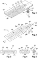
- the light element 100 comprises a substrate 200, a transparency element 400 and an optical fiber film 300 sealed between the substrate 200 and the transparency element 400.
- This light element 100 is designed to be placed on a vehicle bodywork part.
- Mainly exterior parts such as chrome strips running along the side of the vehicle, sill protectors, brand logo, door handle covers, or mirror hulls. This list is not limiting and the light element can be placed on other body elements of the vehicle.
- the optical fiber ply 300 here constituted of a plurality of optical fibers 370 is encapsulated in the light element. It comprises several different parts. Firstly, a connector 330 which is capable of being connected to a light source (not shown) which allows light to be fed to the sheet 300. Next, a passive zone 320 which allows the conduction of light towards an active area 310 The passive zone 320 here forms a strand 340. A strand is understood to mean an area where the fibers 370 are compactly gathered to form a circular section arrangement. In the active zone 310, the fibers 370 are organized into flat-shaped sheets. In this embodiment, the fibers 370 are part of a fabric. This fabric facilitates the handling of the web prior to bonding it to the substrate 200.
- the active zone 310 of the ply of optical fibers 300 is able to diffuse the light that reaches it from the passive zone 320 of the web 300. It is therefore this part that will emit the light of the light element 100.
- the sheet 300 forms a transition zone 350 between the strand 340 and the active area 310. In this transition zone 350, the fibers 370 gather progressively from the active zone 310 to the strand 340.
- a sheath 360 surrounds the sheet 300 from the transition zone 350, in the part where it is still encapsulated between the substrate 200 and the transparency element 400, until the connectivity of the sheet 330, surrounding the passage 340 strand.
- the luminous element 100 consists successively of a foam 210, rendered adhesive by the presence of an adhesive layer (not shown here) on its non-rigid surface, which forms the substrate 200, of a sheet of optical fibers 300 as described above, and a transparency element 400.
- the adhesive foam 210 is a compressible foam pierced with an opening 380 which is here a slot (not shown in this figure) which allows the passage of the transition zone 350
- the foam has a thickness of preferably between 1 and 3 millimeters.
- the adhesive layer is disposed on the surface of the foam facing the transparency element 400 and the active zone of the optical fiber ply 310.
- the transparency element 400 is placed on the surface of the bodywork element (not shown). This element 400 is able to pass the light emitted by the active part of the ply of optical fibers 310.
- the substrate 200 and the transparency element 400 are in direct contact and adhere continuously all around the active area 310 of the optical fiber web 300.
- the slot 380 of the substrate 200 includes to it the sheath 360 at the place where the sheet comes out of the encapsulated portion of the sheet 300.
- the foam 210 adheres through the adhesive layer to the sheath 360 all around the slot 380.
- This arrangement of the light element 100 allows a good encapsulation of the active part of the sheet 310.
- the sealing of the encapsulated portion of the sheet 300 is ensured. It is particularly waterproof, but can also provide a seal to other substances.
- the light element 100 is able to adhere to a bodywork part, for example by means of the transparency element 400 which is fixed thereto.
- the transparency element 400 is fixed on the bodywork part, for example in a housing or an opening in the room.
- the substrate 200, onto which the optical fiber ply 300 has previously been bonded is adhered to the transparency element 400.
- the entire luminous element is fixed on the bodywork part.
- the same luminous element 100 can adapt to several housings of body parts of different shapes.
- the light source can be placed at a distance from the outer surface of the bodywork part.
- the light source is spared.
- the strand shape 340 of the passive zone 320 is particularly advantageous since it enables the sheet to be changed in all directions of space. Thus, it can follow a path, even crooked, arranged in the bodywork part, or other parts of the vehicle, between the location where the light element and the place where the light source is located.
- this form of strand makes it possible to transmit the light over a greater distance than with a conventional sheet.
- the light source can be at a distance of up to three meters from the active area of the optical fiber web 310, contrary to a distance of the order of 45 centimeters usually.
- the figure 2 is a perspective view of a sheet of optical fibers for a light element according to the invention. These elements will not be presented again here.
- This sheet 300 has the same elements as those of the sheet present in figure 1 .
- the sheath 360 surrounds the entire strand 340, as well as the entire transition zone 350 and stops at the beginning of the active zone 310 of the ply.
- the figure 3 which is the following view section aa of the figure 2 , illustrates the organization of the optical fibers 370 at the beginning of the transition zone 350. It can be seen that the fibers are here arranged such that they still adopt a planar shape in their entirety, which is similar to that of the active zone of the web 310, with the warp or weft of the fabric 375 which holds these fibers in position.
- the sheath 360 includes the sheet 300 over its entire contour.
- the figure 4 which is the next view section bb of the figure 2 , illustrates the organization of the optical fibers 370 in the middle of the transition zone 350. It can be seen that there is no more warp or weft of fabric and that the fibers here begin to gather and become entangled to approach the shape that will have the strand 340.
- the sheath 360 includes the ply 300 over its entire contour.
- the figure 5 which is the next view section bb of the figure 2 , illustrates the organization of the optical fibers 370 at the boundary of the transition zone 350 and the strand 340.
- the fibers are completely entangled and the section of the sheet is circular.
- the sheath 360 includes the sheet 300 over its entire contour. When it borrows this form of strand, the sheet 300 is able to extend in any direction of space, as we have previously described.
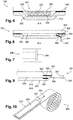
- the figure 6 is a section along the plane aa of the tablecloth of the figure 2 , but this time integrated in the luminous element 100.
- the fiber web 300 is encapsulated between the substrate 200 on the one hand and the transparency element 400 on the other hand.
- Substrate 200 here forms a housing 220 around web 300 to encapsulate it.
- the substrate 200 is in contact with the transparency element 400 on the edges of the sheet 300, and this over the entire contour of the active zone of the optical fiber ply 310.
- the substrate comprises an adhesive layer 500 disposed opposite the transparency element 400. This layer may for example be a double-sided adhesive.
- the substrate 200 also comprises a foam 210 which encapsulates the sheet of optical fibers 300.
- This arrangement makes it possible to seal the encapsulated zone containing the active zone of the optical fiber ply 300 by preventing a substance, for example water, coming from the outside from penetrating through the interface between the substrate. 200 and the transparency element 400.
- the figure 7 is a bottom view of the substrate. This view has a slot 380 in the adhesive foam 210 allowing passage of the transition zone of the sheet 350 in the foam. It is preferentially at the level of the cutting plane AA of the figure 2 that the web passes into the slot 380, which is as long as the web is wide at this location. The sheet is surrounded by sheath 360 at this location.
- the output of the sheet 300 by a slot 380 of the same size as the sheet allows a good encapsulation thereof.
- the slot follows and completely follows the shape of the sheet 300, and adheres to the sheath 360. This structure ensures a good seal of the encapsulated portion of the light element 100 at the outlet of the sheet 300.
- the figure 8 is a sectional view along the plane DD (visible in figure 2 ) of the luminous element 100 of the figure 6 . It can be seen in this view that the slot 380 surrounds the web 300. An adhesive layer 500 is disposed between the adhesive foam 210 and the transition zone 350 of the web at the slot 380. It may be noted that at the level of this zone, the sheet 300 is still surrounded by sheath 360.
- sealing is provided at the outlet of the sheet 300 of the encapsulated area of the light element 100 because the foam conforms to the shape of the sheet and adheres thereto.
- the figure 9 is a section along the DD plane of the figure 2 a light element according to another embodiment of the invention.
- This embodiment differs only from the previous embodiment in that the substrate 200 here does not have a slot for the passage of the sheet 300. Thus, at the outlet of the sheet 300 of the encapsulated area, this is in contact with the transparency element 400 above and with the substrate 200 below and on the sides of the web. An adhesive layer 500 is disposed between the web 300 and the transparency element 400 on the one hand, and between the web and the foam 210 on the other go.
- the substrate 200 is in contact with the transparency element 400 over the entire contour of the web 300, with the exception of the edge through which the transition zone 350 extends to then become the strand 340.
- the substrate 200 forms a housing 220 around the web 300 which matches the shape thereof.
- the sealing at the outlet of the sheet of the encapsulated zone is ensured by the adhesion of the foam 210 on the sheath 360 of the sheet 300 and on the transparency element 400 on the one hand, and by the adhesion between the sheath 360 and the transparency element on the other hand.
- the manufacture of the light element 100 according to this embodiment is facilitated by the fact that it does not require the development of a slot in the substrate in which one would slip the sheet 300; the number of manufacturing steps is therefore reduced.
- the figure 10 is a perspective view of an adhesive foam roll 600 on which is glued a sheet of optical fibers 300.
- This figure shows a particular step of the manufacture of a light element 100 according to the invention.
- the ply 300 is adhered to the adhesive foam roll 500.
- the ply is cut to the desired length in order to then glue it onto a transparency element 400 not shown here. It is possible to cut a slot 380 in the foam at the transition zone of the sheet 350, to obtain a luminous element such as that presented in FIG. figure 6 to 8 . It is also possible to simply cut the foam without slitting it to obtain a luminous element 100 such as the embodiment shown in FIG. figure 9 .
- the size of the sheet 300 it is easy to obtain light elements 100 of different sizes.
- the flexibility of the device and the ability of the foam to catch the gaps between a bodywork part and the light element 100 make the element very easy to adapt to a bodywork part. It is thus possible, with a small number of parts, to achieve a light element 100 that can accommodate a wide variety of body parts shapes.
- a second adhesive layer may for example be placed on the adhesive foam. This layer is thus disposed on the face of the foam which is opposite to the ply of optical fibers. This arrangement allows better adhesion of the light element on the bodywork part.
- the opening allowing the passage of the sheet through the substrate is in the form of a round or oblong hole, instead of being in the form of a slot as shown in the figures.
- the substrate may also include, in place of or in addition to the foam, an elastomer, a polymeric material filled with elastomer.
- an elastomer a polymeric material filled with elastomer.
- it may advantageously have a thickness of between 1 and 3 millimeters.
- the substrate may also include, instead of or in addition to the foam, a metal foil.
- This metal sheet may preferably have a thickness of less than 0.5 millimeters. This sheet is able to match the relief of a bodywork part.
- the substrate may advantageously protrude at the edges of the transparency element.
- the substrate adheres to both the transparency element and the body part on which the element is fixed. This arrangement enhances the adhesion of the light element to the bodywork part.
- the light element is able to adhere to a vehicle bodywork part via the surface of the substrate which is not in contact with the optical fiber sheet.
- the substrate being compressible, it adapts optimally to the surface of the bodywork element on which it is placed. Thus, it can make up any games between the light element 100 and the surface of the bodywork part on which the light element is placed.
Landscapes
- Engineering & Computer Science (AREA)
- General Engineering & Computer Science (AREA)
- Non-Portable Lighting Devices Or Systems Thereof (AREA)
- Light Guides In General And Applications Therefor (AREA)
Applications Claiming Priority (1)
| Application Number | Priority Date | Filing Date | Title |
|---|---|---|---|
| FR1756195A FR3068316A1 (fr) | 2017-06-30 | 2017-06-30 | Element lumineux etanche pour piece de carrosserie de vehicule |
Publications (1)
| Publication Number | Publication Date |
|---|---|
| EP3421877A1 true EP3421877A1 (de) | 2019-01-02 |
Family
ID=60138478
Family Applications (1)
| Application Number | Title | Priority Date | Filing Date |
|---|---|---|---|
| EP18179447.0A Withdrawn EP3421877A1 (de) | 2017-06-30 | 2018-06-25 | Dichtes leuchtelement für ein fahrzeugkarosserie-teil |
Country Status (2)
| Country | Link |
|---|---|
| EP (1) | EP3421877A1 (de) |
| FR (1) | FR3068316A1 (de) |
Cited By (3)
| Publication number | Priority date | Publication date | Assignee | Title |
|---|---|---|---|---|
| FR3101824A1 (fr) * | 2019-10-15 | 2021-04-16 | Compagnie Plastic Omnium Se | Encapsulation d’un tissu lumineux disposé sur une paroi par injection d’un matériau thermodurcissable |
| EP4556315A1 (de) * | 2023-11-20 | 2025-05-21 | Motherson Innovations Company Limited | Verfahren zum befestigen einer beleuchtungsvorrichtung an einem textil, textil für ein fahrzeuginnenteil |
| US12498093B2 (en) * | 2021-08-23 | 2025-12-16 | Bayerische Motoren Werke Aktiengesellschaft | Component for a transportation device, transportation device, and method for producing the component |
Citations (5)
| Publication number | Priority date | Publication date | Assignee | Title |
|---|---|---|---|---|
| DE10214503A1 (de) * | 2002-04-02 | 2003-10-30 | Kastriot Merlaku | Blinklicht-System für Fahrzeuge |
| WO2008011558A2 (en) * | 2006-07-20 | 2008-01-24 | Int America, Llc. | Fiber optic auxiliary lighting system |
| EP2028046A1 (de) * | 2007-08-22 | 2009-02-25 | CCL Design GmbH | Dekorationskörper |
| FR2997354A1 (fr) * | 2012-10-26 | 2014-05-02 | Faurecia Interieur Ind | Ensemble d'eclairage et structure interieure eclairee pour vehicule |
| DE102014221080A1 (de) * | 2014-10-16 | 2016-04-21 | Johnson Controls Interiors Management Gmbh | Innenausstattungsteil für kraftfahrzeuge |
-
2017
- 2017-06-30 FR FR1756195A patent/FR3068316A1/fr not_active Withdrawn
-
2018
- 2018-06-25 EP EP18179447.0A patent/EP3421877A1/de not_active Withdrawn
Patent Citations (5)
| Publication number | Priority date | Publication date | Assignee | Title |
|---|---|---|---|---|
| DE10214503A1 (de) * | 2002-04-02 | 2003-10-30 | Kastriot Merlaku | Blinklicht-System für Fahrzeuge |
| WO2008011558A2 (en) * | 2006-07-20 | 2008-01-24 | Int America, Llc. | Fiber optic auxiliary lighting system |
| EP2028046A1 (de) * | 2007-08-22 | 2009-02-25 | CCL Design GmbH | Dekorationskörper |
| FR2997354A1 (fr) * | 2012-10-26 | 2014-05-02 | Faurecia Interieur Ind | Ensemble d'eclairage et structure interieure eclairee pour vehicule |
| DE102014221080A1 (de) * | 2014-10-16 | 2016-04-21 | Johnson Controls Interiors Management Gmbh | Innenausstattungsteil für kraftfahrzeuge |
Cited By (3)
| Publication number | Priority date | Publication date | Assignee | Title |
|---|---|---|---|---|
| FR3101824A1 (fr) * | 2019-10-15 | 2021-04-16 | Compagnie Plastic Omnium Se | Encapsulation d’un tissu lumineux disposé sur une paroi par injection d’un matériau thermodurcissable |
| US12498093B2 (en) * | 2021-08-23 | 2025-12-16 | Bayerische Motoren Werke Aktiengesellschaft | Component for a transportation device, transportation device, and method for producing the component |
| EP4556315A1 (de) * | 2023-11-20 | 2025-05-21 | Motherson Innovations Company Limited | Verfahren zum befestigen einer beleuchtungsvorrichtung an einem textil, textil für ein fahrzeuginnenteil |
Also Published As
| Publication number | Publication date |
|---|---|
| FR3068316A1 (fr) | 2019-01-04 |
Similar Documents
| Publication | Publication Date | Title |
|---|---|---|
| CA2461341C (fr) | Procede pour fabriquer une vitre en matiere plastique avec une structure de conducteurs electriques et vitre en matiere plastique avec fils noyes | |
| EP2743786B1 (de) | Tragbare elektronische Vorrichtung und Herstellungsverfahren einer solchen Vorrichtung | |
| FR3046387A1 (fr) | Element de carroserie retroeclaire | |
| CA3057605A1 (fr) | Vitrage eclairant | |
| EP1566686A1 (de) | Hintergrundbeleuchtungsvorrichtung für Anzeigeelement | |
| FR2991936A1 (fr) | Element de garnissage retroeclaire au moyen d'un element de support translucide | |
| WO2009156630A1 (fr) | Elément d'habillage intérieur lumineux, porte et véhicule automobile correspondants | |
| FR2912095A1 (fr) | Element a motif decoratif lumineux,et piece d'habillage interieur d'automobile le comportant | |
| FR3077251A1 (fr) | Habillage de vehicule comprenant un ecran d'affichage et procede de fabrication | |
| FR3068316A1 (fr) | Element lumineux etanche pour piece de carrosserie de vehicule | |
| EP3299219A1 (de) | Leuchtvorrichtung, die eine oled lichtquelle umfasst | |
| EP2691800A2 (de) | Beleuchtungsmodul mit verbesserter beleuchtungsuniformität | |
| FR2917350A1 (fr) | Structure interieure de vehicule automobile comportant un affichage sous peau et procede de fabrication d'une telle structure. | |
| EP2145796B1 (de) | Inneres Verkleidungspaneel für Kraftfahrzeug mit rückseitig beleuchteter Zone vereinfachter Ausführung | |
| EP4540054B1 (de) | Glasanordnung für ein kraftfahrzeug und zugehöriges herstellungsverfahren | |
| EP3802181B1 (de) | Signalanordnung für ein türblatt und entsprechende tür und transportfahrzeug | |
| EP3899361B1 (de) | Lichtelement für karosseriebauteil aus spritzgegossenem polycarbonat | |
| FR3105349A1 (fr) | Dispositif d’éclairage et/ou de signalisation comprenant une pluralité d'éléments opaques. | |
| EP4414216A1 (de) | Verkleidungsplatte für ein kraftfahrzeug mit lichtübertragungsbereich und maskierungsbereich | |
| FR2991937A1 (fr) | Element de garnissage comprenant une couche de decor translucide retroeclairee | |
| FR2643028A1 (fr) | Cassette a miroir, notamment pour pare-soleil d'un habitacle d'automobile et procede de fabrication | |
| WO2024141675A1 (fr) | Organe de protection extérieure pour un capteur extérieur d'un véhicule | |
| FR3087169A1 (fr) | Ensemble pour vehicule automobile comprenant un tissu eclairant | |
| FR2980131A1 (fr) | Element tisse comprenant une partie peripherique enrobee dans un materiau de moulage | |
| EP1566687B1 (de) | Hintergrundbeleuchtungsvorrichtung für Anzeigeelement |
Legal Events
| Date | Code | Title | Description |
|---|---|---|---|
| PUAI | Public reference made under article 153(3) epc to a published international application that has entered the european phase |
Free format text: ORIGINAL CODE: 0009012 |
|
| STAA | Information on the status of an ep patent application or granted ep patent |
Free format text: STATUS: THE APPLICATION HAS BEEN PUBLISHED |
|
| AK | Designated contracting states |
Kind code of ref document: A1 Designated state(s): AL AT BE BG CH CY CZ DE DK EE ES FI FR GB GR HR HU IE IS IT LI LT LU LV MC MK MT NL NO PL PT RO RS SE SI SK SM TR |
|
| AX | Request for extension of the european patent |
Extension state: BA ME |
|
| STAA | Information on the status of an ep patent application or granted ep patent |
Free format text: STATUS: REQUEST FOR EXAMINATION WAS MADE |
|
| 17P | Request for examination filed |
Effective date: 20190702 |
|
| RBV | Designated contracting states (corrected) |
Designated state(s): AL AT BE BG CH CY CZ DE DK EE ES FI FR GB GR HR HU IE IS IT LI LT LU LV MC MK MT NL NO PL PT RO RS SE SI SK SM TR |
|
| STAA | Information on the status of an ep patent application or granted ep patent |
Free format text: STATUS: THE APPLICATION HAS BEEN WITHDRAWN |
|
| 18W | Application withdrawn |
Effective date: 20200713 |