EP3421900B1 - Système d'alimentation en eau chaude du type à accumulation - Google Patents
Système d'alimentation en eau chaude du type à accumulation Download PDFInfo
- Publication number
- EP3421900B1 EP3421900B1 EP16891397.8A EP16891397A EP3421900B1 EP 3421900 B1 EP3421900 B1 EP 3421900B1 EP 16891397 A EP16891397 A EP 16891397A EP 3421900 B1 EP3421900 B1 EP 3421900B1
- Authority
- EP
- European Patent Office
- Prior art keywords
- hot water
- temperature
- heat exchanger
- heat
- heating medium
- Prior art date
- Legal status (The legal status is an assumption and is not a legal conclusion. Google has not performed a legal analysis and makes no representation as to the accuracy of the status listed.)
- Not-in-force
Links
Images

Classifications
-
- F—MECHANICAL ENGINEERING; LIGHTING; HEATING; WEAPONS; BLASTING
- F24—HEATING; RANGES; VENTILATING
- F24D—DOMESTIC- OR SPACE-HEATING SYSTEMS, e.g. CENTRAL HEATING SYSTEMS; DOMESTIC HOT-WATER SUPPLY SYSTEMS; ELEMENTS OR COMPONENTS THEREFOR
- F24D19/00—Details
- F24D19/10—Arrangement or mounting of control or safety devices
- F24D19/1006—Arrangement or mounting of control or safety devices for water heating systems
- F24D19/1051—Arrangement or mounting of control or safety devices for water heating systems for domestic hot water
- F24D19/1054—Arrangement or mounting of control or safety devices for water heating systems for domestic hot water the system uses a heat pump
-
- F—MECHANICAL ENGINEERING; LIGHTING; HEATING; WEAPONS; BLASTING
- F24—HEATING; RANGES; VENTILATING
- F24D—DOMESTIC- OR SPACE-HEATING SYSTEMS, e.g. CENTRAL HEATING SYSTEMS; DOMESTIC HOT-WATER SUPPLY SYSTEMS; ELEMENTS OR COMPONENTS THEREFOR
- F24D17/00—Domestic hot-water supply systems
- F24D17/02—Domestic hot-water supply systems using heat pumps
-
- F—MECHANICAL ENGINEERING; LIGHTING; HEATING; WEAPONS; BLASTING
- F24—HEATING; RANGES; VENTILATING
- F24H—FLUID HEATERS, e.g. WATER OR AIR HEATERS, HAVING HEAT-GENERATING MEANS, e.g. HEAT PUMPS, IN GENERAL
- F24H4/00—Fluid heaters characterised by the use of heat pumps
- F24H4/02—Water heaters
- F24H4/04—Storage heaters
Definitions
- the present invention relates to a storage type hot water supplying system.
- Hot water supplying systems are known e.g. from documents US 2014/0291411 A1 , EP 1 780 476 A1 , JP 2013 036648 A and JP S61 29649 A .
- a storage type hot water supplying system according to the preamble of claim 1 is known from the patent US20014/0291411A1 .
- a known storage type hot water supplying system includes a heat pump configured to heat a heating medium, a heat exchanger configured to exchange heat between the heated heating medium and water, and a hot water storage tank configured to store the heated hot water (for example, see PTL 1).
- the rotational speed of a first pump (13) is adjusted so that the temperature of a heating medium flowing out of a first heat exchanger (11) of the heat pump becomes equal to a first temperature higher than a heat storage temperature set in advance.
- the rotational speed of a second pump (22) is adjusted so that the temperature of hot water flowing out of a second heat exchanger (16) becomes equal to the abovementioned heat storage temperature.
- the heat exchange capacity of the heat exchanger configured to exchange heat between the heating medium and the water decreases over time. This is due to the deposition of scale, for example.
- the conventional system described above has the following problem.
- the heat exchange capacity of the second heat exchanger (16) decreases over time, the temperature of the hot water flowing out of the second heat exchanger (16) decreases if the circulation flow rate of the water remains constant.
- the rotational speed of the second pump (22) is reduced, and the circulation flow rate of the water decreases.
- the circulation flow rate of the water decreases, the temperature of the heating medium returning from the second heat exchanger (16) to the first heat exchanger (11) of the heat pump rises.
- the rise in the temperature of the heating medium flowing into the first heat exchanger (11) of the heat pump degrades energy efficiency, for example, decreases the coefficient of performance.
- the present invention has been made in order to solve the abovementioned problem, and an object thereof is to provide a storage type hot water supplying system capable of reducing the degradation in energy efficiency even when the heat exchange capacity of the heat exchanger decreases over time.
- a storage type hot water supplying system includes: heating means for heating a heating medium; a heat exchanger configured to exchange heat between the heating medium and water; a hot water storage tank configured to store hot water heated in the heat exchanger; a first pump configured to circulate the heating medium in a first circuit connecting the heat exchanger and the heating means to each other; a second pump configured to circulate water in a second circuit connecting the heat exchanger and the hot water storage tank to each other; and control means for controlling the first pump and the second pump.
- the first pump is controlled so that a temperature of the heating medium heated by the heating means becomes equal to a target temperature
- the second pump is controlled so that a water temperature difference that is a difference between a temperature of the hot water heated in the heat exchanger and a temperature of the water before being heated in the heat exchanger becomes equal to a heating medium temperature difference that is a difference between the temperature of the heating medium heated by the heating means and a temperature of the heating medium before being heated by the heating means.
- the degradation in the energy efficiency can be reduced even when the heat exchange capacity of the heat exchanger decreases over time.
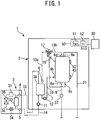
- Fig. 1 illustrates a storage type hot water supplying system of a first embodiment.
- a storage type hot water supplying system 1 of this embodiment includes a tank unit 2, a heat pump device 3, a control device 50, and a remote controller 60.
- the tank unit 2 includes a hot water storage tank 8.
- the heat pump device 3 is an example of heating means for heating a heating medium.
- the control device 50 is an example of control means for controlling the operation of the storage type hot water supplying system 1.
- the remote controller 60 is an example of a user interface. The remote controller 60 can receive user operation such as a command for operation and the change of set values.
- the tank unit 2 and the heat pump device 3 are connected to each other via a conduit 14, a conduit 15, and electric wiring (not shown).
- the tank unit 2 may be placed indoors or may be placed outdoors.
- the heat pump device 3 may be placed outdoors.
- the remote controller 60 may be installed in a room.
- control device 50 is installed in the tank unit 2.
- actuators such as a valve, a pump, and a compressor and various kinds of sensors included in the storage type hot water supplying system 1 are electrically connected to the control device 50.
- the remote controller 60 is connected to the control device 50 through wired or wireless connection such that bi-directional data communication is possible.
- the remote controller 60 may include a display configured to display information such as the state of the storage type hot water supplying system 1, an operation unit such as a button to be operated by a user, and a voice output device configured to provide voice guide.
- the heat pump device 3 includes a refrigerant circuit.
- the refrigerant circuit includes a compressor 31, a heat exchanger 33, a decompression device 34, an evaporator 36, and a refrigerant pipe 35 annularly connecting those elements to each other.
- the heat exchanger 33 exchanges heat between a high-pressure and high-temperature refrigerant compressed by the compressor 31 and a liquid heating medium.
- the heating medium may be water or may be brine other than water such as calcium chloride solution, ethylene glycol solution, and alcohol.
- the decompression device 34 expands and decompress the high-pressure refrigerant that has passed through the heat exchanger 33.
- the decompression device 34 may be an expansion valve capable of changing the opening degree thereof.
- the evaporator 36 evaporates the low-pressure refrigerant that has passed through the decompression device 34.
- the fluid of which heat is exchanged with the refrigerant in the evaporator 36 may be air, ground water, waste water, or solar water, for example.
- the heat pump device 3 may include a fan or a pump (not shown) configured to send the fluid to the evaporator 36.
- the heat pump device 3 may be able to change the heating power [kW].
- the heating power is a quantity of heat provided to the heating medium by the heat pump device 3 per unit of time.
- the control device 50 may change the heating power of the heat pump device 3 by changing the capacity of the compressor 31.
- the control device 50 may change the capacity of the compressor 31 by changing the rotational speed of the compressor 31.
- the control device 50 may change the rotational speed of the compressor 31 by inverter control, for example.
- the hot water storage tank 8 stores hot water heated by the heat pump device 3.
- the hot water storage tank 8 is covered by a heat insulating material (not shown). Thermal stratification in which the temperature of the upper layer is high and the temperature of the lower layer is low can be formed in the hot water storage tank 8 due to the density difference in water depending on the temperature.
- An inlet 8a provided in the lower portion of the hot water storage tank 8 is connected to a water supply pipe 9. Water supplied from a water source such as water supply is decompressed to a predetermined pressure by a decompression valve 37, and flows into the hot water storage tank 8 from the inlet 8a through the water supply pipe 9.
- An outlet 8e provided in the upper portion of the hot water storage tank 8 is connected to a hot water supply pipe 21.
- the hot water stored in the hot water storage tank 8 flows from the outlet 8e, and is supplied to the outside of the storage type hot water supplying system 1 through the hot water supply pipe 21.
- the hot water storage tank 8 is maintained in a full state by causing the same amount of water as the hot water that has flowed out to the hot water supply pipe 21 to flow into the hot water storage tank 8 from the water supply pipe 9.
- a plurality of tank temperature sensors 42 and 43 are mounted on the hot water storage tank 8 in positions at different heights.
- the volume of the hot water and the heat storage amount in the hot water storage tank 8 can be detected by detecting the temperature distribution in the hot water storage tank 8 in the vertical direction by the tank temperature sensors 42 and 43.
- the control device 50 may control the start and stop of heat accumulating operation that is the operation of accumulating hot water in the hot water storage tank 8 on the basis of the volume of the hot water or the heat storage amount in the hot water storage tank 8.
- two tank temperature sensors 42 and 43 are installed on the hot water storage tank 8, but three or more tank temperature sensors may be installed on the hot water storage tank 8.
- the tank unit 2 further includes a conduit 10, a first pump 11, a second pump 12, a conduit 13a, a conduit 13b, a conduit 16, a three-way valve 17, and a heat exchanger 38.
- the three-way valve 17 is flow-passage switching means including an a port, a b port, and a c port.
- the heat exchanger 38 exchanges heat between the heating medium heated in the heat pump device 3 and the water.
- the conduit 10 connects an outlet 8b provided in the lower portion of the hot water storage tank 8 and an inlet for water of the heat exchanger 38 to each other.
- the second pump 12 is connected to the conduit 10 at a place midway through the conduit 10.
- the conduit 13a connects an outlet for water of the heat exchanger 38 and the a port of the three-way valve 17 to each other.
- the conduit 13b connects the c port of the three-way valve 17 and an inlet 8d formed in the upper portion of the hot water storage tank 8 to each other.
- the conduit 16 connects the b port of the three-way valve 17 and an inlet 8c formed in the lower portion of the hot water storage tank 8 to each other.
- the inlet 8c is located at a position lower than the outlet 8b.
- the present invention is not limited to such configuration, and the inlet 8c may be located at a position at the same height as the outlet 8b, or the inlet 8c may be located at a position higher than the outlet 8b.
- the conduit 14 connects an outlet for the heating medium of the heat exchanger 38 of the tank unit 2 and an inlet for the heating medium of the heat exchanger 33 of the heat pump device 3 to each other.
- the first pump 11 is connected to the conduit 14 at a place midway through the conduit 14.
- the conduit 15 connects an outlet for the heating medium of the heat exchanger 33 of the heat pump device 3 and an inlet for the heating medium of the heat exchanger 38 of the tank unit 2 to each other.
- the following is performed in the heat accumulating operation.
- the three-way valve 17 is put in a state in which the a port is in communication with the c port, and the b port is shut off.
- the heat pump device 3, the first pump 11, and the second pump 12 are operated.
- the heating medium heated in the heat exchanger 33 of the heat pump device 3 flows into the heat exchanger 38 through the conduit 15.
- the water taken from the outlet 8b of the hot water storage tank 8 flows into the heat exchanger 38 through the conduit 10.
- the heating medium heats the water. That is, the heating medium is cooled by the water.
- the heating medium cooled in the heat exchanger 38 returns to the heat exchanger 33 through the conduit 14.
- the hot water heated in the heat exchanger 38 flows into the hot water storage tank 8 from the inlet 8d through the conduit 13a, the three-way valve 17, and the conduit 13b. Hot water is accumulated in the hot water storage tank 8 from the top to the bottom by circulating the heating medium and the water as above.
- a first circuit connecting the heat exchanger 38 and the heat pump device 3 to each other is formed by the conduit 14 and the conduit 15.
- a second circuit connecting the heat exchanger 38 and the hot water storage tank 8 to each other is formed by the conduit 10, the conduit 13a, the three-way valve 17, and the conduit 13b.
- the control device 50 can change the flow rate of the heating medium flowing in the first circuit by controlling the capacity of the first pump 11.
- the rotational speed of the first pump 11 may be variable.
- the first pump 11 may include a pulse width modulation control type DC motor that can change the rotational speed by a speed command voltage from the control device 50.
- the control device 50 can change the flow rate of the water flowing in the second circuit by controlling the capacity of the second pump 12.
- the rotational speed of the second pump 12 may be variable.
- the second pump 12 may include a pulse width modulation control type DC motor that can change the rotational speed by a speed command voltage from the control device 50.
- a first temperature sensor 4 is installed in the conduit 15.
- the first temperature sensor 4 detects the temperature of the heating medium that has been heated by the heat pump device 3, that is, the temperature of the heating medium flowing out of the heat exchanger 33.
- the temperature of the heat medium flowing into the heat exchanger 38 can be detected by the first temperature sensor 4.
- a second temperature sensor 5 is installed in the conduit 14.
- the second temperature sensor 5 detects the temperature of the heating medium before being heated by the heat pump device 3, that is, the temperature of the heating medium flowing into the heat exchanger 33.
- the temperature of the heating medium flowing out of the heat exchanger 38 can be detected by the second temperature sensor 5.
- the first temperature sensor 4 and the second temperature sensor 5 are in the heat pump device 3, but the first temperature sensor 4 and the second temperature sensor 5 may be arranged in the tank unit 2.
- a third temperature sensor 6 is installed in the conduit 13a.
- the third temperature sensor 6 detects the temperature of the hot water flowing out of the heat exchanger 38, that is, the temperature of the hot water that has been heated in the heat exchanger 38.
- a fourth temperature sensor 7 is installed in the conduit 10. The fourth temperature sensor 7 detects the temperature of the water flowing into the heat exchanger 38, that is, the temperature of the water before being heated in the heat exchanger 38.
- the user can set a first hot water supply temperature TH and a second hot water supply temperature TL for the storage type hot water supplying system 1.
- the second hot water supply temperature TL is a temperature lower than the first hot water supply temperature TH.
- the remote controller 60 may be capable of receiving the user operation for setting the first hot water supply temperature TH and the second hot water supply temperature TL.
- the remote controller 60 may transmit information of set values of the first hot water supply temperature TH and the second hot water supply temperature TL that are input into the remote controller 60 by the user to the control device 50.
- the first hot water supply temperature TH may be set as 60°C and the second hot water supply temperature TL may be set as 50°C.
- the control device 50 may set a target temperature Tp1 of the heating medium that has been heated by the heat pump device 3, that is, the heating medium flowing into the heat exchanger 38 in the heat accumulating operation on the basis of the first hot water supply temperature TH.
- the target temperature Tp1 is set to be a temperature higher than the first hot water supply temperature TH.
- the control device 50 may set a value obtained by adding an assumed value ⁇ of a terminal temperature difference of the heat exchanger 38 in the heat accumulating operation to the first hot water supply temperature TH as the target temperature Tp1.
- the terminal temperature difference is a difference between the temperature of the heating medium flowing into the heat exchanger 38 and the temperature of the hot water flowing out of the heat exchanger 38.
- the target temperature Tp1 may set as 70°C. In this way, the following is obtained.
- the temperature of the hot water flowing out of the heat exchanger 38 becomes equal to the first hot water supply temperature TH.
- the hot water of which temperature is equal to the first hot water supply temperature TH is accumulated in the hot water storage tank 8.
- the hot water of which temperature is equal to the first hot water supply temperature TH set by the user can be supplied from the hot water storage tank 8 to the outside through the hot water supply pipe 21.
- the temperature in the hot water storage tank 8 decreases by supplying hot water to the hot water supply pipe 21 from the hot water storage tank 8 and dissipating heat from the hot water storage tank 8 to the surroundings.
- the control device 50 may start the heat accumulating operation with the detection as a trigger.
- the control device 50 adjusts the capacity of the first pump 11 so that a temperature Tout1 of the heating medium that has been heated by the heat pump device 3, that is, the temperature Tout1 detected by the first temperature sensor 4 becomes equal to the target temperature Tp1.
- the capacity of the first pump 11 is reduced, the flow rate of the heating medium flowing in the first circuit decreases, and the temperature Tout1 increases.
- the capacity of the first pump 11 is increased, the flow rate of the heating medium flowing in the first circuit increases, and the temperature Tout1 decreases.
- the control device 50 may adjust the capacity of the first pump 11 on the basis of the deviation between the target temperature Tp1 and the temperature Tout1. With use of the deviation, the control device 50 may adjust the capacity of the first pump 11 on the basis of proportional control, integral control, differential control, or the combination of two or three of the above.
- the control device 50 can obtain the value of the heating medium temperature difference ⁇ T1 on the basis of the temperatures detected by the first temperature sensor 4 and the second temperature sensor 5.
- the control device 50 can obtain the value of the water temperature difference ⁇ T2 on the basis of the temperatures detected by the third temperature sensor 6 and the fourth temperature sensor 7.
- the control device 50 adjusts the capacity of the second pump 12 so that the water temperature difference ⁇ T2 becomes equal to the heating medium temperature difference ⁇ T1. That is, the second pump 12 is controlled so that the following expression is satisfied.
- the control device 50 may adjust the capacity of the second pump 12 on the basis of the deviation between the heating medium temperature difference ⁇ T1 and the water temperature difference ⁇ T2. With use of the deviation, the control device 50 may adjust the capacity of the second pump 12 on the basis of proportional control, integral control, differential control, or the combination of two or three of the above.
- the heat exchange capacity of the heat exchanger 38 decreases over time. This is due to the deposition of scale, for example. Scale is thought to be mineral components contained in water such as calcium ion and magnesium ion that have deposited and adhered as carbonate crystals.
- the terminal temperature difference of the heat exchanger 38 increases over time.
- the initial terminal temperature difference of the heat exchanger 38 is referred to as ⁇
- the increase over time is referred to as ⁇ .
- the increase ⁇ of the terminal temperature difference of the heat exchanger 38 over time may increase at a rate of about 1°C/year depending on the quality of the water.
- the first pump 11 is controlled so that the temperature Tout1 of the heating medium flowing into the heat exchanger 38 becomes equal to the target temperature Tp1.
- Temperature Tout 1 Target temperature Tp 1
- the hot water storage temperature of the hot water storage tank 8 immediately after the heat accumulating operation can be assumed to be equal to the temperature Tout2 of the hot water that has been heated in the heat exchanger 38.
- the hot water storage temperature of the hot water storage tank 8 immediately after the heat accumulating operation is referred to as the hot water storage temperature Tout2.
- the temperature Tout2 of the hot water that has been heated in the heat exchanger 38 is a value obtained by subtracting the terminal temperature difference of the heat exchanger 38 from the temperature Tout1 of the heating medium flowing into the heat exchanger 38, that is, the target temperature Tp1.
- the initial terminal temperature difference of the heat exchanger 38 is ⁇ .
- Hot water storage temperature Tout2 Target temperature Tp 1 ⁇ ⁇ + ⁇
- the hot water storage temperature Tout2 decreases by the increase ⁇ of the terminal temperature difference of the heat exchanger 38 over time from the initial temperature.
- the water temperature difference ⁇ T2 decreases by ⁇ in accordance with the expression (2) described above.
- the heat exchange amount in the heat exchanger 38 decreases, and hence the temperature Tin1 of the heating medium flowing out of the heat exchanger 38 increases.
- the temperature Tout1 is maintained at a value equal to the target temperature Tp1 in accordance with the expression (4) described above.
- the heating medium temperature difference ⁇ T1 decreases in accordance with the expression (1) described above.
- the heating medium temperature difference ⁇ T1 also decreases by ⁇ .
- the temperature Tin1 of the heating medium before being heated by the heat pump device 3 increases by ⁇ from the state before the heat exchange capacity of the heat exchanger 38 decreases over time.
- the capacity of the second pump 12 is adjusted so that the temperature Tout2 of the hot water flowing out of the heat exchanger 38 becomes equal to the target hot water storage temperature Tp.
- the flow rate of the water flowing in the second circuit needs to be reduced in order to maintain the temperature Tout2 of the hot water flowing out of the heat exchanger 38 at the target hot water storage temperature Tp.
- the capacity of the second pump 12 is reduced.
- the flow rate of the water flowing in the second circuit needs to be lower than that in this embodiment. Therefore, in the comparative example, the heat exchange amount in the heat exchanger 38 becomes even more lower than this embodiment, and the temperature Tin1 of the heating medium flowing out of the heat exchanger 38, that is, the temperature Tin1 of the heating medium before being heated by the heat pump device 3 rises even more than that in this embodiment. In the comparative example, the increase in the temperature Tin1 from the state before the heat exchange capacity of the heat exchanger 38 has decreased over time is larger than ⁇ .
- the energy efficiency for example, the coefficient of performance of the heat pump device 3 becomes lower as the temperature Tin1 of the heating medium before being heated by the heat pump device 3 becomes higher.
- the increase in the temperature Tin1 as the heat exchange performance of the heat exchanger 38 decreases over time can be smaller than that in the comparative example.
- the decrease in the energy efficiency for example, the decrease in the coefficient of performance of the heat pump device 3 when the heat exchange performance of the heat exchanger 38 decreases over time can be smaller than that of the comparative example.
- the temperature Tout2 of the hot water flowing out of the heat exchanger 38 in the heat accumulating operation decreases in accordance with the decrease in the heat exchange performance of the heat exchanger 38 over time.
- the second pump 12 be controlled so that the water temperature difference ⁇ T2 becomes equal to the heating medium temperature difference ⁇ T1 even when the temperature Tout2 of the hot water flowing out of the heat exchanger 38 in the heat accumulating operation does not reach the set value of the first hot water supply temperature TH. In this manner, the decrease in the energy efficiency of the heat pump device 3 can be reduced more reliably even when the heat exchange performance of the heat exchanger 38 decreases over time.
- the energy efficiency of the heat pump device 3 becomes lower.
- the target temperature Tp1 of the heating medium heated by the heat pump device 3 be increased when the temperature Tout2 of the hot water flowing out of the heat exchanger 38 in the heat accumulating operation does not reach the set value of the second hot water supply temperature TL.
- the temperature of the hot water stored in the hot water storage tank 8 is prevented from becoming lower than the set value of the second hot water supply temperature TL.
- the hot water of which temperature is the second hot water supply temperature TL set by the user can be reliably supplied from the hot water storage tank 8.
- the control device 50 may limit the upper limit of the target temperature Tp1 of the heating medium heated by the heat pump device 3 in the heat accumulating operation. For example, the control device 50 may set the upper limit so that the target temperature Tp1 does not exceed 90°C. When the target temperature Tp1 is set too high, the life of the heat pump device 3 can be affected. Bad influence on the life the heat pump device 3 can be reliably prevented by limiting the upper limit of the target temperature Tp1.
- the control device 50 may limit the lower limit of the flow rate of the water flowing in the second circuit in the heat accumulating operation.
- the control device 50 may set a lower limit for the capacity of the second pump 12 so that the flow rate of the water flowing in the second circuit does not fall below 1 L/min.
- the heating power can become insufficient. The heating power can be reliably prevented from becoming insufficient by limiting the lower limit of the flow rate of the water flowing in the second circuit.
- the control device 50 may notify the user of an abnormality.
- the abnormality may be displayed on the display of the remote controller 60, or an audio guide indicating the abnormality may be output from the remote controller 60. The user can be prompted to repair or exchange the heat exchanger 38 by notifying the user of the abnormality.
- the reference value described above may be equal to the set value of the second hot water supply temperature TL.
- the control device 50 may activate the second pump 12 after the heat pump device 3 and the first pump 11 are activated.
- the value of the heating medium temperature difference ⁇ T1 can be unstable immediately after the activation of the heat pump device 3 and the first pump 11.
- the second pump 12 is controlled so that the water temperature difference ⁇ T2 becomes equal to the heating medium temperature difference ⁇ T1 while the value of the heating medium temperature difference ⁇ T1 is unstable, hunting is likely to occur.
- the control stability of the second pump 12 can be enhanced by starting the operation of the second pump 12 after a certain amount of time has passed after the heat pump device 3 and the first pump 11 have been activated and after the value of the heating medium temperature difference ⁇ T1 has been stabilized.
- the operation of the second pump 12 may be started after one minute has passed after the operation of the first pump 11 has started.
- a storage type hot water supplying system 1 of the second embodiment illustrated in Fig. 2 includes a first flow rate sensor 18 and a second flow rate sensor 19.
- the first flow rate sensor 18 is installed in the conduit 15.
- the first flow rate sensor 18 detects the volumetric flow rate of the heating medium flowing in the first circuit.
- the first flow rate sensor 18 may be installed in the conduit 14 instead of the conduit 15.
- the second flow rate sensor 19 is installed in the conduit 10.
- the second flow rate sensor 19 detects the volumetric flow rate of the water flowing in the second circuit.
- the second flow rate sensor 19 may be installed in the conduit 13a or the conduit 13b instead of the conduit 10.
- the control device 50 may adjust the capacity of the second pump 12 so that the volumetric flow rate of the water detected by the second flow rate sensor 19 becomes equal to the volumetric flow rate of the heating medium detected by the first flow rate sensor 18.
- the water temperature difference ⁇ T2 accordingly becomes equal to the heating medium temperature difference ⁇ T1.
- the control device 50 may adjust the capacity of the second pump 12 so that the heat capacity flow rate of the water flowing in the second circuit becomes equal to the heat capacity flow rate of the heating medium flowing in the first circuit.
- the control device 50 may calculate a heat capacity flow rate Cph ⁇ ph ⁇ Vh [kW/K] of the heating medium by multiplying prestored values of a specific heat Cph [kJ/kgK] of the heating medium and a density ph [kg/m 3 ] of the heating medium by a volumetric flow rate Vh [m 3 /second] of the heating medium detected by the first flow rate sensor 18.
- the control device 50 may calculate a heat capacity flow rate Cpw ⁇ ⁇ w ⁇ Vw [kW/K] of the water by multiplying prestored values of a specific heat Cpw [kJ/kgK] of the water and a density pw [kg/m 3 ] of the water by a volumetric flow rate Vw [m 3 /second] of the water detected by the second flow rate sensor 19.
- the heat capacity flow rate of the water flowing in the second circuit becomes equal to the heat capacity flow rate of the heating medium flowing in the first circuit
- the water temperature difference ⁇ T2 accordingly becomes equal to the heating medium temperature difference ⁇ T1.
- an effect similar to that in the first embodiment can be obtained even without using the information detected by the second temperature sensor 5, the third temperature sensor 6, and the fourth temperature sensor 7.
- the storage type hot water supplying system 1 of the second embodiment does not necessarily need to include the second temperature sensor 5, the third temperature sensor 6, and the fourth temperature sensor 7.
- the functions of the control device 50 included in the storage type hot water supplying system 1 of the first embodiment and the second embodiment may be implemented by a processing circuit.
- the processing circuit of the control device 50 includes at least one processor 51 and at least one memory 52.
- the functions of the control device 50 may be implemented by software, firmware, or a combination of software and firmware.
- At least one of the software and the firmware may be described as a program.
- At least one of the software and the firmware may be stored in at least one memory 52.
- At least one processor 51 may implement the functions of the control device 50 by reading and executing a program stored in at least one memory 52.
- At least one memory 52 may include a nonvolatile semiconductor memory or a volatile semiconductor memory, or a magnetic disk.
- the processing circuit of the control device 50 may include at least one dedicated hardware.
- the processing circuit may be, for example, a single circuit, a composite circuit, a programmed processor, a parallel-programmed processor, an ASIC (Application Specific Integrated Circuit), an FPGA (Field-Programmable Gate Array), or a combination of the above.
- Each of the functions of the units of the control device 50 may be implemented by the processing circuit.
- the functions of the units of the control device 50 may be collectively implemented by the processing circuit.
- a part of the functions of the control device 50 may be implemented by dedicated hardware, and other parts of the functions of the control device 50 may be implemented by software or firmware.
- the processing circuit may implement the functions of the control device 50 by hardware, software, firmware, or a combination of the above.
- the present invention is not limited to a configuration in which the operation of the storage type hot water supplying system 1 is controlled by a single control device.
- the present invention may employ a configuration in which the operation of the storage type hot water supplying system 1 is controlled by a plurality of control devices in cooperation with each other.
Landscapes
- Engineering & Computer Science (AREA)
- Physics & Mathematics (AREA)
- Thermal Sciences (AREA)
- Chemical & Material Sciences (AREA)
- Combustion & Propulsion (AREA)
- Mechanical Engineering (AREA)
- General Engineering & Computer Science (AREA)
- Heat-Pump Type And Storage Water Heaters (AREA)
Claims (9)
- Système d'alimentation en eau chaude du type à stockage (1), comprenant :un moyen de chauffage (3) pour chauffer un milieu de chauffage ;un échangeur thermique (38) qui est configuré pour échanger de la chaleur entre le milieu de chauffage et l'eau ;un réservoir de stockage d'eau chaude (8) qui est configuré pour stocker l'eau chaude qui est chauffée à l'intérieur de l'échangeur thermique (38) ;un premier circuit (14, 15) qui connecte l'échangeur thermique (38) et le moyen de chauffage (3) l'un à l'autre ;une première pompe (11) qui est configurée pour faire circuler le milieu de chauffage à l'intérieur du premier circuit (14, 15) ;un second circuit (10, 13a, 13b, 17) qui connecte l'échangeur thermique (38) et le réservoir de stockage d'eau chaude (8) l'un à l'autre ;une seconde pompe (12) qui est configurée pour faire circuler l'eau à l'intérieur du second circuit (10, 13a, 13b, 17) ; etun moyen de commande (50) pour commander la première pompe (11) et la seconde pompe (12),caractérisé en ce que le moyen de commande (50) est configuré de telle sorte que, lors d'une opération d'accumulation de chaleur pour accumuler de l'eau chaude à l'intérieur du réservoir de stockage d'eau chaude (8), la première pompe (11) soit commandée de telle sorte qu'une température du milieu de chauffage qui est chauffé par le moyen de chauffage (3) et qui s'écoule en sortie du moyen de chauffage (3) devienne égale à une température cible, et de telle sorte que la seconde pompe (12) soit commandée de telle sorte qu'une différence de température de l'eau qui est une différence entre une température de l'eau chaude qui est chauffée à l'intérieur de l'échangeur thermique (38) et qui s'écoule en sortie de l'échangeur thermique (38) et une température de l'eau avant qu'elle ne soit chauffée à l'intérieur de l'échangeur thermique (38) et avant qu'elle ne s'écoule à l'intérieur de l'échangeur thermique (38) devienne égale à une différence de température du milieu de chauffage qui est une différence entre la température du milieu de chauffage qui est chauffé par le moyen de chauffage (3) et qui s'écoule en sortie du moyen de chauffage (3) et une température du milieu de chauffage avant qu'il ne soit chauffé par le moyen de chauffage (3) et avant qu'il ne s'écoule à l'intérieur du moyen de chauffage (3).
- Système d'alimentation en eau chaude du type à stockage (1) selon la revendication 1, comprenant en outre un moyen (60) pour recevoir une opération d'utilisateur pour régler une première température d'alimentation en eau chaude et une seconde température d'alimentation en eau chaude qui est plus faible que la première température d'alimentation en eau chaude, dans lequel :la température cible est une température qui est plus élevée qu'une valeur de réglage de la première température d'alimentation en eau chaude ; etle moyen de commande (50) est configuré pour commander la seconde pompe (12) lors de l'opération d'accumulation de chaleur de telle sorte que la différence de température de l'eau devienne égale à la différence de température du milieu de chauffage même lorsque la température de l'eau chaude qui est chauffée à l'intérieur de l'échangeur thermique (38) n'atteint pas la valeur de réglage de la première température d'alimentation en eau chaude.
- Système d'alimentation en eau chaude du type à stockage (1) selon la revendication 2, dans lequel le moyen de commande (50) est configuré de telle sorte que la température cible ne soit pas modifiée même lorsque la température de l'eau chaude qui est chauffée à l'intérieur de l'échangeur thermique (38) n'atteint pas la valeur de réglage de la première température d'alimentation en eau chaude lors de l'opération d'accumulation de chaleur.
- Système d'alimentation en eau chaude du type à stockage (1) selon la revendication 2 ou 3, dans lequel le moyen de commande (50) est configuré pour augmenter la température cible lorsque la température de l'eau chaude qui est chauffée à l'intérieur de l'échangeur thermique (38) n'atteint pas une valeur de réglage de la seconde température d'alimentation en eau chaude lors de l'opération d'accumulation de chaleur.
- Système d'alimentation en eau chaude du type à stockage (1) selon l'une quelconque des revendications 1 à 4, comprenant en outre :un moyen (18) pour détecter un débit d'écoulement du milieu de chauffage qui s'écoule à l'intérieur du premier circuit (14, 15) ; etun moyen (19) pour détecter un débit d'écoulement de l'eau qui s'écoule à l'intérieur du second circuit (10, 13a, 13b, 17),dans lequel le moyen de commande (50) est configuré pour commander la seconde pompe (12) lors de l'opération d'accumulation de chaleur de telle sorte qu'un débit d'écoulement volumétrique ou qu'un débit d'écoulement en termes de capacité thermique de l'eau qui s'écoule à l'intérieur du seconde circuit (10, 13a, 13b, 17) devienne égal à un débit d'écoulement volumétrique ou à un débit d'écoulement en termes de capacité thermique du milieu de chauffage qui s'écoule à l'intérieur du premier circuit (14, 15).
- Système d'alimentation en eau chaude du type à stockage (1) selon l'une quelconque des revendications 1 à 5, dans lequel le moyen de commande (50) est configuré pour limiter une limite supérieure de la température cible lors de l'opération d'accumulation de chaleur.
- Système d'alimentation en eau chaude du type à stockage (1) selon l'une quelconque des revendications 1 à 6, dans lequel le moyen de commande (50) est configuré pour commander les première et seconde pompes (11, 12) de telle sorte que, lorsque l'opération d'accumulation de chaleur est démarrée, la seconde pompe (12) soit activée après que la première pompe (11) est activée.
- Système d'alimentation en eau chaude du type à stockage (1) selon l'une quelconque des revendications 1 à 7, dans lequel le moyen de commande (50) est configuré pour limiter une limite inférieure d'un débit d'écoulement de l'eau qui s'écoule à l'intérieur du second circuit (10, 13a, 13b, 17) lors de l'opération d'accumulation de chaleur.
- Système d'alimentation en eau chaude du type à stockage (1) selon l'une quelconque des revendications 1 à 8, comprenant en outre un moyen (60) pour notifier à un utilisateur une anomalie lorsque la température de l'eau chaude qui est chauffée à l'intérieur de l'échangeur thermique (38) n'atteint pas une valeur de référence lors de l'opération d'accumulation de chaleur.
Applications Claiming Priority (1)
| Application Number | Priority Date | Filing Date | Title |
|---|---|---|---|
| PCT/JP2016/055083 WO2017145238A1 (fr) | 2016-02-22 | 2016-02-22 | Système d'alimentation en eau chaude du type à accumulation |
Publications (3)
| Publication Number | Publication Date |
|---|---|
| EP3421900A1 EP3421900A1 (fr) | 2019-01-02 |
| EP3421900A4 EP3421900A4 (fr) | 2019-03-13 |
| EP3421900B1 true EP3421900B1 (fr) | 2020-05-27 |
Family
ID=59686008
Family Applications (1)
| Application Number | Title | Priority Date | Filing Date |
|---|---|---|---|
| EP16891397.8A Not-in-force EP3421900B1 (fr) | 2016-02-22 | 2016-02-22 | Système d'alimentation en eau chaude du type à accumulation |
Country Status (2)
| Country | Link |
|---|---|
| EP (1) | EP3421900B1 (fr) |
| WO (1) | WO2017145238A1 (fr) |
Families Citing this family (2)
| Publication number | Priority date | Publication date | Assignee | Title |
|---|---|---|---|---|
| CN107726427B (zh) * | 2017-10-20 | 2023-06-20 | 河北建筑工程学院 | 一种蓄热装置的温度控制方法及供热系统 |
| JP6758523B2 (ja) * | 2017-12-07 | 2020-09-23 | 三菱電機株式会社 | 給湯システム |
Family Cites Families (5)
| Publication number | Priority date | Publication date | Assignee | Title |
|---|---|---|---|---|
| JPS6129649A (ja) * | 1984-07-23 | 1986-02-10 | 松下電器産業株式会社 | ヒ−トポンプ給湯装置 |
| JP4599910B2 (ja) * | 2004-07-01 | 2010-12-15 | ダイキン工業株式会社 | 給湯装置 |
| JP2013036648A (ja) * | 2011-08-05 | 2013-02-21 | Mitsubishi Electric Corp | 蓄熱給湯装置及び蓄熱給湯方法 |
| WO2013084301A1 (fr) * | 2011-12-06 | 2013-06-13 | 三菱電機株式会社 | Système de chauffage de type pompe à chaleur/d'alimentation en eau chaude |
| JP5510520B2 (ja) * | 2012-09-25 | 2014-06-04 | 三菱電機株式会社 | ヒートポンプ給湯機 |
-
2016
- 2016-02-22 WO PCT/JP2016/055083 patent/WO2017145238A1/fr not_active Ceased
- 2016-02-22 EP EP16891397.8A patent/EP3421900B1/fr not_active Not-in-force
Non-Patent Citations (1)
| Title |
|---|
| None * |
Also Published As
| Publication number | Publication date |
|---|---|
| WO2017145238A1 (fr) | 2017-08-31 |
| EP3421900A4 (fr) | 2019-03-13 |
| EP3421900A1 (fr) | 2019-01-02 |
Similar Documents
| Publication | Publication Date | Title |
|---|---|---|
| US10697648B2 (en) | Heating and hot water supply system | |
| AU2010214030B2 (en) | Residential heat pump water heater | |
| KR101222331B1 (ko) | 히트 펌프식 급탕기 | |
| EP3115711B1 (fr) | Équipement de pompe à chaleur | |
| EP2530406B1 (fr) | Système de pompe à chaleur | |
| EP2789933B1 (fr) | Système de chauffage de type pompe à chaleur/d'alimentation en eau chaude | |
| EP3312515B1 (fr) | Système de milieu thermique | |
| JP6566916B2 (ja) | 空調システム及び運転制御方法 | |
| JP2010091181A (ja) | 貯湯式給湯暖房装置およびヒートポンプ給湯装置 | |
| EP3333502B1 (fr) | Système de pompe à chaleur | |
| EP2685177B1 (fr) | Chauffe-eau du type pompe à chaleur | |
| EP3608603B1 (fr) | Système de circulation de milieu chauffant | |
| KR101641947B1 (ko) | 운전비가 절감된 냉난방장치 및 이의 축열운전 제어방법 | |
| JPWO2019082267A1 (ja) | 地熱ヒートポンプシステム、及び地熱ヒートポンプシステムの制御方法 | |
| EP3421900A1 (fr) | Système d'alimentation en eau chaude du type à accumulation | |
| EP3540324B1 (fr) | Système de circulation de milieu chauffant | |
| EP2085706B1 (fr) | Pompe à chaleur du type accumulateur d'eau chaude | |
| EP3779285A1 (fr) | Système de chauffage | |
| JP2012180965A (ja) | 暖房装置 | |
| EP3220061B1 (fr) | Système de circulation de fluide | |
| KR101567185B1 (ko) | 난방 시스템 | |
| JP6711451B2 (ja) | 熱媒循環システム | |
| JP2010101548A (ja) | 貯湯式給湯機 | |
| JP5050775B2 (ja) | 貯湯式給湯機 | |
| WO2019012603A1 (fr) | Dispositif de fonte de neige de type pompe à chaleur |
Legal Events
| Date | Code | Title | Description |
|---|---|---|---|
| STAA | Information on the status of an ep patent application or granted ep patent |
Free format text: STATUS: THE INTERNATIONAL PUBLICATION HAS BEEN MADE |
|
| PUAI | Public reference made under article 153(3) epc to a published international application that has entered the european phase |
Free format text: ORIGINAL CODE: 0009012 |
|
| STAA | Information on the status of an ep patent application or granted ep patent |
Free format text: STATUS: REQUEST FOR EXAMINATION WAS MADE |
|
| 17P | Request for examination filed |
Effective date: 20180703 |
|
| AK | Designated contracting states |
Kind code of ref document: A1 Designated state(s): AL AT BE BG CH CY CZ DE DK EE ES FI FR GB GR HR HU IE IS IT LI LT LU LV MC MK MT NL NO PL PT RO RS SE SI SK SM TR |
|
| AX | Request for extension of the european patent |
Extension state: BA ME |
|
| A4 | Supplementary search report drawn up and despatched |
Effective date: 20190211 |
|
| RIC1 | Information provided on ipc code assigned before grant |
Ipc: F24D 17/02 20060101ALI20190205BHEP Ipc: F24D 19/10 20060101ALI20190205BHEP Ipc: F24H 4/04 20060101ALI20190205BHEP Ipc: F24H 1/18 20060101AFI20190205BHEP Ipc: F24H 4/02 20060101ALI20190205BHEP |
|
| DAV | Request for validation of the european patent (deleted) | ||
| DAX | Request for extension of the european patent (deleted) | ||
| GRAP | Despatch of communication of intention to grant a patent |
Free format text: ORIGINAL CODE: EPIDOSNIGR1 |
|
| STAA | Information on the status of an ep patent application or granted ep patent |
Free format text: STATUS: GRANT OF PATENT IS INTENDED |
|
| INTG | Intention to grant announced |
Effective date: 20200115 |
|
| GRAS | Grant fee paid |
Free format text: ORIGINAL CODE: EPIDOSNIGR3 |
|
| GRAA | (expected) grant |
Free format text: ORIGINAL CODE: 0009210 |
|
| STAA | Information on the status of an ep patent application or granted ep patent |
Free format text: STATUS: THE PATENT HAS BEEN GRANTED |
|
| AK | Designated contracting states |
Kind code of ref document: B1 Designated state(s): AL AT BE BG CH CY CZ DE DK EE ES FI FR GB GR HR HU IE IS IT LI LT LU LV MC MK MT NL NO PL PT RO RS SE SI SK SM TR |
|
| REG | Reference to a national code |
Ref country code: GB Ref legal event code: FG4D |
|
| REG | Reference to a national code |
Ref country code: CH Ref legal event code: EP |
|
| REG | Reference to a national code |
Ref country code: AT Ref legal event code: REF Ref document number: 1274955 Country of ref document: AT Kind code of ref document: T Effective date: 20200615 |
|
| REG | Reference to a national code |
Ref country code: DE Ref legal event code: R096 Ref document number: 602016037284 Country of ref document: DE |
|
| REG | Reference to a national code |
Ref country code: SE Ref legal event code: TRGR |
|
| REG | Reference to a national code |
Ref country code: LT Ref legal event code: MG4D |
|
| PG25 | Lapsed in a contracting state [announced via postgrant information from national office to epo] |
Ref country code: LT Free format text: LAPSE BECAUSE OF FAILURE TO SUBMIT A TRANSLATION OF THE DESCRIPTION OR TO PAY THE FEE WITHIN THE PRESCRIBED TIME-LIMIT Effective date: 20200527 Ref country code: FI Free format text: LAPSE BECAUSE OF FAILURE TO SUBMIT A TRANSLATION OF THE DESCRIPTION OR TO PAY THE FEE WITHIN THE PRESCRIBED TIME-LIMIT Effective date: 20200527 Ref country code: GR Free format text: LAPSE BECAUSE OF FAILURE TO SUBMIT A TRANSLATION OF THE DESCRIPTION OR TO PAY THE FEE WITHIN THE PRESCRIBED TIME-LIMIT Effective date: 20200828 Ref country code: NO Free format text: LAPSE BECAUSE OF FAILURE TO SUBMIT A TRANSLATION OF THE DESCRIPTION OR TO PAY THE FEE WITHIN THE PRESCRIBED TIME-LIMIT Effective date: 20200827 Ref country code: PT Free format text: LAPSE BECAUSE OF FAILURE TO SUBMIT A TRANSLATION OF THE DESCRIPTION OR TO PAY THE FEE WITHIN THE PRESCRIBED TIME-LIMIT Effective date: 20200928 Ref country code: IS Free format text: LAPSE BECAUSE OF FAILURE TO SUBMIT A TRANSLATION OF THE DESCRIPTION OR TO PAY THE FEE WITHIN THE PRESCRIBED TIME-LIMIT Effective date: 20200927 |
|
| REG | Reference to a national code |
Ref country code: NL Ref legal event code: MP Effective date: 20200527 |
|
| PG25 | Lapsed in a contracting state [announced via postgrant information from national office to epo] |
Ref country code: RS Free format text: LAPSE BECAUSE OF FAILURE TO SUBMIT A TRANSLATION OF THE DESCRIPTION OR TO PAY THE FEE WITHIN THE PRESCRIBED TIME-LIMIT Effective date: 20200527 Ref country code: LV Free format text: LAPSE BECAUSE OF FAILURE TO SUBMIT A TRANSLATION OF THE DESCRIPTION OR TO PAY THE FEE WITHIN THE PRESCRIBED TIME-LIMIT Effective date: 20200527 Ref country code: HR Free format text: LAPSE BECAUSE OF FAILURE TO SUBMIT A TRANSLATION OF THE DESCRIPTION OR TO PAY THE FEE WITHIN THE PRESCRIBED TIME-LIMIT Effective date: 20200527 Ref country code: BG Free format text: LAPSE BECAUSE OF FAILURE TO SUBMIT A TRANSLATION OF THE DESCRIPTION OR TO PAY THE FEE WITHIN THE PRESCRIBED TIME-LIMIT Effective date: 20200827 |
|
| REG | Reference to a national code |
Ref country code: AT Ref legal event code: MK05 Ref document number: 1274955 Country of ref document: AT Kind code of ref document: T Effective date: 20200527 |
|
| PG25 | Lapsed in a contracting state [announced via postgrant information from national office to epo] |
Ref country code: NL Free format text: LAPSE BECAUSE OF FAILURE TO SUBMIT A TRANSLATION OF THE DESCRIPTION OR TO PAY THE FEE WITHIN THE PRESCRIBED TIME-LIMIT Effective date: 20200527 Ref country code: AL Free format text: LAPSE BECAUSE OF FAILURE TO SUBMIT A TRANSLATION OF THE DESCRIPTION OR TO PAY THE FEE WITHIN THE PRESCRIBED TIME-LIMIT Effective date: 20200527 |
|
| PG25 | Lapsed in a contracting state [announced via postgrant information from national office to epo] |
Ref country code: RO Free format text: LAPSE BECAUSE OF FAILURE TO SUBMIT A TRANSLATION OF THE DESCRIPTION OR TO PAY THE FEE WITHIN THE PRESCRIBED TIME-LIMIT Effective date: 20200527 Ref country code: ES Free format text: LAPSE BECAUSE OF FAILURE TO SUBMIT A TRANSLATION OF THE DESCRIPTION OR TO PAY THE FEE WITHIN THE PRESCRIBED TIME-LIMIT Effective date: 20200527 Ref country code: IT Free format text: LAPSE BECAUSE OF FAILURE TO SUBMIT A TRANSLATION OF THE DESCRIPTION OR TO PAY THE FEE WITHIN THE PRESCRIBED TIME-LIMIT Effective date: 20200527 Ref country code: CZ Free format text: LAPSE BECAUSE OF FAILURE TO SUBMIT A TRANSLATION OF THE DESCRIPTION OR TO PAY THE FEE WITHIN THE PRESCRIBED TIME-LIMIT Effective date: 20200527 Ref country code: DK Free format text: LAPSE BECAUSE OF FAILURE TO SUBMIT A TRANSLATION OF THE DESCRIPTION OR TO PAY THE FEE WITHIN THE PRESCRIBED TIME-LIMIT Effective date: 20200527 Ref country code: SM Free format text: LAPSE BECAUSE OF FAILURE TO SUBMIT A TRANSLATION OF THE DESCRIPTION OR TO PAY THE FEE WITHIN THE PRESCRIBED TIME-LIMIT Effective date: 20200527 Ref country code: AT Free format text: LAPSE BECAUSE OF FAILURE TO SUBMIT A TRANSLATION OF THE DESCRIPTION OR TO PAY THE FEE WITHIN THE PRESCRIBED TIME-LIMIT Effective date: 20200527 Ref country code: EE Free format text: LAPSE BECAUSE OF FAILURE TO SUBMIT A TRANSLATION OF THE DESCRIPTION OR TO PAY THE FEE WITHIN THE PRESCRIBED TIME-LIMIT Effective date: 20200527 |
|
| PG25 | Lapsed in a contracting state [announced via postgrant information from national office to epo] |
Ref country code: SK Free format text: LAPSE BECAUSE OF FAILURE TO SUBMIT A TRANSLATION OF THE DESCRIPTION OR TO PAY THE FEE WITHIN THE PRESCRIBED TIME-LIMIT Effective date: 20200527 Ref country code: PL Free format text: LAPSE BECAUSE OF FAILURE TO SUBMIT A TRANSLATION OF THE DESCRIPTION OR TO PAY THE FEE WITHIN THE PRESCRIBED TIME-LIMIT Effective date: 20200527 |
|
| REG | Reference to a national code |
Ref country code: DE Ref legal event code: R097 Ref document number: 602016037284 Country of ref document: DE |
|
| PLBE | No opposition filed within time limit |
Free format text: ORIGINAL CODE: 0009261 |
|
| STAA | Information on the status of an ep patent application or granted ep patent |
Free format text: STATUS: NO OPPOSITION FILED WITHIN TIME LIMIT |
|
| 26N | No opposition filed |
Effective date: 20210302 |
|
| PG25 | Lapsed in a contracting state [announced via postgrant information from national office to epo] |
Ref country code: SI Free format text: LAPSE BECAUSE OF FAILURE TO SUBMIT A TRANSLATION OF THE DESCRIPTION OR TO PAY THE FEE WITHIN THE PRESCRIBED TIME-LIMIT Effective date: 20200527 |
|
| PG25 | Lapsed in a contracting state [announced via postgrant information from national office to epo] |
Ref country code: MC Free format text: LAPSE BECAUSE OF FAILURE TO SUBMIT A TRANSLATION OF THE DESCRIPTION OR TO PAY THE FEE WITHIN THE PRESCRIBED TIME-LIMIT Effective date: 20200527 |
|
| REG | Reference to a national code |
Ref country code: BE Ref legal event code: MM Effective date: 20210228 |
|
| PG25 | Lapsed in a contracting state [announced via postgrant information from national office to epo] |
Ref country code: CH Free format text: LAPSE BECAUSE OF NON-PAYMENT OF DUE FEES Effective date: 20210228 Ref country code: LI Free format text: LAPSE BECAUSE OF NON-PAYMENT OF DUE FEES Effective date: 20210228 Ref country code: LU Free format text: LAPSE BECAUSE OF NON-PAYMENT OF DUE FEES Effective date: 20210222 |
|
| PG25 | Lapsed in a contracting state [announced via postgrant information from national office to epo] |
Ref country code: IE Free format text: LAPSE BECAUSE OF NON-PAYMENT OF DUE FEES Effective date: 20210222 Ref country code: FR Free format text: LAPSE BECAUSE OF NON-PAYMENT OF DUE FEES Effective date: 20210228 |
|
| PG25 | Lapsed in a contracting state [announced via postgrant information from national office to epo] |
Ref country code: BE Free format text: LAPSE BECAUSE OF NON-PAYMENT OF DUE FEES Effective date: 20210228 |
|
| REG | Reference to a national code |
Ref country code: DE Ref legal event code: R084 Ref document number: 602016037284 Country of ref document: DE |
|
| P01 | Opt-out of the competence of the unified patent court (upc) registered |
Effective date: 20230512 |
|
| PG25 | Lapsed in a contracting state [announced via postgrant information from national office to epo] |
Ref country code: CY Free format text: LAPSE BECAUSE OF FAILURE TO SUBMIT A TRANSLATION OF THE DESCRIPTION OR TO PAY THE FEE WITHIN THE PRESCRIBED TIME-LIMIT Effective date: 20200527 |
|
| PG25 | Lapsed in a contracting state [announced via postgrant information from national office to epo] |
Ref country code: HU Free format text: LAPSE BECAUSE OF FAILURE TO SUBMIT A TRANSLATION OF THE DESCRIPTION OR TO PAY THE FEE WITHIN THE PRESCRIBED TIME-LIMIT; INVALID AB INITIO Effective date: 20160222 |
|
| PG25 | Lapsed in a contracting state [announced via postgrant information from national office to epo] |
Ref country code: MK Free format text: LAPSE BECAUSE OF FAILURE TO SUBMIT A TRANSLATION OF THE DESCRIPTION OR TO PAY THE FEE WITHIN THE PRESCRIBED TIME-LIMIT Effective date: 20200527 |
|
| PGFP | Annual fee paid to national office [announced via postgrant information from national office to epo] |
Ref country code: DE Payment date: 20231228 Year of fee payment: 9 Ref country code: GB Payment date: 20240108 Year of fee payment: 9 |
|
| PGFP | Annual fee paid to national office [announced via postgrant information from national office to epo] |
Ref country code: SE Payment date: 20240103 Year of fee payment: 9 |
|
| REG | Reference to a national code |
Ref country code: GB Ref legal event code: 746 Effective date: 20240827 |
|
| PG25 | Lapsed in a contracting state [announced via postgrant information from national office to epo] |
Ref country code: MT Free format text: LAPSE BECAUSE OF FAILURE TO SUBMIT A TRANSLATION OF THE DESCRIPTION OR TO PAY THE FEE WITHIN THE PRESCRIBED TIME-LIMIT Effective date: 20200527 |
|
| REG | Reference to a national code |
Ref country code: DE Ref legal event code: R119 Ref document number: 602016037284 Country of ref document: DE |
|
| REG | Reference to a national code |
Ref country code: SE Ref legal event code: EUG |
|
| GBPC | Gb: european patent ceased through non-payment of renewal fee |
Effective date: 20250222 |
|
| PG25 | Lapsed in a contracting state [announced via postgrant information from national office to epo] |
Ref country code: TR Free format text: LAPSE BECAUSE OF FAILURE TO SUBMIT A TRANSLATION OF THE DESCRIPTION OR TO PAY THE FEE WITHIN THE PRESCRIBED TIME-LIMIT Effective date: 20200527 |
|
| PG25 | Lapsed in a contracting state [announced via postgrant information from national office to epo] |
Ref country code: DE Free format text: LAPSE BECAUSE OF NON-PAYMENT OF DUE FEES Effective date: 20250902 |
|
| PG25 | Lapsed in a contracting state [announced via postgrant information from national office to epo] |
Ref country code: GB Free format text: LAPSE BECAUSE OF NON-PAYMENT OF DUE FEES Effective date: 20250222 |