EP3421948A1 - Gasverteilungssystem und massenstrommessung - Google Patents
Gasverteilungssystem und massenstrommessung Download PDFInfo
- Publication number
- EP3421948A1 EP3421948A1 EP18182670.2A EP18182670A EP3421948A1 EP 3421948 A1 EP3421948 A1 EP 3421948A1 EP 18182670 A EP18182670 A EP 18182670A EP 3421948 A1 EP3421948 A1 EP 3421948A1
- Authority
- EP
- European Patent Office
- Prior art keywords
- shell
- flow
- gas
- mass flow
- gas mass
- Prior art date
- Legal status (The legal status is an assumption and is not a legal conclusion. Google has not performed a legal analysis and makes no representation as to the accuracy of the status listed.)
- Granted
Links
Images



Classifications
-
- G—PHYSICS
- G01—MEASURING; TESTING
- G01F—MEASURING VOLUME, VOLUME FLOW, MASS FLOW OR LIQUID LEVEL; METERING BY VOLUME
- G01F1/00—Measuring the volume flow or mass flow of fluid or fluent solid material wherein the fluid passes through a meter in a continuous flow
- G01F1/68—Measuring the volume flow or mass flow of fluid or fluent solid material wherein the fluid passes through a meter in a continuous flow by using thermal effects
- G01F1/684—Structural arrangements; Mounting of elements, e.g. in relation to fluid flow
- G01F1/6842—Structural arrangements; Mounting of elements, e.g. in relation to fluid flow with means for influencing the fluid flow
-
- F—MECHANICAL ENGINEERING; LIGHTING; HEATING; WEAPONS; BLASTING
- F16—ENGINEERING ELEMENTS AND UNITS; GENERAL MEASURES FOR PRODUCING AND MAINTAINING EFFECTIVE FUNCTIONING OF MACHINES OR INSTALLATIONS; THERMAL INSULATION IN GENERAL
- F16K—VALVES; TAPS; COCKS; ACTUATING-FLOATS; DEVICES FOR VENTING OR AERATING
- F16K1/00—Lift valves or globe valves, i.e. cut-off apparatus with closure members having at least a component of their opening and closing motion perpendicular to the closing faces
- F16K1/16—Lift valves or globe valves, i.e. cut-off apparatus with closure members having at least a component of their opening and closing motion perpendicular to the closing faces with pivoted closure-members
- F16K1/18—Lift valves or globe valves, i.e. cut-off apparatus with closure members having at least a component of their opening and closing motion perpendicular to the closing faces with pivoted closure-members with pivoted discs or flaps
- F16K1/22—Lift valves or globe valves, i.e. cut-off apparatus with closure members having at least a component of their opening and closing motion perpendicular to the closing faces with pivoted closure-members with pivoted discs or flaps with axis of rotation crossing the valve member, e.g. butterfly valves
- F16K1/221—Lift valves or globe valves, i.e. cut-off apparatus with closure members having at least a component of their opening and closing motion perpendicular to the closing faces with pivoted closure-members with pivoted discs or flaps with axis of rotation crossing the valve member, e.g. butterfly valves specially adapted operating means therefor
-
- F—MECHANICAL ENGINEERING; LIGHTING; HEATING; WEAPONS; BLASTING
- F16—ENGINEERING ELEMENTS AND UNITS; GENERAL MEASURES FOR PRODUCING AND MAINTAINING EFFECTIVE FUNCTIONING OF MACHINES OR INSTALLATIONS; THERMAL INSULATION IN GENERAL
- F16K—VALVES; TAPS; COCKS; ACTUATING-FLOATS; DEVICES FOR VENTING OR AERATING
- F16K37/00—Special means in or on valves or other cut-off apparatus for indicating or recording operation thereof, or for enabling an alarm to be given
- F16K37/0025—Electrical or magnetic means
- F16K37/005—Electrical or magnetic means for measuring fluid parameters
-
- G—PHYSICS
- G01—MEASURING; TESTING
- G01F—MEASURING VOLUME, VOLUME FLOW, MASS FLOW OR LIQUID LEVEL; METERING BY VOLUME
- G01F1/00—Measuring the volume flow or mass flow of fluid or fluent solid material wherein the fluid passes through a meter in a continuous flow
- G01F1/68—Measuring the volume flow or mass flow of fluid or fluent solid material wherein the fluid passes through a meter in a continuous flow by using thermal effects
- G01F1/684—Structural arrangements; Mounting of elements, e.g. in relation to fluid flow
- G01F1/688—Structural arrangements; Mounting of elements, e.g. in relation to fluid flow using a particular type of heating, cooling or sensing element
- G01F1/69—Structural arrangements; Mounting of elements, e.g. in relation to fluid flow using a particular type of heating, cooling or sensing element of resistive type
-
- G—PHYSICS
- G01—MEASURING; TESTING
- G01F—MEASURING VOLUME, VOLUME FLOW, MASS FLOW OR LIQUID LEVEL; METERING BY VOLUME
- G01F1/00—Measuring the volume flow or mass flow of fluid or fluent solid material wherein the fluid passes through a meter in a continuous flow
- G01F1/76—Devices for measuring mass flow of a fluid or a fluent solid material
- G01F1/86—Indirect mass flowmeters, e.g. measuring volume flow and density, temperature or pressure
-
- G—PHYSICS
- G01—MEASURING; TESTING
- G01F—MEASURING VOLUME, VOLUME FLOW, MASS FLOW OR LIQUID LEVEL; METERING BY VOLUME
- G01F15/00—Details of, or accessories for, apparatus of groups G01F1/00 - G01F13/00 insofar as such details or appliances are not adapted to particular types of such apparatus
- G01F15/005—Valves
-
- G—PHYSICS
- G05—CONTROLLING; REGULATING
- G05D—SYSTEMS FOR CONTROLLING OR REGULATING NON-ELECTRIC VARIABLES
- G05D7/00—Control of flow
- G05D7/06—Control of flow characterised by the use of electric means
- G05D7/0617—Control of flow characterised by the use of electric means specially adapted for fluid materials
- G05D7/0629—Control of flow characterised by the use of electric means specially adapted for fluid materials characterised by the type of regulator means
- G05D7/0635—Control of flow characterised by the use of electric means specially adapted for fluid materials characterised by the type of regulator means by action on throttling means
Definitions
- the present invention generally relates to distribution of gas and sensors for measurement of mass of gas flow in a duct. More particularly, the invention relates to achieving and maintaining accuracy of flow measurement as the gas flow undergoes varying configurations of flow patterns.
- a flow control valve may be positioned within a duct through which the air is distributed.
- the control valve may be a butterfly valve.
- a flow sensor may be positioned downstream from the valve and signals from the sensor may be employed to vary an angle of opening of the butterfly valve. By varying the angle of opening of the valve responsively to the flow sensor, a desired mass flow of air may be maintained irrespective of air pressure that may develop upstream of the valve.
- a flow control valve may introduce variations of flow configuration as air passes through it.
- a clockwise swirl pattern may be introduced at a large valve angle opening, while at a smaller valve angle opening, a counterclockwise swirl pattern may be introduced.
- a degree of turbulence in the flow downstream of the valve may vary as a function of valve angle opening.
- a typical mass gas flow sensor may employ a heated sensing device which may transfer heat into gas passing the sensing device.
- the heated sensing device may be maintained at a desired temperature with an adjacent electrical heater. Determination of magnitude of mass flow passing the sensing device may be achieved by measuring an amount of current needed to maintain the heated sensing device at the desired temperature.
- the heated sensing device is housed within a thermally conductive shell.
- more or less gas may impinge on various locations on the shell, thus producing variations in an amount of heat transferred from the shell into the passing gas flow. This may lead to reductions in accuracy of the mass gas flow sensor.
- a gas distribution system comprises a gas mass flow sensor including; a temperature-sensitive resistive element, a thermally conductive shell surrounding the resistive element, and heat-transfer control elements; wherein the shell includes a leading surface oriented substantially to a direction of gas flow; and wherein the heat-transfer control elements are positioned to focus heat transfer from the resistive element through the leading surface of the shell so that a rate of heat transfer is independent from the variations in gas flow configuration.
- a gas mass flow sensor comprises a temperature-sensitive resistive element, a thermally conductive shell surrounding the resistive element, and flow guidance elements positioned to provide a gas flow path focused on a leading surface of the shell.
- a gas mass flow sensor comprises a temperature-sensitive resistive element, a thermally conductive shell surrounding the resistive element, and a thermal insulator positioned on a non-leading surface of the shell so that heat transfer from the shell is focused through a leading surface of the shell.
- the present invention generally provides a gas mass flow sensor which may provide accurate flow sensing independently of variations in patterns of flow configuration. Moreover, the present invention may provide a gas distribution system that may utilize a butterfly valve for flow control and in which a gas mass flow sensor may be employed to accurately control position of the butterfly valve.
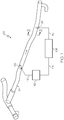
- a gas flow control valve 102 positioned to control a rate of gas flow through a duct 104.
- the gas flow control valve 102 may be a butterfly valve.
- a gas mass flow sensor 106 may be positioned downstream from the valve 102.
- the gas mass flow sensor 106 may be provided with a sensor control unit 108 which may receive temperature signals 110 from the gas mass flow sensor 106.
- the sensor control unit 108 may also provide electrical current to the gas mass flow sensor 106.
- a valve control unit 112 may receive sensing signals 114 from the sensor control unit 108 and provide corresponding valve positioning signals 116 to the valve 102.
- the gas mass flow sensor 104 may include an ambient temperature sensor 120 and a flow sensing device 122.
- the ambient temperature sensor 120 may be partially surrounded by a housing 124.
- the flow sensing device 122 may be partially surrounded by a housing 126.
- the flow sensing device 122 may include a thermally-conductive outer shell 128, a temperature-sensitive resistive element 130 and an electrical heater 132, both of which may be embedded in a heat-conducting material within the outer shell 128.
- the ambient temperature sensor 120 may be a temperature-sensitive resistive element.
- the gas mass flow sensor 104 may be configured so that the heater 132, during operation, maintains a desired temperature within the resistive element 130.
- the desired temperature may be established as a temperature that is a desired level above the ambient temperature as determined by the ambient temperature sensor 120.
- the desired temperature for the resistive element 130 may be selected as about 40° C greater than the ambient temperature.
- Gas flowing past the flow sensing device 122 may result in heat transfer from the resistive element 130, through the outer shell 128 and into the flowing gas.
- the heater 132 may supply heat to the resistive element 130 to offset the heat transfer and thus maintain the desired temperature within the resistive element 130.
- An amount of current needed to produce the requisite heating may be indicative of the rate of gas mass flow past the flow sensing device 122. For example, rapid cooling of the resistive element 130 may occur when gas flow rate is high. In that case, current supplied to the heater 132 may be correspondingly high. Conversely, when flow rate is low, current to the heater 132 may be correspondingly low.
- the control units 108 and 112 of Figure 1 may operate collectively to control angular positioning of the valve 102 and thereby regulate gas mass flow through the duct 104.
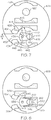
- the housing 126 may be provided with flow guidance elements 134.
- the flow guidance elements 134 may be formed integrally with the housing 126 or, alternatively, the elements 134 may be formed separately and then attached to the housing 126.
- the flow guidance elements 134 may be spaced apart from one another to form a flow path 150 with a width W, which width W may be about the same as a width of a leading surface 136 of the shell 128.
- the flow guidance elements 134 may have curved leading surfaces 138
- the leading surfaces 138 may be shaped as arc segments or as segments of an ellipse. In general shape of the leading surface may enable flow-vector stability, flow concentration, and enough mass flow to achieve a desired sensor sensitivity.
- gas flow entering the housing 126 may be guided so that it is concentrated onto the leading surface 136 of the shell 128.
- the leading surface 136 may be oriented substantially orthogonal to a direction of the gas flow.
- the flow may be driven outwardly toward inner surfaces 146 of the housing 126.
- the flow may be considered to be "lifted away" from an inboard surface 140 and an outboard surface 142 of the shell 128.
- heat may transfer from the resistive elements 130 to the flow, principally through the leading surface 136. Heat transfer through the inboard and outboard surfaces 140 and 142 may be negligible.
- the flow guidance elements 134 may be considered to be heat-transfer control elements positioned to focus heat transfer from the resistive element 130 through the leading surface 136 of the shell 128 so that a rate of heat transfer, at areas other than the leading surface 136, may be independent from the variations in flow configuration.
- incoming gas flow might not be lifted away from the inboard and the outboard surfaces 140 and 142 of the shell 128 and may instead envelop the surfaces 140 and 142.
- Such envelopment might be asymmetrical or otherwise non-uniform because the gas flow may experience any one of numerous possible variations of flow patterns that may have been introduced when the gas passed through the valve 102 of Figure 1 . Under such circumstances, heat transfer from the resistive element 130 to the gas flow might be non-uniform.
- the heat transfer might vary as a function of angular positioning of the valve 102 because, for example, gas flow may swirl in a clockwise direction (when viewed in the direction of lines 2-2 of Figure 1 ) at large valve opening angles, while at small valve opening angles, gas flow may swirl in a counterclockwise direction (when viewed in the direction of lines 2-2 of Figure 1 ).
- an exemplary embodiment of a gas mass flow sensor 206 may include a housing 224, a housing 226, ambient temperature sensor 220 and a flow sensing device 222.
- the gas mass flow sensor 206 may differ from the sensor 106 of Figures 3 and 4 in that there may be no flow guidance elements attached to the housing 226. Additionally the sensor 206 may differ from the sensor 106 in that an outer shell 228 may be provided with thermal insulators 244 along its inboard surface 240 and its outboard surface 242. The inboard and outboard surfaces 240 and 242 may be considered to be non-leading surfaces of the shell 228.
- the thermal insulators 244 may provide the beneficial effect of precluding heat transfer from the resistive element 230 to the gas flow through the inboard and outboard surfaces 240 and 242 of the shell 228.
- the thermal insulators 244 may be considered to be heat-transfer control elements positioned to focus heat transfer from the resistive element 230 through a leading surface 236 of the shell 228, which leading surface 236 may be oriented substantially orthogonal to a direction of gas flow. Consequently, a rate of heat transfer may be independent from the variations in flow configuration.
- the sensor 306 may differ from the sensor 206 of Figure 5 in that the sensor 306 is provided with flow guidance elements 336.
- the sensor 306 may differ from the sensor 106 of Figures 3 and 4 in that an outer shell 328 may be provided with thermal insulators 344 along its inboard surface 340 and its outboard surface 342.
- the gas mass flow sensor may include a housing 324, a housing 326, ambient temperature sensor 320, a flow sensing device 322 and flow guidance elements 334.
- the thermal insulators 344 in combination with the flow guidance elements 334, may provide the beneficial effect of precluding heat transfer from the resistive element 330 to the gas flow through the inboard and outboard surfaces 340 and 342 of the shell 328.
- the thermal insulators 344 and the flow guidance elements may be considered to be heat-transfer control elements positioned to focus heat transfer from the resistive element 330 through a leading surface 336 of the shell 328, which leading surface 336 may be oriented substantially orthogonal to a direction of gas flow. Consequently a rate of heat transfer may be independent from the variations in flow configuration.
- the gas mass flow sensor 406 may include a housing 424, a housing 426, ambient temperature sensor 420, a flow sensing device 422, flow guidance elements 434 and a shell 428.
- a flow opening or flow path 450 between the flow guidance elements 434 may have a width W2 that is about 50% of a length of the leading surface 436 of the shell 428.
- the leading surface 436 may be oriented substantially orthogonal to a direction of gas flow.
- Trailing surfaces 448 of the flow guidance elements 434 may be shaped as first arc segments.
- An inner surface 446 of the housing 426 may shaped as a second arc segment that is a continuation of the trailing surface 448 of an adjacent one of the flow guidance elements 434.
- a leading surface 436 of the shell 428 may be shaped as a third arc segment with a radius R1.
- the first and second arc segments may have a common radius R2 and may be concentric with the third arc segments.
- Gas flow entering the housing 426 may be initially directed to the leading surface 436 of the shell 428. The gas flow may then accelerate so that it tends to follow the trailing surfaces 448 of the flow guidance elements 434 and the inner surface 446 of the housing 426. Consequently, the gas flow may effectively "lift away" from the inboard and outboard surfaces 440 and 442 of the shell 428. Beneficial focusing of heat transfer through the leading surface 436 of the shell 428 may result.
- an exemplary embodiment of a gas mass flow sensor 506 may have a configuration similar to the gas mass flow sensor 406 of Figure 7 .
- the sensor 506 may differ from the sensor 406 in that a thermal insulator 550 may surround a trailing surface 552 and portions of an inboard surface 540 and outboard surface 542 of a shell 528.
- gas flow entering a housing 526 may be initially directed to a leading surface 536 of the shell 528. The gas flow may then accelerate so that it tends to follow trailing surfaces 548 of the flow guidance elements 534 and an inner surface 546 of a truncated housing 526.
- the gas flow may effectively "lift away" from inboard and outboard surfaces 540 and 542 of the shell 528.
- Beneficial focusing of heat transfer through the leading surface 536 of the shell may result. Further beneficial focusing of heat transfer may be provided by presence of the thermal insulator 550.
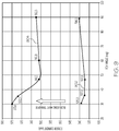
- Figure 9 illustrates some comparative data that demonstrates the efficacy of employing the flow guidance elements 134 on the gas mass flow sensor 106 of Figures 3 and 4 .
- a graph curve 902 illustrates an amount of current applied to the heater 132 in order to maintain a desired temperature in the resistive element 130 while maintain a constant flow rate of 60 pounds per minute (ppm). The current varies slightly as a function of angle of opening of the valve 102 of Figure 1 .
- Graph curve 904 illustrates a condition in which the flow guidance elements are removed from the sensor 106. The curve 904 shows an amount of current applied to the heater 132 in order to maintain a desired temperature in the resistive element 130 while maintaining a constant flow rate of 60 ppm.
- the current of curve 904 varies substantially as a function of angle of opening of the valve 102 of Figure 1 .
- Current variation may be particularly acute at valve opening angles less than about 50 degrees.
- the current variation of curve 902 may be about six times smaller than the current variation of curve 904 at a valve openings of 30 degrees.
Landscapes
- Engineering & Computer Science (AREA)
- General Engineering & Computer Science (AREA)
- Physics & Mathematics (AREA)
- General Physics & Mathematics (AREA)
- Fluid Mechanics (AREA)
- Mechanical Engineering (AREA)
- Automation & Control Theory (AREA)
- Measuring Volume Flow (AREA)
- Valve Housings (AREA)
Applications Claiming Priority (2)
| Application Number | Priority Date | Filing Date | Title |
|---|---|---|---|
| US14/611,448 US9500505B2 (en) | 2015-02-02 | 2015-02-02 | System for gas distribution and mass flow measurement |
| EP16153442.5A EP3051193B1 (de) | 2015-02-02 | 2016-01-29 | Gasverteilungssystem und massenstrommessung |
Related Parent Applications (1)
| Application Number | Title | Priority Date | Filing Date |
|---|---|---|---|
| EP16153442.5A Division EP3051193B1 (de) | 2015-02-02 | 2016-01-29 | Gasverteilungssystem und massenstrommessung |
Publications (2)
| Publication Number | Publication Date |
|---|---|
| EP3421948A1 true EP3421948A1 (de) | 2019-01-02 |
| EP3421948B1 EP3421948B1 (de) | 2021-01-27 |
Family
ID=55273156
Family Applications (2)
| Application Number | Title | Priority Date | Filing Date |
|---|---|---|---|
| EP16153442.5A Active EP3051193B1 (de) | 2015-02-02 | 2016-01-29 | Gasverteilungssystem und massenstrommessung |
| EP18182670.2A Active EP3421948B1 (de) | 2015-02-02 | 2016-01-29 | Gasverteilungssystem und massenstrommessung |
Family Applications Before (1)
| Application Number | Title | Priority Date | Filing Date |
|---|---|---|---|
| EP16153442.5A Active EP3051193B1 (de) | 2015-02-02 | 2016-01-29 | Gasverteilungssystem und massenstrommessung |
Country Status (2)
| Country | Link |
|---|---|
| US (1) | US9500505B2 (de) |
| EP (2) | EP3051193B1 (de) |
Families Citing this family (1)
| Publication number | Priority date | Publication date | Assignee | Title |
|---|---|---|---|---|
| DE102020109693B3 (de) * | 2020-04-07 | 2021-04-01 | Endress+Hauser Flowtec Ag | Thermisches Durchflussmessgerät |
Citations (5)
| Publication number | Priority date | Publication date | Assignee | Title |
|---|---|---|---|---|
| US20050262937A1 (en) * | 2004-05-25 | 2005-12-01 | Emmert Charles G Jr | Air flow measurement system having reduced sensitivity to flow field changes |
| US20110048564A1 (en) * | 2009-08-25 | 2011-03-03 | Fluid Components International Llc | Fluid flow conditioner |
| WO2012012769A2 (en) * | 2010-07-23 | 2012-01-26 | Fluid Components International Llc | Shield for heat transfer restriction for high flow rate use in a thermal flow rate sensor |
| EP1264160B1 (de) * | 2000-03-13 | 2012-04-18 | Honeywell International Inc. | Verfahren und vorrichtung zur messung und regelung einer flüssigkeitsströmung |
| WO2014075905A1 (de) * | 2012-11-16 | 2014-05-22 | Endress+Hauser Flowtec Ag | Sensor und durchflussmessgerät |
Family Cites Families (7)
| Publication number | Priority date | Publication date | Assignee | Title |
|---|---|---|---|---|
| US3146751A (en) | 1963-01-22 | 1964-09-01 | Schertel Hanns Von | Control device for stabilization of hydrofoils attached to water-craft |
| US5893146A (en) | 1995-08-31 | 1999-04-06 | Advanced Micro Design, Inc. | Cache structure having a reduced tag comparison to enable data transfer from said cache |
| KR20020028142A (ko) | 2000-10-07 | 2002-04-16 | 김봉구 | 쐐기모양을 갖는 평균 피토 튜브 유량센서 |
| US6487904B1 (en) * | 2000-11-09 | 2002-12-03 | Rosemont Aerospace Inc. | Method and sensor for mass flow measurement using probe heat conduction |
| US6910387B2 (en) | 2002-09-04 | 2005-06-28 | Endress + Hausser Flowtec Ag | Vortex flow sensor for measuring fluid flow through a flow tube |
| JP4836988B2 (ja) * | 2008-04-30 | 2011-12-14 | 日立オートモティブシステムズ株式会社 | 熱式流量計 |
| US9182261B1 (en) * | 2014-12-24 | 2015-11-10 | Finetek Co., Ltd. | Thermal mass flow meter |
-
2015
- 2015-02-02 US US14/611,448 patent/US9500505B2/en active Active
-
2016
- 2016-01-29 EP EP16153442.5A patent/EP3051193B1/de active Active
- 2016-01-29 EP EP18182670.2A patent/EP3421948B1/de active Active
Patent Citations (5)
| Publication number | Priority date | Publication date | Assignee | Title |
|---|---|---|---|---|
| EP1264160B1 (de) * | 2000-03-13 | 2012-04-18 | Honeywell International Inc. | Verfahren und vorrichtung zur messung und regelung einer flüssigkeitsströmung |
| US20050262937A1 (en) * | 2004-05-25 | 2005-12-01 | Emmert Charles G Jr | Air flow measurement system having reduced sensitivity to flow field changes |
| US20110048564A1 (en) * | 2009-08-25 | 2011-03-03 | Fluid Components International Llc | Fluid flow conditioner |
| WO2012012769A2 (en) * | 2010-07-23 | 2012-01-26 | Fluid Components International Llc | Shield for heat transfer restriction for high flow rate use in a thermal flow rate sensor |
| WO2014075905A1 (de) * | 2012-11-16 | 2014-05-22 | Endress+Hauser Flowtec Ag | Sensor und durchflussmessgerät |
Also Published As
| Publication number | Publication date |
|---|---|
| EP3051193A3 (de) | 2016-11-30 |
| EP3051193B1 (de) | 2018-07-11 |
| US9500505B2 (en) | 2016-11-22 |
| EP3051193A2 (de) | 2016-08-03 |
| US20160223375A1 (en) | 2016-08-04 |
| EP3421948B1 (de) | 2021-01-27 |
Similar Documents
| Publication | Publication Date | Title |
|---|---|---|
| CN111279058B (zh) | 用于确定可电加热的催化转化器的加热元件的加热温度的设备和方法以及机动车辆 | |
| JP5541576B2 (ja) | 風向風速計および風向風速装置 | |
| US10401206B2 (en) | Thermal, flow measuring device | |
| KR100324840B1 (ko) | 감열식유량센서 | |
| US6079264A (en) | Thermal flow sensor supporting element having a gradually increased portion between its distal ends | |
| WO2006027974A1 (ja) | 流量センサ | |
| US20150300856A1 (en) | Thermal, Flow Measuring Device | |
| US9810586B2 (en) | Temperature sensor and thermal, flow measuring device | |
| JPH0579875A (ja) | 熱式流量計 | |
| US11280650B2 (en) | Thermal flowmeter and method for operating a thermal flowmeter | |
| US11047775B2 (en) | Paraffin distribution device for embedder and embedder with the same | |
| JP6916667B2 (ja) | プローブデバイス、及び、排ガス分析装置 | |
| EP3051193B1 (de) | Gasverteilungssystem und massenstrommessung | |
| US12152942B2 (en) | Noninvasive thermometer | |
| US9739652B2 (en) | Sensor and flow measuring device | |
| US10222248B2 (en) | Platinum temperature sensor element | |
| JP2000019195A (ja) | 風向風速計測装置 | |
| US11761806B2 (en) | Thermal flowmeter | |
| EP1363109B1 (de) | Strömungsmesser mit widerstandsheizelement | |
| JPH1114466A (ja) | ガス温度計 | |
| RU99105505A (ru) | Способ измерения расхода газа и устройство для его осуществления | |
| US20050034982A1 (en) | Sensor holder | |
| JPS6361918A (ja) | 挿入形熱式流量計 | |
| JPH0531539Y2 (de) | ||
| JP2002333357A (ja) | 液体用熱式質量流量計 |
Legal Events
| Date | Code | Title | Description |
|---|---|---|---|
| PUAI | Public reference made under article 153(3) epc to a published international application that has entered the european phase |
Free format text: ORIGINAL CODE: 0009012 |
|
| STAA | Information on the status of an ep patent application or granted ep patent |
Free format text: STATUS: REQUEST FOR EXAMINATION WAS MADE |
|
| 17P | Request for examination filed |
Effective date: 20180710 |
|
| AC | Divisional application: reference to earlier application |
Ref document number: 3051193 Country of ref document: EP Kind code of ref document: P |
|
| AK | Designated contracting states |
Kind code of ref document: A1 Designated state(s): AL AT BE BG CH CY CZ DE DK EE ES FI FR GB GR HR HU IE IS IT LI LT LU LV MC MK MT NL NO PL PT RO RS SE SI SK SM TR |
|
| STAA | Information on the status of an ep patent application or granted ep patent |
Free format text: STATUS: EXAMINATION IS IN PROGRESS |
|
| 17Q | First examination report despatched |
Effective date: 20200213 |
|
| RIC1 | Information provided on ipc code assigned before grant |
Ipc: G05D 7/06 20060101ALI20200730BHEP Ipc: G01F 15/00 20060101ALI20200730BHEP Ipc: F16K 1/22 20060101ALI20200730BHEP Ipc: G01F 1/684 20060101AFI20200730BHEP Ipc: F16K 37/00 20060101ALI20200730BHEP |
|
| GRAP | Despatch of communication of intention to grant a patent |
Free format text: ORIGINAL CODE: EPIDOSNIGR1 |
|
| STAA | Information on the status of an ep patent application or granted ep patent |
Free format text: STATUS: GRANT OF PATENT IS INTENDED |
|
| INTG | Intention to grant announced |
Effective date: 20200930 |
|
| GRAS | Grant fee paid |
Free format text: ORIGINAL CODE: EPIDOSNIGR3 |
|
| GRAA | (expected) grant |
Free format text: ORIGINAL CODE: 0009210 |
|
| STAA | Information on the status of an ep patent application or granted ep patent |
Free format text: STATUS: THE PATENT HAS BEEN GRANTED |
|
| AC | Divisional application: reference to earlier application |
Ref document number: 3051193 Country of ref document: EP Kind code of ref document: P |
|
| AK | Designated contracting states |
Kind code of ref document: B1 Designated state(s): AL AT BE BG CH CY CZ DE DK EE ES FI FR GB GR HR HU IE IS IT LI LT LU LV MC MK MT NL NO PL PT RO RS SE SI SK SM TR |
|
| REG | Reference to a national code |
Ref country code: GB Ref legal event code: FG4D |
|
| REG | Reference to a national code |
Ref country code: CH Ref legal event code: EP |
|
| REG | Reference to a national code |
Ref country code: AT Ref legal event code: REF Ref document number: 1358778 Country of ref document: AT Kind code of ref document: T Effective date: 20210215 |
|
| REG | Reference to a national code |
Ref country code: IE Ref legal event code: FG4D |
|
| REG | Reference to a national code |
Ref country code: DE Ref legal event code: R096 Ref document number: 602016052296 Country of ref document: DE |
|
| REG | Reference to a national code |
Ref country code: NL Ref legal event code: MP Effective date: 20210127 |
|
| REG | Reference to a national code |
Ref country code: LT Ref legal event code: MG9D |
|
| REG | Reference to a national code |
Ref country code: AT Ref legal event code: MK05 Ref document number: 1358778 Country of ref document: AT Kind code of ref document: T Effective date: 20210127 |
|
| PG25 | Lapsed in a contracting state [announced via postgrant information from national office to epo] |
Ref country code: BG Free format text: LAPSE BECAUSE OF FAILURE TO SUBMIT A TRANSLATION OF THE DESCRIPTION OR TO PAY THE FEE WITHIN THE PRESCRIBED TIME-LIMIT Effective date: 20210427 Ref country code: GR Free format text: LAPSE BECAUSE OF FAILURE TO SUBMIT A TRANSLATION OF THE DESCRIPTION OR TO PAY THE FEE WITHIN THE PRESCRIBED TIME-LIMIT Effective date: 20210428 Ref country code: FI Free format text: LAPSE BECAUSE OF FAILURE TO SUBMIT A TRANSLATION OF THE DESCRIPTION OR TO PAY THE FEE WITHIN THE PRESCRIBED TIME-LIMIT Effective date: 20210127 Ref country code: HR Free format text: LAPSE BECAUSE OF FAILURE TO SUBMIT A TRANSLATION OF THE DESCRIPTION OR TO PAY THE FEE WITHIN THE PRESCRIBED TIME-LIMIT Effective date: 20210127 Ref country code: NO Free format text: LAPSE BECAUSE OF FAILURE TO SUBMIT A TRANSLATION OF THE DESCRIPTION OR TO PAY THE FEE WITHIN THE PRESCRIBED TIME-LIMIT Effective date: 20210427 Ref country code: PT Free format text: LAPSE BECAUSE OF FAILURE TO SUBMIT A TRANSLATION OF THE DESCRIPTION OR TO PAY THE FEE WITHIN THE PRESCRIBED TIME-LIMIT Effective date: 20210527 Ref country code: LT Free format text: LAPSE BECAUSE OF FAILURE TO SUBMIT A TRANSLATION OF THE DESCRIPTION OR TO PAY THE FEE WITHIN THE PRESCRIBED TIME-LIMIT Effective date: 20210127 |
|
| PG25 | Lapsed in a contracting state [announced via postgrant information from national office to epo] |
Ref country code: SE Free format text: LAPSE BECAUSE OF FAILURE TO SUBMIT A TRANSLATION OF THE DESCRIPTION OR TO PAY THE FEE WITHIN THE PRESCRIBED TIME-LIMIT Effective date: 20210127 Ref country code: AT Free format text: LAPSE BECAUSE OF FAILURE TO SUBMIT A TRANSLATION OF THE DESCRIPTION OR TO PAY THE FEE WITHIN THE PRESCRIBED TIME-LIMIT Effective date: 20210127 Ref country code: PL Free format text: LAPSE BECAUSE OF FAILURE TO SUBMIT A TRANSLATION OF THE DESCRIPTION OR TO PAY THE FEE WITHIN THE PRESCRIBED TIME-LIMIT Effective date: 20210127 Ref country code: LV Free format text: LAPSE BECAUSE OF FAILURE TO SUBMIT A TRANSLATION OF THE DESCRIPTION OR TO PAY THE FEE WITHIN THE PRESCRIBED TIME-LIMIT Effective date: 20210127 Ref country code: RS Free format text: LAPSE BECAUSE OF FAILURE TO SUBMIT A TRANSLATION OF THE DESCRIPTION OR TO PAY THE FEE WITHIN THE PRESCRIBED TIME-LIMIT Effective date: 20210127 |
|
| REG | Reference to a national code |
Ref country code: CH Ref legal event code: PL |
|
| PG25 | Lapsed in a contracting state [announced via postgrant information from national office to epo] |
Ref country code: LU Free format text: LAPSE BECAUSE OF NON-PAYMENT OF DUE FEES Effective date: 20210129 Ref country code: IS Free format text: LAPSE BECAUSE OF FAILURE TO SUBMIT A TRANSLATION OF THE DESCRIPTION OR TO PAY THE FEE WITHIN THE PRESCRIBED TIME-LIMIT Effective date: 20210527 |
|
| REG | Reference to a national code |
Ref country code: BE Ref legal event code: MM Effective date: 20210131 |
|
| REG | Reference to a national code |
Ref country code: DE Ref legal event code: R097 Ref document number: 602016052296 Country of ref document: DE |
|
| PG25 | Lapsed in a contracting state [announced via postgrant information from national office to epo] |
Ref country code: MC Free format text: LAPSE BECAUSE OF FAILURE TO SUBMIT A TRANSLATION OF THE DESCRIPTION OR TO PAY THE FEE WITHIN THE PRESCRIBED TIME-LIMIT Effective date: 20210127 Ref country code: CZ Free format text: LAPSE BECAUSE OF FAILURE TO SUBMIT A TRANSLATION OF THE DESCRIPTION OR TO PAY THE FEE WITHIN THE PRESCRIBED TIME-LIMIT Effective date: 20210127 Ref country code: EE Free format text: LAPSE BECAUSE OF FAILURE TO SUBMIT A TRANSLATION OF THE DESCRIPTION OR TO PAY THE FEE WITHIN THE PRESCRIBED TIME-LIMIT Effective date: 20210127 Ref country code: SM Free format text: LAPSE BECAUSE OF FAILURE TO SUBMIT A TRANSLATION OF THE DESCRIPTION OR TO PAY THE FEE WITHIN THE PRESCRIBED TIME-LIMIT Effective date: 20210127 |
|
| PG25 | Lapsed in a contracting state [announced via postgrant information from national office to epo] |
Ref country code: DK Free format text: LAPSE BECAUSE OF FAILURE TO SUBMIT A TRANSLATION OF THE DESCRIPTION OR TO PAY THE FEE WITHIN THE PRESCRIBED TIME-LIMIT Effective date: 20210127 Ref country code: CH Free format text: LAPSE BECAUSE OF NON-PAYMENT OF DUE FEES Effective date: 20210131 Ref country code: SK Free format text: LAPSE BECAUSE OF FAILURE TO SUBMIT A TRANSLATION OF THE DESCRIPTION OR TO PAY THE FEE WITHIN THE PRESCRIBED TIME-LIMIT Effective date: 20210127 Ref country code: RO Free format text: LAPSE BECAUSE OF FAILURE TO SUBMIT A TRANSLATION OF THE DESCRIPTION OR TO PAY THE FEE WITHIN THE PRESCRIBED TIME-LIMIT Effective date: 20210127 Ref country code: LI Free format text: LAPSE BECAUSE OF NON-PAYMENT OF DUE FEES Effective date: 20210131 |
|
| PLBE | No opposition filed within time limit |
Free format text: ORIGINAL CODE: 0009261 |
|
| STAA | Information on the status of an ep patent application or granted ep patent |
Free format text: STATUS: NO OPPOSITION FILED WITHIN TIME LIMIT |
|
| 26N | No opposition filed |
Effective date: 20211028 |
|
| PG25 | Lapsed in a contracting state [announced via postgrant information from national office to epo] |
Ref country code: FR Free format text: LAPSE BECAUSE OF NON-PAYMENT OF DUE FEES Effective date: 20210327 Ref country code: ES Free format text: LAPSE BECAUSE OF FAILURE TO SUBMIT A TRANSLATION OF THE DESCRIPTION OR TO PAY THE FEE WITHIN THE PRESCRIBED TIME-LIMIT Effective date: 20210127 Ref country code: IE Free format text: LAPSE BECAUSE OF NON-PAYMENT OF DUE FEES Effective date: 20210129 Ref country code: AL Free format text: LAPSE BECAUSE OF FAILURE TO SUBMIT A TRANSLATION OF THE DESCRIPTION OR TO PAY THE FEE WITHIN THE PRESCRIBED TIME-LIMIT Effective date: 20210127 |
|
| PG25 | Lapsed in a contracting state [announced via postgrant information from national office to epo] |
Ref country code: SI Free format text: LAPSE BECAUSE OF FAILURE TO SUBMIT A TRANSLATION OF THE DESCRIPTION OR TO PAY THE FEE WITHIN THE PRESCRIBED TIME-LIMIT Effective date: 20210127 |
|
| PG25 | Lapsed in a contracting state [announced via postgrant information from national office to epo] |
Ref country code: IT Free format text: LAPSE BECAUSE OF FAILURE TO SUBMIT A TRANSLATION OF THE DESCRIPTION OR TO PAY THE FEE WITHIN THE PRESCRIBED TIME-LIMIT Effective date: 20210127 |
|
| PG25 | Lapsed in a contracting state [announced via postgrant information from national office to epo] |
Ref country code: IS Free format text: LAPSE BECAUSE OF FAILURE TO SUBMIT A TRANSLATION OF THE DESCRIPTION OR TO PAY THE FEE WITHIN THE PRESCRIBED TIME-LIMIT Effective date: 20210527 |
|
| PG25 | Lapsed in a contracting state [announced via postgrant information from national office to epo] |
Ref country code: BE Free format text: LAPSE BECAUSE OF NON-PAYMENT OF DUE FEES Effective date: 20210131 |
|
| PG25 | Lapsed in a contracting state [announced via postgrant information from national office to epo] |
Ref country code: NL Free format text: LAPSE BECAUSE OF NON-PAYMENT OF DUE FEES Effective date: 20210127 Ref country code: CY Free format text: LAPSE BECAUSE OF FAILURE TO SUBMIT A TRANSLATION OF THE DESCRIPTION OR TO PAY THE FEE WITHIN THE PRESCRIBED TIME-LIMIT Effective date: 20210127 |
|
| P01 | Opt-out of the competence of the unified patent court (upc) registered |
Effective date: 20230525 |
|
| PG25 | Lapsed in a contracting state [announced via postgrant information from national office to epo] |
Ref country code: HU Free format text: LAPSE BECAUSE OF FAILURE TO SUBMIT A TRANSLATION OF THE DESCRIPTION OR TO PAY THE FEE WITHIN THE PRESCRIBED TIME-LIMIT; INVALID AB INITIO Effective date: 20160129 |
|
| PG25 | Lapsed in a contracting state [announced via postgrant information from national office to epo] |
Ref country code: MK Free format text: LAPSE BECAUSE OF FAILURE TO SUBMIT A TRANSLATION OF THE DESCRIPTION OR TO PAY THE FEE WITHIN THE PRESCRIBED TIME-LIMIT Effective date: 20210127 |
|
| PG25 | Lapsed in a contracting state [announced via postgrant information from national office to epo] |
Ref country code: MT Free format text: LAPSE BECAUSE OF FAILURE TO SUBMIT A TRANSLATION OF THE DESCRIPTION OR TO PAY THE FEE WITHIN THE PRESCRIBED TIME-LIMIT Effective date: 20210127 |
|
| PG25 | Lapsed in a contracting state [announced via postgrant information from national office to epo] |
Ref country code: TR Free format text: LAPSE BECAUSE OF FAILURE TO SUBMIT A TRANSLATION OF THE DESCRIPTION OR TO PAY THE FEE WITHIN THE PRESCRIBED TIME-LIMIT Effective date: 20210127 |
|
| PGFP | Annual fee paid to national office [announced via postgrant information from national office to epo] |
Ref country code: GB Payment date: 20260126 Year of fee payment: 11 |
|
| PGFP | Annual fee paid to national office [announced via postgrant information from national office to epo] |
Ref country code: DE Payment date: 20260127 Year of fee payment: 11 |