EP3422121B1 - Systèmes d'arrêt d'urgence sans fil et procédés correspondants permettant de faire fonctionner un système d'arrêt d'urgence sans fil pour une machine d'interface de sécurité - Google Patents
Systèmes d'arrêt d'urgence sans fil et procédés correspondants permettant de faire fonctionner un système d'arrêt d'urgence sans fil pour une machine d'interface de sécurité Download PDFInfo
- Publication number
- EP3422121B1 EP3422121B1 EP18172056.6A EP18172056A EP3422121B1 EP 3422121 B1 EP3422121 B1 EP 3422121B1 EP 18172056 A EP18172056 A EP 18172056A EP 3422121 B1 EP3422121 B1 EP 3422121B1
- Authority
- EP
- European Patent Office
- Prior art keywords
- machine
- safety device
- personal safety
- emergency stop
- personal
- Prior art date
- Legal status (The legal status is an assumption and is not a legal conclusion. Google has not performed a legal analysis and makes no representation as to the accuracy of the status listed.)
- Active
Links
Images

Classifications
-
- G—PHYSICS
- G05—CONTROLLING; REGULATING
- G05B—CONTROL OR REGULATING SYSTEMS IN GENERAL; FUNCTIONAL ELEMENTS OF SUCH SYSTEMS; MONITORING OR TESTING ARRANGEMENTS FOR SUCH SYSTEMS OR ELEMENTS
- G05B19/00—Program-control systems
- G05B19/02—Program-control systems electric
- G05B19/04—Program control other than numerical control, i.e. in sequence controllers or logic controllers
- G05B19/048—Monitoring; Safety
-
- G—PHYSICS
- G05—CONTROLLING; REGULATING
- G05B—CONTROL OR REGULATING SYSTEMS IN GENERAL; FUNCTIONAL ELEMENTS OF SUCH SYSTEMS; MONITORING OR TESTING ARRANGEMENTS FOR SUCH SYSTEMS OR ELEMENTS
- G05B9/00—Safety arrangements
- G05B9/02—Safety arrangements electric
-
- G—PHYSICS
- G05—CONTROLLING; REGULATING
- G05B—CONTROL OR REGULATING SYSTEMS IN GENERAL; FUNCTIONAL ELEMENTS OF SUCH SYSTEMS; MONITORING OR TESTING ARRANGEMENTS FOR SUCH SYSTEMS OR ELEMENTS
- G05B19/00—Program-control systems
- G05B19/02—Program-control systems electric
- G05B19/04—Program control other than numerical control, i.e. in sequence controllers or logic controllers
- G05B19/042—Program control other than numerical control, i.e. in sequence controllers or logic controllers using digital processors
- G05B19/0423—Input/output
- G05B19/0425—Safety, monitoring
-
- G—PHYSICS
- G05—CONTROLLING; REGULATING
- G05B—CONTROL OR REGULATING SYSTEMS IN GENERAL; FUNCTIONAL ELEMENTS OF SUCH SYSTEMS; MONITORING OR TESTING ARRANGEMENTS FOR SUCH SYSTEMS OR ELEMENTS
- G05B19/00—Program-control systems
- G05B19/02—Program-control systems electric
- G05B19/04—Program control other than numerical control, i.e. in sequence controllers or logic controllers
- G05B19/05—Programmable logic controllers, e.g. simulating logic interconnections of signals according to ladder diagrams or function charts
- G05B19/058—Safety, monitoring
-
- G—PHYSICS
- G05—CONTROLLING; REGULATING
- G05B—CONTROL OR REGULATING SYSTEMS IN GENERAL; FUNCTIONAL ELEMENTS OF SUCH SYSTEMS; MONITORING OR TESTING ARRANGEMENTS FOR SUCH SYSTEMS OR ELEMENTS
- G05B9/00—Safety arrangements
- G05B9/02—Safety arrangements electric
- G05B9/03—Safety arrangements electric with multiple-channel loop, i.e. redundant control systems
-
- G—PHYSICS
- G08—SIGNALLING
- G08C—TRANSMISSION SYSTEMS FOR MEASURED VALUES, CONTROL OR SIMILAR SIGNALS
- G08C17/00—Arrangements for transmitting signals characterised by the use of a wireless electrical link
- G08C17/02—Arrangements for transmitting signals characterised by the use of a wireless electrical link using a radio link
-
- G—PHYSICS
- G05—CONTROLLING; REGULATING
- G05B—CONTROL OR REGULATING SYSTEMS IN GENERAL; FUNCTIONAL ELEMENTS OF SUCH SYSTEMS; MONITORING OR TESTING ARRANGEMENTS FOR SUCH SYSTEMS OR ELEMENTS
- G05B2219/00—Program-control systems
- G05B2219/10—Plc systems
- G05B2219/14—Plc safety
- G05B2219/14116—Safe, emergency shutdown, esd of system
-
- G—PHYSICS
- G05—CONTROLLING; REGULATING
- G05B—CONTROL OR REGULATING SYSTEMS IN GENERAL; FUNCTIONAL ELEMENTS OF SUCH SYSTEMS; MONITORING OR TESTING ARRANGEMENTS FOR SUCH SYSTEMS OR ELEMENTS
- G05B2219/00—Program-control systems
- G05B2219/10—Plc systems
- G05B2219/15—Plc structure of the system
- G05B2219/15117—Radio link, wireless
-
- G—PHYSICS
- G05—CONTROLLING; REGULATING
- G05B—CONTROL OR REGULATING SYSTEMS IN GENERAL; FUNCTIONAL ELEMENTS OF SUCH SYSTEMS; MONITORING OR TESTING ARRANGEMENTS FOR SUCH SYSTEMS OR ELEMENTS
- G05B2219/00—Program-control systems
- G05B2219/20—Pc systems
- G05B2219/24—Pc safety
- G05B2219/24003—Emergency stop
-
- G—PHYSICS
- G05—CONTROLLING; REGULATING
- G05B—CONTROL OR REGULATING SYSTEMS IN GENERAL; FUNCTIONAL ELEMENTS OF SUCH SYSTEMS; MONITORING OR TESTING ARRANGEMENTS FOR SUCH SYSTEMS OR ELEMENTS
- G05B2219/00—Program-control systems
- G05B2219/20—Pc systems
- G05B2219/24—Pc safety
- G05B2219/24024—Safety, surveillance
Definitions
- the present disclosure generally relates to a wireless emergency stop system and corresponding method of operating a wireless emergency stop system including a machine safety device.
- Hardwired emergency stop stations are often used in connection for machine and equipment safety, to allow operators to safely bring a machine or process to a safe state. However, these hardwired stations can require time for an operator to move to the location of the hardwired stop switch in order to trigger the emergency stop process.
- the invention relates to a wireless emergency stop system according to claim 1.
- the invention further relates to a method of operating a wireless emergency stop system according to claim 8.
- the prior art includes the system and method for remote control of unmanned vehicles disclosed in US 2015/032293 , the emergency press button with wireless receiving function disclosed in CN 202205338 , the crane control system for controlling a plurality of cranes disclosed in US 2017/031339 , and the method of operating a mobile hand-operated device for outputting or enabling potentially dangerous control commands disclosed in US 2011/160910 .
- hardwired emergency stop stations are often used in connection for machine and equipment safety, to allow operators to safely bring a machine or process to a safe state.
- these hardwired stations can require time for an operator to move to the location of the hardwired stop switch in order to trigger the emergency stop process.
- a wireless emergency stop switch can bring emergency stop capability directly to the user, and enable the user to instantly activate the emergency stop switch even when a hardwired station is out of reach or in a hazard zone.
- wireless emergency stop systems including one or more personal safety devices (PSDs) each having an emergency stop (E-stop) switch.
- the systems also include one or more machine safety devices (MSDs) that are connected to ( e . g ., wired in, etc .) to a hardwired emergency stop circuit.
- PSDs personal safety devices
- MSDs machine safety devices
- multiple personal safety devices operate with a single machine safety device.
- the personal safety devices follow a linking protocol with the machine safety device that allows the personal safety devices to de-link ( e . g ., when no longer being used, etc .) without shutting down the machine connected to the machine safety device.
- a machine safety device is hardwired into a machine stop circuit (e . g ., a safety circuit capable of shutting down operation of the machine, etc .).
- the machine stop circuit includes a radio interface capable of wireless communication with multiple personal safety devices.
- the machine safety device implements a high level of safety by maintaining its safety relay(s) closed ( e . g ., so that a connected machine is allowed to operate normally, etc .) when no personal safety devices are connected to the machine safety device and no internal faults of the machine safety device are detected. If one or more personal safety devices are connected ( e . g ., linked, etc.) with the machine safety device, the machine safety device will maintain its safety relays closed when wireless (e . g ., radio frequency (RF), etc .) communication with all connected personal safety devices is good ( e . g ., has a sufficient threshold connection quality, etc .) and no connected personal safety devices have activated an emergency stop switch. In some cases, the machine safety device may only maintain its safety relays closed when the above conditions are true.
- RF radio frequency
- the machine safety device opens its safety relay(s) ( e . g ., to stop operation of the connected machine, etc .) when any of the following conditions occur: an internal fault of the machine safety device is detected, a connected personal safety device loses wireless communication with the machine safety device, a connected personal safety device activates its emergency stop switch, a fault of a connected personal safety device is detected, etc.
- a safety relay(s) e . g ., to stop operation of the connected machine, etc .
- each personal safety device follows a protocol for linking to and de-linking from the machine safety device without causing a stop of the machine connected to the machine safety device.
- This protocol includes one or more direct actions from the operator to link or de-link the personal safety device, which are distinctly different from a loss of wireless communication or activation of the emergency stop switch of the personal safety device.
- Examples of wireless emergency stop systems can provide a simpler method for connecting multiple wireless emergency stop devices with a single machine safety device, increase efficiency and lower cost as compared to using multiple machine safety devices, etc.
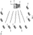
- FIG. 1 illustrates an exemplary embodiment of a wireless emergency stop system 100 having a machine safety device 102 (e . g ., machine control unit (MCU)) and a machine stop circuit 104.
- the machine safety device 102 is wired to the machine stop circuit 104 for stopping operation of a machine (not shown) when the machine stop circuit 104 is activated.
- MCU machine control unit
- the machine safety device 102 includes a wireless communication interface 106.
- the wireless communication interface 106 of the machine safety device 102 may include any suitable antenna configured for wireless communication (e . g ., radio frequency (RF) wireless communication, etc .) .
- RF radio frequency
- the system 100 also includes multiple personal safety devices 108 (e . g ., operator control units (OCUs), etc. ).
- Each personal safety device 108 includes a wireless communication interface for wireless communication with the machine safety device 102 ( e . g ., via the wireless communication interface 106 of the machine safety device 102, etc .).
- Each personal safety device 108 includes an emergency stop button 110.
- the emergency stop button 110 is configured to, when activated ( e . g ., by an operator carrying the personal safety device 108, etc .), transmit an emergency stop signal to the machine safety device 102 to trigger an emergency stop of the machine ( e . g ., via the machine stop circuit 104, etc .). Therefore, an operator carrying a personal safety device 108 may use the emergency stop button 110 to quickly trigger an emergency stop of a machine, without having to move to the location of the machine safety device 102. In some embodiments, activation of the emergency stop button 110 may trigger an emergency stop of the machine within less than about 500 milliseconds, etc.
- the machine safety device 102 is configured to maintain wireless connection with more than one of the personal safety devices 108 at the same time. This provides multiple operators with the ability to trigger an emergency stop of a machine via their corresponding personal safety devices 108. For example, the machine safety device 102 may maintain wireless communication with three personal safety devices 108 simultaneously, with five personal safety devices 108 simultaneously, with ten personal safety devices 108 simultaneously, etc.
- the machine safety device 102 includes several protocols for determining when to activate the machine stop circuit 104 to stop operation of the machine, and the each personal safety device 108 follows a linking and de-linking protocol to wirelessly connect to and disconnect from the machine safety device 102 without triggering an emergency stop.
- This allows multiple operators to connect a personal safety device 108 as desired ( e . g ., when working with the machine connected to the machine stop circuit 104, etc .), while also allowing the operators to disconnect the personal safety device 108 when they are finished working with machine, when the personal safety device 108 needs to charge, etc.
- the machine safety device 102 includes one or more safety relays.
- the machine safety device 102 may include one or more safety relays for activation in response to an emergency stop button activation, and one or more safety relays for activation in response to a loss of wireless communication.
- Each of the one or more safety relays may be connected to the machine stop circuit 104.
- the relays may include multiple switches ( e . g ., single contact switches, two-level enable switches, etc .).
- the relays may be redundant ( e . g ., redundant E-stop relays and communication loss relays, etc .).
- two safety relays may be wired in series with an external hard-wired E-stop circuit that allows a machine to run.
- the machine safety device 102 may open the relay(s) to stop operation of the machine when an emergency stop is triggered by one of the multiple personal safety devices 108.
- the machine safety device 102 may maintain the relay(s) in a closed state to allow operation of the machine while the emergency stop is not triggered.
- the machine safety device 102 may use any suitable protocol(s) for determining when to allow normal operation of the machine ( e . g ., by leaving relay(s) of the machine safety device 102 in a closed state, etc .).
- the machine safety device will maintain normal operation when no internal fault of the machine safety device 102 is detected.
- the machine safety device When one or more personal safety devices 108 are connected with the machine safety device 102, the machine safety device is configured to maintain normal operation of the machine when all of the connected personal safety devices 108 have wireless communication above a signal quality threshold (e . g ., a threshold indicative of sufficient RF signal strength, such as an RSSI threshold value, etc .), and none of the connected personal safety devices 108 have an activated emergency stop switch 110.
- a signal quality threshold e . g ., a threshold indicative of sufficient RF signal strength, such as an RSSI threshold value, etc .
- a specific number of personal safety devices 108 e . g ., one personal safety device 108, two personal safety devices 108, three personal safety devices 108, etc .
- the machine safety device 102 may stop operation of the machine ( e . g ., by opening a relay of the machine safety device 102, etc .) when any one of multiple events occurs: an internal fault of the machine safety device 102 is detected; one of the personal safety devices 108 currently connected with the machine safety device 102 loses wireless communication with the machine safety device 102; one of the personal safety devices 108 currently connected with the machine safety device 102 has an activated emergency stop switch 110; one or more of the multiple personal safety devices 108 currently connected with the machine safety device has a detected fault; etc.
- Any suitable RF protocol may be used for communication between the personal safety devices 108 and the machine safety device 102.
- a specific RF frequency band may be selected so that the personal safety devices 108 and the machine safety device 102 operate on the same channel.
- two RF channels may be used in a frequency diversity mode to increase immunity to RF interference.
- Each RF frequency band may include a defined number of available RF channels.
- Each of the personal safety devices 108 is configured to wirelessly connect to and disconnect from the machine safety device 102 according to a linking protocol that does not trigger an emergency stop of the machine.
- the linking protocol involves a personal safety device 108 receiving an action from an operator ( e . g ., activating a specific button, etc .) that is distinct from a loss of wireless communication with the machine safety device 102, and is distinct from activation of the emergency stop switch 110 of the personal safety device 108.
- the linking protocol allows the personal safety devices 108 to be connected to and disconnected with the machine safety device 102 as desired, without triggering an emergency stop of the machine each time a personal safety device 108 is de-linked from the machine safety device 102.
- a user may hold down a linking button of the personal safety device 108 for a period of time (e . g ., at least half a second, etc .) when in range of the machine safety device 102.
- the linking button is separate from the emergency stop button. If a link is established, the personal safety device 108 may indicate the successful connection via an indicator on the personal safety device 108.
- Each message may include an identifier that is unique to the machine in use, and may include a system address to inhibit the machine safety device from acting upon unassigned personal safety devices when an address combination does not match. For example, a system address may be matched with a sub-address of the PSD, a sub-address of the MSD, etc.
- a user may unlink the personal safety device 108 from the machine safety device 102 using the linking and unlinking protocol that is separate from triggering an emergency stop. For example, a user may press an unlinking button for a specified amount of time (e . g ., at least about three seconds, etc .) to unlink the personal safety device 108.
- the unlinking button may be the same as or separate from the linking button mentioned above, but should not be the same as the emergency stop button of the personal safety device 108.
- An indicator of the personal safety device 108 may indicate when the unlinking process is complete.
- a personal safety device 108 when a personal safety device 108 activates an emergency stop, other personal safety devices 108 connected with the machine safety device may be notified of the emergency stop event, and also may be notified of which personal safety device 108 triggered the emergency stop.
- Each personal safety device 108 may be configured as a machine access control where, e.g., the machine safety device 102 is configured to only allow the machine to run when a specified minimum number of personal safety devices 108 are online ( e . g ., connected with the machine safety device, etc .).
- the machine safety device 102 may require at least one personal safety device 102 to be connected, at least two personal safety devices 102 to be connected, etc ., before the machine safety device closes safety relay(s), before a safety bus issues a go condition command, etc. Therefore, if one or more users are attempting to control a machine, the machine safety device 102 can first check whether corresponding personal safety devices 108 are connected before allowing operation of the machine.
- Each personal safety device may include a secure protocol for identifying a user, such as a radio frequency identification (RFID) card, a biometric identifier, etc.
- RFID radio frequency identification
- the user may have pre-defined authorization right(s), which can be stored locally and/or remotely. If the user has appropriate authorization right(s), the personal safety device 108 may be allowed to connect to the machine safety device 102. When the correct number of personal safety devices 108 are connected to the machine safety device 102, the machine safety device 102 can close its relay(s) and allow the machine to operate.
- the machine safety device 102 and the personal safety devices 108 may comprise any suitable devices ( e . g ., computing devices, etc .) which may be configured to perform operations described herein using any suitable combination of software and/or hardware.
- the machine safety device 102 and the personal safety devices may include any suitable circuitry, logic gates, microprocessor(s), computer-executable instructions stored in memory, etc ., operable to cause the machine safety device 102 and the personal safety devices 108 to perform the actions described herein ( e . g ., triggering an emergency stop, etc .).
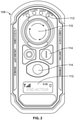
- FIG. 2 illustrates one of the personal safety devices 108 of the wireless emergency stop system 100 shown in FIG. 1 .
- the personal safety device 108 includes an emergency stop switch 110.
- the emergency stop switch 110 is configured to, when activated, transmit an emergency stop signal to the machine safety device 102 to trigger an emergency stop of the machine.
- the emergency stop button 110 may be a twist release switch, a pull release switch, etc.
- the personal safety device 108 may include indicators 112.
- the indicators 112 are configured to provide status information to an operator carrying the personal safety device 108.
- the indicators 112 may include a display (e . g ., a liquid crystal display, etc .), one or more light emitting diodes (LEDs), etc.
- a display e . g ., a liquid crystal display, etc .
- LEDs light emitting diodes
- the personal safety device 108 includes operation inputs 114.
- the operation inputs 114 can include one or more buttons allowing an operator to access additional functionality of the personal safety device 108, such as linking and de-linking the personal safety device 108 with the machine safety device 102.
- each personal safety device 108 may be pre-configured for the machine safety device 102 with an address, a sub-address, a channel, etc.
- a machine safety device 102 may be configured to address any suitable number of personal safety devices 108 ( e . g ., about 15 personal safety devices 108, etc .).
- the personal safety device 108 and/or the machine safety device 102 may be configured to operate at any suitable pre-configured frequency (e . g ., in the ISM band, at about 433 MHz, at about 450 MHz with 26 channels, at about 869 MHz, at about 915 MHz, at about 2.4 GHz, etc .).
- any suitable pre-configured frequency e . g ., in the ISM band, at about 433 MHz, at about 450 MHz with 26 channels, at about 869 MHz, at about 915 MHz, at about 2.4 GHz, etc .).
- the personal safety device 108 may function primarily as a wireless E-stop device, such that the personal safety device 108 does not include any control functions for the machine. However, in this case the personal safety device 108 may still include operation inputs 114 for enabling and disabling the personal safety device 108, turning on and turning off the personal safety device 108, linking and de-linking the personal safety device 108 with the machine safety device 102, etc.
- the personal safety device 108 may include a force sensor and/or a tilt sensor.
- the force sensor and/or tilt sensor may detect a fall event, etc. of an operator, and transmit the event to the machine safety device 102.
- the machine safety device 102 may trigger an emergency stop of the machine ( e . g ., because a fallen operator may not be able to correctly supervise the machine, may have been injured by the machine, etc .).
- the personal safety device 108 When the personal safety device 108 is not being used by an operator ( e . g ., is charging, etc .), the personal safety device 108 may be positioned so that the emergency stop button 110 is not visible.
- the emergency stop button 110 may be faced away from a user, may be housed within a secondary enclosure for battery charging and storage, etc. The secondary enclosure could be locked if desired.
- the personal safety device 108 may include a rubber bumper for impact resistance, may include an IP67 rated housing for water resistance, etc.
- personal safety devices 108 may include visual and haptic (e . g ., vibration) warning systems for conditions such as low battery, low RF signal, etc. Further, a connected personal safety device moves towards the edge of its operating range ( e . g ., about 100 meters from the machine safety device 102, etc .), the personal safety device 108 may alert the user to return to a location with a stronger signal.
- visual and haptic e . g ., vibration
- FIG. 3 illustrates the machine safety device 102 of the emergency stop system 100 shown in FIG. 1 .
- the machine safety device 102 includes a wireless communication interface 106 for wireless communication with the personal safety devices 108.
- the wireless communication interface 106 illustrated in FIG. 3 is a connector for a wireless antenna, etc.
- the machine safety device 102 also includes a machine stop circuit connection 116 for connection to a machine stop circuit (e . g ., a hard wired E-Stop output, a safety bus connection, etc .).
- the machine stop circuit connection 116 may be connected to a main power circuit of the machine, a main power reset of the machine, a hard wired emergency stop button of the machine, a safety programmable logic controller (PLC), etc.
- PLC safety programmable logic controller
- the machine safety device 102 may change a status of the safety bus to stop operation of the machine, etc.
- the machine safety device 102 includes indicators 118.
- the indicators 118 provide status information about the machine safety device 102, personal safety devices 108 in wireless communication with the machine safety device 102, etc.
- the indicators 118 may include a display ( e . g ., a liquid crystal display, etc .), one or more light emitting diodes (LEDs), etc.
- the indicators 118 may indicate operational states, errors, under-voltage conditions, relay statuses, Ethernet statuses, received signal strength indicator (RSSI) corresponding to wireless communication with the personal safety devices 108, etc.
- RSSI received signal strength indicator
- the machine safety device 102 may comprise a programmable logic controller (PLC) device, and may be housed within an enclosure.
- PLC programmable logic controller
- the machine safety device 102 may be mountable to a DIN rail, may include an Ethernet IP connector, a power supply connector, multiple safety relays ( e . g ., at least four safety relays), etc.
- a method of operating an emergency stop system includes a machine safety device wired to a machine stop circuit, and multiple personal safety devices each including an emergency stop switch and a wireless communication interface.
- the machine safety device also includes a wireless communication interface.
- the exemplary method includes linking the machine safety device with more than one of the multiple personal safety devices at the same time by establishing wireless communication between the wireless communication interface of the machine safety device and the more than one of the multiple personal safety devices, and receiving, at one of the multiple personal safety devices, an activation of the emergency stop circuit of the personal safety device.
- the method also includes, in response to receiving the activation of the emergency stop switch, transmitting an emergency stop signal to the machine safety device to trigger an emergency stop of the machine. Further, in response to receiving the emergency stop signal at the machine safety device, the method includes stopping operation of the machine via the machine stop circuit.
- the method may include stopping operation of the machine includes stopping operation of the machine via the machine stop circuit by opening one or more relays of the machine safety device.
- the method may include operation of the machine when any one or more of the following events occurs: an internal fault of the machine safety device is detected; the at least one personal safety device loses wireless communication with the machine safety device; the at least one personal safety device is wirelessly connected with the machine safety device and has an activated emergency stop switch; and a fault is detected at the at least one personal safety device while the personal safety device is connected with the machine safety device.
- the method includes maintaining normal operation of the machine when the at least one personal safety device is wirelessly connected with the machine safety device and an internal fault of the machine safety device is not detected.
- the method includes maintaining normal operation of the machine when: the at least one personal safety device is connected with the machine safety device; the at least one personal safety device has wireless communication with the machine safety device above a signal quality threshold and the emergency stop switch of the at least one personal safety device is activated.
- Example embodiments described herein may allow an individual or group of operators to respond to an emergency situation without the delay typically associated with moving to a hard-wired e-stop station.
- the closest machine mounted e-stop may be in the same danger zone created by the emergency. Rushing to the next available e-stop can be a hazard in itself, but also cost critical seconds to do so. Having an E-stop within reach during a crisis can save valuable seconds, potentially valuable equipment, and even lives.
- redundant safety relays described herein teams can work uninterrupted, knowing that they are secure and can focus on the task at hand
- Example embodiments are provided so that this disclosure will be thorough, and will fully convey the scope to those who are skilled in the art. Numerous specific details are set forth such as examples of specific components, devices, and methods, to provide a thorough understanding of embodiments of the present disclosure. It will be apparent to those skilled in the art that specific details need not be employed, that example embodiments may be embodied in many different forms and that neither should be construed to limit the scope of the disclosure. In some example embodiments, well-known processes, well-known device structures, and well-known technologies are not described in detail.
- first, second, third, etc. may be used herein to describe various elements, components, regions, layers and/or sections, these elements, components, regions, layers and/or sections should not be limited by these terms. These terms may be only used to distinguish one element, component, region, layer or section from another region, layer or section. Terms such as “first,” “second,” and other numerical terms when used herein do not imply a sequence or order unless clearly indicated by the context. Thus, a first element, component, region, layer or section discussed below could be termed a second element, component, region, layer or section without departing from the teachings of the example embodiments.
- spatially relative terms such as “inner,” “outer,” “beneath”, “below”, “lower”, “above”, “upper” and the like, may be used herein for ease of description to describe one element or feature's relationship to another element(s) or feature(s) as illustrated in the figures.
- Spatially relative terms may be intended to encompass different orientations of the device in use or operation in addition to the orientation depicted in the figures. For example, if the device in the figures is turned over, elements described as “below” or “beneath” other elements or features would then be oriented “above” the other elements or features.
- the example term “below” can encompass both an orientation of above and below.
- the device may be otherwise oriented (rotated 90 degrees or at other orientations) and the spatially relative descriptors used herein interpreted accordingly.
Landscapes
- Physics & Mathematics (AREA)
- General Physics & Mathematics (AREA)
- Engineering & Computer Science (AREA)
- Automation & Control Theory (AREA)
- Computer Networks & Wireless Communication (AREA)
- Selective Calling Equipment (AREA)
- Alarm Systems (AREA)
Claims (13)
- Système d'arrêt d'urgence sans fil (100) comprenant :un dispositif de sécurité de machine (102) câblé à un circuit d'arrêt de machine (104) pour arrêter le fonctionnement d'une machine lorsque le circuit d'arrêt de machine (104) est activé, le dispositif de sécurité de machine (102) comprenant une interface de communication sans fil (106) ; etplusieurs dispositifs de sécurité personnel (108), chaque dispositif de sécurité personnel comprenant une interface de communication sans fil (106) pour une communication sans fil avec le dispositif de sécurité de la machine (102), et un interrupteur d'arrêt d'urgence configuré pour, lorsqu'il est activé, transmettre un signal d'arrêt d'urgence au dispositif de sécurité de la machine (102) pour déclencher un arrêt d'urgence de la machine ;dans lequel :chaque dispositif de sécurité personnel est configuré pour se connecter et se déconnecter sans fil du dispositif de sécurité de la machine (102) selon un protocole de liaison qui ne déclenche pas un arrêt d'urgence de la machine ;le dispositif de sécurité de machine (102) est configuré pour maintenir des connexions sans fil avec plus d'un des multiples dispositifs de sécurité personnel (108) simultanément, lorsque plusieurs des multiples dispositifs de sécurité personnel (108) sont connectés sans fil au dispositif de sécurité de machine (102), chaque dispositif de sécurité personnel connecté sans fil est configuré pour transmettre des messages périodiques continus au dispositif de sécurité de la machine (102) et le dispositif de sécurité de la machine (102) est configuré pour arrêter le fonctionnement de la machine en réponse à l'échec de la réception des messages périodiques continus de chaque dispositif de sécurité personnel connecté sans fil après une période de temps spécifiée ;le dispositif de sécurité de machine (102) est configuré pour maintenir le fonctionnement normal de la machine lorsqu'aucun des multiples dispositifs de sécurité personnels (108) n'est connecté sans fil avec le dispositif de sécurité de machine (102) et une défaillance interne du dispositif de sécurité de machine (102) n'est pas détectée ;le dispositif de sécurité de la machine (102) est configuré pour maintenir le fonctionnement normal de la machine lorsqu'un ou plusieurs des multiples dispositifs de sécurité personnel (108) sont connectés sans fil au dispositif de sécurité de la machine (102), tous d'un ou plusieurs dispositifs de sécurité personnel connectés (108) ont une communication sans fil au-dessus d'un seuil de qualité de signal, et aucun des un ou plusieurs dispositifs de sécurité personnels connectés (108) n'a un interrupteur d'arrêt d'urgence activé ; etle dispositif de sécurité de machine (102) comprend un ou plusieurs relais de sécurité, chacun d'un ou plusieurs relais de sécurité étant connecté au circuit d'arrêt de machine (104), et le dispositif de sécurité de machine (102) est configuré pour ouvrir un ou plusieurs des relais de sécurité pour arrêter le fonctionnement de la machine lorsqu'un arrêt d'urgence est déclenché par un dispositif de sécurité personnel ;dans lequel chaque dispositif de sécurité personnel est configuré pour se déconnecter sans fil du dispositif de sécurité de la machine (102) sans déclencher un arrêt d'urgence de la machine en réponse audit dispositif de sécurité personnel recevant l'activation d'au moins une entrée de fonctionnement sur ledit dispositif de sécurité personnel par un opérateur, où la au moins une entrée de fonctionnement est distincte de l'activation de l'interrupteur d'arrêt d'urgence dudit dispositif de sécurité personnel et distincte d'une perte de communication sans fil dudit dispositif de sécurité personnel avec le dispositif de sécurité de la machine permettant ainsi à ledit dispositif de sécurité personnel d'être déconnecté sans fil du dispositif de sécurité de la machine sans déclencher un arrêt d'urgence de la machine.
- Système (100) selon la revendication 1, dans lequel.le dispositif de sécurité de machine (102) est configuré pour arrêter le fonctionnement de la machine lorsqu'une défaillance interne du dispositif de sécurité de machine (102) est détectée ;le dispositif de sécurité de machine (102) est configuré pour arrêter le fonctionnement de la machine lorsqu'un dispositif de sécurité personnel actuellement connecté au dispositif de sécurité de machine (102) perd la communication sans fil avec le dispositif de sécurité de machine (102) ;le dispositif de sécurité de machine (102) est configuré pour arrêter le fonctionnement de la machine lorsqu'un dispositif de sécurité personnel actuellement connecté au dispositif de sécurité de machine (102) a un interrupteur d'arrêt d'urgence activé ; etle dispositif de sécurité de machine (102) est configuré pour arrêter le fonctionnement de la machine lorsqu'une défaillance est détectée au niveau d'un dispositif de sécurité personnel actuellement connecté au dispositif de sécurité de machine (102).
- Système (100) selon une quelconque des revendications précédentes, dans lequel chaque dispositif de sécurité personnel (108) comprend un capteur de force et/ou un capteur d'inclinaison configurés pour détecter un événement de chute par l'opérateur et pour transmettre l'événement au dispositif de sécurité de machine (102).
- Système (100) selon une quelconque des revendications précédentes, dans lequel chaque dispositif de sécurité personnel (108) est configuré pour se déconnecter sans fil du dispositif de sécurité de machine (102) sans déclencher un arrêt d'urgence de la machine en réponse à un utilisateur appuyant sur un bouton de déconnexion du dispositif de sécurité personnel pendant une durée spécifiée d'au moins environ trois secondes.
- Système (100) selon une quelconque des revendications précédentes, dans lequel chaque dispositif de sécurité personnel est configuré pour :identifier un utilisateur via un protocole d'identification ; etpermettre au dispositif de sécurité personnel de se connecter au dispositif de sécurité de machine (102) uniquement lorsqu'un utilisateur autorisé est identifié via le protocole d'identification.
- Système (100) selon la revendication 5, dans lequel chaque dispositif personnel de sécurité comprend :le protocole d'identification, qui comprend au moins un d'une carte RFID et d'un identifiant biométrique ; etdes droits d'autorisation sont associés à l'utilisateur autorisé, les droits d'autorisation étant mémorisés localement dans le dispositif de sécurité personnel.
- Système (100) selon une quelconque des revendications précédentes, dans lequel le dispositif de sécurité de la machine est configuré pour maintenir le fonctionnement normal de la machine uniquement lorsqu'un nombre minimum spécifié de dispositifs de sécurité personnels est connecté au dispositif de sécurité de la machine.
- Procédé de fonctionnement d'un système d'arrêt d'urgence sans fil (100) comprenant un dispositif de sécurité de machine (102) câblé à un circuit d'arrêt de machine (104), et plusieurs dispositifs de sécurité personnels (108), le dispositif de sécurité de machine (102) comprenant un interface de communication sans fil (106), et chacun des multiples dispositifs de sécurité personnel (108) comprenant un interrupteur d'arrêt d'urgence et une interface de communication sans fil (106), le procédé comprenant de :lier le dispositif de sécurité de machine (102) à plus d'un des multiples dispositifs de sécurité personnel (108) en établissant simultanément une communication sans fil entre l'interface de communication sans fil (106) du dispositif de sécurité de machine (102) et les plus d'un des multiples dispositifs de sécurité personnels (108) ;transmettre des messages périodiques continus de chaque dispositif de sécurité personnel lié au dispositif de sécurité de machine (102) ;recevoir, au niveau d'un des multiples dispositifs de sécurité personnels (108), une activation de l'interrupteur d'arrêt d'urgence dudit dispositif de sécurité personnel (108) ;en réponse à la réception de l'activation de l'interrupteur d'arrêt d'urgence, transmettre un signal d'arrêt d'urgence au dispositif de sécurité de machine (102) pour déclencher un arrêt d'urgence de la machine ;en réponse à la réception du signal d'arrêt d'urgence au niveau du dispositif de sécurité de machine (102) ou à la non-réception des messages périodiques continus d'un des dispositifs de sécurité personnel liés (108) au dispositif de sécurité de machine (102) après une période de temps spécifiée, arrêter le fonctionnement de la machine via le circuit d'arrêt de la machine (104) ; etdéconnecter sans fil au moins un des multiples dispositifs de sécurité personnel liés du dispositif de sécurité de machine (102) sans déclencher un arrêt d'urgence de la machine en réponse au fait que ledit dispositif de sécurité personnel reçoit l'activation d'au moins une entrée de fonctionnement sur ledit dispositif de sécurité personnel par un opérateur, où au moins une entrée de fonctionnement est distincte de l'activation de l'interrupteur d'arrêt d'urgence dudit dispositif de sécurité personnel et distincte d'une perte de communication sans fil dudit dispositif de sécurité personnel avec le dispositif de sécurité de la machine, permettant ainsi audit dispositif de sécurité personnel d'être déconnecté sans fil du dispositif de sécurité de la machine sans déclencher un arrêt d'urgence de la machine, ;dans lequel le dispositif de sécurité de la machine (102) est configuré pour maintenir le fonctionnement normal de la machine lorsqu'aucun des multiples dispositifs de sécurité personnel (108) n'est connecté sans fil au dispositif de sécurité de machine (102) et une défaillance interne du dispositif de sécurité machine (102) n'est pas détectée ; etdans lequel le dispositif de sécurité de machine (102) est configuré pour maintenir le fonctionnement normal de la machine lorsqu'un ou plusieurs des multiples dispositifs de sécurité personnels (108) sont connectés sans fil au dispositif de sécurité de machine (102), tous les un ou plusieurs dispositifs de sécurité personnels (108) ont une communication sans fil au-dessus d'un seuil de qualité de signal, et aucun des un ou plusieurs dispositifs de sécurité personnels connectés (108) n'a un interrupteur d'arrêt d'urgence activé.
- Procédé selon la revendication 8, dans lequel :le dispositif de sécurité de machine (102) comprend un ou plusieurs relais et/ou un bus de sécurité connecté à un circuit d'arrêt de machine (104) et/ou un automate de sécurité ; etl'arrêt du fonctionnement de la machine comprend l'arrêt du fonctionnement de la machine via le circuit d'arrêt de la machine (104) en ouvrant le ou les relais ou en changeant le statut sur le bus de sécurité.
- Procédé selon la revendication 8 ou 9, comprenant en outre de :arrêter le fonctionnement de la machine lorsqu'une défaillance interne du dispositif de sécurité de machine (102) est détectée ;arrêter le fonctionnement de la machine lorsqu'au moins un des dispositifs de sécurité personnels (108) connectés au dispositif de sécurité de la machine (102) perd la communication sans fil avec le dispositif de sécurité de la machine (102) ;arrêter le fonctionnement de la machine lorsqu'au moins un des dispositifs de sécurité personnel (108) connectés au dispositif de sécurité de la machine (102) a un interrupteur d'arrêt d'urgence activé ; etarrêter le fonctionnement de la machine lorsqu'une défaillance est détectée dans au moins un des dispositifs de sécurité personnels (108) connecté au dispositif de sécurité de la machine (102).
- Procédé selon la revendication 8, 9 ou 10, comprenant en outre, lorsqu'un arrêt d'urgence est déclenché par un des dispositifs de sécurité personnel (108), la notification aux autres dispositifs de sécurité personnels (108) connectés au dispositif de sécurité de la machine (102) de l'événement d'arrêt d'urgence, et/ou la notification aux autres dispositifs de sécurité personnels (108) connectés au dispositif de sécurité de la machine (102) dont un des dispositifs de sécurité personnel (108) a déclenché l'arrêt d'urgence.
- Procédé selon une quelconque des revendications 8 à 11, dans lequel chaque dispositif de sécurité personnel (108) comprend un capteur d'effort et/ou un capteur d'inclinaison configuré pour détecter un événement de chute par l'opérateur et pour transmettre l'événement au dispositif de sécurité de machine (102).
- Procédé selon une quelconque des revendications 8 à 11 ou 14, comprenant en outre la déconnexion d'un dispositif de sécurité personnel (108) du dispositif de sécurité de la machine (102) sans déclencher un arrêt d'urgence de la machine en réponse à un utilisateur appuyant sur un bouton de déconnexion du dispositif de sécurité personnel pendant une durée spécifiée d'au moins environ trois secondes.
Applications Claiming Priority (2)
| Application Number | Priority Date | Filing Date | Title |
|---|---|---|---|
| US201762527853P | 2017-06-30 | 2017-06-30 | |
| US15/664,606 US10782665B2 (en) | 2017-06-30 | 2017-07-31 | Wireless emergency stop systems, and corresponding methods of operating a wireless emergency stop system for a machine safety interface |
Publications (2)
| Publication Number | Publication Date |
|---|---|
| EP3422121A1 EP3422121A1 (fr) | 2019-01-02 |
| EP3422121B1 true EP3422121B1 (fr) | 2022-01-26 |
Family
ID=62165421
Family Applications (1)
| Application Number | Title | Priority Date | Filing Date |
|---|---|---|---|
| EP18172056.6A Active EP3422121B1 (fr) | 2017-06-30 | 2018-05-14 | Systèmes d'arrêt d'urgence sans fil et procédés correspondants permettant de faire fonctionner un système d'arrêt d'urgence sans fil pour une machine d'interface de sécurité |
Country Status (5)
| Country | Link |
|---|---|
| US (2) | US10782665B2 (fr) |
| EP (1) | EP3422121B1 (fr) |
| CN (2) | CN208737257U (fr) |
| CA (1) | CA3004857C (fr) |
| DE (1) | DE202018006704U1 (fr) |
Cited By (1)
| Publication number | Priority date | Publication date | Assignee | Title |
|---|---|---|---|---|
| EP4668031A1 (fr) * | 2024-06-21 | 2025-12-24 | Siemens Aktiengesellschaft | Installation d'automatisation dotée d'un système radio d'urgence |
Families Citing this family (13)
| Publication number | Priority date | Publication date | Assignee | Title |
|---|---|---|---|---|
| US10782665B2 (en) * | 2017-06-30 | 2020-09-22 | Cattron North America, Inc. | Wireless emergency stop systems, and corresponding methods of operating a wireless emergency stop system for a machine safety interface |
| AT521871B1 (de) * | 2018-10-31 | 2021-10-15 | Keba Ag | Verfahren zum Betreiben eines Maschinensteuerungssystems sowie Maschinensteuerungssystem |
| US11632369B2 (en) * | 2019-01-29 | 2023-04-18 | Mastercard International Incorporated | Method and system for authentication of connected device transactions |
| WO2021021571A1 (fr) | 2019-07-26 | 2021-02-04 | Fort Robotics, Inc. | Systèmes et procédés pour commande à sécurité activée |
| DE102019213477A1 (de) * | 2019-09-05 | 2021-03-11 | Robert Bosch Gmbh | Bedieneinrichtung, Netzwerkanordnung mit der Bedieneinrichtung und Funkverbindungssicherungsverfahren für die Bedieneinrichtung |
| US11487263B2 (en) * | 2020-01-24 | 2022-11-01 | Cattron North America, Inc. | Wireless emergency stop systems including mobile device controllers linked with safety stop devices |
| US11181870B2 (en) | 2020-02-27 | 2021-11-23 | Fort Robotics, Inc. | Systems and methods for safety-enabled control |
| CN111505996A (zh) * | 2020-05-11 | 2020-08-07 | 西安近代化学研究所 | 一种基于arm单片机的人机隔离装置ocu控制终端 |
| CN111599155A (zh) * | 2020-06-02 | 2020-08-28 | 深圳墨影科技有限公司 | 急停控制系统及急停控制方法 |
| US11645482B2 (en) | 2020-08-26 | 2023-05-09 | Cattron North America, Inc. | Radio-frequency identification (RFID) systems and methods for changing operator control unit (OCU) configurations |
| CN114688440A (zh) * | 2021-11-30 | 2022-07-01 | 南京华易泰电子科技有限公司 | 一种基于机械自我防护的无线紧急制动系统 |
| EP4500801A4 (fr) | 2022-04-19 | 2025-06-11 | Fort Robotics, Inc. | Procédé de réponse de sécurité à des violations de politique de sécurité |
| US12289633B2 (en) * | 2022-06-10 | 2025-04-29 | Cattron North America, Inc. | Radio frequency (RF) diagnostic coverage for wireless proximity stop systems and corresponding methods of operating wireless proximity stop systems |
Citations (2)
| Publication number | Priority date | Publication date | Assignee | Title |
|---|---|---|---|---|
| US20010035729A1 (en) * | 2000-03-17 | 2001-11-01 | Dieter Graiger | Method of connecting a mobile control and/or monitoring unit to a machine and a control and/or monitoring unit for same |
| US20100127824A1 (en) * | 2005-04-08 | 2010-05-27 | Moeschl Manfred | Method and Device for the Safe, Systematic, Exclusive Assignment of the Command Authorization of an Operator to a Controllable Technical Installation |
Family Cites Families (65)
| Publication number | Priority date | Publication date | Assignee | Title |
|---|---|---|---|---|
| GB2198614A (en) | 1986-11-28 | 1988-06-15 | Ian Douglas Shepherd | Emergency stop system |
| JP2672417B2 (ja) * | 1991-08-15 | 1997-11-05 | ファナック株式会社 | 教示操作盤の非常停止回路 |
| JPH05119801A (ja) * | 1991-10-29 | 1993-05-18 | Nakamuratome Seimitsu Kogyo Kk | 手元操作箱を備えた制御装置 |
| JPH09258801A (ja) | 1996-03-19 | 1997-10-03 | Nippon Tereko Inf Kk | プラント用緊急停止装置 |
| US6285860B1 (en) * | 1997-09-22 | 2001-09-04 | American Augers, Inc. | Construction equipment lockout system with emergency shutdown |
| JP3997988B2 (ja) * | 2001-05-31 | 2007-10-24 | オムロン株式会社 | 安全ユニット及びコントローラシステム並びにコントローラの連結方法及びコントローラシステムの制御方法 |
| EP1327922B1 (fr) | 2002-01-14 | 2004-04-07 | Leuze electronic GmbH + Co KG | Arrangement avec un interrupteur de sécurité |
| AT6728U1 (de) * | 2002-01-16 | 2004-03-25 | Keba Ag | Handbediengerät mit einer not-aus schaltvorrichtung und verfahren zum herstellen und aufheben einer funktionalen wirkverbindung |
| US6990313B1 (en) | 2002-03-14 | 2006-01-24 | Sprint Communications Company L.P. | Wireless repeater with intelligent signal display |
| US10518411B2 (en) * | 2016-05-13 | 2019-12-31 | General Electric Company | Robotic repair or maintenance of an asset |
| US7005997B1 (en) * | 2002-06-19 | 2006-02-28 | Jeffrey Wiewiura | Remote emergency power shutoff and alarm system |
| JP3950832B2 (ja) * | 2002-10-08 | 2007-08-01 | ファナック株式会社 | ロボット制御装置 |
| US7272456B2 (en) | 2003-01-24 | 2007-09-18 | Rockwell Automation Technologies, Inc. | Position based machine control in an industrial automation environment |
| US6909066B2 (en) * | 2003-07-30 | 2005-06-21 | Edison Welding Institute | Adaptive and synergic fill welding method and apparatus |
| DE10345633A1 (de) | 2003-09-29 | 2005-05-12 | Siemens Ag | Safetymodul zur Verarbeitung sicherheitsrelevanter Bedienungen insbesondere von Stop- und Zustimmungstastern eines mobilen Bedien- und Beobachtungsgeräts in einem HMI System |
| JP3944156B2 (ja) * | 2003-12-03 | 2007-07-11 | ファナック株式会社 | 非常停止回路 |
| SE0400768L (sv) | 2004-03-22 | 2005-02-22 | Jan-Erik Olsson | Nödstoppssystem för en grupp maskinenheter |
| US7172115B2 (en) * | 2004-04-02 | 2007-02-06 | Riptide Systems, Inc. | Biometric identification system |
| DE102004034862A1 (de) * | 2004-07-19 | 2006-03-16 | Siemens Ag | Automatisierungssystem und Ein-/Ausgabebaugruppe für dasselbe |
| DE102004050908A1 (de) * | 2004-10-19 | 2006-05-18 | Siemens Ag | Vorrichtung zur Kommunikation mit einer Anlage |
| CN101194213A (zh) | 2005-03-04 | 2008-06-04 | 范努克机器人技术美国有限公司 | 教导装置和可编程控制器的活动连接 |
| JP4202335B2 (ja) * | 2005-03-22 | 2008-12-24 | ファナック株式会社 | 非常停止回路 |
| WO2007002675A2 (fr) | 2005-06-27 | 2007-01-04 | The Charles Machine Works, Inc. | Machine a commande a distance avec controle autonome partiel ou total |
| WO2007002967A1 (fr) * | 2005-07-04 | 2007-01-11 | Keba Ag | Procede permettant d'etablir, d'interrompre et de faire fonctionner une liaison active intermittente entre un dispositif de commande mobile et un dispositif pouvant etre commande, et poste correspondant de transmission de donnees sure |
| US8380126B1 (en) | 2005-10-13 | 2013-02-19 | Abbott Medical Optics Inc. | Reliable communications for wireless devices |
| US7876220B2 (en) | 2006-11-22 | 2011-01-25 | Cintas Corporation | Garment tracking and processing system |
| JP4168072B2 (ja) * | 2006-12-21 | 2008-10-22 | ファナック株式会社 | ロボットシステム |
| EP1973014B1 (fr) * | 2007-03-19 | 2011-09-28 | Siemens Aktiengesellschaft | Dispositif et procédé destinés à la reconnaissance et la différentiation automatiques de capteurs électrique à un ou deux canaux raccordés à une combinaison de sécurité à deux canaux |
| JP4816961B2 (ja) * | 2007-06-13 | 2011-11-16 | オムロン株式会社 | 安全リモートi/oターミナル |
| DE502007005275D1 (de) * | 2007-08-02 | 2010-11-18 | Siemens Ag | Verfahren zur Verwaltung von mobilen Bediengeräten |
| US8290646B2 (en) | 2008-03-27 | 2012-10-16 | Hetronic International, Inc. | Remote control system implementing haptic technology for controlling a railway vehicle |
| EP2255932B1 (fr) * | 2008-03-28 | 2015-03-04 | Daihen Corporation | Système de commande de robot |
| CN101604143A (zh) * | 2008-06-13 | 2009-12-16 | 上海申联电气有限公司 | 可主动紧急停止的工业无线遥控设备和方法 |
| AT10676U1 (de) | 2008-07-21 | 2009-08-15 | Keba Ag | Verfahren zum betreiben eines mobilen handbediengerätes für die abgabe oder freischaltung von potentiell gefahrbringenden steuerkommandos sowie entsprechendes handbediengerät |
| CN201285510Y (zh) * | 2008-09-28 | 2009-08-05 | 江苏天奇物流系统工程股份有限公司 | 基于无线网络的安全保护装置 |
| US8850348B2 (en) * | 2010-12-31 | 2014-09-30 | Google Inc. | Dynamic device-associated feedback indicative of responsible device usage |
| DE102011003374A1 (de) * | 2011-01-31 | 2012-08-02 | Deckel Maho Pfronten Gmbh | Werkzeugmaschine mit einer Vorrichtung zur Kollisionsüberwachung |
| US9080683B2 (en) * | 2011-02-17 | 2015-07-14 | Fisher Controls International Llc | Method and apparatus for partial stroke testing of an emergency shutdown valve |
| CN202205338U (zh) | 2011-08-30 | 2012-04-25 | 秦皇岛尼特智能科技有限公司 | 具有无线接收功能的紧急按钮 |
| DE102012009896A1 (de) | 2012-05-18 | 2013-11-21 | E. Dold & Söhne KG | Kaskadierbares Sicherheitsgerät |
| US9156476B2 (en) | 2012-10-02 | 2015-10-13 | Trevor O'Neill | System and method for remote control of unmanned vehicles |
| US20140148940A1 (en) | 2012-11-29 | 2014-05-29 | Thermwood Corporation | System for Remotely Deactivating the Operation of a Machine |
| FR3000286B1 (fr) | 2012-12-20 | 2015-08-21 | Schneider Electric Ind Sas | Systeme de commande incluant un bouton d'arret d'urgence fixe et un bouton d'arret d'urgence mobile |
| US9671448B2 (en) * | 2012-12-28 | 2017-06-06 | Illinois Tool Works Inc. | In-tool ESD events monitoring method and apparatus |
| US9349546B2 (en) * | 2013-01-31 | 2016-05-24 | Rockwell Automation Technologies, Inc. | Industrial automation emergency stop with state indictor |
| US20140277613A1 (en) * | 2013-03-14 | 2014-09-18 | Tait Towers Manufacturing, LLC | Emergency stop system for an automation and motion control system |
| US10089848B2 (en) * | 2013-06-07 | 2018-10-02 | Strata Products Worldwide, Llc | Gas monitor, system and method sensing two different gases |
| FI125316B (fi) * | 2013-09-10 | 2015-08-31 | Kone Corp | Menetelmä hätäpysäytyksen suorittamiseksi sekä hissin turvajärjestely |
| FI20135996L (fi) | 2013-10-04 | 2015-04-05 | Selamatic Oy | Järjestelmä teknisen työtilan ohjaamiseksi |
| US9227595B2 (en) * | 2013-10-31 | 2016-01-05 | GM Global Technology Operations LLC | Methods, systems and apparatus for providing notification that a vehicle has been accessed |
| US10003370B2 (en) * | 2013-12-24 | 2018-06-19 | Incipio, Llc | Protective case for mobile device with displaced camera control |
| JP6398237B2 (ja) | 2014-03-14 | 2018-10-03 | オムロン株式会社 | 無線制御端末、制御対象物の無線制御装置、非常停止制御プログラム |
| JP5944079B2 (ja) * | 2014-05-14 | 2016-07-05 | 三菱電機株式会社 | 非常停止装置 |
| US10108164B2 (en) | 2014-05-16 | 2018-10-23 | Laird Technologies, Inc. | Method, system and related devices for operating multiple cranes in unison |
| GB201410025D0 (en) * | 2014-06-05 | 2014-07-16 | Ocado Ltd | Systems and methods for communication |
| US9417629B2 (en) * | 2014-11-04 | 2016-08-16 | Honeywell International Inc. | Ground remote control system and method for an aircraft with an electric taxi system |
| US20160302144A1 (en) * | 2015-04-08 | 2016-10-13 | Nokia Technologies Oy | Method, apparatus, and computer program product for efficient use of frequency bands and channels in wireless environment |
| JP6361822B2 (ja) * | 2015-05-11 | 2018-07-25 | 村田機械株式会社 | 自動運転機器システム、非常停止端末、及び操作端末の制御方法 |
| DE102015007771A1 (de) | 2015-06-18 | 2016-12-22 | Dürr Systems Ag | Vorrichtung und Verfahren zum Bedienen einer Anlage |
| US20170075329A1 (en) | 2015-09-16 | 2017-03-16 | Stanley Wilfred WHITTAKER | Apparatus for workplace danger zone |
| JP6114418B2 (ja) | 2016-02-12 | 2017-04-12 | 株式会社ダイヘン | リモートコントローラ |
| AT518665B1 (de) * | 2016-05-06 | 2017-12-15 | Keba Ag | Steuerungssystem für elektrisch gesteuerte Anlagen |
| CN206161386U (zh) * | 2016-08-16 | 2017-05-10 | 国家海洋局北海环境监测中心 | 一种用于走航测量的大气采样器自动控制系统 |
| AT519161B1 (de) * | 2016-09-01 | 2019-11-15 | Keba Ag | Verfahren zum Betreiben eines industriellen Steuerungssystems sowie entsprechendes Steuerungssystem |
| US10782665B2 (en) * | 2017-06-30 | 2020-09-22 | Cattron North America, Inc. | Wireless emergency stop systems, and corresponding methods of operating a wireless emergency stop system for a machine safety interface |
-
2017
- 2017-07-31 US US15/664,606 patent/US10782665B2/en active Active
-
2018
- 2018-05-14 EP EP18172056.6A patent/EP3422121B1/fr active Active
- 2018-05-14 DE DE202018006704.0U patent/DE202018006704U1/de active Active
- 2018-05-14 CA CA3004857A patent/CA3004857C/fr active Active
- 2018-06-27 CN CN201821006888.XU patent/CN208737257U/zh active Active
- 2018-06-27 CN CN201810678150.6A patent/CN109212956B/zh active Active
-
2020
- 2020-09-21 US US17/026,878 patent/US11073811B2/en active Active
Patent Citations (2)
| Publication number | Priority date | Publication date | Assignee | Title |
|---|---|---|---|---|
| US20010035729A1 (en) * | 2000-03-17 | 2001-11-01 | Dieter Graiger | Method of connecting a mobile control and/or monitoring unit to a machine and a control and/or monitoring unit for same |
| US20100127824A1 (en) * | 2005-04-08 | 2010-05-27 | Moeschl Manfred | Method and Device for the Safe, Systematic, Exclusive Assignment of the Command Authorization of an Operator to a Controllable Technical Installation |
Cited By (1)
| Publication number | Priority date | Publication date | Assignee | Title |
|---|---|---|---|---|
| EP4668031A1 (fr) * | 2024-06-21 | 2025-12-24 | Siemens Aktiengesellschaft | Installation d'automatisation dotée d'un système radio d'urgence |
Also Published As
| Publication number | Publication date |
|---|---|
| US20210003981A1 (en) | 2021-01-07 |
| CA3004857A1 (fr) | 2018-12-30 |
| CN208737257U (zh) | 2019-04-12 |
| US20190004489A1 (en) | 2019-01-03 |
| CN109212956A (zh) | 2019-01-15 |
| US10782665B2 (en) | 2020-09-22 |
| CN109212956B (zh) | 2022-07-01 |
| EP3422121A1 (fr) | 2019-01-02 |
| CA3004857C (fr) | 2021-03-30 |
| DE202018006704U1 (de) | 2022-05-10 |
| US11073811B2 (en) | 2021-07-27 |
Similar Documents
| Publication | Publication Date | Title |
|---|---|---|
| US11073811B2 (en) | Wireless emergency stop systems, and corresponding methods of operating a wireless emergency stop system for a machine safety interface | |
| EP4094128B1 (fr) | Systèmes d'arrêt d'urgence sans fil comprenant des dispositifs de commande de dispositif mobile liés à des dispositifs d'arrêt de sécurité | |
| EP2707320B1 (fr) | Gestion de commande à distance d'un système d'ascenseur | |
| US20250240665A1 (en) | Radio frequency (rf) diagnostic coverage for wireless proximity stop systems and corresponding methods of operating wireless proximity stop systems | |
| KR20090006786A (ko) | 개선된 위급 비콘 | |
| EP1965009B1 (fr) | Système de porte automatique doté d'une bande de sécurité et procédé pour la mise en oeuvre d'un tel système | |
| EP3951736B1 (fr) | Procédé et dispositif transmission de signaux provenant de capteurs de sécurité et/ou d'annonciateurs d'incendie câblés | |
| CN217862398U (zh) | 一种用于真空浇注设备的安全控制系统 | |
| JP7209188B2 (ja) | 通信方法、通信システム、送信機及び受信機 | |
| WO2005102799A1 (fr) | Systeme de securite pour batterie | |
| KR102005622B1 (ko) | 휴대기 | |
| CN209418427U (zh) | 具有启动监控的安全继电器 | |
| CN201285510Y (zh) | 基于无线网络的安全保护装置 | |
| KR101623759B1 (ko) | 수배전반의 기중 차단기 제어 시스템 및 방법 | |
| WO2025129234A1 (fr) | Protection contre les collisions de plate-forme de travail élévatrice | |
| KR200214026Y1 (ko) | 긴급상황 자동관제시스템 | |
| CN118137924A (zh) | 电机控制系统、控制方法、伺服系统及电池生产线 | |
| KR101157137B1 (ko) | 2중화 제어부와 통신부가 구비된 상호 원격 무선중계기 | |
| CN109249958A (zh) | 一种计算机辅助连锁系统 | |
| HK1144725A (en) | Anti-missing warning device | |
| SE1200076A1 (sv) | En metod för att automatiskt koppla bort ett trådlöst hålldon till en industri robot |
Legal Events
| Date | Code | Title | Description |
|---|---|---|---|
| REG | Reference to a national code |
Ref country code: DE Ref legal event code: R138 Ref document number: 202018006704 Country of ref document: DE Free format text: GERMAN DOCUMENT NUMBER IS 602018029947 |
|
| PUAI | Public reference made under article 153(3) epc to a published international application that has entered the european phase |
Free format text: ORIGINAL CODE: 0009012 |
|
| STAA | Information on the status of an ep patent application or granted ep patent |
Free format text: STATUS: THE APPLICATION HAS BEEN PUBLISHED |
|
| AK | Designated contracting states |
Kind code of ref document: A1 Designated state(s): AL AT BE BG CH CY CZ DE DK EE ES FI FR GB GR HR HU IE IS IT LI LT LU LV MC MK MT NL NO PL PT RO RS SE SI SK SM TR |
|
| AX | Request for extension of the european patent |
Extension state: BA ME |
|
| STAA | Information on the status of an ep patent application or granted ep patent |
Free format text: STATUS: REQUEST FOR EXAMINATION WAS MADE |
|
| 17P | Request for examination filed |
Effective date: 20190617 |
|
| RBV | Designated contracting states (corrected) |
Designated state(s): AL AT BE BG CH CY CZ DE DK EE ES FI FR GB GR HR HU IE IS IT LI LT LU LV MC MK MT NL NO PL PT RO RS SE SI SK SM TR |
|
| RAP1 | Party data changed (applicant data changed or rights of an application transferred) |
Owner name: CONTROL SOLUTIONS ENTERPRISES, INC. |
|
| STAA | Information on the status of an ep patent application or granted ep patent |
Free format text: STATUS: EXAMINATION IS IN PROGRESS |
|
| 17Q | First examination report despatched |
Effective date: 20191030 |
|
| RAP1 | Party data changed (applicant data changed or rights of an application transferred) |
Owner name: CATTRON NORTH AMERICA, INC. |
|
| GRAP | Despatch of communication of intention to grant a patent |
Free format text: ORIGINAL CODE: EPIDOSNIGR1 |
|
| STAA | Information on the status of an ep patent application or granted ep patent |
Free format text: STATUS: GRANT OF PATENT IS INTENDED |
|
| INTG | Intention to grant announced |
Effective date: 20210906 |
|
| GRAS | Grant fee paid |
Free format text: ORIGINAL CODE: EPIDOSNIGR3 |
|
| GRAA | (expected) grant |
Free format text: ORIGINAL CODE: 0009210 |
|
| STAA | Information on the status of an ep patent application or granted ep patent |
Free format text: STATUS: THE PATENT HAS BEEN GRANTED |
|
| AK | Designated contracting states |
Kind code of ref document: B1 Designated state(s): AL AT BE BG CH CY CZ DE DK EE ES FI FR GB GR HR HU IE IS IT LI LT LU LV MC MK MT NL NO PL PT RO RS SE SI SK SM TR |
|
| REG | Reference to a national code |
Ref country code: GB Ref legal event code: FG4D |
|
| REG | Reference to a national code |
Ref country code: CH Ref legal event code: EP |
|
| REG | Reference to a national code |
Ref country code: AT Ref legal event code: REF Ref document number: 1465767 Country of ref document: AT Kind code of ref document: T Effective date: 20220215 |
|
| REG | Reference to a national code |
Ref country code: IE Ref legal event code: FG4D |
|
| REG | Reference to a national code |
Ref country code: DE Ref legal event code: R096 Ref document number: 602018029947 Country of ref document: DE |
|
| REG | Reference to a national code |
Ref country code: SE Ref legal event code: TRGR |
|
| REG | Reference to a national code |
Ref country code: LT Ref legal event code: MG9D |
|
| REG | Reference to a national code |
Ref country code: NL Ref legal event code: MP Effective date: 20220126 |
|
| REG | Reference to a national code |
Ref country code: AT Ref legal event code: MK05 Ref document number: 1465767 Country of ref document: AT Kind code of ref document: T Effective date: 20220126 |
|
| PG25 | Lapsed in a contracting state [announced via postgrant information from national office to epo] |
Ref country code: NL Free format text: LAPSE BECAUSE OF FAILURE TO SUBMIT A TRANSLATION OF THE DESCRIPTION OR TO PAY THE FEE WITHIN THE PRESCRIBED TIME-LIMIT Effective date: 20220126 |
|
| PG25 | Lapsed in a contracting state [announced via postgrant information from national office to epo] |
Ref country code: RS Free format text: LAPSE BECAUSE OF FAILURE TO SUBMIT A TRANSLATION OF THE DESCRIPTION OR TO PAY THE FEE WITHIN THE PRESCRIBED TIME-LIMIT Effective date: 20220126 Ref country code: PT Free format text: LAPSE BECAUSE OF FAILURE TO SUBMIT A TRANSLATION OF THE DESCRIPTION OR TO PAY THE FEE WITHIN THE PRESCRIBED TIME-LIMIT Effective date: 20220526 Ref country code: NO Free format text: LAPSE BECAUSE OF FAILURE TO SUBMIT A TRANSLATION OF THE DESCRIPTION OR TO PAY THE FEE WITHIN THE PRESCRIBED TIME-LIMIT Effective date: 20220426 Ref country code: LT Free format text: LAPSE BECAUSE OF FAILURE TO SUBMIT A TRANSLATION OF THE DESCRIPTION OR TO PAY THE FEE WITHIN THE PRESCRIBED TIME-LIMIT Effective date: 20220126 Ref country code: HR Free format text: LAPSE BECAUSE OF FAILURE TO SUBMIT A TRANSLATION OF THE DESCRIPTION OR TO PAY THE FEE WITHIN THE PRESCRIBED TIME-LIMIT Effective date: 20220126 Ref country code: ES Free format text: LAPSE BECAUSE OF FAILURE TO SUBMIT A TRANSLATION OF THE DESCRIPTION OR TO PAY THE FEE WITHIN THE PRESCRIBED TIME-LIMIT Effective date: 20220126 Ref country code: BG Free format text: LAPSE BECAUSE OF FAILURE TO SUBMIT A TRANSLATION OF THE DESCRIPTION OR TO PAY THE FEE WITHIN THE PRESCRIBED TIME-LIMIT Effective date: 20220426 |
|
| PG25 | Lapsed in a contracting state [announced via postgrant information from national office to epo] |
Ref country code: PL Free format text: LAPSE BECAUSE OF FAILURE TO SUBMIT A TRANSLATION OF THE DESCRIPTION OR TO PAY THE FEE WITHIN THE PRESCRIBED TIME-LIMIT Effective date: 20220126 Ref country code: LV Free format text: LAPSE BECAUSE OF FAILURE TO SUBMIT A TRANSLATION OF THE DESCRIPTION OR TO PAY THE FEE WITHIN THE PRESCRIBED TIME-LIMIT Effective date: 20220126 Ref country code: GR Free format text: LAPSE BECAUSE OF FAILURE TO SUBMIT A TRANSLATION OF THE DESCRIPTION OR TO PAY THE FEE WITHIN THE PRESCRIBED TIME-LIMIT Effective date: 20220427 Ref country code: FI Free format text: LAPSE BECAUSE OF FAILURE TO SUBMIT A TRANSLATION OF THE DESCRIPTION OR TO PAY THE FEE WITHIN THE PRESCRIBED TIME-LIMIT Effective date: 20220126 Ref country code: AT Free format text: LAPSE BECAUSE OF FAILURE TO SUBMIT A TRANSLATION OF THE DESCRIPTION OR TO PAY THE FEE WITHIN THE PRESCRIBED TIME-LIMIT Effective date: 20220126 |
|
| PG25 | Lapsed in a contracting state [announced via postgrant information from national office to epo] |
Ref country code: IS Free format text: LAPSE BECAUSE OF FAILURE TO SUBMIT A TRANSLATION OF THE DESCRIPTION OR TO PAY THE FEE WITHIN THE PRESCRIBED TIME-LIMIT Effective date: 20220526 |
|
| REG | Reference to a national code |
Ref country code: DE Ref legal event code: R097 Ref document number: 602018029947 Country of ref document: DE |
|
| PG25 | Lapsed in a contracting state [announced via postgrant information from national office to epo] |
Ref country code: SM Free format text: LAPSE BECAUSE OF FAILURE TO SUBMIT A TRANSLATION OF THE DESCRIPTION OR TO PAY THE FEE WITHIN THE PRESCRIBED TIME-LIMIT Effective date: 20220126 Ref country code: SK Free format text: LAPSE BECAUSE OF FAILURE TO SUBMIT A TRANSLATION OF THE DESCRIPTION OR TO PAY THE FEE WITHIN THE PRESCRIBED TIME-LIMIT Effective date: 20220126 Ref country code: RO Free format text: LAPSE BECAUSE OF FAILURE TO SUBMIT A TRANSLATION OF THE DESCRIPTION OR TO PAY THE FEE WITHIN THE PRESCRIBED TIME-LIMIT Effective date: 20220126 Ref country code: EE Free format text: LAPSE BECAUSE OF FAILURE TO SUBMIT A TRANSLATION OF THE DESCRIPTION OR TO PAY THE FEE WITHIN THE PRESCRIBED TIME-LIMIT Effective date: 20220126 Ref country code: DK Free format text: LAPSE BECAUSE OF FAILURE TO SUBMIT A TRANSLATION OF THE DESCRIPTION OR TO PAY THE FEE WITHIN THE PRESCRIBED TIME-LIMIT Effective date: 20220126 Ref country code: CZ Free format text: LAPSE BECAUSE OF FAILURE TO SUBMIT A TRANSLATION OF THE DESCRIPTION OR TO PAY THE FEE WITHIN THE PRESCRIBED TIME-LIMIT Effective date: 20220126 |
|
| PG25 | Lapsed in a contracting state [announced via postgrant information from national office to epo] |
Ref country code: AL Free format text: LAPSE BECAUSE OF FAILURE TO SUBMIT A TRANSLATION OF THE DESCRIPTION OR TO PAY THE FEE WITHIN THE PRESCRIBED TIME-LIMIT Effective date: 20220126 |
|
| PLBE | No opposition filed within time limit |
Free format text: ORIGINAL CODE: 0009261 |
|
| STAA | Information on the status of an ep patent application or granted ep patent |
Free format text: STATUS: NO OPPOSITION FILED WITHIN TIME LIMIT |
|
| REG | Reference to a national code |
Ref country code: CH Ref legal event code: PL |
|
| 26N | No opposition filed |
Effective date: 20221027 |
|
| REG | Reference to a national code |
Ref country code: BE Ref legal event code: MM Effective date: 20220531 |
|
| PG25 | Lapsed in a contracting state [announced via postgrant information from national office to epo] |
Ref country code: MC Free format text: LAPSE BECAUSE OF FAILURE TO SUBMIT A TRANSLATION OF THE DESCRIPTION OR TO PAY THE FEE WITHIN THE PRESCRIBED TIME-LIMIT Effective date: 20220126 Ref country code: LU Free format text: LAPSE BECAUSE OF NON-PAYMENT OF DUE FEES Effective date: 20220514 Ref country code: LI Free format text: LAPSE BECAUSE OF NON-PAYMENT OF DUE FEES Effective date: 20220531 Ref country code: CH Free format text: LAPSE BECAUSE OF NON-PAYMENT OF DUE FEES Effective date: 20220531 |
|
| PG25 | Lapsed in a contracting state [announced via postgrant information from national office to epo] |
Ref country code: SI Free format text: LAPSE BECAUSE OF FAILURE TO SUBMIT A TRANSLATION OF THE DESCRIPTION OR TO PAY THE FEE WITHIN THE PRESCRIBED TIME-LIMIT Effective date: 20220126 |
|
| PG25 | Lapsed in a contracting state [announced via postgrant information from national office to epo] |
Ref country code: IE Free format text: LAPSE BECAUSE OF NON-PAYMENT OF DUE FEES Effective date: 20220514 Ref country code: FR Free format text: LAPSE BECAUSE OF NON-PAYMENT OF DUE FEES Effective date: 20220531 |
|
| PG25 | Lapsed in a contracting state [announced via postgrant information from national office to epo] |
Ref country code: BE Free format text: LAPSE BECAUSE OF NON-PAYMENT OF DUE FEES Effective date: 20220531 |
|
| PG25 | Lapsed in a contracting state [announced via postgrant information from national office to epo] |
Ref country code: IT Free format text: LAPSE BECAUSE OF FAILURE TO SUBMIT A TRANSLATION OF THE DESCRIPTION OR TO PAY THE FEE WITHIN THE PRESCRIBED TIME-LIMIT Effective date: 20220126 |
|
| PG25 | Lapsed in a contracting state [announced via postgrant information from national office to epo] |
Ref country code: HU Free format text: LAPSE BECAUSE OF FAILURE TO SUBMIT A TRANSLATION OF THE DESCRIPTION OR TO PAY THE FEE WITHIN THE PRESCRIBED TIME-LIMIT; INVALID AB INITIO Effective date: 20180514 |
|
| PG25 | Lapsed in a contracting state [announced via postgrant information from national office to epo] |
Ref country code: MK Free format text: LAPSE BECAUSE OF FAILURE TO SUBMIT A TRANSLATION OF THE DESCRIPTION OR TO PAY THE FEE WITHIN THE PRESCRIBED TIME-LIMIT Effective date: 20220126 Ref country code: CY Free format text: LAPSE BECAUSE OF FAILURE TO SUBMIT A TRANSLATION OF THE DESCRIPTION OR TO PAY THE FEE WITHIN THE PRESCRIBED TIME-LIMIT Effective date: 20220126 |
|
| PG25 | Lapsed in a contracting state [announced via postgrant information from national office to epo] |
Ref country code: TR Free format text: LAPSE BECAUSE OF FAILURE TO SUBMIT A TRANSLATION OF THE DESCRIPTION OR TO PAY THE FEE WITHIN THE PRESCRIBED TIME-LIMIT Effective date: 20220126 |
|
| PG25 | Lapsed in a contracting state [announced via postgrant information from national office to epo] |
Ref country code: MT Free format text: LAPSE BECAUSE OF FAILURE TO SUBMIT A TRANSLATION OF THE DESCRIPTION OR TO PAY THE FEE WITHIN THE PRESCRIBED TIME-LIMIT Effective date: 20220126 |
|
| PGFP | Annual fee paid to national office [announced via postgrant information from national office to epo] |
Ref country code: DE Payment date: 20250529 Year of fee payment: 8 |
|
| PGFP | Annual fee paid to national office [announced via postgrant information from national office to epo] |
Ref country code: GB Payment date: 20250527 Year of fee payment: 8 |
|
| PGFP | Annual fee paid to national office [announced via postgrant information from national office to epo] |
Ref country code: SE Payment date: 20250527 Year of fee payment: 8 |