EP3422251A1 - Score de composition pour une table - Google Patents
Score de composition pour une table Download PDFInfo
- Publication number
- EP3422251A1 EP3422251A1 EP18168452.3A EP18168452A EP3422251A1 EP 3422251 A1 EP3422251 A1 EP 3422251A1 EP 18168452 A EP18168452 A EP 18168452A EP 3422251 A1 EP3422251 A1 EP 3422251A1
- Authority
- EP
- European Patent Office
- Prior art keywords
- lengths
- edges
- edge
- cluster
- image
- Prior art date
- Legal status (The legal status is an assumption and is not a legal conclusion. Google has not performed a legal analysis and makes no representation as to the accuracy of the status listed.)
- Withdrawn
Links
Images


Classifications
-
- G—PHYSICS
- G06—COMPUTING OR CALCULATING; COUNTING
- G06V—IMAGE OR VIDEO RECOGNITION OR UNDERSTANDING
- G06V30/00—Character recognition; Recognising digital ink; Document-oriented image-based pattern recognition
- G06V30/40—Document-oriented image-based pattern recognition
- G06V30/41—Analysis of document content
- G06V30/414—Extracting the geometrical structure, e.g. layout tree; Block segmentation, e.g. bounding boxes for graphics or text
-
- G—PHYSICS
- G06—COMPUTING OR CALCULATING; COUNTING
- G06V—IMAGE OR VIDEO RECOGNITION OR UNDERSTANDING
- G06V30/00—Character recognition; Recognising digital ink; Document-oriented image-based pattern recognition
- G06V30/40—Document-oriented image-based pattern recognition
- G06V30/41—Analysis of document content
- G06V30/412—Layout analysis of documents structured with printed lines or input boxes, e.g. business forms or tables
-
- G—PHYSICS
- G06—COMPUTING OR CALCULATING; COUNTING
- G06F—ELECTRIC DIGITAL DATA PROCESSING
- G06F16/00—Information retrieval; Database structures therefor; File system structures therefor
- G06F16/20—Information retrieval; Database structures therefor; File system structures therefor of structured data, e.g. relational data
- G06F16/28—Databases characterised by their database models, e.g. relational or object models
- G06F16/284—Relational databases
- G06F16/285—Clustering or classification
- G06F16/287—Visualization; Browsing
-
- G—PHYSICS
- G06—COMPUTING OR CALCULATING; COUNTING
- G06F—ELECTRIC DIGITAL DATA PROCESSING
- G06F16/00—Information retrieval; Database structures therefor; File system structures therefor
- G06F16/90—Details of database functions independent of the retrieved data types
- G06F16/901—Indexing; Data structures therefor; Storage structures
- G06F16/9024—Graphs; Linked lists
-
- G—PHYSICS
- G06—COMPUTING OR CALCULATING; COUNTING
- G06F—ELECTRIC DIGITAL DATA PROCESSING
- G06F18/00—Pattern recognition
- G06F18/20—Analysing
- G06F18/22—Matching criteria, e.g. proximity measures
-
- G—PHYSICS
- G06—COMPUTING OR CALCULATING; COUNTING
- G06F—ELECTRIC DIGITAL DATA PROCESSING
- G06F18/00—Pattern recognition
- G06F18/20—Analysing
- G06F18/23—Clustering techniques
-
- G—PHYSICS
- G06—COMPUTING OR CALCULATING; COUNTING
- G06F—ELECTRIC DIGITAL DATA PROCESSING
- G06F40/00—Handling natural language data
- G06F40/10—Text processing
- G06F40/166—Editing, e.g. inserting or deleting
- G06F40/186—Templates
-
- G—PHYSICS
- G06—COMPUTING OR CALCULATING; COUNTING
- G06V—IMAGE OR VIDEO RECOGNITION OR UNDERSTANDING
- G06V10/00—Arrangements for image or video recognition or understanding
- G06V10/20—Image preprocessing
- G06V10/24—Aligning, centring, orientation detection or correction of the image
- G06V10/242—Aligning, centring, orientation detection or correction of the image by image rotation, e.g. by 90 degrees
-
- G—PHYSICS
- G06—COMPUTING OR CALCULATING; COUNTING
- G06V—IMAGE OR VIDEO RECOGNITION OR UNDERSTANDING
- G06V10/00—Arrangements for image or video recognition or understanding
- G06V10/40—Extraction of image or video features
- G06V10/44—Local feature extraction by analysis of parts of the pattern, e.g. by detecting edges, contours, loops, corners, strokes or intersections; Connectivity analysis, e.g. of connected components
-
- G—PHYSICS
- G06—COMPUTING OR CALCULATING; COUNTING
- G06V—IMAGE OR VIDEO RECOGNITION OR UNDERSTANDING
- G06V10/00—Arrangements for image or video recognition or understanding
- G06V10/70—Arrangements for image or video recognition or understanding using pattern recognition or machine learning
- G06V10/74—Image or video pattern matching; Proximity measures in feature spaces
- G06V10/761—Proximity, similarity or dissimilarity measures
-
- G—PHYSICS
- G06—COMPUTING OR CALCULATING; COUNTING
- G06V—IMAGE OR VIDEO RECOGNITION OR UNDERSTANDING
- G06V10/00—Arrangements for image or video recognition or understanding
- G06V10/70—Arrangements for image or video recognition or understanding using pattern recognition or machine learning
- G06V10/762—Arrangements for image or video recognition or understanding using pattern recognition or machine learning using clustering, e.g. of similar faces in social networks
Definitions
- An image may include a table with rows and columns bounded by hand-drawn lines.
- the image may be a scan of a hand-drawn page or a photograph of a writing board on which the table is hand-drawn with markers.
- These hand-drawn lines are rarely straight, making it difficult for image processing devices to determine the geometry of the table (e.g., upper left corner, extents, number of rows and columns, cell positions).
- These hand-drawn lines also make it difficult to generate a high-level representation of the table that can be included in an electronic document (e.g ., word processing document, spreadsheet, slide show, webpage, etc.). Regardless, users still wish to have image processing devices operate on hand-drawn tables or any table in an image.
- the invention relates to a method for image processing.
- the method comprises the steps of: obtaining an image comprising a table; generating, for the table, a skeleton graph comprising a plurality of edges; identifying a plurality of angles and a plurality of lengths for the plurality of edges; and calculating a typesetness score that compares the table to a template table based on the plurality of angles and the plurality of lengths.
- the invention relates to a computer program and a computer readable recording medium (CRM) storing the computer program therein.
- the computer program when executed, is configured to cause a computer to execute image processing, the image processing comprises the steps of: storing an image comprising a table; generating, for the table, a skeleton graph comprising a plurality of edges; identifying a plurality of angles and a plurality of lengths for the plurality of edges; and calculating a typesetness score that compares the table to a template table based on the plurality of angles and the plurality of lengths.
- the invention relates to a system for image processing.
- the system comprises: a memory; a computer processor connected to the memory that: stores an image comprising a table; generates, for the table, a skeleton graph comprising a plurality of edges; identifies a plurality of angles and a plurality of lengths for the plurality of edges; and calculates a typesetness score that compares the table to a template table based on the plurality of angles and the plurality of lengths.
- embodiments of the invention provide a method, a computer program, a computer readable recording medium (CRM), and a system for image processing.
- an image including a table with hand-drawn lines e.g., marker or pen strokes
- a skeleton for the table (“table skeleton")
- the skeleton includes edges and vertices representing the table.
- a typesetness score for the table is calculated based on the length and angle of each edge.
- the typesetness score is a measure of how closely the hand-drawn table resembles a template table (e.g ., theoretical or ideal table) having rows and columns formed by straight lines with perpendicular intersections.
- the typesetness score is a comparison of the table with the template table.
- the typesetness score may range between 0 and 1, with a typesetness score of 0.98 indicating a near perfect match between the hand-drawn table and the template table.
- the typesetness score may be used to tighten or loosen certain tolerances in various processes used to generate a high-level representation of the hand-drawn table for inclusion in an electronic document (e.g ., an OOXML document, a PDF document, etc.).
- FIG. 1 shows a system (100) in accordance with one or more embodiments of the invention.
- the system (100) has multiple components, including, for example, a buffer (104), a skeleton engine (108), and a table engine (110).
- Each of these components (104, 108, 110) may be located on the same computing device (e.g ., personal computer (PC), laptop, tablet PC, smart phone, multifunction printer, kiosk, server, etc.) or on different computing devices connected by a network of any size having wired and/or wireless segments.
- PC personal computer
- laptop tablet PC
- smart phone multifunction printer
- kiosk server
- the system (100) includes the buffer (104).
- the buffer (104) may be implemented in hardware ( i.e., circuitry), software, or any combination thereof.
- the buffer (104) is configured to store an image (106) including a table having any number of rows and columns. Each cell of the table may have text and/or graphics.
- the table in the image (106) is hand-drawn. Accordingly, the hand-drawn lines bounding the rows and columns of the table might not be perfectly horizontal or perfectly vertical. Alternatively, the table may be computer-drawn.
- the image (106) may be obtained ( e.g ., downloaded, scanned, etc.) from any source.
- the image (106) may be of any size and in any format (e.g., JPEG, GIF, BMP, PNG, etc.).
- the image (106) includes a writing board (e.g ., blackboard, whiteboard, etc.), and the hand-drawn table is drawn on the writing board with a marker.
- the system (100) includes the skeleton engine (108).
- the skeleton engine (108) may be implemented in hardware ( i.e ., circuitry), software, or any combination thereof.
- the skeleton engine (108) converts the image (106) to a mask (e.g., a binary image) to help identify the rows and columns of the table.
- a standard coordinate system for the image (106) may exist. However, if the hand-drawn table is rotated within the image (106), the axes of this standard coordinate system might not align with the rows and columns of the table.
- the skeleton engine (108) establishes a custom coordinate system with perpendicular axes that closely align with the rows and columns of the table in the image (106). Additionally or alternatively, the table may be rotated to better align the rows and columns of the table with the standard coordinate system of the image (106).
- the skeleton engine (108) generates a skeleton graph for the table in the image (106).
- the skeleton graph includes a series of edges and vertices that represent the hand-drawn table.
- Each edge may correspond to a stroke, or a portion of a stroke, of the table and each vertex may correspond to an intersection of two or more edges. In other words, the edges are separated by the vertices.
- an edge may contain a path of pixels from one end of the stroke to the other end of the stroke, located approximately at the center of the stroke.
- the width of the path is 1 pixel. In one or more embodiments of the invention, the width of the path is multiple pixels.
- the skeleton engine (108) also identifies an angle for each edge and the length of each edge.
- the length of an edge may be calculated as the Euclidean distance between the two terminal ends of the edge. Additionally or alternatively, the length may also be identified by counting the number of pixels within the edge's path of pixels.
- the angle of an edge may be calculated as the angle between an axis ( e.g ., x-axis, y-axis, etc.) of the custom coordinate system and a line that passes through the two terminal ends of the edge. In one or more embodiments of the invention, the angle of an edge may be rounded to the nearest degree between the range of 0 degrees to 179 degrees.
- the system (100) includes the table engine (110).
- the table engine (110) may be implemented in hardware ( i.e., circuitry), software, or any combination thereof.
- the table engine (110) is configured to calculate a typesetness score of the table in the image (106).
- the table engine (110) is configured to determine how closely the table resembles a template table (e.g., a theoretical table) having rows and columns formed by straight lines.
- the typesetness score is a comparison of the table with the template table. As discussed above, the typesetness score may range from 0 to 1, with 1 indicating a perfect match between the table and the template table.
- calculating the typesetness score includes grouping edges with similar angles into clusters (e.g ., bins). Then, a cluster length is calculated for each cluster. The cluster length for a cluster is the sum of the lengths of the edges in the cluster. A sum of the N largest cluster lengths is calculated. The total sum of the lengths of all edges from all clusters is also calculated. The typesetness score may correspond to the ratio of the sum of the N largest cluster lengths to the total sum of the lengths of all edges. For example, N may equal 2 or 3. N may take on other values as well. Calculating the typesetness score is described below in reference to FIG. 2 .
- the table engine (110) generates a high-level representation for the table for inclusion in the markup of an electronic document (e.g., OOXML document, PDF document, etc.).
- the electronic document may correspond to an OOXML document
- the high-level representation may include tags with attributes needed to correctly render ( i. e., display, print, etc.) the table.
- the typesetness score may be used to tighten or loosen certain tolerances in various processes used to generate the high-level representation of the table.
- any edge that is shorter than a minimum threshold length value may be discarded from further consideration.
- the minimum threshold length value may be computed as twice the average width, in pixels, of all strokes in the table.
- the table engine (110) generates and displays one or more histograms in which one axis corresponds to the clusters and the other axis corresponds to the summed edge lengths in the clusters.
- the histogram provides a visual representation to a user of how close the table is to the template table.
- system (100) is shown as having three components (104, 108, 110), in other embodiments of the invention, the system (100) may have more or fewer components. Further, the functionality of each component described above may be split across components. Further still, each component (104, 108, 110) may be utilized multiple times to carry out an iterative operation.
- FIG. 2 shows a flowchart in accordance with one or more embodiments of the invention.
- the flowchart depicts a process for image processing. Specifically, the flowchart depicts a process for calculating a typesetness score of a table.
- One or more of the steps in FIG. 2 may be performed by the components of the system (100), discussed above in reference to FIG. 1 . In one or more embodiments of the invention, one or more of the steps shown in FIG. 2 may be omitted, repeated, and/or performed in a different order than the order shown in FIG. 2 . Accordingly, the scope of the invention should not be considered limited to the specific arrangement of steps shown in FIG. 2 .
- an image including a table is obtained (STEP 205).
- the image may be obtained (e.g ., downloaded, scanned, etc.) from any source and may be of any size or format.
- the image may include a writing board and the table is hand-drawn on the writing board.
- the image may be a scan of a hardcopy document, where the table is visible in the hardcopy document and the table was computer-generated. Due to the nature of strokes drawn by hand and/or errors introduced during the scanning process, the rows and columns of the table are unlikely to be bounded by perfectly straight strokes.
- the image is converted into a mask (e.g., a binary image) to identify each stroke of the table and/or text characters in the table. Pixels corresponding to the strokes of the table may be set to 1, while all remaining pixels are set to 0. Further, the custom coordinate system, as described above in reference to FIG. 1 , is established for the table. Alternatively, the table may be rotated to better align the rows and columns of the table with the standard coordinate system of the image.
- a mask e.g., a binary image
- a skeleton graph is generated for the table.
- the skeleton graph may include sets of edges and vertices that represent the table. Each edge may correspond to a stroke, or a portion of a stroke, of the table and each vertex may correspond to an intersection of two or more edges. In other words, the vertices separate edges.
- an angle for each edge and the length of each edge are identified.
- the length of an edge may correspond to the Euclidean distance between the terminal ends of the edge.
- the angle of the edge may correspond to the angle between an axis ( e.g ., x-axis, y-axis, etc.) and a line that passes through both terminal ends of the edge.
- the edges are grouped into clusters based on their angles (e.g., angle bins). For example, all edges with angles between 2 degrees and 3 degrees may be grouped into the same cluster. As another example, all edges with angles between 89.5 degrees and 90.5 degrees may be grouped into the same cluster. Then, a cluster length for each cluster is calculated. For example, assume a cluster has edges: E 1 , E 2 , E 3 , ..., E K . The cluster length for the cluster would be calculated as length of E 1 + length of E 2 + length of E 3 + ... + length of E K .
- a histogram is generated and populated with the clusters on one axis and the cluster lengths on the other axis.
- STEP 225 is optional.
- the histogram provides a visual representation to a user of how close the table is to the template table.
- a typesetness score for the table is calculated using cluster lengths and the total sum of all lengths of all edges.
- the hand-drawn table closely resembles the template table (i. e., a theoretical table with perfectly straight lines that intersect at 90 degrees)
- most of the edges will have an angle of 0 degrees or 90 degrees.
- the cluster that includes zero degrees and the cluster that includes 90 degrees will have the largest cluster lengths.
- the sum of the cluster lengths for these two clusters will almost equal the sum of all lengths of all edges.
- the typesetness score will be close to 1 for such a table.
- the typesetness score may be used to adjust various tolerances in the various processes that generate a high-level representation of the table for inclusion in an electronic document (e.g., OOXML document, PDF document, etc.).
- an electronic document e.g., OOXML document, PDF document, etc.
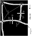
- FIGs. 3A-3C show an implementation example in accordance with one or more embodiments of the invention.
- the table (308) includes hand-drawn stokes that form the rows and columns.
- One or more cells of the table (308) may include text.
- the hand-drawn table (308) may be drawn at an angle. In other words, the table (308) is not aligned with the standard coordinate system (399) for the image (306).
- FIG. 3B shows the image (310) after it has been converted to a mask. Moreover, a custom coordinate system (312) has been established. This custom coordinate system (312) has axes that are better align with the rows and columns of the table (308) than the standard coordinate system (399).
- FIG. 3C shows a partial skeleton graph (314) for the table.
- the skeleton graph (314) includes a set of edges (395) and vertices that represent the hand-drawn table.
- Each edge (395) corresponds to a stroke (316), or a portion of a stroke, of the hand-drawn table and each vertex may correspond to an intersection (318) of two or more edges (395).
- the edges (395) are separated by the vertices.
- each edge (395) contains a path of pixels from one end of the stroke (316) to the other end of the stroke (316), located approximately at the center of the stroke.
- the width of the path/edge is 1 pixel.
- FIGs. 4A and 4B show an implementation example in accordance with one or more embodiments of the invention.
- FIG. 4A shows the mask and skeleton graph of a hand-drawn table (402) similar to the image (310) and skeleton graph (314) of hand-drawn table (308), as discussed above in reference to FIGS. 3A - 3C .
- the method of determining the typesetness score of a hand-drawn table, as discussed above in reference to FIG. 2 is applied to the hand-drawn table (402).
- FIG. 4B shows a histogram (403) as described above in reference to FIG. 2 .
- the histogram (403) is generated after determining the angle for each edge and the length for each edge of the skeleton graph for the hand-drawn table (402).
- the x-axis of the histogram (403) corresponds to the clusters (406) of edges. Specifically, each cluster has edges with the same or similar angles.
- the y-axis of the histogram (403) corresponds to the cluster lengths (404) for each cluster (406).
- the cluster length for a cluster is the sum of the lengths of the edges in the cluster.
- the top two cluster lengths are used to calculate the typesetness score for the hand-drawn table (402).
- the top two cluster lengths are associated with edges having angles that equal (or approximately equal) 0 or 1 degrees.
- the sum of these top two cluster lengths is 26,297.
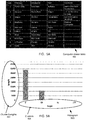
- FIGs. 5A and 5B show an implementation example in accordance with one or more embodiments of the invention.
- FIG. 5A shows the mask and skeleton graph for an image with a table (502).
- the image is a scan of a hardcopy document (i.e., table (502) was visible in the hardcopy document).
- the table (502) was generated by a computer and thus closely matches the template table.
- FIG. 5B shows a histogram (503), as described above in reference to FIG. 2 , for table (502).
- the histogram (503) is generated after determining the angle for each edge and the length for each edge in the skeleton graph for the table (502).
- the x-axis of the histogram (503) corresponds to the clusters (506) of edges. Specifically, each cluster has edges with the same or similar angles.
- the y-axis of the histogram (503) corresponds to the cluster lengths (504) for each cluster (506).
- the cluster length for a cluster is the sum of the lengths of the edges in the cluster.
- the top two cluster lengths are used to calculate the typesetness score for the table (502).
- the top two cluster lengths are associated with edges having angles that equal (or approximately equal) 0 or 90 degrees.
- the sum of these top two cluster lengths is 44,349.
- the total sum of the lengths of all edges from all clusters is 44,762.
- Embodiments of the invention may be implemented on virtually any type of computing system, regardless of the platform being used.
- the computing system may be one or more mobile devices (e.g. , laptop computer, smart phone, personal digital assistant, tablet computer, or other mobile device), desktop computers, servers, blades in a server chassis, or any other type of computing device or devices that includes at least the minimum processing power, memory, and input and output device(s) to perform one or more embodiments of the invention.
- the computing system (600) may include one or more computer processor(s) (602), associated memory (604) (e.g., random access memory (RAM), cache memory, flash memory, etc.
- RAM random access memory
- flash memory etc.
- the computer processor(s) (602) may be an integrated circuit for processing instructions.
- the computer processor(s) may be one or more cores, or micro-cores of a processor.
- the computing system (600) may also include one or more input device(s) (610), such as a touchscreen, keyboard, mouse, microphone, touchpad, electronic pen, or any other type of input device.
- the computing system (600) may include one or more output device(s) (608), such as a screen (e.g., a liquid crystal display (LCD), a plasma display, touchscreen, cathode ray tube (CRT) monitor, projector, or other display device), a printer, external storage, or any other output device.
- a screen e.g., a liquid crystal display (LCD), a plasma display, touchscreen, cathode ray tube (CRT) monitor, projector, or other display device
- One or more of the output device(s) may be the same or different from the input device(s).
- the computing system (600) may be connected to a network (612) (e.g., a local area network (LAN), a wide area network (WAN) such as the Internet, mobile network, or any other type of network) via a network interface connection (not shown).
- LAN local area network
- WAN wide area network
- the input and output device(s) may be locally or remotely (e.g ., via the network (612)) connected to the computer processor(s) (602), memory (604), and storage device(s) (606).
- the computer processor(s) (602), memory (604), and storage device(s) (606) may take other forms.
- Software instructions in the form of computer program to perform embodiments of the invention may be stored, in whole or in part, temporarily or permanently, on a computer readable medium such as a CD, DVD, storage device, a diskette, a tape, flash memory, physical memory, or any other computer readable storage medium.
- the software instructions may correspond to computer readable program code that when executed by a processor(s), is configured to perform embodiments of the invention.
- one or more elements of the aforementioned computing system (600) may be located at a remote location and be connected to the other elements over a network (612).
- one or more embodiments of the invention may be implemented on a distributed system having a plurality of nodes, where each portion of the invention may be located on a different node within the distributed system.
- the node corresponds to a distinct computing device.
- the node may correspond to a computer processor with associated physical memory.
- the node may alternatively correspond to a computer processor or micro-core of a computer processor with shared memory and/or resources.
Landscapes
- Engineering & Computer Science (AREA)
- Theoretical Computer Science (AREA)
- Physics & Mathematics (AREA)
- General Physics & Mathematics (AREA)
- Computer Vision & Pattern Recognition (AREA)
- Data Mining & Analysis (AREA)
- Artificial Intelligence (AREA)
- Multimedia (AREA)
- Databases & Information Systems (AREA)
- Evolutionary Computation (AREA)
- General Engineering & Computer Science (AREA)
- Software Systems (AREA)
- General Health & Medical Sciences (AREA)
- Health & Medical Sciences (AREA)
- Computing Systems (AREA)
- Life Sciences & Earth Sciences (AREA)
- Bioinformatics & Cheminformatics (AREA)
- Bioinformatics & Computational Biology (AREA)
- Evolutionary Biology (AREA)
- Medical Informatics (AREA)
- Audiology, Speech & Language Pathology (AREA)
- Computational Linguistics (AREA)
- Computer Graphics (AREA)
- Geometry (AREA)
- Image Analysis (AREA)
- Processing Or Creating Images (AREA)
- Character Discrimination (AREA)
- Image Processing (AREA)
Applications Claiming Priority (1)
| Application Number | Priority Date | Filing Date | Title |
|---|---|---|---|
| US15/638,860 US10452952B2 (en) | 2017-06-30 | 2017-06-30 | Typesetness score for a table |
Publications (1)
| Publication Number | Publication Date |
|---|---|
| EP3422251A1 true EP3422251A1 (fr) | 2019-01-02 |
Family
ID=62165298
Family Applications (1)
| Application Number | Title | Priority Date | Filing Date |
|---|---|---|---|
| EP18168452.3A Withdrawn EP3422251A1 (fr) | 2017-06-30 | 2018-04-20 | Score de composition pour une table |
Country Status (4)
| Country | Link |
|---|---|
| US (1) | US10452952B2 (fr) |
| EP (1) | EP3422251A1 (fr) |
| JP (1) | JP7219011B2 (fr) |
| CN (1) | CN109214266A (fr) |
Families Citing this family (2)
| Publication number | Priority date | Publication date | Assignee | Title |
|---|---|---|---|---|
| US10679049B2 (en) * | 2017-09-29 | 2020-06-09 | Konica Minolta Laboratory U.S.A., Inc. | Identifying hand drawn tables |
| JP7683253B2 (ja) * | 2021-03-12 | 2025-05-27 | 株式会社リコー | 表示装置、プログラム、変換方法、表示システム |
Citations (3)
| Publication number | Priority date | Publication date | Assignee | Title |
|---|---|---|---|---|
| US5392130A (en) * | 1993-11-24 | 1995-02-21 | Xerox Corporation | Analyzing an image showing a row/column representation |
| US20070140566A1 (en) * | 2005-12-21 | 2007-06-21 | Microsoft Corporation | Framework for detecting a structured handwritten object |
| US20170148140A1 (en) * | 2015-11-25 | 2017-05-25 | Konica Minolta Laboratory U.S.A., Inc. | Offsetting rotated tables in images |
Family Cites Families (5)
| Publication number | Priority date | Publication date | Assignee | Title |
|---|---|---|---|---|
| JP3096481B2 (ja) * | 1991-02-22 | 2000-10-10 | グローリー工業株式会社 | 帳票類の種類判別方法 |
| US5448692A (en) * | 1991-03-27 | 1995-09-05 | Ricoh Company, Ltd. | Digital image processing device involving processing of areas of image, based on respective contour line traces |
| US8634645B2 (en) * | 2008-03-28 | 2014-01-21 | Smart Technologies Ulc | Method and tool for recognizing a hand-drawn table |
| US8649600B2 (en) * | 2009-07-10 | 2014-02-11 | Palo Alto Research Center Incorporated | System and method for segmenting text lines in documents |
| US10467464B2 (en) * | 2016-06-07 | 2019-11-05 | The Neat Company, Inc. | Document field detection and parsing |
-
2017
- 2017-06-30 US US15/638,860 patent/US10452952B2/en active Active
-
2018
- 2018-04-05 JP JP2018073128A patent/JP7219011B2/ja active Active
- 2018-04-20 EP EP18168452.3A patent/EP3422251A1/fr not_active Withdrawn
- 2018-06-29 CN CN201810722352.6A patent/CN109214266A/zh active Pending
Patent Citations (3)
| Publication number | Priority date | Publication date | Assignee | Title |
|---|---|---|---|---|
| US5392130A (en) * | 1993-11-24 | 1995-02-21 | Xerox Corporation | Analyzing an image showing a row/column representation |
| US20070140566A1 (en) * | 2005-12-21 | 2007-06-21 | Microsoft Corporation | Framework for detecting a structured handwritten object |
| US20170148140A1 (en) * | 2015-11-25 | 2017-05-25 | Konica Minolta Laboratory U.S.A., Inc. | Offsetting rotated tables in images |
Non-Patent Citations (1)
| Title |
|---|
| TING A ET AL: "Form recognition using linear structure", PATTERN RECOGNITION, ELSEVIER, GB, vol. 32, no. 4, 1 April 1999 (1999-04-01), pages 645 - 656, XP004157536, ISSN: 0031-3203, DOI: 10.1016/S0031-3203(98)00106-X * |
Also Published As
| Publication number | Publication date |
|---|---|
| JP2019040585A (ja) | 2019-03-14 |
| JP7219011B2 (ja) | 2023-02-07 |
| US20190005352A1 (en) | 2019-01-03 |
| CN109214266A (zh) | 2019-01-15 |
| US10452952B2 (en) | 2019-10-22 |
Similar Documents
| Publication | Publication Date | Title |
|---|---|---|
| US9697423B1 (en) | Identifying the lines of a table | |
| US10331949B2 (en) | Splitting merged table cells | |
| US9842251B2 (en) | Bulleted lists | |
| WO2019119966A1 (fr) | Procédé de traitement d'image de texte, dispositif, équipement et support d'informations | |
| US10403040B2 (en) | Vector graphics rendering techniques | |
| CN112232315B (zh) | 文本框检测方法、装置、电子设备和计算机存储介质 | |
| CN101807179B (zh) | 信息处理器以及信息处理方法 | |
| CN107038441B (zh) | 书写板检测和校正 | |
| US10083218B1 (en) | Repairing tables | |
| US9865038B2 (en) | Offsetting rotated tables in images | |
| CN113657396B (zh) | 训练方法、译文展示方法、装置、电子设备以及存储介质 | |
| US9934431B2 (en) | Producing a flowchart object from an image | |
| US10452952B2 (en) | Typesetness score for a table | |
| US10410386B2 (en) | Table cell validation | |
| US8869026B2 (en) | Using a layout engine to display an overflowed textbox | |
| US10163004B2 (en) | Inferring stroke information from an image | |
| US9785856B2 (en) | Repairing holes in images | |
| US10679049B2 (en) | Identifying hand drawn tables | |
| US10268920B2 (en) | Detection of near rectangular cells | |
| US9977956B2 (en) | Selecting primary groups during production of a flowchart object from an image | |
| US10410052B2 (en) | Stroke based skeletonizer | |
| US20140354627A1 (en) | Rendering a 3d shape | |
| CN108509955B (zh) | 用于字符识别的方法、系统和非瞬时计算机可读介质 | |
| US10579893B2 (en) | Inferring stroke information from an image | |
| CN118366180A (zh) | 签章位置确定方法、装置以及电子设备 |
Legal Events
| Date | Code | Title | Description |
|---|---|---|---|
| PUAI | Public reference made under article 153(3) epc to a published international application that has entered the european phase |
Free format text: ORIGINAL CODE: 0009012 |
|
| AK | Designated contracting states |
Kind code of ref document: A1 Designated state(s): AL AT BE BG CH CY CZ DE DK EE ES FI FR GB GR HR HU IE IS IT LI LT LU LV MC MK MT NL NO PL PT RO RS SE SI SK SM TR |
|
| AX | Request for extension of the european patent |
Extension state: BA ME |
|
| 17P | Request for examination filed |
Effective date: 20190513 |
|
| RBV | Designated contracting states (corrected) |
Designated state(s): AL AT BE BG CH CY CZ DE DK EE ES FI FR GB GR HR HU IE IS IT LI LT LU LV MC MK MT NL NO PL PT RO RS SE SI SK SM TR |
|
| RIC1 | Information provided on ipc code assigned before grant |
Ipc: G06K 9/00 20060101AFI20190820BHEP Ipc: G06K 9/46 20060101ALI20190820BHEP Ipc: G06K 9/32 20060101ALI20190820BHEP Ipc: G06K 9/62 20060101ALI20190820BHEP |
|
| RIC1 | Information provided on ipc code assigned before grant |
Ipc: G06K 9/00 20060101AFI20190823BHEP Ipc: G06K 9/46 20060101ALI20190823BHEP Ipc: G06K 9/32 20060101ALI20190823BHEP Ipc: G06K 9/62 20060101ALI20190823BHEP |
|
| 17Q | First examination report despatched |
Effective date: 20201001 |
|
| STAA | Information on the status of an ep patent application or granted ep patent |
Free format text: STATUS: THE APPLICATION HAS BEEN WITHDRAWN |
|
| 18W | Application withdrawn |
Effective date: 20201113 |