EP3422385B1 - Appareil de rétroaction de signal - Google Patents
Appareil de rétroaction de signal Download PDFInfo
- Publication number
- EP3422385B1 EP3422385B1 EP17177920.0A EP17177920A EP3422385B1 EP 3422385 B1 EP3422385 B1 EP 3422385B1 EP 17177920 A EP17177920 A EP 17177920A EP 3422385 B1 EP3422385 B1 EP 3422385B1
- Authority
- EP
- European Patent Office
- Prior art keywords
- sliding plate
- signal feedback
- feedback apparatus
- microswitch
- linkage
- Prior art date
- Legal status (The legal status is an assumption and is not a legal conclusion. Google has not performed a legal analysis and makes no representation as to the accuracy of the status listed.)
- Active
Links
Images


Classifications
-
- H—ELECTRICITY
- H01—ELECTRIC ELEMENTS
- H01H—ELECTRIC SWITCHES; RELAYS; SELECTORS; EMERGENCY PROTECTIVE DEVICES
- H01H71/00—Details of the protective switches or relays covered by groups H01H73/00 - H01H83/00
- H01H71/10—Operating or release mechanisms
- H01H71/12—Automatic release mechanisms with or without manual release
- H01H71/46—Automatic release mechanisms with or without manual release having means for operating auxiliary contacts additional to the main contacts
- H01H71/465—Self-contained, easily replaceable microswitches
-
- H—ELECTRICITY
- H01—ELECTRIC ELEMENTS
- H01H—ELECTRIC SWITCHES; RELAYS; SELECTORS; EMERGENCY PROTECTIVE DEVICES
- H01H71/00—Details of the protective switches or relays covered by groups H01H73/00 - H01H83/00
- H01H71/10—Operating or release mechanisms
- H01H71/12—Automatic release mechanisms with or without manual release
- H01H71/46—Automatic release mechanisms with or without manual release having means for operating auxiliary contacts additional to the main contacts
- H01H71/462—Automatic release mechanisms with or without manual release having means for operating auxiliary contacts additional to the main contacts housed in a separate casing, juxtaposed to and having the same general contour as the main casing
-
- H—ELECTRICITY
- H01—ELECTRIC ELEMENTS
- H01H—ELECTRIC SWITCHES; RELAYS; SELECTORS; EMERGENCY PROTECTIVE DEVICES
- H01H73/00—Protective overload circuit-breaking switches in which excess current opens the contacts by automatic release of mechanical energy stored by previous operation of a hand reset mechanism
- H01H73/02—Details
- H01H73/06—Housings; Casings; Bases; Mountings
- H01H73/08—Plug-in housings
-
- H—ELECTRICITY
- H01—ELECTRIC ELEMENTS
- H01H—ELECTRIC SWITCHES; RELAYS; SELECTORS; EMERGENCY PROTECTIVE DEVICES
- H01H85/00—Protective devices in which the current flows through a part of fusible material and this current is interrupted by displacement of the fusible material when this current becomes excessive
- H01H85/02—Details
- H01H85/30—Means for indicating condition of fuse structurally associated with the fuse
- H01H85/303—Movable indicating elements
- H01H85/306—Movable indicating elements acting on an auxiliary switch or contact
-
- H—ELECTRICITY
- H01—ELECTRIC ELEMENTS
- H01H—ELECTRIC SWITCHES; RELAYS; SELECTORS; EMERGENCY PROTECTIVE DEVICES
- H01H85/00—Protective devices in which the current flows through a part of fusible material and this current is interrupted by displacement of the fusible material when this current becomes excessive
- H01H85/54—Protective devices wherein the fuse is carried, held, or retained by an intermediate or auxiliary part removable from the base, or used as sectionalisers
Definitions
- the present invention is related to a signal feedback apparatus, in particular, to signal feedback apparatus used in a surge protection device (SPD).
- SPD surge protection device
- a common surge protection device typically comprises an element of Metal Oxide Varistor (MOV) (i.e., a voltage dependent resistor).
- MOV Metal Oxide Varistor
- the surge protection device typically includes a trip mechanism.
- the trip mechanism is in series connection with the voltage dependent resistor such that when the temperature increases, the voltage dependent resistor is disengaged from the circuit.
- a currently existing SPD telesignaling device typically includes a microswitch installed therein for each level.
- these microswitches are connected to the telesignaling terminal block via corresponding circuits such that the mechanism moves through actions on each microswitch.
- Each level performs action independently, and the device is of complicated structure while requiring greater number of components; consequently, its manufacturing process is complicated in practice.
- US 2002 0 139 650 A1 relates to a service switching device of the cap type, and has an auxiliary switch which contains a microswitch and is fitted on a rear narrow face.
- the service switching device has a groove or strip running parallel to the narrow face on each of the broad faces adjacent to the rear narrow face wall.
- Wall sections are integrally formed on the rear wall of the auxiliary switch housing, project parallel to the broad faces in the direction of the narrow face, and are matched to the grooves or strips, such that the auxiliary switch housing can be mounted on the service switching device by pushing in from the front towards the mounting plane, with the microswitch at right angles to the mounting plane on the narrow face, and with the projections or strips which are integrally formed on the wall sections sliding in the grooves or strips.
- the present invention provides a signal feedback apparatus capable of utilizing the opening and closing of a microswitch to achieve the telesignaling monitoring on the states of the functional modules.
- the present invention provides a signal feedback apparatus according to claim 1.
- the telesignaling linkage member comprises a linkage shaft, the linkage shaft includes a driving oblique surface, and the sliding plate includes a driven oblique surface such that when the functional rotating member presses onto the protruding column, the driven oblique surface of the sliding plate is blocked by the driving oblique surface of the linkage shaft.
- the driving oblique surface pushes the driven oblique surface such that the sliding plate moves along the sliding slot to press onto the microswitch.
- the arrangement of the driven oblique surface and driving oblique surface allow the telesignaling linkage member sliding member to slide more stably.
- a resultant force of all of the sliding plate springs is smaller than the elastic force of one single linkage shaft spring. Accordingly, it is able to ensure that after the tripping of the SPD at any level, the signal feedback apparatus is able to send out signal in order to ensure that each tripping is effectively fed back to the control end; therefore, the safety and reliability of SPD are increased while the number of component required is reduced.
- the signal feedback apparatus includes a top cover, and the top cover is of a U-shape plugging socket.
- the inner wall of the U-shape plugging socket includes a locking slot
- the electrical unit includes an outer casing
- the outer casing includes a latch such that when the electrical unit is inserted onto the base, the latch is locked onto the locking slot at the inner wall of the U-shape socket. Therefore, the connection between the signal feedback apparatus and the electrical unit is convenient and fast, which is also able to prevent the electrical unit from loose connection or disengagement; consequently, the product safety is increased.
- the base includes an electrical connector
- the electrical connector includes a metal clamp and a lead wire.
- the metal clamp and the lead wire are soldered onto each other.
- the metal clamp is clamped onto the first electrical connection pin and the second electrical connection pin of the tripping mechanism in order to form a conductive circuit.
- the base includes a limiting point
- the linkage shaft includes a protrusion such that when the linkage shaft is installed inside the base, the protrusion is locked onto the limiting portion in order to prevent the linkage shaft from being ejected by the spring after the installation thereof.
- the signal feedback apparatus of the present invention uses one microswitch only, and it is able to utilize one sliding plate for linking surge protection modules of multiple levels together.
- Each level is provided with a telesignaling linkage shaft linked to the sliding plate and the surge protection module such that when the surge protection module of any one level is of malfunctioned tripping, the telesignaling device is able to send out signals.
- the present invention utilizes the mechanical connection structure of independent linkage for each level such that the mechanical connection is table, the component quantity required is small, the manufacturing process in practice is facilitated and the cost is relatively lower.
- the present invention is able to ensure that each tripping can be effectively fed back to the control end in order to increase the safety and reliability of a SPD.
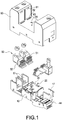
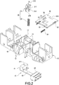
- the present invention provides a signal feedback apparatus, which can be a socket base, comprising a base 10, a telesignaling linkage member 20, a sliding plate 30 and a switch module 40.
- the base 10 is generally of an elongated shape and includes a plurality of hooks 11 formed at a middle region thereof. Each hook 11 is arranged spaced apart from each other, and a sliding slot 12 is formed at a lower edge among each hook 11.
- One side of the hook 11 is formed of an end surface 13.
- the middle region of the base 10 includes an installation hole 14 formed thereon.
- the quantity of the installation hole 14 is two.
- One side of each one of the installation holes 14 includes a groove formed thereon, and a top edge of the groove is formed of a limiting point 15.
- the base 10 at the rear end of the sliding slot 12 is formed of a blocking wall 16.
- the two side regions of the base 10 include a plurality of receiving slots 17 formed thereon respectively.
- the telesignaling linkage member 20 is received inside the installation hole 14.
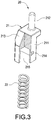
- the quantity of the telesignaling linkage member 20 is two, and each telesignaling linkage member 20 comprises a linkage shaft 21 and a linkage shaft spring 22.
- the linkage shaft 21 includes a cylindrical member 211 and a protruding column 212 extended upward from the top end of the cylindrical member 211.
- One side of the cylindrical member 211 is formed of a driving oblique surface 213 and another side thereof is formed of a protrusion 214.
- the internal of the cylindrical member 211 is formed of an inner hole 215.
- the linkage shaft spring 22 is received inside the inner hole 215 and the installation hole 14.
- the protrusion 214 is received inside the aforementioned groove.
- the limiting point 15 is used for blocking the protrusion 214 in order to ensure that the linkage shaft 21 is not ejected by the linkage shaft spring 22 after the installation thereof.
- the sliding plate 30 is generally a rectangular plate.
- the middle region of the sliding plate 30 and the front side thereof include a rectangular hole 31 and a notch 31A formed thereon respectively.
- the rectangular hole 31 and the notch 31A include a side wall formed of a driven oblique surface 311 respectively.
- the bottom surface of the sliding plate 30 includes a microswitch triggering piece 32 protruded therefrom.
- Two sides of the rear of the sliding plate 30 include a securement column 33 formed thereon respectively and provided for a sliding plate spring 34 to be mounted thereon; wherein a resultant force of the two sliding plate springs 34 is smaller than the elastic force of one single linkage shaft spring 22.
- the two left and right sides of the sliding plate 30 include a positioning retainer 35 formed thereon respectively.
- the sliding plate 30 is moveably received inside the sliding slot 12 and uses the positioning retainer 35 to abut against the end surface 13.
- One end of the sliding plate spring 34 abuts against the blocking wall 16 in order to allow the blocking wall 16 to provide a continuous push force to the sliding plate 14.
- one side the rectangular hole 31 is formed of an anti-misfit hole 36.
- the switch module 40 s installed at a corner of the base 10.
- the switch module 40 comprises a microswitch 41, a circuit board 42, a terminal block 43 and a telesignaling connection terminal 44.
- the microswitch 41 includes a microswitch button 411.
- the microswitch 41 and the terminal block 43 are soldered onto the circuit board 42, and the microswitch 41 is arranged corresponding to the aforementioned microswitch triggering piece 32 such that the microswitch 41 can be operably opened or closed based on the movement of the sliding block 30.
- the signal feedback apparatus of the present invention further comprises a plurality of electrical connectors 50.
- Each electrical connector 50 is installed inside each receiving slot 17 of the base 10.
- Each electrical connector 50 comprises a lead wire 51 and a metal clamp 52 electrically connected to the lead wire 51.
- the signal feedback apparatus of the present invention further comprises a top cover 60 for covering onto the base 10 correspondingly.
- the top cover 60 includes a U-shape socket opening, and a locking slot 61 is formed at corresponding location of the two side plates respectively.
- the bottom plate is formed of an insertion slot 62 corresponding to the aforementioned metal clamp 52; furthermore, a through hole 63 is formed at a location corresponding to the aforementioned anti-misfit insertion hole 36; moreover, an perforation 64 is formed at a location corresponding to the aforementioned protruding column 212 in order to allow the protruding column 212 to penetrate therethrough.
- the signal feedback apparatus of the present invention can be provided for uses of an electronic unit 8, such as a SPD, a terminal block or a relay etc.
- an electronic unit 8 such as a SPD, a terminal block or a relay etc.
- a two-level SPD is used for illustration, and it comprises an outer casing 81, and a latch 82 formed at side walls of the outer casing 81 respectively.
- the internal of the outer casing 81 can be installed with a voltage dependent resistor (not shown in the figures), and the bottom end of the outer casing 81 includes a first electrical connection pin 83 and a second electrical connection pin 84 extended therefrom.
- the central region of the electrical unit 8 includes a functional rotating member 85.
- the electrical unit 8 is placed into the opening slot of the top cover 60, and each latch 82 is locked onto the corresponding locking slot 61 respectively.
- the first electrical connection pin 83 and the second electrical connection pin 84 are inserted into the insertion slot 62 in order to be clamped by the metal clamp 52 of each electrical connector 50 and to form a conductive circuit.
- the functional rotating member 85 performs the downward press action corresponding to the protruding column 212 of the linkage shaft 21.
- FIG 7 shows a normal working state of the voltage dependent resistor.
- the linkage shaft spring 22 is under the maximum compression state.
- the driven oblique surface 311 of the sliding plate 30 is blocked at the right end of the sliding slot 12 by the driven oblique surface 213 of the linkage shaft 21.
- the microswitch triggering piece 32 on the sliding plate 30 has no effect on the microswitch button 411, and the microswitch button 411 is under a naturally extended state elastically, indicating the voltage dependent resistor is under a normal working state.
- FIG 8 shows a tripped state of the voltage dependent resistor.
- the functional rotating member 85 rotates counterclockwise such that the protruding column 212 of the linkage shaft 21 is released, and the functional rotating shaft 85 generates a release effect on the linkage shaft 21.
- the protruding column 212 of the linkage shaft 21 is provided with an upward movement space, and the linkage shaft 21 bounces upward under the push effect of the linkage shaft spring 22, indicating that the voltage dependent resistor is under a tripped state, i.e. a malfunction state.
- the driving oblique surface 213 drives the sliding plate 30 to move leftward along the sliding slot 12 via the driven oblique surface 311.
- the sliding plate 30 When the linkage shaft 21 is completely extended elastically, the sliding plate 30 is of a stroke with the maximum movement and the sliding plate spring 34 is compressed such that the microswitch triggering piece 32 presses downward on the microswitch button 411. Since the resultant force of the two sliding plate spring 34 is smaller than the elastic force of one single linkage shaft spring 22, the use of only one microswitch 41 and one sliding plate 30 is sufficient to allow the signal feedback apparatus of the present invention to send out a failure warning signal to the control system after the SPD of any level is tripped in order to ensure that every trip is effectively fed back to the control end. Therefore, it is able to alert the maintenance personnel to readily replace the failed SPD such that the safety and reliability of SPD is increased while the apparatus is of small quantity of components, reduced size, facilitated for manufacturing in practice and relatively lower cost.
- the signal feedback apparatus of the present invention is able to achieve the expected purpose of use and to overcome the drawbacks of prior arts.
- the present invention is of novelty and inventive step to comply with the patentability of invention patents.
Landscapes
- Push-Button Switches (AREA)
Claims (12)
- Un appareil de rétroaction de signal comprenant:une base (10);un élément de liaison de télésignalisation (20) installé de manière mobile sur la base (10);une plaque coulissante (30) installée en correspondance avec l'élément de liaison de télésignalisation (20) et configurée pour générer un mouvement conjointement avec l'élément de liaison de télésignalisation (20); etun module de commutation (40) comprenant un microcommutateur (41); le microcommutateur (41) étant agencé pour correspondre à la plaque coulissante (30) et étant configuré pour ouvrir ou fermer de manière fonctionnelle le microcommutateur (41) en fonction du mouvement de la plaque coulissante (30),caractérisé en ce que la plaque coulissante (30) comporte un trou rectangulaire (31) et une encoche (31A) formée sur celui-ci, l'élément de télésignalisation (20) comprenant deux arbres de liaison (21), et les arbres de liaison (21) pénétrant à travers le trou rectangulaire (31) et l'encoche (31A) respectivement,dans lequel le trou rectangulaire (31) et l'encoche (31A) comprennent une surface oblique entraînée (311) formée dans une paroi latérale de celle-ci, les arbres de liaison (21) comprenant une surface oblique d'entraînement (213) formées dessus, respectivement, et chacune des surfaces obliques d'entraînement (213) est en prise avec chacune des surfaces obliques entrainées correspondantes.
- L'appareil de rétroaction de signal selon la revendication 1, dans lequel la base (10) comprend une pluralité de crochets (11) formés sur celle-ci; une fente coulissante (12) étant formée au niveau d'un bord inférieur de chaque crochet au sein de la pluralité de crochets (11); la plaque coulissante (30) est configurée pour recevoir de manière mobile à l'intérieur de la fente coulissante (12).
- L'appareil de rétroaction de signal selon la revendication 2, dans lequel un côté du crochet (11) est formé d'une surface d'extrémité (13), un côté de la plaque coulissante (30) est formé d'un dispositif de retenue de positionnement (35); le dispositif de retenue de positionnement (35) butant contre la surface d'extrémité (13).
- L'appareil de rétroaction de signal selon l'une quelconque des revendications 1 à 3, dans lequel la base (10) comprend un point limite (15), l'élément de liaison de télésignalisation (20) comprend une saillie (214) telle que lorsque l'arbre de liaison (21) est placée à l'intérieur de la base (10), la saillie (214) se verrouille sur le point limite (15).
- L'appareil de rétroaction de signal selon l'une quelconque des revendications 1 à 4, dans lequel la base (10) comprend un trou d'installation (14), et l'arbre de liaison (21) comprend un élément cylindrique (211) et une colonne en saillie (212) s'étendant à partir de l'élément cylindrique (211); l'élément cylindrique (211) étant reçu à l'intérieur du trou d'installation (14).
- L'appareil de rétroaction de signal selon la revendication 5, dans lequel l'élément de télésignalisation (20) comprend en outre un ressort d'arbre de liaison (22), l'élément cylindrique (211) étant formé d'un trou intérieur (215) au niveau de son intérieur; le ressort d'arbre de liaison (22) est logé à l'intérieur du trou intérieur (215) et du trou d'installation (14).
- L'appareil de rétroaction de signal selon la revendication 6, dans lequel la plaque coulissante (30) comprend deux colonnes de fixation (33) formées sur celle-ci, et chacune des colonnes de fixation est prévue pour le montage d'un ressort de plaque coulissante (34) ; une force résultante des ressorts de la plaque coulissante (34) étant inférieure à la force élastique d'une seule unité du ressort de l'arbre de liaison (22).
- L'appareil de rétroaction de signal selon la revendication 7, dans lequel la base (10) est formée d'une paroi de blocage (16), et une extrémité de chacun des ressorts de la plaque coulissante (34) bute contre la paroi de blocage (16).
- L'appareil de rétroaction de signal selon la revendication 1, dans lequel la plaque coulissante (30) comprend un trou anti-inadapté (36) formé sur celle-ci, et le trou anti-inadapté (36) est disposé sur un côté du trou rectangulaire (31).
- L'appareil de rétroaction de signal selon l'une quelconque des revendications 1 à 9, dans lequel le microcommutateur (41) comprend un bouton de microcommutateur (411) et la plaque coulissante (30) comprend une pièce de déclenchement du microcommutateur (32) telle que la pièce de déclenchement du microcommutateur (32)) est utilisé pour appuyer ou relâcher le bouton du microcommutateur (411).
- L'appareil de rétroaction de signal selon l'une quelconque des revendications 1 à 10, comprenant en outre un connecteur électrique (50); le connecteur électrique (50) comprenant un fil conducteur (51) et une pince métallique (52); la base (10) comprend une fente de réception (17) y formée; le connecteur électrique (50) étant inséré dans la fente de réception correspondante (17) en vue de la fixation avec celle-ci, et la pince métallique (52) étant soudée sur le fil conducteur (51).
- L'appareil de rétroaction de signal selon l'une quelconque des revendications 1 à 11, comprenant en outre un couvercle supérieur (60); le couvercle supérieur (60) comprenant une ouverture à douille en forme de U et la paroi latérale intérieure de l'ouverture à douille en forme de U comprenant une fente de verrouillage (61).
Priority Applications (1)
| Application Number | Priority Date | Filing Date | Title |
|---|---|---|---|
| EP17177920.0A EP3422385B1 (fr) | 2017-06-26 | 2017-06-26 | Appareil de rétroaction de signal |
Applications Claiming Priority (1)
| Application Number | Priority Date | Filing Date | Title |
|---|---|---|---|
| EP17177920.0A EP3422385B1 (fr) | 2017-06-26 | 2017-06-26 | Appareil de rétroaction de signal |
Publications (2)
| Publication Number | Publication Date |
|---|---|
| EP3422385A1 EP3422385A1 (fr) | 2019-01-02 |
| EP3422385B1 true EP3422385B1 (fr) | 2019-06-12 |
Family
ID=59227566
Family Applications (1)
| Application Number | Title | Priority Date | Filing Date |
|---|---|---|---|
| EP17177920.0A Active EP3422385B1 (fr) | 2017-06-26 | 2017-06-26 | Appareil de rétroaction de signal |
Country Status (1)
| Country | Link |
|---|---|
| EP (1) | EP3422385B1 (fr) |
Families Citing this family (3)
| Publication number | Priority date | Publication date | Assignee | Title |
|---|---|---|---|---|
| CN109637905B (zh) * | 2019-02-28 | 2024-09-20 | 浙江天正电气股份有限公司 | 一种塑壳断路器的分合闸检测装置 |
| CN110429013B (zh) * | 2019-08-14 | 2024-06-21 | 西安赛诺克新能源科技有限公司 | 一种电池包维修开关 |
| CN111968890B (zh) * | 2020-09-15 | 2025-01-28 | 成都标定科技有限责任公司 | 一种适用于多模式的遥信串联结构 |
Family Cites Families (6)
| Publication number | Priority date | Publication date | Assignee | Title |
|---|---|---|---|---|
| JPS61184258U (fr) * | 1985-05-08 | 1986-11-17 | ||
| JPH01204328A (ja) * | 1988-02-10 | 1989-08-16 | Hitachi Ltd | 回路遮断器 |
| US4926148A (en) * | 1988-10-03 | 1990-05-15 | Heinemann Electric Company | Auxiliary switch retainer for circuit breakers and actuator member |
| JPH0443841U (fr) * | 1990-08-14 | 1992-04-14 | ||
| DE19846219B4 (de) * | 1998-10-07 | 2004-12-23 | Aeg Niederspannungstechnik Gmbh & Co Kg | Stromschalter |
| DE10116001A1 (de) * | 2001-03-30 | 2002-10-02 | Abb Patent Gmbh | Installationsschaltgerät in Sockelbauweise |
-
2017
- 2017-06-26 EP EP17177920.0A patent/EP3422385B1/fr active Active
Non-Patent Citations (1)
| Title |
|---|
| None * |
Also Published As
| Publication number | Publication date |
|---|---|
| EP3422385A1 (fr) | 2019-01-02 |
Similar Documents
| Publication | Publication Date | Title |
|---|---|---|
| EP3240132B1 (fr) | Parasurtenseur du type remplaçable | |
| CN114144953A (zh) | 具有电流隔离的固态断路器 | |
| EP3422370B1 (fr) | Dispositif de protection contre les surtensions et mécanisme de libération et leur base | |
| US10593501B2 (en) | Surge protector and base therof | |
| CN108962699B (zh) | 用于电涌保护器的脱扣机构、底座及电涌保护器 | |
| CN103151226B (zh) | 用于电涌保护设备的壳体及相关的电涌保护设备 | |
| US10529508B2 (en) | Signal feedback apparatus | |
| EP3422385B1 (fr) | Appareil de rétroaction de signal | |
| JP4884531B2 (ja) | 挿入式の少なくとも1つの避雷器を電気的および機械的に収容するためのベース部 | |
| CN106463304A (zh) | 具有至少一个过电压放电器和与该过电压放电器并联、可热触发的、弹簧预张紧的短路开关装置的过电压保护装置 | |
| CN110350501B (zh) | 三相电涌保护装置 | |
| CN106602536A (zh) | 一种电涌保护模块 | |
| KR101000755B1 (ko) | 배리스터 장치 | |
| CN206481053U (zh) | 一种电涌保护模块 | |
| CN206819951U (zh) | 信号反馈装置 | |
| CN219801895U (zh) | 一种浪涌保护器及电源机箱 | |
| JP7335355B2 (ja) | サージ保護デバイスおよびモジュール式サージ保護システム | |
| CN115065010A (zh) | 一种基于电磁力的过载保护装置 | |
| CN211907368U (zh) | 一种热脱扣结构及其采用该结构的浪涌保护器 | |
| CN108962695B (zh) | 信号反馈装置 | |
| CN210490455U (zh) | 一种整体式电涌保护器 | |
| CN112822894B (zh) | 电涌保护模块及电涌保护器 | |
| CN111933370B (zh) | 一种浪涌保护器 | |
| CN220368472U (zh) | 一种新型spd组件 | |
| CN111628487B (zh) | 压敏模块及电涌保护器 |
Legal Events
| Date | Code | Title | Description |
|---|---|---|---|
| PUAI | Public reference made under article 153(3) epc to a published international application that has entered the european phase |
Free format text: ORIGINAL CODE: 0009012 |
|
| STAA | Information on the status of an ep patent application or granted ep patent |
Free format text: STATUS: REQUEST FOR EXAMINATION WAS MADE |
|
| 17P | Request for examination filed |
Effective date: 20180316 |
|
| AK | Designated contracting states |
Kind code of ref document: A1 Designated state(s): AL AT BE BG CH CY CZ DE DK EE ES FI FR GB GR HR HU IE IS IT LI LT LU LV MC MK MT NL NO PL PT RO RS SE SI SK SM TR |
|
| AX | Request for extension of the european patent |
Extension state: BA ME |
|
| GRAJ | Information related to disapproval of communication of intention to grant by the applicant or resumption of examination proceedings by the epo deleted |
Free format text: ORIGINAL CODE: EPIDOSDIGR1 |
|
| STAA | Information on the status of an ep patent application or granted ep patent |
Free format text: STATUS: GRANT OF PATENT IS INTENDED |
|
| GRAP | Despatch of communication of intention to grant a patent |
Free format text: ORIGINAL CODE: EPIDOSNIGR1 |
|
| INTG | Intention to grant announced |
Effective date: 20190215 |
|
| GRAS | Grant fee paid |
Free format text: ORIGINAL CODE: EPIDOSNIGR3 |
|
| GRAA | (expected) grant |
Free format text: ORIGINAL CODE: 0009210 |
|
| STAA | Information on the status of an ep patent application or granted ep patent |
Free format text: STATUS: THE PATENT HAS BEEN GRANTED |
|
| AK | Designated contracting states |
Kind code of ref document: B1 Designated state(s): AL AT BE BG CH CY CZ DE DK EE ES FI FR GB GR HR HU IE IS IT LI LT LU LV MC MK MT NL NO PL PT RO RS SE SI SK SM TR |
|
| REG | Reference to a national code |
Ref country code: GB Ref legal event code: FG4D |
|
| REG | Reference to a national code |
Ref country code: CH Ref legal event code: EP |
|
| REG | Reference to a national code |
Ref country code: AT Ref legal event code: REF Ref document number: 1143664 Country of ref document: AT Kind code of ref document: T Effective date: 20190615 |
|
| REG | Reference to a national code |
Ref country code: DE Ref legal event code: R096 Ref document number: 602017004420 Country of ref document: DE |
|
| REG | Reference to a national code |
Ref country code: IE Ref legal event code: FG4D |
|
| REG | Reference to a national code |
Ref country code: NL Ref legal event code: MP Effective date: 20190612 |
|
| REG | Reference to a national code |
Ref country code: LT Ref legal event code: MG4D |
|
| PG25 | Lapsed in a contracting state [announced via postgrant information from national office to epo] |
Ref country code: AL Free format text: LAPSE BECAUSE OF FAILURE TO SUBMIT A TRANSLATION OF THE DESCRIPTION OR TO PAY THE FEE WITHIN THE PRESCRIBED TIME-LIMIT Effective date: 20190612 Ref country code: SE Free format text: LAPSE BECAUSE OF FAILURE TO SUBMIT A TRANSLATION OF THE DESCRIPTION OR TO PAY THE FEE WITHIN THE PRESCRIBED TIME-LIMIT Effective date: 20190612 Ref country code: LT Free format text: LAPSE BECAUSE OF FAILURE TO SUBMIT A TRANSLATION OF THE DESCRIPTION OR TO PAY THE FEE WITHIN THE PRESCRIBED TIME-LIMIT Effective date: 20190612 Ref country code: HR Free format text: LAPSE BECAUSE OF FAILURE TO SUBMIT A TRANSLATION OF THE DESCRIPTION OR TO PAY THE FEE WITHIN THE PRESCRIBED TIME-LIMIT Effective date: 20190612 Ref country code: FI Free format text: LAPSE BECAUSE OF FAILURE TO SUBMIT A TRANSLATION OF THE DESCRIPTION OR TO PAY THE FEE WITHIN THE PRESCRIBED TIME-LIMIT Effective date: 20190612 Ref country code: NO Free format text: LAPSE BECAUSE OF FAILURE TO SUBMIT A TRANSLATION OF THE DESCRIPTION OR TO PAY THE FEE WITHIN THE PRESCRIBED TIME-LIMIT Effective date: 20190912 |
|
| PG25 | Lapsed in a contracting state [announced via postgrant information from national office to epo] |
Ref country code: RS Free format text: LAPSE BECAUSE OF FAILURE TO SUBMIT A TRANSLATION OF THE DESCRIPTION OR TO PAY THE FEE WITHIN THE PRESCRIBED TIME-LIMIT Effective date: 20190612 Ref country code: GR Free format text: LAPSE BECAUSE OF FAILURE TO SUBMIT A TRANSLATION OF THE DESCRIPTION OR TO PAY THE FEE WITHIN THE PRESCRIBED TIME-LIMIT Effective date: 20190913 Ref country code: BG Free format text: LAPSE BECAUSE OF FAILURE TO SUBMIT A TRANSLATION OF THE DESCRIPTION OR TO PAY THE FEE WITHIN THE PRESCRIBED TIME-LIMIT Effective date: 20190912 Ref country code: LV Free format text: LAPSE BECAUSE OF FAILURE TO SUBMIT A TRANSLATION OF THE DESCRIPTION OR TO PAY THE FEE WITHIN THE PRESCRIBED TIME-LIMIT Effective date: 20190612 |
|
| REG | Reference to a national code |
Ref country code: AT Ref legal event code: MK05 Ref document number: 1143664 Country of ref document: AT Kind code of ref document: T Effective date: 20190612 |
|
| PG25 | Lapsed in a contracting state [announced via postgrant information from national office to epo] |
Ref country code: AT Free format text: LAPSE BECAUSE OF FAILURE TO SUBMIT A TRANSLATION OF THE DESCRIPTION OR TO PAY THE FEE WITHIN THE PRESCRIBED TIME-LIMIT Effective date: 20190612 Ref country code: NL Free format text: LAPSE BECAUSE OF FAILURE TO SUBMIT A TRANSLATION OF THE DESCRIPTION OR TO PAY THE FEE WITHIN THE PRESCRIBED TIME-LIMIT Effective date: 20190612 Ref country code: PT Free format text: LAPSE BECAUSE OF FAILURE TO SUBMIT A TRANSLATION OF THE DESCRIPTION OR TO PAY THE FEE WITHIN THE PRESCRIBED TIME-LIMIT Effective date: 20191014 Ref country code: SK Free format text: LAPSE BECAUSE OF FAILURE TO SUBMIT A TRANSLATION OF THE DESCRIPTION OR TO PAY THE FEE WITHIN THE PRESCRIBED TIME-LIMIT Effective date: 20190612 Ref country code: RO Free format text: LAPSE BECAUSE OF FAILURE TO SUBMIT A TRANSLATION OF THE DESCRIPTION OR TO PAY THE FEE WITHIN THE PRESCRIBED TIME-LIMIT Effective date: 20190612 Ref country code: CZ Free format text: LAPSE BECAUSE OF FAILURE TO SUBMIT A TRANSLATION OF THE DESCRIPTION OR TO PAY THE FEE WITHIN THE PRESCRIBED TIME-LIMIT Effective date: 20190612 Ref country code: EE Free format text: LAPSE BECAUSE OF FAILURE TO SUBMIT A TRANSLATION OF THE DESCRIPTION OR TO PAY THE FEE WITHIN THE PRESCRIBED TIME-LIMIT Effective date: 20190612 |
|
| PG25 | Lapsed in a contracting state [announced via postgrant information from national office to epo] |
Ref country code: ES Free format text: LAPSE BECAUSE OF FAILURE TO SUBMIT A TRANSLATION OF THE DESCRIPTION OR TO PAY THE FEE WITHIN THE PRESCRIBED TIME-LIMIT Effective date: 20190612 Ref country code: SM Free format text: LAPSE BECAUSE OF FAILURE TO SUBMIT A TRANSLATION OF THE DESCRIPTION OR TO PAY THE FEE WITHIN THE PRESCRIBED TIME-LIMIT Effective date: 20190612 Ref country code: IS Free format text: LAPSE BECAUSE OF FAILURE TO SUBMIT A TRANSLATION OF THE DESCRIPTION OR TO PAY THE FEE WITHIN THE PRESCRIBED TIME-LIMIT Effective date: 20191012 |
|
| REG | Reference to a national code |
Ref country code: DE Ref legal event code: R097 Ref document number: 602017004420 Country of ref document: DE |
|
| REG | Reference to a national code |
Ref country code: BE Ref legal event code: MM Effective date: 20190630 |
|
| PG25 | Lapsed in a contracting state [announced via postgrant information from national office to epo] |
Ref country code: MC Free format text: LAPSE BECAUSE OF FAILURE TO SUBMIT A TRANSLATION OF THE DESCRIPTION OR TO PAY THE FEE WITHIN THE PRESCRIBED TIME-LIMIT Effective date: 20190612 |
|
| PLBE | No opposition filed within time limit |
Free format text: ORIGINAL CODE: 0009261 |
|
| STAA | Information on the status of an ep patent application or granted ep patent |
Free format text: STATUS: NO OPPOSITION FILED WITHIN TIME LIMIT |
|
| PG25 | Lapsed in a contracting state [announced via postgrant information from national office to epo] |
Ref country code: IE Free format text: LAPSE BECAUSE OF NON-PAYMENT OF DUE FEES Effective date: 20190626 Ref country code: PL Free format text: LAPSE BECAUSE OF FAILURE TO SUBMIT A TRANSLATION OF THE DESCRIPTION OR TO PAY THE FEE WITHIN THE PRESCRIBED TIME-LIMIT Effective date: 20190612 Ref country code: DK Free format text: LAPSE BECAUSE OF FAILURE TO SUBMIT A TRANSLATION OF THE DESCRIPTION OR TO PAY THE FEE WITHIN THE PRESCRIBED TIME-LIMIT Effective date: 20190612 |
|
| 26N | No opposition filed |
Effective date: 20200313 |
|
| PG25 | Lapsed in a contracting state [announced via postgrant information from national office to epo] |
Ref country code: IS Free format text: LAPSE BECAUSE OF FAILURE TO SUBMIT A TRANSLATION OF THE DESCRIPTION OR TO PAY THE FEE WITHIN THE PRESCRIBED TIME-LIMIT Effective date: 20200224 Ref country code: BE Free format text: LAPSE BECAUSE OF NON-PAYMENT OF DUE FEES Effective date: 20190630 Ref country code: LU Free format text: LAPSE BECAUSE OF NON-PAYMENT OF DUE FEES Effective date: 20190626 |
|
| PG2D | Information on lapse in contracting state deleted |
Ref country code: IS |
|
| PG25 | Lapsed in a contracting state [announced via postgrant information from national office to epo] |
Ref country code: FR Free format text: LAPSE BECAUSE OF NON-PAYMENT OF DUE FEES Effective date: 20190812 |
|
| REG | Reference to a national code |
Ref country code: CH Ref legal event code: PL |
|
| PG25 | Lapsed in a contracting state [announced via postgrant information from national office to epo] |
Ref country code: LI Free format text: LAPSE BECAUSE OF NON-PAYMENT OF DUE FEES Effective date: 20200630 Ref country code: CH Free format text: LAPSE BECAUSE OF NON-PAYMENT OF DUE FEES Effective date: 20200630 |
|
| PG25 | Lapsed in a contracting state [announced via postgrant information from national office to epo] |
Ref country code: CY Free format text: LAPSE BECAUSE OF FAILURE TO SUBMIT A TRANSLATION OF THE DESCRIPTION OR TO PAY THE FEE WITHIN THE PRESCRIBED TIME-LIMIT Effective date: 20190612 |
|
| PG25 | Lapsed in a contracting state [announced via postgrant information from national office to epo] |
Ref country code: MT Free format text: LAPSE BECAUSE OF FAILURE TO SUBMIT A TRANSLATION OF THE DESCRIPTION OR TO PAY THE FEE WITHIN THE PRESCRIBED TIME-LIMIT Effective date: 20190612 Ref country code: HU Free format text: LAPSE BECAUSE OF FAILURE TO SUBMIT A TRANSLATION OF THE DESCRIPTION OR TO PAY THE FEE WITHIN THE PRESCRIBED TIME-LIMIT; INVALID AB INITIO Effective date: 20170626 |
|
| PG25 | Lapsed in a contracting state [announced via postgrant information from national office to epo] |
Ref country code: SI Free format text: LAPSE BECAUSE OF FAILURE TO SUBMIT A TRANSLATION OF THE DESCRIPTION OR TO PAY THE FEE WITHIN THE PRESCRIBED TIME-LIMIT Effective date: 20190612 |
|
| GBPC | Gb: european patent ceased through non-payment of renewal fee |
Effective date: 20210626 |
|
| PG25 | Lapsed in a contracting state [announced via postgrant information from national office to epo] |
Ref country code: GB Free format text: LAPSE BECAUSE OF NON-PAYMENT OF DUE FEES Effective date: 20210626 |
|
| PG25 | Lapsed in a contracting state [announced via postgrant information from national office to epo] |
Ref country code: MK Free format text: LAPSE BECAUSE OF FAILURE TO SUBMIT A TRANSLATION OF THE DESCRIPTION OR TO PAY THE FEE WITHIN THE PRESCRIBED TIME-LIMIT Effective date: 20190612 |
|
| P01 | Opt-out of the competence of the unified patent court (upc) registered |
Effective date: 20230522 |
|
| PGFP | Annual fee paid to national office [announced via postgrant information from national office to epo] |
Ref country code: TR Payment date: 20250409 Year of fee payment: 9 |
|
| PGFP | Annual fee paid to national office [announced via postgrant information from national office to epo] |
Ref country code: DE Payment date: 20250707 Year of fee payment: 9 |
|
| PGFP | Annual fee paid to national office [announced via postgrant information from national office to epo] |
Ref country code: IT Payment date: 20250623 Year of fee payment: 9 |