EP3422461A1 - Blei-säure-akkumulator - Google Patents
Blei-säure-akkumulator Download PDFInfo
- Publication number
- EP3422461A1 EP3422461A1 EP16904625.7A EP16904625A EP3422461A1 EP 3422461 A1 EP3422461 A1 EP 3422461A1 EP 16904625 A EP16904625 A EP 16904625A EP 3422461 A1 EP3422461 A1 EP 3422461A1
- Authority
- EP
- European Patent Office
- Prior art keywords
- separator
- storage battery
- rib
- acid storage
- lead acid
- Prior art date
- Legal status (The legal status is an assumption and is not a legal conclusion. Google has not performed a legal analysis and makes no representation as to the accuracy of the status listed.)
- Withdrawn
Links
Images


Classifications
-
- H—ELECTRICITY
- H01—ELECTRIC ELEMENTS
- H01M—PROCESSES OR MEANS, e.g. BATTERIES, FOR THE DIRECT CONVERSION OF CHEMICAL ENERGY INTO ELECTRICAL ENERGY
- H01M10/00—Secondary cells; Manufacture thereof
- H01M10/06—Lead-acid accumulators
- H01M10/12—Construction or manufacture
-
- H—ELECTRICITY
- H01—ELECTRIC ELEMENTS
- H01M—PROCESSES OR MEANS, e.g. BATTERIES, FOR THE DIRECT CONVERSION OF CHEMICAL ENERGY INTO ELECTRICAL ENERGY
- H01M50/00—Constructional details or processes of manufacture of the non-active parts of electrochemical cells other than fuel cells, e.g. hybrid cells
- H01M50/40—Separators; Membranes; Diaphragms; Spacing elements inside cells
- H01M50/409—Separators, membranes or diaphragms characterised by the material
- H01M50/431—Inorganic material
- H01M50/434—Ceramics
- H01M50/437—Glass
-
- H—ELECTRICITY
- H01—ELECTRIC ELEMENTS
- H01M—PROCESSES OR MEANS, e.g. BATTERIES, FOR THE DIRECT CONVERSION OF CHEMICAL ENERGY INTO ELECTRICAL ENERGY
- H01M10/00—Secondary cells; Manufacture thereof
- H01M10/06—Lead-acid accumulators
- H01M10/08—Selection of materials as electrolytes
-
- H—ELECTRICITY
- H01—ELECTRIC ELEMENTS
- H01M—PROCESSES OR MEANS, e.g. BATTERIES, FOR THE DIRECT CONVERSION OF CHEMICAL ENERGY INTO ELECTRICAL ENERGY
- H01M50/00—Constructional details or processes of manufacture of the non-active parts of electrochemical cells other than fuel cells, e.g. hybrid cells
- H01M50/40—Separators; Membranes; Diaphragms; Spacing elements inside cells
- H01M50/409—Separators, membranes or diaphragms characterised by the material
- H01M50/411—Organic material
- H01M50/414—Synthetic resins, e.g. thermoplastics or thermosetting resins
- H01M50/417—Polyolefins
-
- H—ELECTRICITY
- H01—ELECTRIC ELEMENTS
- H01M—PROCESSES OR MEANS, e.g. BATTERIES, FOR THE DIRECT CONVERSION OF CHEMICAL ENERGY INTO ELECTRICAL ENERGY
- H01M50/00—Constructional details or processes of manufacture of the non-active parts of electrochemical cells other than fuel cells, e.g. hybrid cells
- H01M50/40—Separators; Membranes; Diaphragms; Spacing elements inside cells
- H01M50/409—Separators, membranes or diaphragms characterised by the material
- H01M50/44—Fibrous material
-
- H—ELECTRICITY
- H01—ELECTRIC ELEMENTS
- H01M—PROCESSES OR MEANS, e.g. BATTERIES, FOR THE DIRECT CONVERSION OF CHEMICAL ENERGY INTO ELECTRICAL ENERGY
- H01M50/00—Constructional details or processes of manufacture of the non-active parts of electrochemical cells other than fuel cells, e.g. hybrid cells
- H01M50/40—Separators; Membranes; Diaphragms; Spacing elements inside cells
- H01M50/409—Separators, membranes or diaphragms characterised by the material
- H01M50/446—Composite material consisting of a mixture of organic and inorganic materials
-
- H—ELECTRICITY
- H01—ELECTRIC ELEMENTS
- H01M—PROCESSES OR MEANS, e.g. BATTERIES, FOR THE DIRECT CONVERSION OF CHEMICAL ENERGY INTO ELECTRICAL ENERGY
- H01M50/00—Constructional details or processes of manufacture of the non-active parts of electrochemical cells other than fuel cells, e.g. hybrid cells
- H01M50/40—Separators; Membranes; Diaphragms; Spacing elements inside cells
- H01M50/409—Separators, membranes or diaphragms characterised by the material
- H01M50/449—Separators, membranes or diaphragms characterised by the material having a layered structure
- H01M50/454—Separators, membranes or diaphragms characterised by the material having a layered structure comprising a non-fibrous layer and a fibrous layer superimposed on one another
-
- H—ELECTRICITY
- H01—ELECTRIC ELEMENTS
- H01M—PROCESSES OR MEANS, e.g. BATTERIES, FOR THE DIRECT CONVERSION OF CHEMICAL ENERGY INTO ELECTRICAL ENERGY
- H01M50/00—Constructional details or processes of manufacture of the non-active parts of electrochemical cells other than fuel cells, e.g. hybrid cells
- H01M50/40—Separators; Membranes; Diaphragms; Spacing elements inside cells
- H01M50/463—Separators, membranes or diaphragms characterised by their shape
- H01M50/466—U-shaped, bag-shaped or folded
-
- Y—GENERAL TAGGING OF NEW TECHNOLOGICAL DEVELOPMENTS; GENERAL TAGGING OF CROSS-SECTIONAL TECHNOLOGIES SPANNING OVER SEVERAL SECTIONS OF THE IPC; TECHNICAL SUBJECTS COVERED BY FORMER USPC CROSS-REFERENCE ART COLLECTIONS [XRACs] AND DIGESTS
- Y02—TECHNOLOGIES OR APPLICATIONS FOR MITIGATION OR ADAPTATION AGAINST CLIMATE CHANGE
- Y02E—REDUCTION OF GREENHOUSE GAS [GHG] EMISSIONS, RELATED TO ENERGY GENERATION, TRANSMISSION OR DISTRIBUTION
- Y02E60/00—Enabling technologies; Technologies with a potential or indirect contribution to GHG emissions mitigation
- Y02E60/10—Energy storage using batteries
-
- Y—GENERAL TAGGING OF NEW TECHNOLOGICAL DEVELOPMENTS; GENERAL TAGGING OF CROSS-SECTIONAL TECHNOLOGIES SPANNING OVER SEVERAL SECTIONS OF THE IPC; TECHNICAL SUBJECTS COVERED BY FORMER USPC CROSS-REFERENCE ART COLLECTIONS [XRACs] AND DIGESTS
- Y02—TECHNOLOGIES OR APPLICATIONS FOR MITIGATION OR ADAPTATION AGAINST CLIMATE CHANGE
- Y02P—CLIMATE CHANGE MITIGATION TECHNOLOGIES IN THE PRODUCTION OR PROCESSING OF GOODS
- Y02P70/00—Climate change mitigation technologies in the production process for final industrial or consumer products
- Y02P70/50—Manufacturing or production processes characterised by the final manufactured product
Definitions
- the present invention relates to a lead acid storage battery.
- ISS vehicle start-stop system vehicle
- power generation control vehicle which reduces the power generation of an alternator by a power of an engine
- the number of times of starting the engine increases, and accordingly a discharge of a large current of a lead acid storage battery is repeated.
- the electrical power output by the alternator is reduced, the lead acid storage battery is intermittently charged, and accordingly the charging becomes insufficient.
- PSOC Partial State Of Charge
- the lead acid storage battery has a structure in which, for example, a positive electrode (positive electrode plate and the like), a negative electrode (negative electrode plate and the like), and a sack-shaped separator which separates both of electrodes from each other and is made from a synthetic resin are layered.
- a ribbed microporous film is known wherein the ribbed microporous film has a main rib for coming in contact with a polar plate so as to protrude from one surface of a tabular sheet, and is formed mainly using polyolefin that is easily integrally worked with the rib and is easily worked into a sack.
- the separator consisting of this ribbed microporous film is usually designed so that the surface on which the main rib for coming in contact with a polar plate is provided so as to protrude comes in contact with the positive electrode plate.
- the surface opposite to the surface on which the main rib for coming in contact with the polar plate is provided so as to protrude is a flat surface on which the rib is not provided, and is designed so as to come in contact with the negative electrode plate.
- Patent Literature 1 it is described in the following Patent Literature 1 to use a separator that is composed of a raw material composition which includes mainly polyolefin, an inorganic powder and a plasticizer and has a specific structure, in order to suppress a dendrite short (short circuit).
- Patent Literature 1 Japanese Unexamined Patent Publication No. 2013-211115
- the electrode negative electrode or the like
- the discharge capacity suddenly decreases
- the connecting portion between the electrode (negative electrode and the like) and the strap or the strap itself corrodes.
- water in the electrolytic solution of the lead acid storage battery has decreased, it is necessary to perform maintenance by replenishing water in an amount corresponding to decreased water, but it is required for the lead acid storage battery to suppress the decrease in the water in the electrolytic solution, in view of no need for maintenance.
- the present invention is designed with respect to the above described circumstances, and is directed to providing a lead acid storage battery which is excellent in short circuit-suppressing effect even when the separator containing silica is used, and is excellent in suppressing effect on the liquid reduction of the electrolytic solution.
- a lead acid storage battery of the present invention comprises a positive electrode and a negative electrode facing each other via a separator, and an electrolytic solution, wherein the separator contains polyolefin and silica, and the electrolytic solution contains an aluminum ion.
- the lead acid storage battery of the present invention is excellent in short circuit-suppressing effect even when the separator containing silica is used.
- the lead acid storage battery of the present invention is excellent in suppressing effect on the liquid reduction of the electrolytic solution (for example, suppressing effect on the liquid reduction of the electrolytic solution due to large current charging and the like).
- the electrolytic solution contains an aluminum ion, and accordingly, even when the separator containing silica is used, short circuit-suppressing effect is excellent and also suppressing effect on the liquid reduction of the electrolytic solution is excellent.
- the lead acid storage battery of the present invention it is possible to obtain excellent battery characteristics while suppressing the short circuit, for example, it is possible to obtain excellent charge acceptability. Accordingly, it is possible to keep the SOC (State Of Charge) at an appropriate level, which tends to become low in the ISS vehicle, the micro-hybrid vehicle and the like, particularly after the charge and discharge has been repeated to some extent from the initial state and thereby the active material has been sufficiently activated. In addition, according to the lead acid storage battery of the present invention, it is possible to balance the excellent charge acceptability with other excellent battery characteristics (discharge characteristics, cycle characteristics and the like).
- SOC State Of Charge
- the lead acid storage battery of the present invention it is possible to suppress shortening of the life of the lead acid storage battery which is used under the PSOC.
- the reason why the life of the lead acid storage battery which is used under the PSOC is shortened is considered to be because, when the charge and discharge are repeated in a state in which the charge is insufficient, the lead sulfate is coarsened wherein the lead sulfate is formed in the negative electrode (negative electrode plate and the like) at the time of discharge, and the lead sulfate resists returning to a spongy metallic lead which is a charge product.
- the total mass of oxygen and silicon in the separator is preferably 30 to 80 mass%, based on the total mass of carbon, oxygen and silicon, in an elemental analysis according to energy dispersive X-ray spectrometry (EDX). In this case, short circuit-suppressing effect is further excellent, and also it is possible to improve the strength of the separator.
- EDX energy dispersive X-ray spectrometry
- the concentration of the aluminum ion in the electrolytic solution is preferably 0.01 to 0.3 mol/L. In this case, short circuit-suppressing effect and suppressing effect on the liquid reduction of the electrolytic solution are further excellent, and also it is possible to further improve the battery characteristics such as the charge acceptability.
- the electrolytic solution preferably further contains sodium ion.
- the concentration of sodium ion in the electrolytic solution is preferably more than 0.05 mol/L. In these cases, suppressing effect on the liquid reduction of the electrolytic solution is further excellent.
- the separator may have a first rib, and a base portion which supports the first rib.
- the height H of the first rib is preferably 0.9 mm or less.
- the ratio H/T of the height H of the first rib to the thickness T of the base portion is preferably 3.5 or less.
- the upper bottom width B of the first rib is preferably 0.35 mm or more.
- the ratio B/A of the upper bottom width B of the first rib to the lower bottom width A of the first rib is preferably 0.45 to 0.55.
- the lead acid storage battery of the present invention may have an aspect in which the separator is an elongated separator further having a second rib, the base portion supports the second rib, the first rib and the second rib extend in the longitudinal direction of the separator, each of both end portions in the transverse direction of the separator includes 10 to 40 of the second ribs, and a region between both of the ends includes the first rib.
- the separator may have a sack shape wrapping at least one electrode of the positive electrode and the negative electrode.
- the lead acid storage battery of the present invention may have a nonwoven fabric between the positive electrode and the negative electrode.
- the lead acid storage battery has the nonwoven fabric between the positive electrode and the negative electrode, and thereby suppressing effect on the liquid reduction of the electrolytic solution is further excellent.
- the nonwoven fabric preferably includes at least one selected from the group consisting of an organic fiber, a glass fiber and pulp, in view of the further excellent stratification-suppressing effect.
- the present invention it is possible to provide a lead acid storage battery which is excellent in short circuit-suppressing effect even when the separator containing the silica is used, and which is excellent in suppressing effect on the liquid reduction of the electrolytic solution.
- the lead acid storage battery of the present invention it is possible to obtain excellent battery characteristics (for example, charge acceptability) while suppressing the short circuit.
- the lead acid storage battery of the present invention it is possible to balance the excellent charge acceptability with other excellent battery characteristics (discharge characteristics, cycle characteristics and the like).
- the lead acid storage battery of the present invention can be suitably used in automobiles such as ISS vehicles and micro-hybrid vehicles as a liquid type lead acid storage battery which is intermittently charged and is discharged with a high rate under the PSOC. According to the present invention, it is possible to provide an application of the lead acid storage battery to the micro-hybrid vehicle. According to the present invention, it is possible to provide the application of the lead acid storage battery to the ISS vehicle.
- silicon means silicon dioxide (SiO 2 ), or a general term of substances composed of silicon dioxide.
- the lead acid storage battery of the present embodiment comprises a positive electrode (positive electrode plate and the like) and a negative electrode (negative electrode plate and the like) which face each other via a separator, and an electrolytic solution (sulfuric acid and the like), wherein the separator contains polyolefin and silica, and the electrolytic solution contains an aluminum ion.
- the lead acid storage battery of the present embodiment comprises, for example, a battery case, an electrode (electrode plate and the like), an electrolytic solution (sulfuric acid and the like) and a separator, and has the positive electrode and the negative electrode as the electrodes.
- the electrode, the electrolytic solution and the separator are accommodated in the battery case.
- Examples of the lead acid storage battery of the present embodiment include a liquid type lead acid storage battery, and a control valve type lead acid storage battery; and the liquid type lead acid storage battery is preferable.
- the positive electrode and the negative electrode are layered via the separator to form an electrode group (polar plate group and the like).
- the positive electrode has a current collector (positive electrode collector), and a positive electrode material that is supported by the current collector.
- the negative electrode has a current collector (negative electrode collector), and a negative electrode material that is supported by the current collector.
- the positive electrode material and the negative electrode material are electrode materials after formation. When the electrode materials are unformed, the electrode materials (unformed positive electrode material and unformed negative electrode material) contain its own raw material and the like.
- the current collector constitutes an electrically-conducting path of the electric current from the electrode material.
- a basic structure of the lead acid storage battery a similar structure to that of a conventional lead acid storage battery can be used.
- the separator is a member that blocks electric connection between the positive electrode and the negative electrode, and permeates a sulfate ion of the electrolytic solution therethrough.
- the separator contains a polyolefin and silica.
- the separator is preferably composed of a material which contains polyolefins and silica as main components (where the content (total amount) of polyolefins and silica is, for example, 50 mass% or more based on the total mass of separator).
- the polyolefins for example, it is possible to use homopolymers or copolymers of ethylene, propylene, butene, methylpentene and the like, or a mixture thereof.
- Examples of the above described homopolymer include polyethylene, polypropylene, polybutene, and polymethylpentene.
- the polyethylene is preferable, in view of the excellent formability and the excellent economic efficiency.
- the polyethylene has a lower melt molding temperature than that of the polypropylene, and shows better productivity.
- the weight average molecular weight of the polyolefin is preferably 500000 or more, and more preferably 1000000 or more, in view of the excellent mechanical strength of the separator.
- the upper limit of the weight average molecular weight is not limited in particular, but 5000000 or less is preferable, in view of practical use.
- the weight average molecular weight of the polyolefin can be measured, for example, by a high temperature GPC apparatus and with the use of toluene or xylene as an eluent.
- a silica particle as silica.
- the silica particle is preferably the particle of which the particle size is small and which has a pore structure in the inside and/or on the surface.
- the specific surface area of the silica particle is preferably 100 m 2 /g or more.
- the separator has the pore structure further refined (densified) and complicated to further enhance the short circuit resistance and enhance a retentive power for the electrolytic solution; and the powder body has a large number of hydrophilic groups (-OH and the like) provided on the surface to thereby be capable of further enhancing the hydrophilicity of the separator.
- the specific surface area of the silica particle is preferably 400 m 2 /g or less, in view of enabling the silica particles uniformly dispersed in the separator. From these viewpoints, the specific surface area of the silica particle is preferably 100 to 400 m 2 /g.
- the specific surface area of the silica particle can be measured, for example, according to the BET method.
- the number of the silica particles having a particle size (longest size) of 2 ⁇ m or more in the separator is preferably 20 pieces or less in a range of 30 ⁇ m ⁇ 40 ⁇ m which has been arbitrarily selected when the cross section of the separator is analyzed by a scanning electron microscope (SEM), and is more preferably 10 pieces or less, in view of the excellent uniformity of the separator strength.
- SEM scanning electron microscope
- the total mass of oxygen and silicon (silicon) in the separator is preferably in the following ranges, based on the total mass of carbon, oxygen and silicon in the separator, in view of the further excellent short circuit-suppressing effect and in view of improving the separator strength.
- the total mass of oxygen and silicon is preferably 30 mass% or more, more preferably 40 mass% or more, and further preferably 50 mass% or more.
- the total mass of oxygen and silicon may be 55% mass% or more, and may be 60 mass% or more.
- the total mass of oxygen and silicon is preferably 80 mass% or less, more preferably 75 mass% or less, and further preferably 70 mass% or less.
- the total mass of oxygen and silicon may be 65 mass% or less.
- the total mass of oxygen and silicon is preferably 30 to 80 mass%, more preferably 40 to 75 mass%, and further preferably 50 to 70 mass%.
- the total mass of oxygen and silicon may be 55 to 75 mass%, and may be 60 to 65 mass%.
- the masses of carbon, oxygen and silicon in the separator can be determined, for example, by analyzing the cross section of the separator with energy dispersive X-ray spectrometry (EDX).
- EDX energy dispersive X-ray spectrometry
- the total mass of oxygen and silicon is preferably in the above described range, based on the total mass of carbon, oxygen and silicon which are detected when the cross section of the separator is analyzed by the EDX.
- the separator of the present embodiment can be obtained, for example, by melt-kneading a raw material composition that contains polyolefins, silica and a plasticizer as main components; and forming into a sheet-like article having a predetermined shape.
- plasticizers for example, it is possible to use mineral oil such as industrial lubricating oil which consists of saturated hydrocarbon (paraffin); a higher alcohol such as stearyl alcohol; and an ester-based plasticizer such as dioctyl phthalate and the like. Among them, mineral oil is preferable because of being easily recycled.
- An amount of the plasticizer blended in the raw material composition that contains the polyolefins, the silica and the plasticizer as main components is preferably 30 to 70 mass%, based on the total amount of the raw material composition.
- the plasticizer is removed after the raw material composition that contains the polyolefins, the silica and the plasticizer as main components has been melt-kneaded and formed into the sheet-like article having the predetermined shape, for example, by a method of extraction removal using a solvent, or the like.
- a method of extraction removal using a solvent, or the like By removing the plasticizer, it can be made porous, but the separator for the lead acid storage battery can improve oxidation resistance by containing an appropriate amount of the plasticizer.
- the content of the plasticizer in the separator is preferably 5 to 30 mass% based on the total mass of the separator.
- a solvent which is used for extracting and removing the plasticizer for example, it is possible to use a saturated hydrocarbon-based organic solvent such as hexane, heptane, octane, nonane and decane.
- the separator may contain an additive such as a surface active agent (hydrophilizing agent), an antioxidant, an ultraviolet absorbing agent, a weather-proof agent, a lubricant, an antibacterial agent, a mildewproofing agent, a pigment, a dye, a coloring agent, an antifogging agent and a matting agent, as needed, in a range that does not impair the object and the effect of the present invention.
- a surface active agent hydrophilizing agent
- an antioxidant an antioxidant
- an ultraviolet absorbing agent e.g., an antioxidant
- a weather-proof agent e.g., a lubricant
- an antibacterial agent e.g., a mildewproofing agent
- a mildewproofing agent e.g., a pigment, a dye, a coloring agent, an antifogging agent and a matting agent
- the separator preferably has a first rib, and a base portion that supports the first rib, and more preferably further has a second rib supported by the base portion.
- the first rib and the second rib have, for example, convex shapes.
- the separator is, for example, an elongated member, and the first rib and the second rib extend, for example, in the longitudinal direction of the separator.
- the height and/or width of the first rib is more than those of the second rib, for example.
- the lead acid storage battery of the present embodiment may have an aspect in which it has a first region including the first rib and a second region including the second rib, each of both ends (one end and the other end, in other words, two second regions) in the transverse direction of the separator (direction orthogonal to the longitudinal direction, in other words, width direction) contains the second rib, and the region (first region) between the above described both ends contains the first rib.
- first region including the first rib and a second region including the second rib each of both ends (one end and the other end, in other words, two second regions) in the transverse direction of the separator (direction orthogonal to the longitudinal direction, in other words, width direction) contains the second rib, and the region (first region) between the above described both ends contains the first rib.
- Figure 1(a) is a front view showing a separator; and Figure 1(b) is a cross-sectional view of the separator.
- Figure 2 is a cross-sectional view of the separator and electrodes.
- the separator 10 has a flat base portion 11, a plurality of convex ribs (first ribs) 12, and a plurality of convex mini ribs (second ribs) 13.
- the base portion 11 supports the ribs 12 and the mini ribs 13.
- the plurality (large number) of ribs 12 are arranged in the middle (first region) in the width direction of the separator 10, in such a way as to extend in the longitudinal direction of the separator 10.
- the plurality of ribs 12 are arranged in such a way as to be approximately parallel to each other on one surface 10a of the separator 10.
- the interval between the ribs 12 is, for example, 3 to 15 mm.
- One end in a height direction of the rib 12 is integrated with the base portion 11, and the other end in the height direction of the rib 12 comes in contact with one electrode 14a out of the positive electrode and the negative electrode (see Figure 2 ).
- the base portion 11 faces the electrode 14a in the height direction of the rib 12.
- the rib is not arranged on the other surface 10b of the separator 10, and the other surface 10b of the separator 10 faces or comes in contact with the other electrode 14b (see Figure 2 ) out of the positive electrode and the negative electrode.
- a plurality (large number) of mini ribs 13 are arranged on both sides (both ends, in other words, two second regions) in the width direction of the separator 10, in such a way as to extend in the longitudinal direction of the separator 10.
- the mini rib 13 has a function of improving the separator strength in order to prevent a corner of the electrode from breaking through the separator and causing a short circuit, when the lead acid storage battery vibrates in a transverse direction.
- the number of the mini ribs 13 is preferably 10 or more, and more preferably 20 or more, from the viewpoint that the end of the separator resists being wrinkled when the separator is wound up and the productivity is excellent, and from the viewpoint that the strength for preventing the short circuit is easily improved.
- the number of the mini ribs 13 is preferably 40 or less, in view of easily forming the separator into a sack shape. From these viewpoints, the number of mini ribs 13 is preferably 10 to 40, and more preferably 20 to 40. In the case where the mini ribs are arranged in both ends in the transverse direction of the separator, the number of the mini ribs 13 is, for example, the number of the mini ribs which are arranged in each of both end portions.
- any of the height, the width and the interval of the mini ribs 13 is preferably smaller than those of the ribs 12.
- the cross-sectional shape of the mini rib 13 may be identical to or may also be different from that of the rib 12.
- the cross-sectional shape of the mini rib 13 is preferably semicircular.
- the mini rib 13 does not need to be arranged in the separator 10.
- the upper limit of the thickness T of the base portion 11 is preferably 0.4 mm or less, more preferably 0.3 mm or less, further preferably 0.25 mm or less, particularly preferably less than 0.25 mm, extremely preferably 0.225 mm or less, and very preferably 0.2 mm or less, in view of obtaining the further excellent charge acceptability and the further excellent discharge characteristics.
- the lower limit of the thickness T of the base portion 11 is not limited in particular, but is preferably 0.05 mm or more, and more preferably 0.1 mm or more, in view of the further excellent short circuit-suppressing effect.
- the upper limit of the height H (height in direction in which base portion 11 faces electrode 14) of the rib 12 is preferably 1 mm or less, more preferably 0.9 mm or less, and further preferably 0.8 mm or less, and particularly preferably 0.6 mm or less, in view of obtaining the further excellent charge acceptability.
- the lower limit of the height H of the rib 12 is preferably 0.3 mm or more, more preferably 0.4 mm or more, and further preferably 0.5 mm or more, in view of suppressing the oxidative deterioration of the positive electrode.
- the height H of the rib 12 is preferably 0.3 to 1 mm, more preferably 0.3 to 0.9 mm, further preferably 0.3 to 0.8 mm, particularly preferably 0.4 to 0.8 mm, and extremely preferably 0.5 to 0.6 mm.
- the lower limit of the ratio H/T of the height H of the rib 12 to the thickness T of the base portion 11 is preferably 2 or more, in view of the excellent oxidation resistance.
- the lower limit of the ratio H/T is more preferably 2.3 or more, and further preferably 2.5 or more, in view of the excellent oxidation resistance and the excellent productivity of the separator.
- the upper limit of the ratio H/T is preferably 6 or less, in view of the excellent shape retentivity of the rib and in view of the further excellent short circuit-suppressing effect.
- the ratio H/T is 6 or less, it is inferred that the short circuit is further suppressed because a distance between the positive electrode and the negative electrode is enough.
- the ratio H/T is 6 or less, it is inferred that the rib is not damaged when the lead acid storage battery is assembled, and the battery characteristics such as charge acceptability are adequately maintained.
- the upper limit of the ratio H/T is more preferably 5 or less, further preferably 4 or less, particularly preferably 3.7 or less, extremely preferably 3.5 or less, and very preferably 3 or less, in view of the further excellent short circuit-suppressing effect and in view of excellent shape retentivity of the rib.
- the ratio H/T is preferably 2 to 6, more preferably 2.3 to 5, further preferably 2.3 to 4, particularly preferably 2.3 to 3.7, extremely preferably 2.3 to 3.5, and very preferably 2.5 to 3.
- An upper bottom width B of the rib 12 is preferably 0.1 mm or more, more preferably 0.2 mm or more, further preferably 0.3 mm or more, and particularly preferably 0.35 mm or more, in view of the excellent shape retentivity of the rib and the excellent oxidation resistance.
- the upper bottom width B of the rib 12 is preferably 2 mm or less, more preferably 1 mm or less, further preferably 0.8 mm or less, and particularly preferably 0.5 mm or less.
- the upper bottom width B of the rib 12 is preferably 0.1 to 2 mm, more preferably 0.2 to 2 mm, further preferably 0.3 to 2 mm, particularly preferably 0.35 to 2 mm, extremely preferably 0.35 to 1 mm, very preferably 0.35 to 0.8 mm, and still further preferably 0.35 to 0.5 mm.
- the upper bottom width B of the rib 12 may be 0.2 to 1 mm, or may be 0.2 to 0.8 mm.
- a lower bottom width A of the rib is preferably 0.2 mm or more, more preferably 0.3 mm or more, further preferably 0.4 mm or more, particularly preferably 0.5 mm or more, and extremely preferably 0.7 mm or more, in view of the excellent shape retentivity of the rib.
- the lower bottom width A of the rib is preferably 4 mm or less, more preferably 2 mm or less, and further preferably 1 mm or less.
- the lower bottom width A of the rib is preferably 0.2 to 4 mm, more preferably 0.3 to 2 mm, further preferably 0.4 to 1 mm, particularly preferably 0.5 to 1 mm, and extremely preferably 0.7 to 1 mm.
- a ratio B/A of the upper bottom width B to the lower bottom width A is preferably 0.1 or more, more preferably 0.2 or more, further preferably 0.3 or more, particularly preferably 0.4 or more, and extremely preferably 0.45 or more, in view of the excellent shape retentivity of the rib.
- the ratio B/A is preferably 1 or less, more preferably 0.8 or less, further preferably 0.6 or less, and particularly preferably 0.55 or less.
- the ratio B/A is preferably 0.1 to 1, more preferably 0.2 to 0.8, further preferably 0.3 to 0.6, particularly preferably 0.4 to 0.55, and extremely preferably 0.45 to 0.55.
- the separator 10 preferably has a sack shape wrapping at least one electrode of the positive electrode and the negative electrode therein.
- a sack shape wrapping at least one electrode of the positive electrode and the negative electrode therein.
- one of the positive electrode and the negative electrode is accommodated in the sack-shaped separator, and is alternately layered on the other out of the positive electrode and the negative electrode.
- Usable materials for the separator 10 include a microporous polyethylene sheet; and a laminate of glass fibers and an acid resistant paper.
- the separator 10 is preferably cut so as to match the length of the negative electrode (negative electrode plate and the like), in the step of layering the electrodes (polar plates and the like).
- the above described cut separator 10 may have a form in which the separator 10 is folded in two, and then both sides have been crimped, thereby wraps the negative electrode therein.
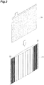
- Figure 3 is a view showing a sack-shaped separator 20, and an electrode (for example, negative electrode) 14 accommodated in the separator 20.
- the separator 10 which is used in the production of the separator 20 is formed, for example, in the shape of an elongated sheet.
- the separator 20 shown in Figure 3 is obtained by cutting the separator 10 to an appropriate length; folding the separator into two in the longitudinal direction of the separator 10; arranging the electrode 14 in the inside; overlapping the separator 10; and mechanically sealing, crimping or thermally bonding both of the side portions (for example, reference numeral 22 in Figure 3 indicates mechanically sealed portion).
- the lead acid storage battery of the present embodiment may have a nonwoven fabric between the positive electrode and the negative electrode.
- the separator is further excellent in suppressing effect on the liquid reduction of the electrolytic solution.
- the factor for the further excellent suppressing effect on the liquid reduction of the electrolytic solution is unclear, but it is inferred as follows.
- the nonwoven fabric may be arranged between the negative electrode and the separator, or may be arranged between the positive electrode and the separator. By arranging the nonwoven fabric between the negative electrode and the separator, it is possible to further suppress the stratification.
- the nonwoven fabric is preferably arranged so as to come in contact with an electrode (negative electrode or positive electrode).
- the nonwoven fabric may be arranged inside a sack-shaped separator.
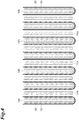
- Figure 4 is a cross-sectional view showing one example of a layered structure of the electrodes, the separators, and the nonwoven fabrics.
- one electrode 14a and the other electrode 14b out of the positive electrode and the negative electrode are alternately layered via the separator 10 and the nonwoven fabric 30.
- the nonwoven fabric 30 and the electrode 14b can be accommodated in the sack-shaped separator 10 by overlapping the separator 10 and the nonwoven fabric 30 to obtain an elongated layered sheet; and then arranging the electrode 14b in the space formed by bending the layered sheet in the longitudinal direction thereof at the middle of the longitudinal direction; and bonding the sheets on ends of both sides to each other, which are adjacent to the bent portion.
- the electrode 14b is, for example, the negative electrode.
- the constituent material of the nonwoven fabric is not limited in particular as long as the constituent material is resistant to the electrolytic solution.
- Specific examples of the constituent material of the nonwoven fabric include an organic fiber, an inorganic fiber, pulp and inorganic oxide powder.
- the organic fiber include polyolefin fibers (polyethylene fiber, polypropylene fiber or the like), and polyethylene terephthalate fiber.
- the inorganic fiber include a glass fiber and the like.
- the nonwoven fabric preferably contains at least one selected from the group consisting of an organic fiber, a glass fiber and pulp, in view of the further excellent stratification-suppressing effect.
- a mixed fiber containing an inorganic fiber and pulp may be used, and an organic/inorganic mixed fiber containing an organic fiber and an inorganic fiber may also be used.
- the thickness of the nonwoven fabric is preferably 0.03 mm or more, and more preferably 0.1 mm or more, in view of the further excellent stratification-suppressing effect and in view of improving the strength of the nonwoven fabric.
- the thickness of the nonwoven fabric is preferably 0.4 mm or less, and more preferably 0.3 mm or less, in view of easily suppressing an increase in internal resistance.
- the nonwoven fabric may not be used. In this case, it is suppressed that diffusion of a sulfate ion is shielded by the nonwoven fabric, and accordingly it tends to easily obtain excellent charge acceptability.
- the electrolytic solution of the lead acid storage battery of the present embodiment contains an aluminum ion.
- the electrolytic solution containing the aluminum ion it is possible to obtain the excellent short circuit-suppressing effect even when the separator containing silica is used.
- the electrolytic solution containing the aluminum ion due to the electrolytic solution containing the aluminum ion, it is possible to obtain the excellent suppressing effect on the liquid reduction of the electrolytic solution.
- the positive electrode side tends to form an alkaline atmosphere when the discharge reaction occurs, and in the case where an aluminum ion does not exist in the electrolytic solution, the silica becomes easy to dissolve when it becomes alkaline. It is inferred that, if the silica dissolves, the separator shrinks to decrease the thickness of the separator, and consequently the short circuit tends to easily occur.
- the electrolytic solution contains an aluminum ion, and thereby an aluminum compound such as aluminum hydroxide precipitates inside the separator at the time of discharge.
- the aluminum compound such as aluminum hydroxide precipitates, and thereby the dissolution of silica is suppressed, which consequently can keep the thickness of the separator.
- the precipitation reaction of the aluminum compound such as the aluminum hydroxide can alleviate an increase in the pH of the electrolytic solution (shift of pH to alkaline side), and accordingly the increase in the solubility of the lead sulfate can be suppressed. It is inferred that for these reasons, the existence of the aluminum ion in the electrolytic solution can suppress the short circuit.
- the electrolytic solution does not contain an aluminum ion
- the electrolytic solution contains an aluminum ion
- not only a hydrogen ion but also an aluminum ion move to the vicinity of the negative electrode during charging. Due to the influence of this aluminum ion, the number of a hydrogen ion existing in the vicinity of the negative electrode decreases, accordingly the reaction potential falls, and the hydrogen generation overpotential increases. It is inferred that for this reason, the existence of an aluminum ion in the electrolytic solution can suppress the liquid reduction of the electrolytic solution.
- the aluminum ion concentration of the electrolytic solution is preferably 0.01 mol/L or more, more preferably 0.02 mol/L or more, and further preferably 0.05 mol/L or more, based on the total amount of the electrolytic solution, in view of the further excellent short circuit-suppressing effect and the further excellent suppressing effect on the liquid reduction of the electrolytic solution, and in view of further improving the battery characteristics such as the charge acceptability.
- the aluminum ion concentration of the electrolytic solution may be 0.08 mol/L or more, 0.1 mol/L or more, 0.12 mol/L or more, 0.14 mol/L or more, and 0.15 mol/L or more.
- the aluminum ion concentration of the electrolytic solution is preferably 0.3 mol/L or less, more preferably 0.25 mol/L or less, and further preferably 0.2 mol/L or less, based on the total amount of the electrolytic solution, in view of the further excellent short circuit-suppressing effect and the further excellent suppressing effect on the liquid reduction of the electrolytic solution, and in view of further improving the charge acceptability and the cycle characteristics.
- the aluminum ion concentration of the electrolytic solution is preferably 0.01 to 0.3 mol/L, more preferably 0.02 to 0.25 mol/L, and further preferably 0.05 to 0.2 mol/L, based on the total amount of the electrolytic solution.
- the aluminum ion concentration of the electrolytic solution may be 0.08 to 0.2 mol/L, may be 0.1 to 0.2 mol/L, may be 0.12 to 0.2 mol/L, may be 0.14 to 0.2 mol/L and may be 0.15 to 0.2 mol/L.
- the aluminum ion concentration of the electrolytic solution can be measured, for example, by ICP emission spectroscopy (high frequency induction coupled plasma emission spectroscopy).
- a solubility of the crystalline lead sulfate, which is a discharge product, into the electrolytic solution increases, or a diffusibility of the electrolytic solution into the electrode active material improves due to a high ion conductivity of the aluminum ion, under arbitrary low SOC, and accordingly that the charge acceptability improves.
- the electrolytic solution contains, for example, an aluminum ion and sulfuric acid.
- the electrolytic solution may further contain an ion other than the aluminum ion (sodium ion, potassium ion, phosphate ion or the like).
- the electrolytic solution preferably contains a sodium ion, in view of the further excellent suppressing effect on the liquid reduction of the electrolytic solution.
- the sodium ion concentration of the electrolytic solution is preferably 0.04 mol/L or more, more preferably 0.05 mol/L or more, further preferably more than 0.05 mol/L, particularly preferably 0.055 mol/L or more, and extremely preferably 0.06 mol/L or more, based on the total amount of the electrolytic solution, in view of the further excellent suppressing effect on the liquid reduction of the electrolytic solution.
- the sodium ion concentration of the electrolytic solution is preferably 1.00 mol/L or less, more preferably 0.09 mol/L or less, further preferably 0.08 mol/L or less, and particularly preferably 0.07 mol/L or less, based on the total amount of the electrolytic solution, in view of the further excellent suppressing effect on the liquid reduction of the electrolytic solution.
- the sodium ion concentration of the electrolytic solution is preferably 0.04 to 1.00 mol/L, more preferably 0.05 to 0.09 mol/L, further preferably more than 0.05 to 0.08 mol/L or less, particularly preferably 0.055 to 0.07 mol/L, and extremely preferably 0.06 to 0.07 mol/L, based on the total amount of the electrolytic solution.
- the sodium ion concentration of the electrolytic solution can be measured, for example, by ICP emission spectroscopy (high frequency induction coupled plasma emission spectroscopy).
- the positive electrode material contains a positive electrode active material.
- the positive electrode active material can be obtained by aging and drying a positive electrode material paste containing a raw material of the positive electrode active material to obtain an unformed positive electrode active material; and then forming the unformed positive electrode active material.
- the positive electrode active material after the formation preferably contains ⁇ -lead dioxide ( ⁇ -PbO 2 ), and also may further contain ⁇ -lead dioxide ( ⁇ -PbO 2 ).
- the raw material of the positive electrode active material is not limited in particular, and examples include lead powder.
- the lead powder examples include lead powder (for example, mixture of main component PbO powder and scaly metallic lead, in ball mill type lead powder producing machine) which is produced, for example, by a ball mill type lead powder producing machine or a Burton-pot type lead powder producing machine.
- Red lead (Pb 3 O 4 ) may be used as the raw material of the positive electrode active material.
- the unformed positive electrode material preferably contains an unformed positive electrode active material containing a tribasic lead sulfate, as a main component.
- the average particle size of the positive electrode active material is preferably 0.3 ⁇ m or more, more preferably 0.5 ⁇ m or more, and further preferably 0.7 ⁇ m or more, in view of further improving the charge acceptability and the cycle characteristics.
- the average particle size of the positive electrode active material is preferably 2.5 ⁇ m or less, more preferably 2 ⁇ m or less, and further preferably 1.5 ⁇ m or less, in view of further improving the cycle characteristics.
- the above described average particle size of the positive electrode active material is an average particle size of a positive electrode active material in a positive electrode material after the formation.
- the average particle size of the positive electrode active material can be obtained as a numerical value which is obtained by arithmetically averaging the values of long-side lengths (maximum particle sizes) of all the active material particles in a range of 10 ⁇ m in length ⁇ 10 ⁇ m in width, in an image of a scanning electron microscopic photograph (1000 magnifications) for the positive electrode material in the central portion of the positive electrode after the formation.
- the content of the positive electrode active material is preferably 95 mass% or more, more preferably 97 mass% or more, and further preferably 99 mass% or more, based on the total mass of the positive electrode material, in view of the further excellent battery characteristics (capacity, low-temperature high-rate discharge performance, charge acceptability, cycle characteristics and the like).
- the upper limit of the content of the positive electrode active material may be 100 mass% or less.
- the above described content of the positive electrode active material is a content of the positive electrode active material in the positive electrode material after the formation.
- the positive electrode material may further contain an additive.
- the additive include a carbon material (carbonaceous conductive material. Carbon fiber is excluded), and short fiber for reinforcement.
- the carbon material include carbon black and graphite.
- the carbon black include furnace black (Ketchen black and the like), channel black, acetylene black and thermal black.
- the short fiber for reinforcement include acrylic fiber, polyethylene fiber, polypropylene fiber, polyethylene terephthalate fiber and carbon fiber.
- the lower limit of the specific surface area of the positive electrode material is preferably 3 m 2 /g or more, more preferably 4 m 2 /g or more, and further preferably 5 m 2 /g or more, in view of the further excellent charge acceptability.
- the upper limit of the specific surface area of the positive electrode material is not limited in particular, but is preferably 15 m 2 /g or less, more preferably 13 m 2 /g or less, and further preferably 12 m 2 /g or less, in view of practical use and in view of making the utilization rate excellent.
- the above described specific surface area of the positive electrode material is a specific surface area of the positive electrode material after the formation.
- the specific surface area of the positive electrode material can be adjusted, for example, by a method of adjusting amounts of sulfuric acid and water added when the positive electrode material paste is produced, a method of refining the active material at a stage where the positive electrode active material is unformed, a method of changing a formation condition, and the like.
- the specific surface area of the positive electrode material can be measured, for example, by a BET method.
- the BET method is a method of making the surface of a measurement sample adsorb an inert gas of which one molecule size is known (for example, nitrogen gas), and determining the surface area from the amount adsorbed and the occupying area of the inert gas; and is a general measurement method of the specific surface area. Specifically, the measurement is performed on the basis of the following BET equation.
- the following expression (2) is obtained by modifying the expression (1) (dividing numerator and denominator on left side by P).
- the specific surface area meter that is used for the measurement makes a gas molecule of which the adsorption occupying area is known adsorbed onto the sample and measures a relation between the amount adsorbed (V) and the relative pressure (P/P o ).
- V amount adsorbed
- P/P o relative pressure
- the left side of the expression (2) and P/Po are plotted.
- the following expression (3) is derived from the expression (2).
- the intercept i the intercept i and the gradient s are given by the following expressions (4) and (5), respectively.
- the total surface area S total (m 2 ) of the sample is determined by the following expression (9), and the specific surface area S (m 2 /g) is determined by the following expression (10) on the basis of the total surface area S total .
- N represents an Avogadro's number
- a CS represents an adsorption cross-sectional area (m 2 )
- M represents a molecular weight.
- w represents the quantity (g) of the sample.
- the porosity of the positive electrode material is preferably 50% by volume or more, and more preferably 55% by volume or more, from the viewpoint of increasing a region in which sulfuric acid enters a pore portion (pore) in the positive electrode material to easily increase the capacity.
- the upper limit of the porosity of the positive electrode material is not limited in particular, but is preferably 70% by volume or less, from the viewpoint that the amount in which the pore portion in the positive electrode material is impregnated with sulfuric acid is adequate, and a bonding force between the active materials can be adequately kept.
- the upper limit of the porosity is more preferably 60% by volume or less, in view of practical use.
- the above described porosity of the positive electrode material is a porosity of the positive electrode material after the formation.
- the porosity of the positive electrode material is, for example, a value (percentage based on volume) which is obtained from mercury porosimeter measurement.
- the porosity of the positive electrode material can be adjusted, for example, by the amount of dilute sulfuric acid added when the positive electrode material paste is prepared.
- the negative electrode material contains a negative electrode active material.
- the negative electrode active material can be obtained by aging and drying a negative electrode material paste containing a raw material of the negative electrode active material to obtain an unformed negative electrode active material; and then forming the unformed negative electrode active material.
- Examples of the negative electrode active materials after the formation include spongy lead.
- the above described spongy lead tends to react with sulfuric acid in the electrolytic solution and gradually turn into lead sulfate (PbSO 4 ).
- the raw materials of the negative electrode active material include lead powder.
- the lead powder examples include lead powder (for example, mixture of main component PbO powder and scaly metallic lead, in ball mill type lead powder producing machine) which is produced, for example, by a ball mill type lead powder producing machine or a Burton-pot type lead powder producing machine.
- the unformed negative electrode active material is composed of, for example, basic lead sulfate, metal lead and a low-grade oxide.
- the average particle size of the negative electrode active material is preferably 0.3 ⁇ m or more, more preferably 0.5 ⁇ m or more, and further preferably 0.7 ⁇ m or more, in view of further improving the charge acceptability and the cycle characteristics.
- the average particle size of the negative electrode active material is preferably 2.5 ⁇ m or less, more preferably 2 ⁇ m or less, and further preferably 1.5 ⁇ m or less, in view of further improving the cycle characteristics.
- the above described average particle size of the negative electrode active material is an average particle size of the negative electrode active material in the negative electrode material after the formation.
- the average particle size of the negative electrode active material can be obtained as a numerical value which is obtained by arithmetically averaging the values of long-side lengths (maximum particle size) of all the active material particles in a range of 10 ⁇ m in length ⁇ 10 ⁇ m in width, in an image of a scanning electron microscopic photograph (1000 magnifications) for the negative electrode material in the central portion of the negative electrode after the formation.
- the content of the negative electrode active material is preferably 93 mass% or more, more preferably 95 mass% or more, and further preferably 98 mass% or more, based on the total mass of the negative electrode material, in view of making the battery characteristics (capacity, low-temperature high-rate discharge performance, charge acceptability, cycle characteristics and the like) further better.
- the upper limit of the content of the negative electrode active material may be 100 mass% or less.
- the above described content of the negative electrode active material is a content of a negative electrode active material in the negative electrode material after the formation.
- the negative electrode material may further contain an additive.
- additives include: a resin (resin having sulfone group and/or sulfonate group) which has at least one selected from the group consisting of a sulfone group (sulfonic acid group; sulfo group) and a sulfonate group (for example, a group formed by replacing hydrogen atom of sulfone group with alkali metal); barium sulfate; a carbon material (carbonaceous conductive material. Carbon fiber is excluded); and short fiber for reinforcement.
- the negative electrode material contains the resin having at least one selected from the group consisting of the sulfone group and the sulfonate group, and thereby it is possible to further improve the charge acceptability.
- the resins having the sulfone group and/or sulfonate group include: a bisphenol-based resin having a sulfone group and/or a sulfonate group (hereinafter simply referred to as "bisphenol-based resin"); lignin sulfonic acid; and a lignin sulfonate.
- the lignin sulfonic acid is a compound in which a part of decomposed products of lignin is sulfonated.
- the lignin sulfonates include potassium lignin sulfonate and sodium lignin sulfonate.
- the bisphenol-based resin is preferable, in view of further improving the charge acceptability.
- the bisphenol-based resin is preferably a resin obtained by a reaction of: a bisphenol-based compound; at least one selected from the group consisting of aminoalkylsulfonic acid, an aminoalkylsulfonic acid derivative, aminoarylsulfonic acid and an aminoarylsulfonic acid derivative; and at least one selected from the group consisting of formaldehyde and a formaldehyde derivative.
- the bisphenol-based compound is a compound having two hydroxyphenyl groups.
- examples of the bisphenol-based compound include 2,2-bis(4-hydroxyphenyl)propane (also referred to as "bisphenol A”), bis(4-hydroxyphenyl)methane, 1,1-bis(4-hydroxyphenyl)ethane, 2,2-bis(4-hydroxyphenyl)hexanuoropropane, 1,1-bis(4-hydroxyphenyl)-1-phenylethane, 2,2-bis(4-hydroxyphenyl)butane, bis(4-hydroxyphenyl)diphenylmethane, 1,1-bis(4-hydroxyphenyl)cyclohexane, 1,1-bis(4-hydroxyphenyl)-3,3,5-trimethylcyclohexane, and bis(4-hydroxyphenyl)sulfone (also referred to as "bisphenol S").
- bisphenol S bis(4-hydroxyphenyl)sulfone
- aminoalkylsulfonic acid examples include aminomethanesulfonic acid, 2-aminoethanesulfonic acid, 3-aminopropanesulfonic acid, and 2-methylaminoethanesulfonic acid.
- aminoalkylsulfonic acid derivative examples include a compound formed by replacing a hydrogen atom of the aminoalkylsulfonic acid with an alkyl group (for example, alkyl group having 1 to 5 carbon atoms) or the like, and an alkali metal salt formed by replacing a hydrogen atom of a sulfonic group (-SO 3 H) of the aminoalkylsulfonic acid with an alkali metal (for example, sodium or potassium).
- aminoarylsulfonic acid examples include aminobenzenesulfonic acid (4-aminobenzenesulfonic acid and the like), and aminonaphthalenesulfonic acid.
- aminoarylsulfonic acid derivative examples include a compound formed by replacing a hydrogen atom of aminoarylsulfonic acid with an alkyl group (for example, alkyl group having 1 to 5 carbon atoms) or the like, and an alkali metal salt formed by replacing a hydrogen atom of a sulfone group (-SO 3 H) of the aminoarylsulfonic acid with an alkali metal (for example, sodium or potassium).
- formaldehyde derivative examples include paraformaldehyde, hexamethylenetetramine, and trioxane.
- the bisphenol-based resin preferably has at least one selected from the group consisting of a structural unit represented by the following formula (I) and a structural unit represented by the following formula (II).
- X 1 represents a divalent group; A 1 represents an alkylene group having 1 to 4 carbon atoms or an arylene group; R 11 represents an alkali metal or a hydrogen atom; R 12 represents a methylol group (-CH 2 OH); R 13 and R 14 each independently represents an alkali metal or a hydrogen atom; n11 represents an integer of 1 to 600; n12 represents an integer of 1 to 3; and n13 represents 0 or 1.]
- X 2 represents a divalent group; A 2 represents an alkylene group having 1 to 4 carbon atoms or an arylene group; R 21 represents an alkali metal or a hydrogen atom; R 22 represents a methylol group (-CH 2 OH); R 23 and R 24 each independently represents an alkali metal
- a ratio between the structural unit represented by the formula (I) and the structural unit represented by the formula (II) is not limited in particular, and can vary depending on the synthetic condition or the like.
- a resin that has only either one of the structural unit represented by the formula (I) and the structural unit represented by the formula (II) may be used for the bisphenol-based resin.
- Examples of the X 1 and X 2 include an organic group such as an alkylidene group (methylidene group, ethylidene group, isopropylidene group, sec-butylidene group and the like), a cycloalkylidene group (cyclohexylidene group and the like), and a phenylalkylidene group (diphenylmethylidene group, phenylethylidene group and the like); and a sulfonyl group: and isopropylidene group (-C(CH 3 ) 2 -) is preferred in view of the further excellent charge acceptability, and sulfonyl group (-SO 2 -) is preferred in view of the further excellent discharge characteristics.
- an alkylidene group methylidene group, ethylidene group, isopropylidene group, sec-butylidene group and the like
- a cycloalkylidene group
- the X 1 and X 2 may be substituted with a halogen atom such as a fluorine atom.
- a halogen atom such as a fluorine atom.
- the hydrocarbon ring may be substituted with an alkyl group or the like.
- Examples of the A 1 and A 2 include an alkylene group having 1 to 4 carbon atoms such as a methylene group, an ethylene group, a propylene group and a butylene group; and a divalent arylene group such as a phenylene group and a naphthylene group.
- the above described arylene group may be substituted with an alkyl group or the like.
- alkali metals of R 11 , R 13 , R 14 , R 21 , R 23 and R 24 include sodium and potassium.
- n11 and n21 are preferably 5 to 300 in view of the further excellent cycle characteristics and the further excellent solubility in the solvent.
- n12 and n22 are preferably 1 or 2, and more preferably 1, in view of improving the charge acceptability, the discharge characteristics and the cycle characteristics in a well-balanced manner.
- n13 and n23 are preferably 0, though the values vary depending on the production conditions, in view of the further excellent cycle characteristics and the excellent storage stability of the bisphenol-based resin.
- the weight average molecular weight of the resin (bisphenol-based resin and the like) having the sulfone group and/or the sulfonate group is preferably 3000 or more, more preferably 10000 or more, further preferably 20000 or more, and particularly preferably 30000 or more, in view of suppressing the elution of the resin having the sulfone group and/or the sulfonate group from the electrode to the electrolytic solution in the lead acid storage battery to thereby easily improve the cycle characteristics.
- the weight average molecular weight of the resin having the sulfone group and/or the sulfonate group is preferably 200000 or less, more preferably 150000 or less, and further preferably 100000 or less, in view of suppressing the lowering of adsorptivity to an electrode active material and the lowering of dispersibility to thereby easily improve the cycle characteristics.
- the weight average molecular weight of the resin having the sulfone group and/or the sulfonate group can be measured, for example, by gel permeation chromatography (hereinafter referred to as "GPC") on the following conditions. (GPC condition)
- the content of the resin having the sulfone group and/or the sulfonate group is preferably 0.01 mass% or more, more preferably 0.05 mass% or more, and further preferably 0.1 mass% or more in terms of a solid content of the resin, based on the total mass of the negative electrode material, in view of obtaining the further excellent charge acceptability.
- the content of the resin having the sulfone group and/or the sulfonate group is preferably 2 mass% or less, more preferably 1 mass% or less, and further preferably 0.3 mass% or less in terms of a solid content of the resin, based on the total mass of the negative electrode material, in view of obtaining the further excellent discharge characteristics.
- Examples of the carbon material include carbon black and graphite.
- Examples of the carbon black include furnace black (Ketchen black and the like), channel black, acetylene black and thermal black.
- Examples of the short fiber for reinforcement include acrylic fiber, polyethylene fiber, polypropylene fiber, polyethylene terephthalate fiber and carbon fiber.
- the specific surface area of the negative electrode material is preferably 0.4 m 2 /g or more, more preferably 0.5 m 2 /g or more, and further preferably 0.6 m 2 /g or more, in view of enhancing the reactivity of the electrolytic solution with the negative electrode active material.
- the specific surface area of the negative electrode material is preferably 2 m 2 /g or less, more preferably 1.8 m 2 /g or less, and further preferably 1.5 m 2 /g or less, in view of further suppressing the shrinkage of the negative electrode during the cycle.
- the above described specific surface area of the negative electrode material is the specific surface area of the negative electrode material after the formation.
- the specific surface area of the negative electrode material can be adjusted, for example, by a method of adjusting the amounts of sulfuric acid and water added when the negative electrode material paste is prepared, a method of refining the active material at a stage where the negative electrode active material is unformed, and a method of changing a formation condition.
- the specific surface area of the negative electrode material can be measured, for example, by the BET method.
- Examples of the method for producing the current collector include a casting method, an expanding method and a stamping method.
- Examples of the material of the current collector include a lead-calcium-tin-based alloy and a lead-antimony-based alloy. A small amount of selenium, silver, bismuth or the like can be added thereto.
- the current collector can be obtained, for example, by forming these materials into a grid shape or a mesh shape according to the previously described production method.
- the material and/or production methods of the current collectors of the positive electrode and the negative electrode may be identical to or different from each other.
- the production method for the lead acid storage battery of the present embodiment comprises, for example, an electrode production step of obtaining the electrodes (positive electrode and negative electrode); and an assembling step of assembling constituent members including the above described electrodes to obtain the lead acid storage battery.
- an unformed electrode is obtained by: filling the current collector (cast grid body obtained according to casting method, expanded grid body obtained according to expanding method, or the like) with an electrode material paste (positive electrode material paste and negative electrode material paste); and then performing the aging and drying.
- the positive electrode material paste contains, for example, a raw material (lead powder and the like) of the positive electrode active material, and may further contain another additive.
- the negative electrode material paste contains a raw material (lead powder and the like) of the negative electrode active material; the paste preferably contains a resin (bisphenol-based resin and the like) having a sulfone group and/or a sulfonate group, as a dispersion agent; and the paste may further contain another additive.
- the positive electrode material paste for obtaining the positive electrode material can be obtained, for example, according to the following method.
- red lead (Pb 3 O 4 ) may be used as the raw material of the positive electrode active material, in view of enabling a reduction of the formation time.
- the additive short fiber for reinforcement and the like
- the dry-mixing is performed to obtain a mixture.
- the positive electrode material paste is obtained by adding sulfuric acid (dilute sulfuric acid and the like) and a solvent (water such as ion-exchanged water, organic solvent, or the like) to this mixture; and performing the kneading.
- the unformed positive electrode can be obtained by filling the current collector with the positive electrode material paste; and then performing the aging and drying.
- the amount of the short fiber for reinforcement blended is preferably 0.005 to 0.3 mass%, and more preferably 0.05 to 0.3 mass%, based on the total mass of the raw material (lead powder and the like) of the positive electrode active material.
- the aging conditions for obtaining the unformed positive electrode are preferably 15 to 60 hours in an atmosphere at a temperature of 35 to 85°C and a relative humidity of 50 to 98% RH.
- the drying conditions are preferably 15 to 30 hours at a temperature of 45 to 80°C.
- the negative electrode material paste can be obtained, for example, according to the following method. Firstly, a mixture is obtained by adding additives (resin having sulfone group and/or sulfonate group, carbon material, short fiber for reinforcement, barium sulfate, and the like) to the raw material of the negative electrode active material; and performing the dry-mixing. Then, the negative electrode material paste is obtained by adding sulfuric acid (dilute sulfuric acid or the like) and a solvent (water such as ion-exchanged water, organic solvent, or the like) to this mixture; and performing the kneading. The unformed negative electrode can be obtained by filling the current collector with this negative electrode material paste; and then performing the aging and drying.
- additives resin having sulfone group and/or sulfonate group, carbon material, short fiber for reinforcement, barium sulfate, and the like
- the amount of each component blended is preferably in the following range.
- the amount of the resin having the sulfone group and/or the sulfonate group blended is preferably 0.01 to 2.0 mass%, more preferably 0.05 to 1.0 mass%, further preferably 0.1 to 0.5 mass%, and particularly preferably 0.1 to 0.3 mass% in terms of the solid content of the resin, based on the total mass of the raw material (lead powder and the like) of the negative electrode active material.
- the amount of the carbon material blended is preferably 0.1 to 3 mass%, and more preferably 0.2 to 1.4 mass%, based on the total mass of the raw material (lead powder and the like) of the negative electrode active material.
- the amount of the short fiber for reinforcement blended is preferably 0.05 to 0.3 mass%, based on the total mass of the raw material (lead powder and the like) of the negative electrode active material.
- the amount of barium sulfate blended is preferably 0.01 to 2.0 mass%, and more preferably 0.01 to 1.0 mass%, based on the total mass of the raw material (lead powder and the like) of the negative electrode active material.
- the aging conditions for obtaining the unformed negative electrode are preferably 15 to 30 hours in an atmosphere at a temperature of 45 to 65°C and a relative humidity of 70 to 98% RH.
- the drying conditions are preferably 15 to 30 hours at a temperature of 45 to 60°C.
- the unformed negative electrode and the unformed positive electrode that have been produced as described above are alternately layered via a separator, and current collecting portions of the electrodes that have the same polarity are connected (welded or the like) to each other with a strap, to thereby obtain a group of electrodes.
- This group of electrodes is arranged in a battery case to produce an unformed battery.
- the electrolytic solution is poured into the unformed battery, and then a direct current is passed to perform the formation in the battery case.
- the lead acid storage battery is obtained by adjusting the specific gravity of the electrolytic solution after the formation, to an appropriate specific gravity.
- the above described electrolytic solution contains, for example, sulfuric acid and an aluminum ion, and can be obtained by mixing sulfuric acid and aluminum sulfate powder.
- the aluminum sulfate dissolved in the electrolytic solution can be added as an anhydride or a hydrate.
- a specific gravity of the electrolytic solution (electrolytic solution containing an aluminum ion) after the formation is preferably in the following range.
- the specific gravity of the electrolytic solution is preferably 1.25 or more, more preferably 1.26 or more, further preferably 1.27 or more, and particularly preferably 1.275 or more, in view of further suppressing a penetration short circuit or freeze and also in view of the further excellent discharge characteristics.
- the specific gravity of the electrolytic solution is preferably 1.33 or less, more preferably 1.32 or less, further preferably 1.31 or less, and particularly preferably 1.30 or less, in view of further improving the charge acceptability and the cycle characteristics.
- the value of the specific gravity of the electrolytic solution can be measured, for example, with a floating type specific gravity meter or a digital specific gravity meter made by Kyoto Electronics Manufacturing Co., Ltd.
- the battery case is a member which can accommodate electrodes (polar plates and the like) in its inside.
- the battery case is preferably a member that has a box body of which the upper face is opened and has a lid body which covers the upper face of the box body, in view of easily accommodating the electrode therein.
- An adhesive, thermal welding, laser welding, ultrasonic welding and the like can be appropriately used in bonding of the box body to the lid body.
- the shape of the battery case is not limited in particular, but a rectangular shape is preferable so that the ineffective space becomes small when the electrode (polar plate that is plate-shaped body, and the like) is accommodated.
- the material of the battery case is not limited in particular, but needs to be resistant to the electrolytic solution (dilute sulfuric acid and the like).
- Specific examples of the material of the battery case include PP (polypropylene), PE (polyethylene) and an ABS resin.
- PP polypropylene
- PE polyethylene
- ABS resin an ABS resin.
- the material is PP, it is advantageous in terms of acid resistance, workability and economical efficiency.
- the PP is advantageous in terms of the workability, as compared with the ABS resin in which case heat welding between the battery case and the lid is difficult.
- the materials of the box body and the lid body may be identical materials to each other, or may be different materials from each other.
- the materials of the box body and the lid body are preferably a material having the same coefficient of thermal expansion, from the viewpoint that a too large stress does not occur.
- the condition of the formation and the specific gravity of the sulfuric acid can be adjusted according to the properties of the electrode active material.
- the formation treatment is not limited to being performed after the assembling step, but may be performed after aging and drying in the electrode production step (tank formation).
- the raw materials of the positive electrode active material, 0.07 mass% of the short fiber for reinforcement (acrylic fiber) based on the total mass of the raw materials of the positive electrode active material, and water were mixed and kneaded. Subsequently, the kneading was performed while dilute sulfuric acid (specific gravity of 1.280) was added little by little, to produce a positive electrode material paste.
- An expanded grid body which was produced by subjecting a rolled sheet consisting of a lead alloy to expand working was filled with the positive electrode material paste. Subsequently, the grid body (current collector) which was filled with the positive electrode material paste was aged in an atmosphere of a temperature of 50°C and a humidity of 98% for 24 hours. After that, the drying was performed to produce an unformed positive electrode plate.
- Lead powder was used as a raw material of the negative electrode active material.
- a mixture was added to the above described lead powder wherein the mixture contained 0.2 mass% (in terms of solid content) of Bisperse P215 (condensate of bisphenol-based compound, aminobenzenesulfonic acid and formaldehyde, trade name, and made by Nippon Paper Industries Co., Ltd.), 0.1 mass% of a short fiber for reinforcement (acrylic fiber), 1.0 mass% of barium sulfate, and 0.2 mass% of carbonaceous material (furnace black); and then the dry-mixing was performed (where the above described amount blended is an amount blended based on the total mass of the raw material of the negative electrode active material).
- Bisperse P215 condensate of bisphenol-based compound, aminobenzenesulfonic acid and formaldehyde, trade name, and made by Nippon Paper Industries Co., Ltd.
- 0.1 mass% of a short fiber for reinforcement acrylic fiber
- a sack-shaped separator was prepared by processing the elongated sheet-like article, which contained polyethylene and silica particles and had a plurality of linear ribs and mini ribs arranged on one surface, into a sack shape so that the surface having the ribs and the mini ribs arranged thereon was positioned to the outside (see Figure 1 and Figure 3 ).
- Each of the ribs and the mini ribs is arranged in such a way as to be approximately parallel to each other, and extends in the longitudinal direction of the separator. In the transverse direction of the separator, the first regions each containing the rib are positioned between the two second regions containing the mini ribs. The details of the separator are shown below.
- the unformed negative electrode plate was accommodated in the above described sack-shaped separator.
- five unformed positive electrode plates, and six unformed negative electrode plates which were accommodated in the above described sack-shaped separator were alternately layered such that the ribs of the separator came in contact with the positive electrode plate.
- ear portions of the polar plates having the same polarity were welded to each other by a cast-on strap (COS) method to produce a polar plate group.
- COS cast-on strap
- the dilute sulfuric acid (electrolytic solution) having a specific gravity of 1.23 in which aluminum sulfate anhydride was dissolved so that the aluminum ion concentration became 0.08 mol/L was poured into this battery. After that, the formation was performed at a passing current of 10A for 16 hours in a water bath at 50°C, the specific gravity of the electrolytic solution after the formation was adjusted to 1.280, to obtain the lead acid storage battery.
- the separator at the time before the battery was assembled was cut by an ion-milling apparatus E-3500 (trade name, made by Hitachi High-Technologies Corporation), to expose the cross section of the separator.
- the cross section of the separator was subjected to an EDX analysis by using a scanning electron microscope (trade name: JSM-6010LA, made by JEOL Ltd.). Mapping analysis was carried out at a magnification of 300 times; after the measurement, a separator portion was selected, and amounts of existence of carbon, oxygen and silicon were quantified; and the amounts were converted into the masses of the respective elements.
- the total amount (mass%) of the masses of oxygen and silicon in the separator was calculated based on the total mass of the obtained carbon, oxygen and silicon.
- the conditions of the mapping analysis were set such that the acceleration voltage was 15 kV, the spot size was 72, the pressure in the low vacuum mode was 35 Pa, the dwell time was 1 millisecond, the process time was T4, the number of pixels was 512 ⁇ 384, and the number of integration was 5 times.
- a result of the quantitative analysis for each of the elements is shown in Table 1.
- a measurement sample for the specific surface area was produced according to the following procedure. Firstly, the formed battery was disassembled; the electrode plates (positive electrode plate and negative electrode plate) were taken out and were washed with water; and then were dried at 50°C for 24 hours. Next, 2 g of each of the electrode materials (positive electrode material and negative electrode material) was collected from the central portion of the above described electrode plate, and was dried at 130°C for 30 minutes to produce the measurement samples.
- the amount of nitrogen gas adsorbed was measured at a liquid nitrogen temperature according to a multipoint method while the measurement sample which was produced in the above description was cooled with liquid nitrogen, and the specific surface areas of the positive electrode material and the negative electrode material after the formation were calculated according to the BET method.
- the measurement conditions were as shown below. As a result of having measured in this way, the specific surface area of the positive electrode material was 5 m 2 /g and the specific surface area of the negative electrode material was 0.6 m 2 /g.
- Lead acid storage batteries were produced in a similar method to that in Example 1, except that the dilute sulfuric acids having a specific gravity of 1.280 (after formation) were used as the electrolytic solution, wherein the dilute sulfuric acids were prepared so that the aluminum ion concentrations became values shown in Table 1.
- a lead acid storage battery was produced in a similar method to that in Example 1, except that the dilute sulfuric acid having a specific gravity of 1.280 (after formation) was used as the electrolytic solution, wherein the dilute sulfuric acid was obtained by dissolving aluminum sulfate anhydride and sodium sulfate so that the aluminum ion concentration became 0.14 mol/L and the sodium ion concentration became 0.06 mol/L.
- Lead acid storage batteries of Examples 5 to 8 were produced in similar methods to those in Examples 1 to 4, except that a nonwoven fabric (nonwoven fabric consisting of glass fiber with thickness of 0.3 mm) was arranged between the negative electrode plate and the separator. Specifically, the above described elongated sheet-like article (sheet-like article containing polyethylene and silica particle) and the nonwoven fabric were overlapped, then was worked into a sack shape so that the nonwoven fabric was positioned in the inside, to produce the sack-shaped separator. After that, the unformed negative electrode plate was accommodated in the above described sack-shaped separator so that the nonwoven fabric came in contact with both surfaces of the negative electrode plate.
- a nonwoven fabric nonwoven fabric consisting of glass fiber with thickness of 0.3 mm
- a lead acid storage battery was produced in a similar method to that in Example 1, except that the dilute sulfuric acid having a specific gravity of 1.280 (after formation) was used as the electrolytic solution, wherein the dilute sulfuric acid did not contain the aluminum ion.
- a lead acid storage battery was produced in a similar method to that in Example 1, except that the dilute sulfuric acid having a specific gravity of 1.280 (after formation) was used as the electrolytic solution, wherein the dilute sulfuric acid was obtained by dissolving sodium sulfate so that the sodium ion concentration became 0.1 mol/L.
- a lead acid storage battery was produced in a similar method to that in Example 5, except that the dilute sulfuric acid having a specific gravity of 1.280 (after formation) was used as the electrolytic solution, wherein the dilute sulfuric acid did not contain the aluminum ion.
- the produced lead acid storage battery was discharged at a constant current of 5.6 A for 30 minutes at an ambient temperature of 25°C, and was left for 6 hours. After that, the lead acid storage battery was charged at a constant voltage of 2.33 V under a limited current of 100 A for 60 seconds, and values of an electric current having had passed until the 5th second from the start of charging were measured. The charge acceptability was relatively evaluated assuming that the measurement result of Comparative Example 1 was 100.
- the produced lead acid storage battery was discharged at a constant current of 1.4 A at an ambient temperature of 25°C.
- the lead acid storage battery was discharged until the cell voltage reached 1.75 V, then was connected to a lamp of 10 w, and was left in an overdischarged state at an ambient temperature of 40°C for 5 days.
- the charging was performed at a cell voltage of 2.33 V under a limited current of 25 A at an ambient temperature of 25°C for 8 hours.
- a point of time was determined as an occurrence of the short circuit when the fluctuation of an electric current during charging (fluctuation of electric current of 0.3 A or more) or a high stop (3 A or more) of an end-stage current (electric current passing after approximately 8 hours from start of charging) occurred due to the repetition of the above discharge and charging; and the repetition number before the short circuit occurred was measured.
- the penetration short circuit-suppressing effect was relatively evaluated assuming that the measurement result of Comparative Example 1 was 100.
- the overcharge at a constant voltage of 2.4 V was performed at an ambient temperature (temperature of water tank) of 60°C, for 42 days.
- the weights before and after this charging were measured, the weight differences (amounts of liquid reduction by overcharge (amounts of overcharge liquid reduction)) were compared, and thereby the overcharge liquid reduction-suppressing effect was evaluated.
- the overcharge liquid reduction-suppressing effect was relatively evaluated assuming that the measurement result of Comparative Example 1 was 100. The smaller the amount of the overcharge liquid reduction is, the better the overcharge liquid reduction-suppressing effect is.
- Examples 1 to 8 are excellent in penetration short circuit-suppressing effect as compared with Comparative Examples 1 to 3.
- the electrolytic solution does not contain the aluminum ion, and accordingly it is inferred that there is no precipitation of an aluminum compound such as aluminum hydroxide, and accordingly that the penetration short circuit-suppressing effect is not excellent.
- Examples 1 to 8 are excellent in charge acceptability as compared with Comparative Examples 1 and 3, and also can obtain a charge acceptability equal to or more than that of Comparative Example 2.
- the charge acceptability was lowered by using the nonwoven fabric, though the overcharge liquid reduction was suppressed. This is inferred to be because the diffusion of a sulfate ion has been suppressed by the nonwoven fabric.
- 10 and 20 separator
- 10a one surface
- 10b other surface
- 11 base portion
- 12 rib
- 13 mini rib
- 14, 14a and 14b electrode
- 22 mechanically sealed portion
- 30 nonwoven fabric
- A lower bottom width of rib
- B upper bottom width of rib
- H height of rib
- T thickness of base portion
Landscapes
- Chemical & Material Sciences (AREA)
- Electrochemistry (AREA)
- General Chemical & Material Sciences (AREA)
- Chemical Kinetics & Catalysis (AREA)
- Engineering & Computer Science (AREA)
- Inorganic Chemistry (AREA)
- Manufacturing & Machinery (AREA)
- Ceramic Engineering (AREA)
- Composite Materials (AREA)
- Materials Engineering (AREA)
- Secondary Cells (AREA)
- Cell Separators (AREA)
- Battery Electrode And Active Subsutance (AREA)
Applications Claiming Priority (1)
| Application Number | Priority Date | Filing Date | Title |
|---|---|---|---|
| PCT/JP2016/067115 WO2017212590A1 (ja) | 2016-06-08 | 2016-06-08 | 鉛蓄電池 |
Publications (2)
| Publication Number | Publication Date |
|---|---|
| EP3422461A1 true EP3422461A1 (de) | 2019-01-02 |
| EP3422461A4 EP3422461A4 (de) | 2019-02-20 |
Family
ID=60578207
Family Applications (1)
| Application Number | Title | Priority Date | Filing Date |
|---|---|---|---|
| EP16904625.7A Withdrawn EP3422461A4 (de) | 2016-06-08 | 2016-06-08 | Blei-säure-akkumulator |
Country Status (4)
| Country | Link |
|---|---|
| EP (1) | EP3422461A4 (de) |
| JP (1) | JP6421895B2 (de) |
| CN (1) | CN109314284A (de) |
| WO (1) | WO2017212590A1 (de) |
Cited By (1)
| Publication number | Priority date | Publication date | Assignee | Title |
|---|---|---|---|---|
| WO2022020418A1 (en) * | 2020-07-23 | 2022-01-27 | Rogers Corporation | Lead acid and lead carbon battery |
Families Citing this family (7)
| Publication number | Priority date | Publication date | Assignee | Title |
|---|---|---|---|---|
| WO2019203130A1 (ja) * | 2018-04-19 | 2019-10-24 | シャープ株式会社 | 空気極、金属空気電池及び金属空気電池の製造方法 |
| EP3723183A4 (de) * | 2018-06-06 | 2021-03-17 | Hitachi Chemical Company, Ltd. | Bleiakkumulator |
| WO2019234860A1 (ja) * | 2018-06-06 | 2019-12-12 | 日立化成株式会社 | 鉛蓄電池 |
| JP7274830B2 (ja) * | 2018-07-09 | 2023-05-17 | エナジーウィズ株式会社 | 鉛蓄電池 |
| JP6760347B2 (ja) * | 2018-10-10 | 2020-09-23 | 日立化成株式会社 | 鉛蓄電池 |
| JP7651906B2 (ja) * | 2021-03-29 | 2025-03-27 | 株式会社Gsユアサ | 鉛蓄電池 |
| CN115566292A (zh) * | 2022-08-22 | 2023-01-03 | 超威电源集团有限公司 | 一种动力用富液铅酸蓄电池的充电方法 |
Family Cites Families (19)
| Publication number | Priority date | Publication date | Assignee | Title |
|---|---|---|---|---|
| JPH0864226A (ja) * | 1994-08-18 | 1996-03-08 | Shin Kobe Electric Mach Co Ltd | 鉛蓄電池 |
| JP3412300B2 (ja) * | 1994-12-16 | 2003-06-03 | 松下電器産業株式会社 | 鉛蓄電池 |
| JP3379870B2 (ja) * | 1996-02-26 | 2003-02-24 | 松下電器産業株式会社 | 鉛蓄電池 |
| JP4961067B2 (ja) * | 1999-09-24 | 2012-06-27 | 日本板硝子株式会社 | 鉛蓄電池用セパレータ |
| JP2003346767A (ja) * | 2002-05-30 | 2003-12-05 | Matsushita Electric Ind Co Ltd | 蓄電池用セパレータ及びそれを用いた鉛蓄電池 |
| DE10327080B4 (de) * | 2003-06-13 | 2007-08-16 | Daramic, Inc. | Separatormaterial zum Bilden eines Separators für einen Säureakkumulator und Verfahren zu deren Herstellung |
| JP2006228637A (ja) * | 2005-02-18 | 2006-08-31 | Nippon Sheet Glass Co Ltd | 鉛蓄電池用セパレータ及び鉛蓄電池 |
| US8592089B2 (en) * | 2007-05-15 | 2013-11-26 | Amtek Research International, Llc | In-situ pore generation in lead-acid battery separator using electrolyte-soluble pore former |
| JP5126454B2 (ja) * | 2010-12-21 | 2013-01-23 | 新神戸電機株式会社 | 鉛蓄電池 |
| JP5841478B2 (ja) | 2012-03-30 | 2016-01-13 | 日本板硝子株式会社 | 液式鉛蓄電池用セパレータ及び液式鉛蓄電池 |
| JP5445655B2 (ja) * | 2012-10-25 | 2014-03-19 | 新神戸電機株式会社 | 鉛蓄電池 |
| CN105514504B (zh) * | 2012-12-21 | 2018-01-26 | 株式会社杰士汤浅国际 | 铅蓄电池 |
| JP2014157703A (ja) * | 2013-02-15 | 2014-08-28 | Panasonic Corp | 鉛蓄電池 |
| JP5994714B2 (ja) * | 2013-03-29 | 2016-09-21 | 日立化成株式会社 | 鉛蓄電池 |
| JP6153073B2 (ja) * | 2013-08-02 | 2017-06-28 | 株式会社Gsユアサ | 鉛蓄電池 |
| JP6544649B2 (ja) * | 2013-11-29 | 2019-07-17 | 株式会社Gsユアサ | 鉛蓄電池 |
| WO2016121510A1 (ja) * | 2015-01-28 | 2016-08-04 | 日立化成株式会社 | 鉛蓄電池及びそれを備える自動車 |
| JP6136080B2 (ja) * | 2015-02-18 | 2017-05-31 | 株式会社Gsユアサ | 鉛蓄電池 |
| WO2017098665A1 (ja) * | 2015-12-11 | 2017-06-15 | 日立化成株式会社 | 鉛蓄電池 |
-
2016
- 2016-06-08 CN CN201680086442.XA patent/CN109314284A/zh active Pending
- 2016-06-08 JP JP2018506444A patent/JP6421895B2/ja active Active
- 2016-06-08 WO PCT/JP2016/067115 patent/WO2017212590A1/ja not_active Ceased
- 2016-06-08 EP EP16904625.7A patent/EP3422461A4/de not_active Withdrawn
Cited By (1)
| Publication number | Priority date | Publication date | Assignee | Title |
|---|---|---|---|---|
| WO2022020418A1 (en) * | 2020-07-23 | 2022-01-27 | Rogers Corporation | Lead acid and lead carbon battery |
Also Published As
| Publication number | Publication date |
|---|---|
| CN109314284A (zh) | 2019-02-05 |
| EP3422461A4 (de) | 2019-02-20 |
| WO2017212590A1 (ja) | 2017-12-14 |
| JP6421895B2 (ja) | 2018-11-14 |
| JPWO2017212590A1 (ja) | 2018-07-12 |
Similar Documents
| Publication | Publication Date | Title |
|---|---|---|
| EP3389130B1 (de) | Bleiakkumulator | |
| EP3389131B1 (de) | Bleiakkumulator | |
| EP3252863A1 (de) | Bleiakkumulatoren und damit ausgestattetes automobil | |
| JP6849040B2 (ja) | 鉛蓄電池 | |
| EP3419101B1 (de) | Bleiakkumulator, mikrohybridfahrzeug und fahrzeug mit start-stoppsystem | |
| JP6421895B2 (ja) | 鉛蓄電池 | |
| EP3553871A1 (de) | Bleiakkumulator vom flüssigtyp und herstellungsverfahren dafür | |
| JP6361513B2 (ja) | 鉛蓄電池 | |
| JP7014501B2 (ja) | 鉛蓄電池 | |
| EP3343671A1 (de) | Bleiakkumulatorseparator, bleiakkumulator und verfahren zur herstellung davon | |
| JP6638241B2 (ja) | 鉛蓄電池 | |
| JP2017045539A (ja) | 鉛蓄電池 | |
| JP2017054629A (ja) | 鉛蓄電池 | |
| JP6958693B2 (ja) | 鉛蓄電池 | |
| JP6760347B2 (ja) | 鉛蓄電池 | |
| JP6601536B2 (ja) | 鉛蓄電池 | |
| JP2020057622A (ja) | 鉛蓄電池 | |
| WO2019235216A1 (ja) | 鉛蓄電池 |
Legal Events
| Date | Code | Title | Description |
|---|---|---|---|
| STAA | Information on the status of an ep patent application or granted ep patent |
Free format text: STATUS: THE INTERNATIONAL PUBLICATION HAS BEEN MADE |
|
| PUAI | Public reference made under article 153(3) epc to a published international application that has entered the european phase |
Free format text: ORIGINAL CODE: 0009012 |
|
| STAA | Information on the status of an ep patent application or granted ep patent |
Free format text: STATUS: REQUEST FOR EXAMINATION WAS MADE |
|
| 17P | Request for examination filed |
Effective date: 20180919 |
|
| AK | Designated contracting states |
Kind code of ref document: A1 Designated state(s): AL AT BE BG CH CY CZ DE DK EE ES FI FR GB GR HR HU IE IS IT LI LT LU LV MC MK MT NL NO PL PT RO RS SE SI SK SM TR |
|
| AX | Request for extension of the european patent |
Extension state: BA ME |
|
| A4 | Supplementary search report drawn up and despatched |
Effective date: 20190122 |
|
| RIC1 | Information provided on ipc code assigned before grant |
Ipc: H01M 2/18 20060101ALI20190117BHEP Ipc: H01M 2/16 20060101ALI20190117BHEP Ipc: H01M 10/12 20060101ALI20190117BHEP Ipc: H01M 10/06 20060101AFI20190117BHEP Ipc: H01M 10/08 20060101ALI20190117BHEP |
|
| DAV | Request for validation of the european patent (deleted) | ||
| DAX | Request for extension of the european patent (deleted) | ||
| STAA | Information on the status of an ep patent application or granted ep patent |
Free format text: STATUS: EXAMINATION IS IN PROGRESS |
|
| 17Q | First examination report despatched |
Effective date: 20200402 |
|
| GRAP | Despatch of communication of intention to grant a patent |
Free format text: ORIGINAL CODE: EPIDOSNIGR1 |
|
| STAA | Information on the status of an ep patent application or granted ep patent |
Free format text: STATUS: GRANT OF PATENT IS INTENDED |
|
| RIC1 | Information provided on ipc code assigned before grant |
Ipc: H01M 50/417 20210101AFI20210517BHEP Ipc: H01M 50/44 20210101ALI20210517BHEP Ipc: H01M 50/454 20210101ALI20210517BHEP Ipc: H01M 50/466 20210101ALI20210517BHEP Ipc: H01M 10/06 20060101ALI20210517BHEP Ipc: H01M 10/12 20060101ALI20210517BHEP Ipc: H01M 50/446 20210101ALI20210517BHEP Ipc: H01M 50/463 20210101ALI20210517BHEP Ipc: H01M 50/431 20210101ALI20210517BHEP |
|
| INTG | Intention to grant announced |
Effective date: 20210608 |
|
| STAA | Information on the status of an ep patent application or granted ep patent |
Free format text: STATUS: THE APPLICATION IS DEEMED TO BE WITHDRAWN |
|
| 18D | Application deemed to be withdrawn |
Effective date: 20211019 |