EP3422820B1 - Vorrichtung, verfahren und systeme zur bereitstellung von licht und kommunikation - Google Patents
Vorrichtung, verfahren und systeme zur bereitstellung von licht und kommunikation Download PDFInfo
- Publication number
- EP3422820B1 EP3422820B1 EP18187121.1A EP18187121A EP3422820B1 EP 3422820 B1 EP3422820 B1 EP 3422820B1 EP 18187121 A EP18187121 A EP 18187121A EP 3422820 B1 EP3422820 B1 EP 3422820B1
- Authority
- EP
- European Patent Office
- Prior art keywords
- solid
- state
- mode
- light emitters
- lighting panel
- Prior art date
- Legal status (The legal status is an assumption and is not a legal conclusion. Google has not performed a legal analysis and makes no representation as to the accuracy of the status listed.)
- Active
Links
Images



Classifications
-
- H—ELECTRICITY
- H05—ELECTRIC TECHNIQUES NOT OTHERWISE PROVIDED FOR
- H05B—ELECTRIC HEATING; ELECTRIC LIGHT SOURCES NOT OTHERWISE PROVIDED FOR; CIRCUIT ARRANGEMENTS FOR ELECTRIC LIGHT SOURCES, IN GENERAL
- H05B33/00—Electroluminescent light sources
- H05B33/02—Details
-
- G—PHYSICS
- G09—EDUCATION; CRYPTOGRAPHY; DISPLAY; ADVERTISING; SEALS
- G09F—DISPLAYING; ADVERTISING; SIGNS; LABELS OR NAME-PLATES; SEALS
- G09F13/00—Illuminated signs; Luminous advertising
- G09F13/20—Illuminated signs; Luminous advertising with luminescent surfaces or parts
- G09F13/22—Illuminated signs; Luminous advertising with luminescent surfaces or parts electroluminescent
-
- H—ELECTRICITY
- H05—ELECTRIC TECHNIQUES NOT OTHERWISE PROVIDED FOR
- H05B—ELECTRIC HEATING; ELECTRIC LIGHT SOURCES NOT OTHERWISE PROVIDED FOR; CIRCUIT ARRANGEMENTS FOR ELECTRIC LIGHT SOURCES, IN GENERAL
- H05B47/00—Circuit arrangements for operating light sources in general, i.e. where the type of light source is not relevant
- H05B47/10—Controlling the light source
- H05B47/175—Controlling the light source by remote control
- H05B47/18—Controlling the light source by remote control via data-bus transmission
-
- G—PHYSICS
- G09—EDUCATION; CRYPTOGRAPHY; DISPLAY; ADVERTISING; SEALS
- G09F—DISPLAYING; ADVERTISING; SIGNS; LABELS OR NAME-PLATES; SEALS
- G09F13/00—Illuminated signs; Luminous advertising
- G09F13/04—Signs, boards or panels, illuminated from behind the insignia
- G09F13/0418—Constructional details
- G09F2013/05—Constructional details indicating exit way or orientation
-
- G—PHYSICS
- G09—EDUCATION; CRYPTOGRAPHY; DISPLAY; ADVERTISING; SEALS
- G09F—DISPLAYING; ADVERTISING; SIGNS; LABELS OR NAME-PLATES; SEALS
- G09F13/00—Illuminated signs; Luminous advertising
- G09F13/20—Illuminated signs; Luminous advertising with luminescent surfaces or parts
- G09F13/22—Illuminated signs; Luminous advertising with luminescent surfaces or parts electroluminescent
- G09F2013/222—Illuminated signs; Luminous advertising with luminescent surfaces or parts electroluminescent with LEDs
Definitions
- the present invention relates to lighting and, more particularly, to solid-state lighting panels.
- Solid-state lighting panels may be used as solid-state backlight units for displays, as lighting panels for general illumination, as backlights for signage, and/or for other purposes.
- solid-state backlighting units may be used for displays that may communicate information via graphics generated by, for example, an LCD screen in front of a two dimensional array of discrete light sources.
- General illumination lighting panels may be used to provide illumination but, absent an informational content component such as an LCD screen or other static template and/or filter, typically provide no additional functionality than illumination.
- US 2005/0116667 describes a tile lighting system in which an interior space of a tile is lit by LEDs.
- the tile lighting system can be combined with others to tile any surface, such as a floor, ceiling, wall, or building exterior.
- Lighting control signals can be supplied to generate a wide range of effects on the tile lighting units, including effects coordinated among different tile lighting units.
- EP1043189 describes a warning signal light, the warning signal light comprising an array of light sources configured on a light support and in electrical communication with a controller and a power supply.
- the warning signal light provides various coloured light signals for independent use or use by an emergency vehicle.
- US 2002/0152045 describes an intelligent lighting device that can receive signals and change the illumination conditions as a result of the received signals.
- apparatus may include a solid-state lighting panel including multiple solid-state light emitters and a multi-mode lighting panel controller that is configured to control the solid-state light emitters in a first mode to illuminate an area and a second mode to communicate a message within the area.
- the multi-mode controller includes an input module that is configured to receive an input signal, wherein the multi-mode controller selects the first mode and/or the second mode responsive to the input signal.
- the solid-state light emitters include multiple first color emitters corresponding to the first mode and multiple second color emitters corresponding to the second mode.
- the solid-state emitters include individually addressable multi-color solid-state light emitters that are configured to emit white light in the first mode and non-white light in the second mode and wherein the solid-state light emitters are selectively operated to display an image that conveys information.
- the message is communicated via a portion of the solid-state light emitters that collectively communicate the message via a symbol formed through an array selection.
- the multi-mode controller is configured to selectively control the solid-state light emitters to display a text message.
- Some embodiments include means for emitting light in a dynamic configuration via a sequence corresponding to an input signal.
- Methods according to some embodiments of the present invention may include illuminating an area by operating multiple first color solid-state light emitters and multiple second color solid-state light emitters in a solid-state lighting panel. Methods may further include communicating a message via the solid-state lighting panel by selectively operating the plurality of second color solid-state light emitters.
- communicating a message includes selectively operating the plurality of second color solid-state light emitters to form an image that is configured to convey information.
- the multiple first color solid-state light emitters include blue-emitting LEDs coated with a wavelength conversion phosphor.
- the multiple second color solid-state light emitters include red-emitting LEDs. Some embodiments include selectively operating the plurality of second color solid-state light emitters, wherein the plurality of second color solid-state light emitters are individually addressable.
- Some embodiments include receiving a communication mode signal, wherein the message is responsive to the communication mode signal.
- the communication mode signal is received from a central system controller and the communication mode signal is selectively updated responsive to data received from remote environmental condition sensors.
- Embodiments of the present invention include systems for providing illumination and communication.
- Embodiments of such systems may include a multi-mode solid-state lighting panel configured to provide illumination in a first mode and to communicate information in a second mode responsive to a control signal and a central controller configured to a transmit the control signal to at least one multi-mode solid-state lighting panel.
- Some embodiments include an environmental condition sensor configured to provide an environmental information signal to the central controller and/or the multi-mode solid-state lighting panel.
- the central controller is further configured to, responsive to receipt of the environmental information signal, transmit an updated control signal to the at least one multi-mode solid-state lighting panel.
- the at least one multi-mode solid-state lighting panel is further configured to communicate updated information responsive to the updated control signal.
- the at least one multi-mode solid-state lighting panel is further configured to communicate updated information responsive to the environmental information signal.
- the multi-mode solid-state lighting panel includes multiple solid-state light emitters, wherein a first portion of the solid-state light emitters are operated in the first mode and wherein a second portion of the solid-state light emitters are operated in the second mode.
- the multi-mode solid-state lighting panel includes multiple multi-color individually-addressable solid-state light emitters, wherein the multi-color individually-addressable solid-state light emitters are selectively operated responsive to the control signal.
- the multi-mode solid-state lighting panel is further configured to communicate information in the second mode via a dynamically presented plurality of images formed by selective operation of a plurality of solid-state light emitters.
- Some embodiments of the present invention include an apparatus that includes a solid-state lighting panel.
- the solid-state lighting panel may include multiple solid-state light emitters and an input module that is configured to receive an input signal from a lighting panel group controller.
- the lighting panel group controller may be configured to collaboratively control multiple solid-state lighting panels that are arranged above a personnel space in a spaced apart manner to disperse illumination throughout a substantial portion of the personnel space.
- the lighting panel group controller may be configured to collaboratively control the solid-state lighting panels in a first mode to illuminate an area and in a second mode to communicate information.
- the solid-state light emitters in at least one of the plurality of solid-state lighting panels may include multiple first color emitters corresponding to the first mode and second color emitters corresponding to the second mode.
- a first portion of the solid-state lighting panels are illuminated corresponding to the first mode and the second mode and a second portion of the solid-state lighting panels are illuminated corresponding to the first mode and not the second mode.
- the solid-state light emitters in the solid-state lighting panels include multiple first color emitters and second color emitters.
- the first color emitters may be illuminated in a first portion of the solid-state lighting panels in the first mode and the second mode and the second color emitters may be illuminated in a second portion of the solid-state lighting panels corresponding to the second mode.
- Some embodiments include means for selectively operating the solid-state lighting panels in a dynamic configuration via a sequence corresponding to the input signal.
- Some embodiments of the present invention include methods that may include illuminating an area by operating multiple solid-state lighting panels that are arranged in a personnel space in a spaced apart manner in a first mode responsive to an input signal received from a lighting panel group controller. Such methods may include communicating information via the solid-state lighting panels by selectively operating a first portion of the solid-state lighting panels responsive to the input signal.
- communicating information via the solid-state lighting panels includes selectively operating a second portion of the solid-state lighting panels in a second mode responsive to the input signal.
- ones of the second portion of the solid-state lighting panels include multi-color solid-state light emitters that are configure to emit substantially white light in the first mode and substantially non-white light in the second mode.
- the lighting panel group controller includes a building control system, while in some embodiments the lighting panel group controller generates the input signal responsive to a building control system signal. Some embodiments include generating the input signal responsive to data received from at least one environmental sensor.
- Some embodiments of the present invention include a system for providing illumination and communication. Some embodiments of such systems may include multiple solid-state lighting panels that are arranged in a personnel space in a spaced apart manner and that include multiple solid-state light emitters and are configured to provide illumination in a first mode and to communicate information in a second mode, responsive to input signals received at the solid-state lighting panels. Some embodiments may include a lighting panel group controller that is configured to transmit the input signals to at least one of the solid-state lighting panels.
- the solid-state lighting panels include a first portion of solid-state lighting panels that are configured to provide illumination in the first mode and the second mode and a second portion of solid-state lighting panels that are configured to provide illumination in the first mode and not in the second mode, wherein the collaborative operation of the first portion and the second portion in the second mode communicate information.
- the information includes an egress route and/or an emergency condition indication.
- at least one of the solid -state lighting panels includes a first portion of the solid-state light emitters that are configured to emit substantially white light and a second portion of the solid-state light emitters that are configured to emit substantially non-white light. The first portion of the solid-state light emitters may be configured to emit light responsive to the first mode and the second portion of the solid-state light emitters may be configured to emit light during the second mode.
- the lighting panel group controller is further configured to generate the input signal responsive to an environmental information signal that is generated by an environmental condition sensor.
- the lighting panel group controller includes a building control system.
- the lighting panel group controller is further configured to dynamically communicate information in the second mode by transmitting a sequence of the input signals to the solid-state lighting panels.
- These computer program instructions may be stored or implemented in a microcontroller, microprocessor, digital signal processor (DSP), field programmable gate array (FPGA), a state machine, programmable logic controller (PLC) or other processing circuit, general purpose computer, special purpose computer, or other programmable data processing apparatus such as to produce a machine, such that the instructions, which execute via the processor of the computer or other programmable data processing apparatus, create means for implementing the functions/acts specified in the flowchart and/or block diagram block or blocks.
- DSP digital signal processor
- FPGA field programmable gate array
- PLC programmable logic controller
- These computer program instructions may also be stored in a computer readable memory that can direct a computer or other programmable data processing apparatus to function in a particular manner, such that the instructions stored in the computer readable memory produce an article of manufacture including instruction means which implement the function/act specified in the flowchart and/or block diagram block or blocks.
- the computer program instructions may also be loaded onto a computer or other programmable data processing apparatus to cause a series of operational steps to be performed on the computer or other programmable apparatus to produce a computer implemented process such that the instructions which execute on the computer or other programmable apparatus provide steps for implementing the functions/acts specified in the flowchart and/or block diagram block or blocks.
- the functions/acts noted in the blocks may occur out of the order noted in the operational illustrations. For example, two blocks shown in succession may in fact be executed substantially concurrently or the blocks may sometimes be executed in the reverse order, depending upon the functionality/acts involved.
- some of the diagrams include arrows on communication paths to show a primary direction of communication, it is to be understood that communication may occur in the opposite direction to the depicted arrows.
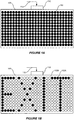
- a solid-state lighting panel 100 may include multiple solid-state light emitters 102.
- the solid-state light emitters 102 may be selectively addressed and/or controlled to provide one or more energized solid-state light emitters 102A and one or more de-energized solid-state light emitters 102B.
- the solid-state light emitters 102 may all be configured to emit light at substantially the same dominant wavelength.
- the solid-state light emitters may be white LED lamps that include a blue-emitting LED coated with a wavelength conversion phosphor that converts some of the blue light emitted by the LED into yellow light. The resulting light, which is a combination of blue light and yellow light, may appear white to an observer.
- a solid-state lighting panel 100 in an illuminating mode to be configured such that all of the solid-state light emitters 102 are energized solid-state lighting emitters 102A to provide general illumination of the proximate area.
- variable levels of lighting may be provided by selectively the energizing a portion of the multiple solid-state light emitters 102 and/or by operating the solid-state light emitters 102 at a reduced current level.
- information may be communicated by selectively operating a portion of the solid-state light emitters 102.
- the solid-state lighting panel 100 may use a communication mode to identify an exit by selectively operating a portion of the solid-state emitters 102 that spell "EXIT".
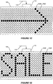
- a suggested route may be identified by selectively operating a portion of the solid-state emitters 102 to form an image of an arrow.
- a solid-state lighting panel 100 may also be used in, for example, a commercial setting to identify a special event and/or activity.
- a commercial event may be identified by selectively operating a portion of the solid-state emitters 102 to spell a word such as "SALE", among others.
- Other, non-illustrated, examples may include a solid-state lighting panel 100 used in a corporate, industrial, institutional, transportation and/or educational environment to indicate event start and stop times and/or status, among others.
- class start and stop times and/or status may be displayed in an educational environment.
- warnings and/or other information may be communicated on a mass transportation vehicle, such as, for example a bus and/or airplane.
- the solid-state light emitters 102 may include a first portion of solid-state light emitters 102 configured to emit light at a first dominant wavelength and a second portion of the solid-state light emitters 102 configured to emit light at a second dominant wavelength.
- the first portion of solid-state light emitters may be operated to provide general illumination and the second portion may be operated to communicate information.
- the first portion of the solid-state light emitters 102 may be configured to emit substantially white light to provide general illumination and the second portion of the solid-state light emitters 102 may be configured to emit substantially red light to indicate a condition such as, for example, fire, earthquake, weather condition, and/or other unsafe conditions and/or events, among others.
- the second portion of the solid-state light emitters 102 may be selectively operated to communicate additional information via an image.
- the solid-state light emitters 102 may be configured as individually addressable multi-color emitters that may deliver substantially white light under normal operation for general illumination.
- the multi-color emitters may be controlled to emit red light, among others. In this manner, in addition to providing text and image based communications, color coded communications may also be provided.
- the solid-state light emitters 102 may be dynamically controlled corresponding to, for example, an image sequence to create the visual effect of motion.
- the solid-state lighting panel 100 may be operated in a hybrid mode wherein a first portion of the solid-state light emitters 102 are operated to provide illumination and a second portion of the solid-state light emitters 102 are operated to communicate information.
- the solid-state lighting panel 100 may also include a multi-mode lighting panel controller 110 that is configured to control the multiple solid-state light emitters 102.
- the multi-mode lighting panel controller 110 may be configured to receive an input signal 112.
- the multi-mode lighting panel controller 110 may select an illumination and/or communication mode responsive to the input signal 112.
- the input signal 112 may be received from, for example, an external system that may transmit the input signal 112 responsive to an alarm, emergency, scheduled event, manual input, and/or environmental sensor, among others.
- a multi-mode illumination apparatus 200 includes a solid-state lighting panel 210.
- the solid-state lighting panel may include multiple solid-state light emitters that may be controlled by a multi-mode lighting panel controller 220.
- the multi-mode lighting panel controller 220 may be configured to control the solid-state light emitters in a first mode to illuminate an area and in a second mode to communicate a message within the area.
- the solid-state light emitters may include multiple first color emitters corresponding to the first mode and multiple second color emitters corresponding to the second mode.
- the solid-state light emitters may include individually addressable multi-color solid-state light emitters that may be configured to emit substantially white light in the first mode and substantially non-white light in a second mode.
- the solid-state light emitters may be operated to provide illumination in the first mode.
- the solid-state light emitters may be selectively operated to display an image that conveys information in the second mode.
- the image may include text and/or a symbol that may be formed through an array selection of specific solid-state light emitters.
- the multi-mode lighting panel controller 220 may include an input module 222 that is configured to receive an input signal.
- the multi-mode lighting panel controller 220 may be configured to select the first mode and/or the second mode responsive to the input signal.
- an input signal may be generated by an external system 230.
- an external system 230 may be event, alarm, and/or schedule based.
- the input module 222 may be configured to receive an input signal from an environment sensor 240.
- an environment sensor 240 may be used to sense temperature and/or smoke in the case of alarm and/or emergency.
- the multi-mode lighting panel controller 220 may be configured to provide an alternative communication, such as information corresponding to an alternate exit route.
- the environment sensor 240 may be a personnel sensor that may be used to trigger a specific communication corresponding to the presence of personnel. For example, in a commercial context, when a customer in a store enters a specific area, a communication regarding a commercial event such as, for example, a sale, special and/or discount may be provided.
- an environment sensor 240 may also provide a signal to the external system 230, which may then send an input signal to the multi-mode lighting panel controller 220.
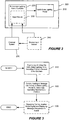
- FIG. 3 is a block diagram illustrating operations according to some embodiments of the present invention.
- Operations include illuminating an area via a solid-state lighting panel that includes first and second color solid-state light emitters (block 310).
- illuminating may be performed by operating all of the first and second color solid-state light emitters.
- the first color solid-state light emitters may emit a substantially white light output.
- the first color solid-state light emitters are blue-emitting LEDs coated with a wavelength conversion phosphor that converts a portion of the emitted light to yellow light.
- the first color solid-state light emitters include multi-color emitters that may each be controlled to deliver white light in an illuminating mode.
- the second color solid-state light emitters may emit a substantially non-white light output.
- red-emitting LEDs may be used in combination with the first color solid-state light emitters to increase a red light energy of the total light output.
- Operations may also include communicating a message via the solid-state lighting panel by selectively operating the second color solid-state light emitters (block 320).
- a portion of the second color solid-state light emitters may be designated to communicate one or more messages using images that may include text and/or symbols.
- a portion of the second color solid-state light emitters may be selected to display the text "EXIT" and/or an arrow symbol to communicate exit and/or egress information.
- the second color solid-state light emitters may each be individually addressable and selectively operated to communicate the message via text, image, and/or color.
- the second color solid-state emitters may be all operated to emit light at a dominant wavelength corresponding to a red color in the case of, for example, a fire and/or other emergency condition.
- the message may be communicated using color coding.
- a red color output may be known to indicate emergency, such as, for example, fire.
- Operations according to some embodiments may include receiving a communication mode signal and displaying a message responsive to the signal (block 330).
- some embodiments may be configured to receive an alarm signal corresponding to an emergency condition and communicate a message corresponding to an exit route and/or status.
- communication mode signal may be used in a commercial context to provide information to potential customers and/or to draw attention to specific features in the commercial environment. By providing general lighting and the capacity for a variety of communications within the same apparatus, separate fixtures for the otherwise independent functions may be avoided.
- FIG. 4 is a block diagram illustrating multiple multi-mode apparatus in a communication mode in accordance with some embodiments of the invention.
- Each of the multi-mode apparatus 400 may include a solid-state lighting panel 410 that includes multiple solid-state light emitters 412.
- the solid-state light emitters 412 may be selectively operated to communicate one or more messages using symbols and/or text.
- the solid-state light emitters 412 may be selectively operated via a multi-mode lighting panel controller 420.
- the multi-mode lighting panel controller 420 may be configured to selectively operate the solid-state emitters 412 responsive to a received input signal.
- multiple multi-mode apparatus 400 may be used in combination with one another to provide coordinated communication. For example, each solid-state lighting panel 410 may communicate a different message corresponding to different locations along an exit and/or egress route.
- the multi-mode lighting panel controller 420 may be configured to receive an input signal from a central controller and/or an external system and/or device and display a message responsive to the received input signal. In some embodiments, the multi-mode lighting panel controller 420 may be configured to receive data from a remote environmental condition sensor and communicate a message responsive to the received data. In some embodiments, the multi-mode lighting panel controller 420 of each of the multi-mode apparatus 400 may provide distributed control of the solid-state light emitters 412 and may function in the absence of a central controller.
- Each of the multi-mode apparatus 500 may include a solid-state lighting panel 510 that includes multiple solid-state light emitters 512.
- the solid-state light emitters 512 may be operated to provide general illumination to an area proximate the multi-mode apparatus 500.
- a maximum illumination may be provided by driving all of the solid-state light emitters 512 at a maximum current and/or duty cycle.
- a dimming function may be provided by driving a portion of the solid-state light emitters 512 and/or by driving the solid-state light emitters 512 at a current and/or duty cycle that is less than the maximum.
- the solid-state light emitters 512 may be selectively operated to communicate one or more messages using symbols and/or text.
- Each of the multi-mode apparatus 500 may include a multi-mode lighting panel controller 520 configured to selectively operate the solid-state light emitters 512.
- the multi-mode lighting panel controller 520 may include an input module configured to receive an input signal 530.
- the input signal 530 may be a signal common to all of the multi-mode apparatus 500.
- the input signal 530 may selectively address each of the multi-mode apparatus 500 independently.
- the multi-mode lighting panel controller 520 may include drivers configured to selectively provide current to the solid-state light emitters 512 and receive control data from a central controller.
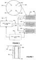
- FIG. 6 is a block diagram illustrating multiple, multi-color multi-mode solid-state lighting panels in accordance with some embodiments of the invention.
- the multi-color multi-mode solid-state lighting panels 600 may be driven by respective multi-mode lighting panel controllers 610 to provide general illumination in a first mode and to communicate one or more messages in a second mode.
- Each of the multi-color multi-mode solid-state lighting panels 600 may include multi-color solid-state light emitters 612.
- the multi-color solid-state light emitters 612 may be configured to emit substantially white light in a first mode and non-white light in the second mode. In the second mode, the multi-color solid-state light emitters 612 may be selectively operated to display an image that conveys information.
- the image may include text and/or one or more symbols that conveys information.
- a sequence of multiple images may be used to generate a light emitting dynamic configuration.
- the multi-color solid-state light emitters 612 may include a substrate 608 on which individual colored LED chips 604-607 may be mounted. For example, a substantially red LED 604, a substantially blue LED 607, and two substantially green LEDs 605, 606 may be mounted on the substrate 608. Each of the individual colored LED chips 604-607 may be individually addressable. By selectively operating the LED chips 604-607, the color of the emitted light may be controlled. For example, all of the LED chips 604-607 may be driven to produce a substantially white light.
- the multi-mode lighting panel controller 610 may be configured to receive input signals 624 from a central lighting panel controller 620. In this manner, multiple lighting panels used in a coordinated manner.
- an environmental condition sensor 640 may be used to provide an environmental information signal to the central lighting panel controller 620 and/or the multi-mode lighting panel controllers 610.
- an environmental condition sensor 640 may be used to detect proximity of potential customers, who may subsequently be exposed to a message via one or more of the lighting panels.
- a multi-mode lighting apparatus 700 includes a two-sided solid-state lighting panel 710 that includes multiple solid-state light emitters 702.
- the two-sided solid-state lighting panel 710 includes a first portion of the solid-state light emitters 702A positioned to emit light in a first direction and a second portion of the solid-state light emitters 702B positioned to emit light in a second direction that is different from the first direction.
- the multi-mode lighting apparatus 700 further includes a multi-mode lighting panel controller 720 that is configured to control the solid-state light emitters 702A, 702B.
- the multi-mode lighting panel controller 720 may be configured to receive an input signal 730 from a central controller, an external system and/or device, and/or an environment sensor, among others.
- the multi-mode lighting apparatus 700 is configured to operate in one or more modes responsive to the input signal 730 received at the multi-mode lighting panel controller 720. For example, the multi-mode lighting apparatus 700 may selectively operate in an illumination mode and/or a communication mode responsive to the input signal 730.
- a first portion of the solid-state light emitters 702A include blue-emitting LEDs coated with a wavelength conversion phosphor and/or LEDs that are configured to emit light having one or more dominant wavelengths.
- the second portion of the solid-state light emitters 702B may include multicolor red, green, blue emitters that are configured to emit light across a broad spectrum.
- the first portion of the solid-state light emitters 702A may operate in an illumination mode while the second portion of the solid-state light emitters 702B may operate in a communication mode.
- the first portion of the solid-state light emitters 702A and the second portion of the solid-state light emitters 702B may both operate in either an illumination mode and/or a communication mode.
- a solid-state lighting panel 800 may include multiple first color solid-state light emitters 802A and multiple second color solid-state light emitters 802B.
- the multiple first color solid-state light emitters 802A may include blue-emitting LEDs coated with a wavelength conversion phosphor.
- the resulting light which is a combination of blue light and yellow light, may appear white to an observer.
- objects illuminated by such light may not appear to have a natural coloring, because of the limited spectrum of the light.
- red colors in an object may not be illuminated well by such light.
- the object may appear to have an unnatural coloring when viewed under such a light source.
- the multiple second color solid-state light emitters 802B may include red-emitting LEDs. In this manner, the illumination provided by the combination of the first color solid-state light emitters 802A and the second color solid-state light emitters 802B may include an increased spectral warmth associated with more energy in the red portion of the visible spectrum.
- a portion of the second color solid-state light emitters 802B may be selectively operated to form an image that is configured to convey information.
- the second color solid-state light emitters 802B may be used to communicate a message via color coding and/or an image. For example, operating only red-emitting LEDs may be indicative of an emergency condition such as a fire, among others.
- spectrally rich light may be provided in an illumination mode and information may be conveyed and/or communicated in a communication mode.
- variable levels of lighting may be provided by selectively energizing portions of the first and/or second color solid-state light emitters 802A and 802B and/or by operating the first and/or second color solid-state light emitters 802A and 802B at reduced current levels.
- FIG. 9 is a block diagram illustrating a multimode apparatus that may be collaboratively operated with similar devices according to some embodiments of the present invention.
- the apparatus may include a solid-state lighting panel 900 that may include multiple solid-state emitters 912 and an input module 910.
- the input module 910 may be configured to receive an input signal from a lighting panel group controller 920.
- the lighting panel group controller 920 may be configured to collaboratively control multiple solid-state lighting panels 900.
- the lighting panel group controller 920 may be configured to collaboratively control the multiple solid-state lighting panels 900 in a first mode to provide illumination and in a second mode to communicate information.
- at least one of the solid-state lighting panels 900 may include multiple first color emitters that correspond to the first mode and multiple second color emitters that correspond to the second mode.
- first color emitters may be configured to emit substantially white light for illumination and second color emitters may be configured to emit light having a dominant wavelength corresponding to the color red. In this manner, in the first mode all solid-state lighting panels 900 may be operated using the first color emitters.
- solid-state lighting panels 900 that correspond to an emergency egress route may be operated using the first color emitters and other, non-route, solid-state lighting panels 900 may be operated using the second color emitters.
- Some embodiments may provide that the solid-state lighting panels 900 are selectively operated in the second mode. For example, solid-state lighting panels 900 that correspond to a route and/or a destination may be operated while other non-route and/or non-destination solid-state lighting panels 900 may be de-energized.
- lighting panel group controller 920 may be configured to collaboratively control the multiple solid-state lighting panels 900 in a dynamic manner corresponding to the second mode.
- solid-state lighting panels 900 that correspond to a route and/or destination may be sequentially operated in a directional manner to indicate the direction of an egress route.
- FIG. 10 is a block diagram illustrating operations according to some embodiments of the present invention.
- An area may be illuminated using multiple solid-state lighting panels in a first mode responsive to an input signal received from a lighting panel group controller (block 1010).
- Information may be communicated by selectively operating a portion of the multiple solid-state lighting panels in a second mode (block 1020).
- the multiple solid-state lighting panels may be selectively operated to indicate a desired route and/or destination. For example, in an emergency condition, selective ones of the solid-state lighting panels may be operated to illuminate and thus identify an egress route.
- the selective operation to the solid-state lighting panels may include a dynamic operation that may indicate a direction of egress as well as a route.
- the solid-state lighting panels may include multi-color light emitters that may be selectively operated to supplement and/or enhance the lighting and/or communication operations.
- the multi-color light emitters may be operated to emit substantially white light in the first mode and substantially non-white light in the second mode.
- a destination such as, for example, an exit door, may be distinctively identified using color and/or a dynamic and/or static operation relative to other of the solid-state lighting panels.
- communicating the information may correspond to a second mode that is responsive to the input signal received by the solid-state lighting panels from the lighting panel group controller.
- the lighting panel group controller includes a building control system, such as, for example, an environmental control system, a communications system, a data network and/or an alarm system, among others.
- the input signal may be generated responsive to data from an environmental sensor (block 1030).
- an environmental sensor may include a smoke, fire, security, weather and/or other emergency condition sensor, among others.
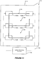
- a system for providing illumination and communication may include multiple solid-state lighting panels 1120A-F that are arranged in a personnel space in a spaced apart manner and that are collaboratively operated responsive to input signals 1132 that are transmitted by a lighting panel group controller 1130.
- the solid-state lighting panels 1120A-F may be collaboratively operated to provide illumination in a first mode and to communicate information in a second mode.
- the solid-state lighting panels 1120A-F may be configured to illuminate a personnel space 1110, such as, for example, an office, laboratory, manufacturing area, retail and/or other type of space designed to be occupied by personnel.
- the personnel space 1110 may include space dividers 1116, such as, for example, partitions and/or walls that are configured to define specific sub-spaces 1114A, B, such as, for example, cubicle spaces, among others.
- the personnel space 1110 may include an exit 1112 that provides egress.
- all of the solid-state lighting panels 1120A-F may be operated to provide a relatively uniform illumination level throughout the personnel space 1110.
- selective ones of the solid-state lighting panels 1120A-F may be operated to communicate information to occupants of the personnel space 1110.
- solid-state lighting panels 1120B, D and F may be operated in the second mode to communicate to occupants the location of the aisle that leads to the exit 1112. In this manner, during, for example, an emergency condition, occupants may be drawn to the aisles by virtue of the operation of the proximate solid-state lighting panels 1120B, D and F while solid-state lighting panels 1120A, C and E are not operated.
- solid-state lighting panels 1120B, D and F may be dynamically operated to provide a flashing sequence that is directed towards the exit 112. Some embodiments provide that solid-state lighting panel 1120B may be operated continuously while solid-state lighting panels 1120D and F may be dynamically operated to indicate the direction of the travel necessary to access the exit 1112. In some embodiments, selective ones of the solid-state lighting panels 1120A-F may be operated to provide substantially non-white light in the second mode. For example, solid-state lighting panels 1120A, C and E may be operated to emit light that includes a dominant wavelength corresponding to a red color.
- the color of light emitted may be specific to the nature of the condition that is being communicated via the collaborative operation of the solid-state lighting panels 1120A-F. For example, light that includes a dominant wavelength corresponding to a blue color may be emitted to indicate a security related condition and/or event. Similarly, light that includes a dominant wavelength corresponding to a red color may be emitted to indicate a fire related condition and/or event.
- the lighting panel group controller 1130 may include a building control system. In some embodiments, the lighting panel group controller 1130 may be configured to generate the input signal and/or change a state of the input signal responsive to an environmental condition sensor (not shown). In some embodiments, the lighting panel group controller 1130 may be configured to dynamically communicate information in the second mode by transmitting a sequence of input signals to the solid-state lighting panels 1120A-F.
- the light emitters within a solid-state lighting panel 1120A-F may be individually addressable, group addressable and/or may not be individually addressable.
- a solid-state lighting panel 1120A-F may be limited to light emitters that are collectively operated responsive to a single signal and/or input.
Landscapes
- Physics & Mathematics (AREA)
- General Physics & Mathematics (AREA)
- Engineering & Computer Science (AREA)
- Theoretical Computer Science (AREA)
- Circuit Arrangement For Electric Light Sources In General (AREA)
- Control Of Indicators Other Than Cathode Ray Tubes (AREA)
- Audible And Visible Signals (AREA)
- Control Of El Displays (AREA)
- Optical Communication System (AREA)
Claims (10)
- Vorrichtung (200), umfassend:eine Festkörper-Leuchttafel (1120), die eine Mehrzahl von Festkörper-Lichtemittern (102) umfasst und konfiguriert ist, um ein Eingangssignal (1132) von einer Leuchttafel-Gruppensteuerung (1130) zu empfangen, die konfiguriert ist, um die Festkörper-Leuchttafel (1120) so zu steuern, dass sie die Beleuchtung über einen Personenaufenthaltsraum (1110) verteilt,wobei das Eingangssignal (1132) einem von einem Personensensor erzeugten Sensorsignal entspricht, oder das Eingangssignal (1132) einem geplanten Ereignis entspricht, undwobei die Festkörper-Leuchttafel (1120) konfiguriert ist, als Reaktion auf das von dem Personensensor erzeugte Sensorsignal oder das dem geplanten Ereignis entsprechende Eingangssignal (1132) selektiv in einem Beleuchtungsmodus zum Beleuchten des Personalaufenthaltsraums (1110) und/oder einem Kommunikationsmodus zum Kommunizieren von Informationen innerhalb des Personalraums (1110) zu arbeiten.
- Vorrichtung nach Anspruch 1, bei der die Festkörper-Leuchttafel (1120) konfiguriert ist, um im Kommunikationsmodus zu arbeiten, um eine spezifische Kommunikation zu erzeugen, die der Anwesenheit von Personen in dem Personenaufenthaltsraum (1110) entspricht.
- Vorrichtung nach Anspruch 1, bei der die Mehrzahl von Festkörper-Lichtemittern (102) einen ersten Teil von Festkörper-Lichtemittern (102), die konfiguriert sind, um im Wesentlichen weißes Licht zu emittieren, und einen zweiten Teil von Festkörper-Lichtemittern (102) umfasst, die konfiguriert sind, um nicht-weißes Licht zu emittieren.
- Vorrichtung nach Anspruch 1, bei der die Mehrzahl von Festkörper-Lichtemittern (102) einen ersten Teil von Festkörper-Lichtemittern (102) und einen zweiten Teil von Festkörper-Lichtemittern (102) umfasst,wobei die Festkörper-Leuchttafel (1120) konfiguriert ist, um in einem Hybridmodus zu arbeiten, der den Beleuchtungsmodus und den Kommunikationsmodus umfasst,bei dem der erste Teil der Mehrzahl von Festkörper-Lichtemittern (102) betrieben wird, um Beleuchtung bereitzustellen, und der zweite Teil der Mehrzahl von Festkörper-Lichtemittern (102) betrieben wird, um Information zu kommunizieren.
- Vorrichtung nach Anspruch 1, bei der die Festkörper-Leuchttafel (1120) konfiguriert ist, als Reaktion auf das dem geplanten Ereignis entsprechende Eingangssignal (1132) eine Dimmfunktion auszuführen, die durch selektives Ansteuern eines Teils der Mehrzahl von Festkörper-Lichtemittern (102) und/oder durch Ansteuern der Mehrzahl von Festkörper-Lichtemittern (102) mit einem elektrischen Strom und/oder einem Tastverhältnis, der/das kleiner als ein maximaler elektrischer Strom und/oder ein maximales Tastverhältnis ist, bereitgestellt wird.
- Vorrichtung nach Anspruch 1, bei der die Festkörper-Leuchttafel (1120) konfiguriert ist, um als Reaktion auf ein auf einem Umgebungssensorsignal basierendes Eingangssignal (1132) eine Dimmfunktion auszuführen, und
wobei die Dimmfunktion durch selektives Ansteuern eines Teils der Mehrzahl von Festkörper-Emittern (102) und/oder durch Ansteuern der Mehrzahl von Festkörper-Lichtemittern (102) mit einem elektrischen Strom und/oder einem Tastverhältnis, der/das kleiner als ein maximaler elektrischer Strom und/oder ein maximales Tastverhältnis ist, bereitgestellt wird. - System zur Bereitstellung von Beleuchtung und Kommunikation, umfassend:eine Mehrzahl von Festkörper-Leuchttafeln (1120A-F), die in einem Innenraum angeordnet sind, der eine Mehrzahl von Unter-Innenräumen umfasst; undeine Leuchttafel-Gruppensteuerung (1130), die konfiguriert ist, um Eingangssignale (1132) an mindestens eine der Mehrzahl von Festkörper-Leuchttafeln (1120A-F) zu übertragen,wobei die Mehrzahl von Festkörper-Leuchttafeln (1120A-F) konfiguriert sind, um in einem Beleuchtungsmodus zum Beleuchten der Mehrzahl von Unterräumen zu arbeiten, und in einem Kommunikationsmodus gemeinsam durch die Leuchttafel-Gruppensteuerung (1130) gesteuert zu werden, um durch selektives Leuchten einer der Mehrzahl von Festkörper-Leuchttafeln (1120A-F) Information zu kommunizieren, undbei dem die Eingangssignale (1132) als Reaktion darauf übertragen werden, dass die Leuchttafel-Gruppensteuerung (1130) ein Umgebungsinformationssignal von einem Umgebungszustandssensor (240) empfängt.
- System nach Anspruch 7, bei dem der Umgebungszustandssensor (240) eine Komponente in einem Gebäudeleitsystem umfasst.
- System nach Anspruch 8, wobei das Gebäudeleitsystem ein Umweltkontrollsystem, ein Kommunikationssystem, ein Datennetzwerk und/oder ein Alarmsystem umfasst.
- Gebäudeleitsystem, wobei das System umfasst:eine Leuchttafel-Gruppensteuerung (1130), die konfiguriert ist, um Eingangssignale (1132) an mindestens eine aus einer Mehrzahl von Festkörper-Leuchttafeln (1120A-F) zu übertragen; undeine Mehrzahl von Sensoren, die konfiguriert sind, um eine Mehrzahl von Sensorsignalen an die Leuchttafel-Gruppensteuerung (1130) zu liefern, wobei die Eingangssignale (1132), die von der Leuchttafel-Gruppensteuerung (1130) übertragen werden, auf einem der Mehrzahl von Sensorsignalen basieren,wobei die Eingangssignale (1132) von der Leuchttafel-Gruppensteuerung (1130) die Mehrzahl von Festkörper-Leuchttafeln (1120A-F) veranlassen, selektiv in einem Beleuchtungsmodus zum Verteilen der Beleuchtung in einem Personenaufenthaltsraum (1110) und einem Kommunikationsmodus zum Kommunizieren von Information durch selektives Leuchten einzelner der Mehrzahl von Festkörper-Leuchttafeln (1120A-F) zu arbeiten.
Priority Applications (1)
| Application Number | Priority Date | Filing Date | Title |
|---|---|---|---|
| EP20200788.6A EP3784005B1 (de) | 2008-03-27 | 2009-03-16 | Vorrichtung, verfahren und systeme zur bereitstellung von licht und kommunikation |
Applications Claiming Priority (2)
| Application Number | Priority Date | Filing Date | Title |
|---|---|---|---|
| US12/056,431 US9930756B2 (en) | 2008-03-27 | 2008-03-27 | Apparatus, methods and systems for providing lighting and communication |
| EP09155205.9A EP2106197B1 (de) | 2008-03-27 | 2009-03-16 | Vorrichtung, Verfahren und Systeme zur Bereitstellung von Licht und Kommunikation |
Related Parent Applications (2)
| Application Number | Title | Priority Date | Filing Date |
|---|---|---|---|
| EP09155205.9A Division EP2106197B1 (de) | 2008-03-27 | 2009-03-16 | Vorrichtung, Verfahren und Systeme zur Bereitstellung von Licht und Kommunikation |
| EP09155205.9A Division-Into EP2106197B1 (de) | 2008-03-27 | 2009-03-16 | Vorrichtung, Verfahren und Systeme zur Bereitstellung von Licht und Kommunikation |
Related Child Applications (2)
| Application Number | Title | Priority Date | Filing Date |
|---|---|---|---|
| EP20200788.6A Division-Into EP3784005B1 (de) | 2008-03-27 | 2009-03-16 | Vorrichtung, verfahren und systeme zur bereitstellung von licht und kommunikation |
| EP20200788.6A Division EP3784005B1 (de) | 2008-03-27 | 2009-03-16 | Vorrichtung, verfahren und systeme zur bereitstellung von licht und kommunikation |
Publications (2)
| Publication Number | Publication Date |
|---|---|
| EP3422820A1 EP3422820A1 (de) | 2019-01-02 |
| EP3422820B1 true EP3422820B1 (de) | 2020-11-18 |
Family
ID=40795050
Family Applications (3)
| Application Number | Title | Priority Date | Filing Date |
|---|---|---|---|
| EP18187121.1A Active EP3422820B1 (de) | 2008-03-27 | 2009-03-16 | Vorrichtung, verfahren und systeme zur bereitstellung von licht und kommunikation |
| EP20200788.6A Active EP3784005B1 (de) | 2008-03-27 | 2009-03-16 | Vorrichtung, verfahren und systeme zur bereitstellung von licht und kommunikation |
| EP09155205.9A Active EP2106197B1 (de) | 2008-03-27 | 2009-03-16 | Vorrichtung, Verfahren und Systeme zur Bereitstellung von Licht und Kommunikation |
Family Applications After (2)
| Application Number | Title | Priority Date | Filing Date |
|---|---|---|---|
| EP20200788.6A Active EP3784005B1 (de) | 2008-03-27 | 2009-03-16 | Vorrichtung, verfahren und systeme zur bereitstellung von licht und kommunikation |
| EP09155205.9A Active EP2106197B1 (de) | 2008-03-27 | 2009-03-16 | Vorrichtung, Verfahren und Systeme zur Bereitstellung von Licht und Kommunikation |
Country Status (3)
| Country | Link |
|---|---|
| US (3) | US9930756B2 (de) |
| EP (3) | EP3422820B1 (de) |
| JP (1) | JP2009282502A (de) |
Families Citing this family (25)
| Publication number | Priority date | Publication date | Assignee | Title |
|---|---|---|---|---|
| US8653984B2 (en) * | 2008-10-24 | 2014-02-18 | Ilumisys, Inc. | Integration of LED lighting control with emergency notification systems |
| EP2583269A4 (de) * | 2010-06-17 | 2014-12-31 | Light Bohrd Llc | Systeme und verfahren für eine leuchtanzeige |
| US20120283878A1 (en) * | 2011-05-06 | 2012-11-08 | Bruce Richard Roberts | Controller and solid state lighting device for large area applications |
| US11792898B2 (en) * | 2012-07-01 | 2023-10-17 | Ideal Industries Lighting Llc | Enhanced fixtures for area lighting |
| US11160148B2 (en) | 2017-06-13 | 2021-10-26 | Ideal Industries Lighting Llc | Adaptive area lamp |
| KR20140110593A (ko) * | 2013-03-08 | 2014-09-17 | 현대자동차주식회사 | 램프를 갖는 차량 |
| US10531545B2 (en) | 2014-08-11 | 2020-01-07 | RAB Lighting Inc. | Commissioning a configurable user control device for a lighting control system |
| US10349488B2 (en) * | 2015-07-17 | 2019-07-09 | Abl Ip Holding Llc | Software configurable lighting device |
| KR20180030876A (ko) | 2015-07-17 | 2018-03-26 | 에이비엘 아이피 홀딩, 엘엘씨 | 소프트웨어 구성가능한 라이팅 디바이스에 구성 데이터를 제공하기 위한 시스템들 및 방법들 |
| JP2017123008A (ja) * | 2016-01-06 | 2017-07-13 | 三菱電機株式会社 | 照明装置、照明制御システム及び避難誘導システム |
| US10412800B1 (en) * | 2016-04-07 | 2019-09-10 | Christopher S. Beattie | Vehicle LED display system |
| US10529696B2 (en) | 2016-04-12 | 2020-01-07 | Cree, Inc. | High density pixelated LED and devices and methods thereof |
| WO2019028314A1 (en) | 2017-08-03 | 2019-02-07 | Cree, Inc. | HIGH DENSITY PIXELIZED LED CHIPS AND NETWORK DEVICES AND METHODS OF MANUFACTURE |
| US10734363B2 (en) | 2017-08-03 | 2020-08-04 | Cree, Inc. | High density pixelated-LED chips and chip array devices |
| US10529773B2 (en) | 2018-02-14 | 2020-01-07 | Cree, Inc. | Solid state lighting devices with opposing emission directions |
| US10991215B2 (en) | 2018-03-20 | 2021-04-27 | Ideal Industries Lighting Llc | Intelligent signage |
| JP2020052529A (ja) * | 2018-09-25 | 2020-04-02 | 京セラドキュメントソリューションズ株式会社 | ネームプレート |
| US10903265B2 (en) | 2018-12-21 | 2021-01-26 | Cree, Inc. | Pixelated-LED chips and chip array devices, and fabrication methods |
| WO2021087109A1 (en) | 2019-10-29 | 2021-05-06 | Cree, Inc. | Texturing for high density pixelated-led chips |
| JP2021158231A (ja) * | 2020-03-27 | 2021-10-07 | 東芝ライテック株式会社 | 光源モジュール及び照明装置 |
| DE102020126196A1 (de) * | 2020-10-07 | 2022-04-07 | Voith Patent Gmbh | Signalsystem |
| US11437548B2 (en) | 2020-10-23 | 2022-09-06 | Creeled, Inc. | Pixelated-LED chips with inter-pixel underfill materials, and fabrication methods |
| CN112542104A (zh) * | 2020-12-30 | 2021-03-23 | 苏州佩林网络科技有限公司 | 智能灯具和智能灯具的控制方法 |
| WO2023050399A1 (zh) * | 2021-09-30 | 2023-04-06 | 华为技术有限公司 | 一种显示控制方法、装置和终端设备 |
| EP4343203A1 (de) | 2022-09-26 | 2024-03-27 | Murrelektronik GmbH | Industrieleuchte |
Family Cites Families (19)
| Publication number | Priority date | Publication date | Assignee | Title |
|---|---|---|---|---|
| JPS5334720B2 (de) * | 1972-03-07 | 1978-09-21 | ||
| JPS59186092A (ja) | 1983-04-06 | 1984-10-22 | 株式会社ウエルウツド | 表示装置 |
| JPH03222202A (ja) | 1990-01-26 | 1991-10-01 | Matsushita Electric Works Ltd | 誘導装置 |
| JPH10326382A (ja) | 1997-05-27 | 1998-12-08 | Matsushita Electric Works Ltd | 避難誘導装置 |
| US7385359B2 (en) * | 1997-08-26 | 2008-06-10 | Philips Solid-State Lighting Solutions, Inc. | Information systems |
| US6380865B1 (en) * | 1999-04-06 | 2002-04-30 | 911 Emergency Products, Inc. | Replacement led lamp assembly and modulated power intensity for light source |
| US6317058B1 (en) * | 1999-09-15 | 2001-11-13 | Jerome H. Lemelson | Intelligent traffic control and warning system and method |
| GB0020766D0 (en) | 2000-08-24 | 2000-10-11 | Rozenberg Simon G | Improvements in lamps luminaires and lighting systems |
| WO2002041276A2 (en) * | 2000-11-15 | 2002-05-23 | Snowy Village, Inc. | Led warning light and communication system |
| US7358929B2 (en) * | 2001-09-17 | 2008-04-15 | Philips Solid-State Lighting Solutions, Inc. | Tile lighting methods and systems |
| US6841947B2 (en) * | 2002-05-14 | 2005-01-11 | Garmin At, Inc. | Systems and methods for controlling brightness of an avionics display |
| JP2006003750A (ja) | 2004-06-18 | 2006-01-05 | Sanyo Electric Co Ltd | Led照明機器 |
| US20080236007A1 (en) * | 2005-01-07 | 2008-10-02 | Kammy Au | Electronic Display Panels for Automobiles |
| US7348736B2 (en) * | 2005-01-24 | 2008-03-25 | Philips Solid-State Lighting Solutions | Methods and apparatus for providing workspace lighting and facilitating workspace customization |
| JP2007171702A (ja) | 2005-12-23 | 2007-07-05 | Mitsumi Electric Co Ltd | 無線発光表示装置 |
| JP5131417B2 (ja) * | 2006-03-15 | 2013-01-30 | 株式会社メガチップス | 照明器による表示システム |
| US20080136334A1 (en) * | 2006-12-12 | 2008-06-12 | Robinson Shane P | System and method for controlling lighting |
| JP5303834B2 (ja) | 2006-12-19 | 2013-10-02 | 日亜化学工業株式会社 | 発光装置 |
| US7690802B2 (en) | 2007-04-17 | 2010-04-06 | Cree, Inc. | Light emitting diode emergency lighting methods and apparatus |
-
2008
- 2008-03-27 US US12/056,431 patent/US9930756B2/en active Active
-
2009
- 2009-03-16 EP EP18187121.1A patent/EP3422820B1/de active Active
- 2009-03-16 EP EP20200788.6A patent/EP3784005B1/de active Active
- 2009-03-16 EP EP09155205.9A patent/EP2106197B1/de active Active
- 2009-03-25 JP JP2009074726A patent/JP2009282502A/ja active Pending
-
2018
- 2018-03-22 US US15/928,866 patent/US10405403B2/en active Active
-
2019
- 2019-08-29 US US16/556,147 patent/US10904988B2/en active Active
Non-Patent Citations (1)
| Title |
|---|
| None * |
Also Published As
| Publication number | Publication date |
|---|---|
| US20180213629A1 (en) | 2018-07-26 |
| US10405403B2 (en) | 2019-09-03 |
| EP3422820A1 (de) | 2019-01-02 |
| US20090241390A1 (en) | 2009-10-01 |
| US20190387599A1 (en) | 2019-12-19 |
| EP2106197A2 (de) | 2009-09-30 |
| EP2106197B1 (de) | 2018-11-28 |
| US10904988B2 (en) | 2021-01-26 |
| EP3784005B1 (de) | 2022-06-29 |
| JP2009282502A (ja) | 2009-12-03 |
| EP3784005A1 (de) | 2021-02-24 |
| US9930756B2 (en) | 2018-03-27 |
| EP2106197A3 (de) | 2014-12-10 |
Similar Documents
| Publication | Publication Date | Title |
|---|---|---|
| US10904988B2 (en) | Apparatus, methods and systems for providing lighting and communication | |
| US10297125B2 (en) | Emergency exit sign | |
| US7125137B2 (en) | Light-emitting unit | |
| US9227564B2 (en) | LED strip lighting device for a cabin of a passenger aircraft | |
| AU2005277287B2 (en) | LED net display | |
| EP1110198B1 (de) | Vorrichtung und verfahren zur bereitstellung eines linearen effekts | |
| EP3552964A1 (de) | Integrierte leuchtende mikro-led-flugzeugtafel | |
| US9249969B2 (en) | Clothing illumination device and clothing illumination system | |
| JP2005537613A5 (de) | ||
| RU2631908C2 (ru) | Устройство и способ для мультиплексирующих по времени переключаемых оптических элементов для управляемого освещения | |
| US9699858B2 (en) | Network controlled multi-color lighting services | |
| CN103765991A (zh) | 自动投用和节能照明系统 | |
| GB2569053A (en) | An emergency exit sign | |
| CN101244786A (zh) | 观光电梯 | |
| US8099261B2 (en) | Low-cost solid-state identification device | |
| WO2005042390A1 (en) | Lighting apparatus of elevator | |
| WO2008121083A1 (en) | Light panel with leds | |
| WO2021069887A1 (en) | Ceiling tile | |
| KR100929164B1 (ko) | 통신 컨버젼스를 통한 led 전광판 및 그 방법 | |
| Blankenbach et al. | 42‐3: Advanced HMIs and Evaluation of Various Display Techniques for Autonomous Robots in Public Spaces | |
| KR102748658B1 (ko) | 서로 다른 구동방식의 다수의 led 출력부를 동시에 운용하는 멀티 전광판 시스템 | |
| CN113310023A (zh) | 厨房插入多用led系统 | |
| CN217386619U (zh) | 一种警示灯装置和运输机器人 | |
| JP2011121769A (ja) | エレベータシステム | |
| JP2006286435A (ja) | 多点光源ユニットおよび照明装置 |
Legal Events
| Date | Code | Title | Description |
|---|---|---|---|
| PUAI | Public reference made under article 153(3) epc to a published international application that has entered the european phase |
Free format text: ORIGINAL CODE: 0009012 |
|
| STAA | Information on the status of an ep patent application or granted ep patent |
Free format text: STATUS: THE APPLICATION HAS BEEN PUBLISHED |
|
| AC | Divisional application: reference to earlier application |
Ref document number: 2106197 Country of ref document: EP Kind code of ref document: P |
|
| AK | Designated contracting states |
Kind code of ref document: A1 Designated state(s): AT BE BG CH CY CZ DE DK EE ES FI FR GB GR HR HU IE IS IT LI LT LU LV MC MK MT NL NO PL PT RO SE SI SK TR |
|
| STAA | Information on the status of an ep patent application or granted ep patent |
Free format text: STATUS: REQUEST FOR EXAMINATION WAS MADE |
|
| 17P | Request for examination filed |
Effective date: 20190528 |
|
| RBV | Designated contracting states (corrected) |
Designated state(s): AT BE BG CH CY CZ DE DK EE ES FI FR GB GR HR HU IE IS IT LI LT LU LV MC MK MT NL NO PL PT RO SE SI SK TR |
|
| RAP1 | Party data changed (applicant data changed or rights of an application transferred) |
Owner name: IDEAL INDUSTRIES LIGHTING LLC |
|
| REG | Reference to a national code |
Ref country code: DE Ref legal event code: R079 Ref document number: 602009063082 Country of ref document: DE Free format text: PREVIOUS MAIN CLASS: H05B0037020000 Ipc: B60Q0001260000 |
|
| GRAP | Despatch of communication of intention to grant a patent |
Free format text: ORIGINAL CODE: EPIDOSNIGR1 |
|
| STAA | Information on the status of an ep patent application or granted ep patent |
Free format text: STATUS: GRANT OF PATENT IS INTENDED |
|
| RIC1 | Information provided on ipc code assigned before grant |
Ipc: B60Q 1/26 20060101AFI20200207BHEP |
|
| GRAJ | Information related to disapproval of communication of intention to grant by the applicant or resumption of examination proceedings by the epo deleted |
Free format text: ORIGINAL CODE: EPIDOSDIGR1 |
|
| STAA | Information on the status of an ep patent application or granted ep patent |
Free format text: STATUS: REQUEST FOR EXAMINATION WAS MADE |
|
| INTG | Intention to grant announced |
Effective date: 20200305 |
|
| INTC | Intention to grant announced (deleted) | ||
| GRAP | Despatch of communication of intention to grant a patent |
Free format text: ORIGINAL CODE: EPIDOSNIGR1 |
|
| STAA | Information on the status of an ep patent application or granted ep patent |
Free format text: STATUS: GRANT OF PATENT IS INTENDED |
|
| INTG | Intention to grant announced |
Effective date: 20200610 |
|
| GRAS | Grant fee paid |
Free format text: ORIGINAL CODE: EPIDOSNIGR3 |
|
| GRAA | (expected) grant |
Free format text: ORIGINAL CODE: 0009210 |
|
| STAA | Information on the status of an ep patent application or granted ep patent |
Free format text: STATUS: THE PATENT HAS BEEN GRANTED |
|
| AC | Divisional application: reference to earlier application |
Ref document number: 2106197 Country of ref document: EP Kind code of ref document: P |
|
| AK | Designated contracting states |
Kind code of ref document: B1 Designated state(s): AT BE BG CH CY CZ DE DK EE ES FI FR GB GR HR HU IE IS IT LI LT LU LV MC MK MT NL NO PL PT RO SE SI SK TR |
|
| REG | Reference to a national code |
Ref country code: GB Ref legal event code: FG4D |
|
| REG | Reference to a national code |
Ref country code: CH Ref legal event code: EP |
|
| RAP2 | Party data changed (patent owner data changed or rights of a patent transferred) |
Owner name: IDEAL INDUSTRIES LIGHTING LLC |
|
| REG | Reference to a national code |
Ref country code: IE Ref legal event code: FG4D |
|
| REG | Reference to a national code |
Ref country code: DE Ref legal event code: R096 Ref document number: 602009063082 Country of ref document: DE |
|
| REG | Reference to a national code |
Ref country code: AT Ref legal event code: REF Ref document number: 1335412 Country of ref document: AT Kind code of ref document: T Effective date: 20201215 |
|
| REG | Reference to a national code |
Ref country code: AT Ref legal event code: MK05 Ref document number: 1335412 Country of ref document: AT Kind code of ref document: T Effective date: 20201118 |
|
| REG | Reference to a national code |
Ref country code: NL Ref legal event code: MP Effective date: 20201118 |
|
| PG25 | Lapsed in a contracting state [announced via postgrant information from national office to epo] |
Ref country code: GR Free format text: LAPSE BECAUSE OF FAILURE TO SUBMIT A TRANSLATION OF THE DESCRIPTION OR TO PAY THE FEE WITHIN THE PRESCRIBED TIME-LIMIT Effective date: 20210219 Ref country code: NO Free format text: LAPSE BECAUSE OF FAILURE TO SUBMIT A TRANSLATION OF THE DESCRIPTION OR TO PAY THE FEE WITHIN THE PRESCRIBED TIME-LIMIT Effective date: 20210218 Ref country code: PT Free format text: LAPSE BECAUSE OF FAILURE TO SUBMIT A TRANSLATION OF THE DESCRIPTION OR TO PAY THE FEE WITHIN THE PRESCRIBED TIME-LIMIT Effective date: 20210318 Ref country code: FI Free format text: LAPSE BECAUSE OF FAILURE TO SUBMIT A TRANSLATION OF THE DESCRIPTION OR TO PAY THE FEE WITHIN THE PRESCRIBED TIME-LIMIT Effective date: 20201118 |
|
| PG25 | Lapsed in a contracting state [announced via postgrant information from national office to epo] |
Ref country code: AT Free format text: LAPSE BECAUSE OF FAILURE TO SUBMIT A TRANSLATION OF THE DESCRIPTION OR TO PAY THE FEE WITHIN THE PRESCRIBED TIME-LIMIT Effective date: 20201118 Ref country code: BG Free format text: LAPSE BECAUSE OF FAILURE TO SUBMIT A TRANSLATION OF THE DESCRIPTION OR TO PAY THE FEE WITHIN THE PRESCRIBED TIME-LIMIT Effective date: 20210218 Ref country code: IS Free format text: LAPSE BECAUSE OF FAILURE TO SUBMIT A TRANSLATION OF THE DESCRIPTION OR TO PAY THE FEE WITHIN THE PRESCRIBED TIME-LIMIT Effective date: 20210318 Ref country code: PL Free format text: LAPSE BECAUSE OF FAILURE TO SUBMIT A TRANSLATION OF THE DESCRIPTION OR TO PAY THE FEE WITHIN THE PRESCRIBED TIME-LIMIT Effective date: 20201118 Ref country code: LV Free format text: LAPSE BECAUSE OF FAILURE TO SUBMIT A TRANSLATION OF THE DESCRIPTION OR TO PAY THE FEE WITHIN THE PRESCRIBED TIME-LIMIT Effective date: 20201118 Ref country code: SE Free format text: LAPSE BECAUSE OF FAILURE TO SUBMIT A TRANSLATION OF THE DESCRIPTION OR TO PAY THE FEE WITHIN THE PRESCRIBED TIME-LIMIT Effective date: 20201118 |
|
| REG | Reference to a national code |
Ref country code: LT Ref legal event code: MG9D |
|
| PG25 | Lapsed in a contracting state [announced via postgrant information from national office to epo] |
Ref country code: HR Free format text: LAPSE BECAUSE OF FAILURE TO SUBMIT A TRANSLATION OF THE DESCRIPTION OR TO PAY THE FEE WITHIN THE PRESCRIBED TIME-LIMIT Effective date: 20201118 |
|
| PG25 | Lapsed in a contracting state [announced via postgrant information from national office to epo] |
Ref country code: EE Free format text: LAPSE BECAUSE OF FAILURE TO SUBMIT A TRANSLATION OF THE DESCRIPTION OR TO PAY THE FEE WITHIN THE PRESCRIBED TIME-LIMIT Effective date: 20201118 Ref country code: CZ Free format text: LAPSE BECAUSE OF FAILURE TO SUBMIT A TRANSLATION OF THE DESCRIPTION OR TO PAY THE FEE WITHIN THE PRESCRIBED TIME-LIMIT Effective date: 20201118 Ref country code: SK Free format text: LAPSE BECAUSE OF FAILURE TO SUBMIT A TRANSLATION OF THE DESCRIPTION OR TO PAY THE FEE WITHIN THE PRESCRIBED TIME-LIMIT Effective date: 20201118 Ref country code: RO Free format text: LAPSE BECAUSE OF FAILURE TO SUBMIT A TRANSLATION OF THE DESCRIPTION OR TO PAY THE FEE WITHIN THE PRESCRIBED TIME-LIMIT Effective date: 20201118 Ref country code: LT Free format text: LAPSE BECAUSE OF FAILURE TO SUBMIT A TRANSLATION OF THE DESCRIPTION OR TO PAY THE FEE WITHIN THE PRESCRIBED TIME-LIMIT Effective date: 20201118 |
|
| REG | Reference to a national code |
Ref country code: DE Ref legal event code: R097 Ref document number: 602009063082 Country of ref document: DE |
|
| PG25 | Lapsed in a contracting state [announced via postgrant information from national office to epo] |
Ref country code: DK Free format text: LAPSE BECAUSE OF FAILURE TO SUBMIT A TRANSLATION OF THE DESCRIPTION OR TO PAY THE FEE WITHIN THE PRESCRIBED TIME-LIMIT Effective date: 20201118 |
|
| PLBE | No opposition filed within time limit |
Free format text: ORIGINAL CODE: 0009261 |
|
| STAA | Information on the status of an ep patent application or granted ep patent |
Free format text: STATUS: NO OPPOSITION FILED WITHIN TIME LIMIT |
|
| 26N | No opposition filed |
Effective date: 20210819 |
|
| PG25 | Lapsed in a contracting state [announced via postgrant information from national office to epo] |
Ref country code: NL Free format text: LAPSE BECAUSE OF FAILURE TO SUBMIT A TRANSLATION OF THE DESCRIPTION OR TO PAY THE FEE WITHIN THE PRESCRIBED TIME-LIMIT Effective date: 20201118 Ref country code: MC Free format text: LAPSE BECAUSE OF FAILURE TO SUBMIT A TRANSLATION OF THE DESCRIPTION OR TO PAY THE FEE WITHIN THE PRESCRIBED TIME-LIMIT Effective date: 20201118 |
|
| REG | Reference to a national code |
Ref country code: CH Ref legal event code: PL |
|
| PG25 | Lapsed in a contracting state [announced via postgrant information from national office to epo] |
Ref country code: SI Free format text: LAPSE BECAUSE OF FAILURE TO SUBMIT A TRANSLATION OF THE DESCRIPTION OR TO PAY THE FEE WITHIN THE PRESCRIBED TIME-LIMIT Effective date: 20201118 |
|
| REG | Reference to a national code |
Ref country code: BE Ref legal event code: MM Effective date: 20210331 |
|
| PG25 | Lapsed in a contracting state [announced via postgrant information from national office to epo] |
Ref country code: ES Free format text: LAPSE BECAUSE OF FAILURE TO SUBMIT A TRANSLATION OF THE DESCRIPTION OR TO PAY THE FEE WITHIN THE PRESCRIBED TIME-LIMIT Effective date: 20201118 Ref country code: LU Free format text: LAPSE BECAUSE OF NON-PAYMENT OF DUE FEES Effective date: 20210316 Ref country code: IE Free format text: LAPSE BECAUSE OF NON-PAYMENT OF DUE FEES Effective date: 20210316 Ref country code: LI Free format text: LAPSE BECAUSE OF NON-PAYMENT OF DUE FEES Effective date: 20210331 Ref country code: CH Free format text: LAPSE BECAUSE OF NON-PAYMENT OF DUE FEES Effective date: 20210331 |
|
| PG25 | Lapsed in a contracting state [announced via postgrant information from national office to epo] |
Ref country code: IS Free format text: LAPSE BECAUSE OF FAILURE TO SUBMIT A TRANSLATION OF THE DESCRIPTION OR TO PAY THE FEE WITHIN THE PRESCRIBED TIME-LIMIT Effective date: 20210318 |
|
| PG25 | Lapsed in a contracting state [announced via postgrant information from national office to epo] |
Ref country code: BE Free format text: LAPSE BECAUSE OF NON-PAYMENT OF DUE FEES Effective date: 20210331 |
|
| PGFP | Annual fee paid to national office [announced via postgrant information from national office to epo] |
Ref country code: FR Payment date: 20230327 Year of fee payment: 15 |
|
| PG25 | Lapsed in a contracting state [announced via postgrant information from national office to epo] |
Ref country code: CY Free format text: LAPSE BECAUSE OF FAILURE TO SUBMIT A TRANSLATION OF THE DESCRIPTION OR TO PAY THE FEE WITHIN THE PRESCRIBED TIME-LIMIT Effective date: 20201118 |
|
| PGFP | Annual fee paid to national office [announced via postgrant information from national office to epo] |
Ref country code: IT Payment date: 20230321 Year of fee payment: 15 Ref country code: GB Payment date: 20230327 Year of fee payment: 15 |
|
| PG25 | Lapsed in a contracting state [announced via postgrant information from national office to epo] |
Ref country code: HU Free format text: LAPSE BECAUSE OF FAILURE TO SUBMIT A TRANSLATION OF THE DESCRIPTION OR TO PAY THE FEE WITHIN THE PRESCRIBED TIME-LIMIT; INVALID AB INITIO Effective date: 20090316 |
|
| PG25 | Lapsed in a contracting state [announced via postgrant information from national office to epo] |
Ref country code: MK Free format text: LAPSE BECAUSE OF FAILURE TO SUBMIT A TRANSLATION OF THE DESCRIPTION OR TO PAY THE FEE WITHIN THE PRESCRIBED TIME-LIMIT Effective date: 20201118 |
|
| PG25 | Lapsed in a contracting state [announced via postgrant information from national office to epo] |
Ref country code: TR Free format text: LAPSE BECAUSE OF FAILURE TO SUBMIT A TRANSLATION OF THE DESCRIPTION OR TO PAY THE FEE WITHIN THE PRESCRIBED TIME-LIMIT Effective date: 20201118 |
|
| PG25 | Lapsed in a contracting state [announced via postgrant information from national office to epo] |
Ref country code: MT Free format text: LAPSE BECAUSE OF FAILURE TO SUBMIT A TRANSLATION OF THE DESCRIPTION OR TO PAY THE FEE WITHIN THE PRESCRIBED TIME-LIMIT Effective date: 20201118 |
|
| GBPC | Gb: european patent ceased through non-payment of renewal fee |
Effective date: 20240316 |
|
| REG | Reference to a national code |
Ref country code: DE Ref legal event code: R081 Ref document number: 602009063082 Country of ref document: DE Owner name: CREE LIGHTING USA LLC (N.D.GES.D. STAATES DELA, US Free format text: FORMER OWNER: IDEAL INDUSTRIES LIGHTING LLC, SYCAMORE, IL, US |
|
| PG25 | Lapsed in a contracting state [announced via postgrant information from national office to epo] |
Ref country code: GB Free format text: LAPSE BECAUSE OF NON-PAYMENT OF DUE FEES Effective date: 20240316 |
|
| PG25 | Lapsed in a contracting state [announced via postgrant information from national office to epo] |
Ref country code: FR Free format text: LAPSE BECAUSE OF NON-PAYMENT OF DUE FEES Effective date: 20240331 |
|
| PG25 | Lapsed in a contracting state [announced via postgrant information from national office to epo] |
Ref country code: GB Free format text: LAPSE BECAUSE OF NON-PAYMENT OF DUE FEES Effective date: 20240316 Ref country code: FR Free format text: LAPSE BECAUSE OF NON-PAYMENT OF DUE FEES Effective date: 20240331 |
|
| PGFP | Annual fee paid to national office [announced via postgrant information from national office to epo] |
Ref country code: DE Payment date: 20250327 Year of fee payment: 17 |
|
| PG25 | Lapsed in a contracting state [announced via postgrant information from national office to epo] |
Ref country code: IT Free format text: LAPSE BECAUSE OF NON-PAYMENT OF DUE FEES Effective date: 20240316 |