EP3422870B1 - Procédé et système pour découpler une pression de vapeur de la température pour commander le cisaillement transmis au flux de produit - Google Patents
Procédé et système pour découpler une pression de vapeur de la température pour commander le cisaillement transmis au flux de produit Download PDFInfo
- Publication number
- EP3422870B1 EP3422870B1 EP17711907.0A EP17711907A EP3422870B1 EP 3422870 B1 EP3422870 B1 EP 3422870B1 EP 17711907 A EP17711907 A EP 17711907A EP 3422870 B1 EP3422870 B1 EP 3422870B1
- Authority
- EP
- European Patent Office
- Prior art keywords
- steam
- product
- pressure
- supply
- control
- Prior art date
- Legal status (The legal status is an assumption and is not a legal conclusion. Google has not performed a legal analysis and makes no representation as to the accuracy of the status listed.)
- Active
Links
Images


Classifications
-
- A—HUMAN NECESSITIES
- A47—FURNITURE; DOMESTIC ARTICLES OR APPLIANCES; COFFEE MILLS; SPICE MILLS; SUCTION CLEANERS IN GENERAL
- A47J—KITCHEN EQUIPMENT; COFFEE MILLS; SPICE MILLS; APPARATUS FOR MAKING BEVERAGES
- A47J27/00—Cooking-vessels
- A47J27/04—Cooking-vessels for cooking food in steam; Devices for extracting fruit juice by means of steam ; Vacuum cooking vessels
-
- A—HUMAN NECESSITIES
- A23—FOODS OR FOODSTUFFS; TREATMENT THEREOF, NOT COVERED BY OTHER CLASSES
- A23B—PRESERVATION OF FOODS, FOODSTUFFS OR NON-ALCOHOLIC BEVERAGES; CHEMICAL RIPENING OF FRUIT OR VEGETABLES
- A23B2/00—Preservation of foods or foodstuffs, in general
- A23B2/003—Control or safety devices for sterilisation or pasteurisation systems
-
- A—HUMAN NECESSITIES
- A23—FOODS OR FOODSTUFFS; TREATMENT THEREOF, NOT COVERED BY OTHER CLASSES
- A23B—PRESERVATION OF FOODS, FOODSTUFFS OR NON-ALCOHOLIC BEVERAGES; CHEMICAL RIPENING OF FRUIT OR VEGETABLES
- A23B2/00—Preservation of foods or foodstuffs, in general
- A23B2/40—Preservation of foods or foodstuffs, in general by heating loose unpacked materials
- A23B2/42—Preservation of foods or foodstuffs, in general by heating loose unpacked materials while they are progressively transported through the apparatus
- A23B2/46—Preservation of foods or foodstuffs, in general by heating loose unpacked materials while they are progressively transported through the apparatus with transport through tubes
-
- A—HUMAN NECESSITIES
- A23—FOODS OR FOODSTUFFS; TREATMENT THEREOF, NOT COVERED BY OTHER CLASSES
- A23L—FOODS, FOODSTUFFS OR NON-ALCOHOLIC BEVERAGES, NOT OTHERWISE PROVIDED FOR; PREPARATION OR TREATMENT THEREOF
- A23L5/00—Preparation or treatment of foods or foodstuffs, in general; Food or foodstuffs obtained thereby; Materials therefor
- A23L5/10—General methods of cooking foods, e.g. by roasting or frying
- A23L5/13—General methods of cooking foods, e.g. by roasting or frying using water or steam
-
- A—HUMAN NECESSITIES
- A47—FURNITURE; DOMESTIC ARTICLES OR APPLIANCES; COFFEE MILLS; SPICE MILLS; SUCTION CLEANERS IN GENERAL
- A47J—KITCHEN EQUIPMENT; COFFEE MILLS; SPICE MILLS; APPARATUS FOR MAKING BEVERAGES
- A47J27/00—Cooking-vessels
- A47J27/04—Cooking-vessels for cooking food in steam; Devices for extracting fruit juice by means of steam ; Vacuum cooking vessels
- A47J2027/043—Cooking-vessels for cooking food in steam; Devices for extracting fruit juice by means of steam ; Vacuum cooking vessels for cooking food in steam
-
- A—HUMAN NECESSITIES
- A47—FURNITURE; DOMESTIC ARTICLES OR APPLIANCES; COFFEE MILLS; SPICE MILLS; SUCTION CLEANERS IN GENERAL
- A47J—KITCHEN EQUIPMENT; COFFEE MILLS; SPICE MILLS; APPARATUS FOR MAKING BEVERAGES
- A47J27/00—Cooking-vessels
- A47J27/02—Cooking-vessels with enlarged heating surfaces
- A47J27/024—Cooking-vessels with enlarged heating surfaces with liquid-heating tubes extending outside the vessel
Definitions
- the present disclosure generally relates to a method and system for heating or cooking a product utilizing steam. More particularly, the present disclosure relates to a system and method that control the pressure of steam, the amount of steam injected into the product flow and the pressure of the product flow to repeatably control the shear imparted on the product flow.
- the shear imparted on the food from the velocity of the steam impacting the process fluid cannot be changed.
- US4,752,487A relates to a process for the automatic control of the temperature of a food product continuously heated by the direct injection of steam.
- the heating of the food to the required temperature involves controlling the supply of the food product to the steam injector, and controlling the quantity of steam to the steam injector for injection.
- US 2004/0188869 A1 relates to direct contact steam injection heaters that use full pressure steam for heating certain types of slurries that contain abrasive material. This is achieved via small jets of steam injected via a plurality of steam injection holes.
- the amount of steam supplied may be modulated by moving an adjustable cover to expose a selected number of steam diffusion holes.
- the present disclosure provides a system, as defined in claim 1, and a method, as defined in claim 13, to decouple steam pressure from temperature of food using direct steam injection to repeatably control the shear imparted to food.
- the present disclosure utilizes a plurality of steam injection heaters/cookers, such as available from Hydro-Thermal Corporation and shown in U.S. Patent No. 7,025,338 to cook a product flow.
- the steam injection heaters/cookers of the present disclosure have the ability to control shear by utilizing a steam modulator to vary the steam orifices. This control is an extension of the internal modulation technology, whereby high pressure steam is connected directly to the system steam header.
- the supply of steam is passed through a pressure control valve, which modulates the steam pressure to the plurality of steam injection heaters/cookers through PID control using a pressure transmitter as feedback.
- This control system provides the system of the present disclosure the ability to set the pressure of the steam supplied to the product flow, vary the steam orifices, and recall that same pressure every time that particular recipe is loaded in the specialized software.
- Fig. 1 illustrates a cooking system 10 constructed in accordance with the present disclosure.
- the cooking system 10 is designed to cook a product flow as the product flow enters into a product supply pipeline 12 and flows from a product input 14 to a product output 16.
- the product supply pipeline 12 has generally constant diameter as the product supply pipeline 12 extends from the product input 14 to the product output 16.
- the product flow can be a wide variety of products, but is contemplated in the preferred embodiment as being a liquid food product, such as soups, sauces or other liquid based food product that needs to be cooked.
- a plurality of steam injection cookers 18 are positioned along the length of the product supply pipeline 12.
- two steam injection cookers 18 are located along the length of the product supply pipeline 12.
- additional steam injection cookers 18 could be utilized.
- the cooking system 10 of the present disclosure is designed to be modular such that additional cookers 18 and additional sections of the product supply pipeline can be added.
- the steam-based injection heaters/cookers are Infuze® heaters sold and manufactured by Hydro-Thermal Corporation.
- the specific configuration of the steam injection cookers/heaters 18 is shown in U.S. Patent 7,025,338 .
- other types of steam injection cookers could be utilized while operating within the scope of the present disclosure.
- a control unit 20 is positioned as part of the cooking system 10.
- the control unit 20 can be located at various different locations.
- the control unit 20 is mounted to the support frame 22 at a general central location along the overall length of the cooking system 10.
- the control unit 20 can include varies different types of processing devices and should be interpreted as such.
- the product flow enters into the product supply pipeline 12 at the inlet 14 and is received by a three-way diverter valve 25.
- the position of the three-way diverter valve 25 is controlled by the control unit 20. In a first position, the product flow travels through the remaining portions of the product supply pipeline 12. In a second position, the flow of liquid received at the inlet 14 is directed into the upper portion of the valve and to the transfer line 27, shown in Fig. 2 . The second position is useful for cleaning, as will be described in detail below.
- a valve 29 allows for only one directional flow to the steam supply pipeline 24.
- the cooking system 10 includes a steam supply pipeline 24.
- the steam supply pipeline 24 receives a supply of steam at a supply pressure at the steam inlet 26.
- the steam inlet 26 enters into a steam pressure control valve 28.
- the steam pressure control valve 28 is a control valve that is operable to selectively modify the pressure of the steam as the steam passes from the steam inlet 26 to a steam outlet 30.
- the pressure of the steam at the steam outlet 30 will be at a regulated pressure controlled by the control unit 20 through feedback from the pressure sensor 31 shown in Fig. 2 .
- the regulated pressure of the supply of steam at the steam outlet 30 is then fed to the remaining portion of the steam supply pipeline 24.
- each of the steam injection cookers 18 includes a product input 32, a product output 34 and a steam inlet 36.
- a steam modulator (not shown) is included within the heater body to control the amount of steam injected into the product flow as the product flow passes from the product input 32 to the product output 34.
- the control unit 20 is connected to each of the steam injection cookers 18 such that the control unit 20 can control the position of the steam modulator. By controlling the position of the steam modulator, the control unit 20 is able to control the amount of shear impacted on the product flow as the product flow passes through the steam injection cooker and control the temperature of the product flow.
- a back pressure valve 38 is positioned near the product outlet 16 of the product supply pipeline 12.
- the back pressure valve 38 is operatively controlled by the control unit 20.
- the back pressure valve 38 controls the pressure of the product flow within the portions of the product supply pipeline 12 upstream from the back pressure valve 38.
- the control unit 20 is able to create and maintain a differential pressure between the pressure of the product flow through each of the steam injection cookers and the regulated pressure of steam entering into the steam injection cooker.
- the product flow can be heated to a temperature above a flash temperature of 100°C (212°F).
- the system further includes an outflow valve 40 ( Fig. 2 ) located near the product output 16 of the product supply pipeline 12.
- the outflow valve 40 can be automated to redirect product flow as the product leaves the product outlet 16.
- the support frame 22 includes a plurality of tubular sections that provide the required support for the components of the cooking system.
- a series of clamps 42 support both the product supply pipeline 12 and the steam supply pipeline 24.
- the support frame 22 includes a plurality of feet 44 that allow the support frame 22 to be supported upon an uneven surface.
- a cleaning solution supply can be connected to the product inlet 14 and directed through both the product supply pipeline 12 and the steam pipeline 24 through control of the three-way diverter valve 25.
- the control unit 20 can control the position of the diverter valve 25 such that either the steam from inlet 26 or the cleaning solution received at the product inlet 14 can be directed into the steam supply pipeline 24.
- the cleaning solution passes through each of the steam injection cookers to clean both the steam injection cookers, the steam pipeline and the product supply pipeline.
- the system is a clean-in-place system that does not require the removal of any elements, including the steam injection cookers.
- the portion of the product supply pipeline 12 connecting the two steam injection cookers 18 has an S-shape that includes a first curved section 48 and a second curved section 50.
- the first and second curved sections 48, 50 increase the heating and mixing as the product flow passes between the steam injection cookers 18.
- Fig. 2 illustrates the operative and control connections between the elements shown in Fig. 1 and described above.
- the control unit 20 includes an Ethernet connection 52 such that the control unit 20 can communicate to monitoring or control systems at remote locations. In this manner, the operation of the cooking system 10 can be managed, controlled and monitored either locally or remotely.
- the supply of steam 54 is supplied as an input to the steam supply pipeline 24.
- the supply of steam enters into the steam pressure control valve 28 which is operable by the control unit 20 to regulate the pressure of steam to a regulated steam supply pressure.
- the steam supply pipeline 24 includes multiple branches 56 that are each connected to a steam inlet 36 for one of the plurality of steam injection cookers 18.
- each of the steam injection cookers 18 includes a steam modulator that controls the amount of steam injected into the product flow contained within the product supply pipeline 12.
- the product supply pipeline 12 includes the back pressure valve 38 which is operated by the control unit 20 to control the pressure of the product flow within the product supply pipeline 12 upstream from the back pressure valve 38.
- a pressure sensor 58 is positioned upstream from the back pressure valve 38. The pressure sensor 58 communicates with the control unit 20 so that the control unit 20 can monitor the pressure of the product flow before the back pressure valve 38.
- An outflow valve 40 is located at the termination of the product supply pipeline 12 and can be operated by the control unit 20 to direct the product flow leaving the cooking system 10.
- the back pressure valve 38 also controls the amount of shear imparted due to depressurization of the process fluid after the leaving the steam based cooking system. This is measured as the difference between the induced pressure within the steam based cooking system 10 and the nominal line pressure after the cooking system 10. This allows a control paradigm where a set of control parameters can create a visual look and texture effect on a given recipe and then be repeated at different production facilities, even with different nominal line pressures. The control of both the steam pressure and the modulation of the cookers 18 allows for this repeatable design and use at multiple different facilities.
- the system of the present disclosure adds internal modulation technology to create a steady temperature rise +/- 0.55°C (+/- 1°F). at both low shear conditions and high shear conditions.
- the amount of shear can be controlled based both on the steam pressure and the amount of modulation in each of the cookers 18.
- the mechanism of disclosure here described couples steam pressure control to a fixed pressure differential for the shear effect on a fluid.
- the cooking system 10 utilizes the temperature controls inherit through a modulating orifice size steam injection cooker 18.
- targeted shear levels can be achieved by manipulating pressure differentiation of steam and fluid, and in absolute positions.
- the shear imparted on the product flow is imparted from the velocity of the steam injection process. This velocity impacts the product flow in a controlled way, through the steam injection cookers 18, and yields a repeatable amount of shear affect on the liquid food product flow. This is different than externally modulated devices in that the high steam pressure generates a higher level of kinetic energy and thus a wider range of effective shear profiles on the food.
- the shear imparted on the product flow from point one is added to the shear imparted from back pressure control onto the fluid. This yields a total amount of shear (or energy) imparted into the product flow. This total energy is added on a recipe basis to allow both intended and repeatable shear effect which can only be achieved in the cooking system 10 of the present disclosure.
- the pathway is only half of the cleaning action, the other half is the software controls in the control unit 20 that function to correctly clean the cooking system without introducing food particles into the steam line.
- the PLC of the control unit 20 is coded with a cleaning routine such that water is rinsed through the process piping and, using information from a conductivity sensor, the program determines when rinsing is complete. As rinsing is ongoing, the conductivity of the fluid passing over the conductivity sensor changes, which is monitored by the control unit 20.
- the bypass line is opened and the water is rinsed through the steam piping and, using information from a conductivity sensor, the program determines when rinsing is complete. During this process, the program opens and closes the steam cookers in an optimal pattern to ensure proper rinsing of the internals of each of the cookers 18.
- Detergent is introduced into the cooking system 10 of the present disclosure and the program operating on the control unit 20 directs the flow of the solution through the steam and process piping while the cookers are being open and closed. Utilizing feedback from all of the built-in sensors, the program determines when cleaning is complete.
- Water is then rinsed through the process and steam piping while the cookers are being open and closed.
- the program determines when rinsing is complete. Washing and rinsing steps can be repeated for different detergents.
- the construction of the cooking system 10 of the present disclosure is in an S-shape and steam delivery system from overhead creates a compact, close coupled and sanitary system.
- the dimensions of the "S" section were designed such that it is a repeatable section. Since the length of the system is not defined - there can essentially be any number of cooking sections, holding sections, or control sections in the any given system
- This design was also chosen to create a linear array of control points. All of the cooking sections are in a straight line as shown in Fig. 1 , which allows the steam service to produce the least steam pressure drop to each cooking zone.
- the temperature control transmitters are in a line such that it yields a repeatable section in the supporting conduit line to run the data cables back to the main control cabinet.
- Modular design allows for hold tube arrays where the reconnection point is immediately next to the subsequent control point.
- the "S" sections can open up to form a "U” section at any point (between cookers or after the final cooker) to connection to any intermediate processor (hold tube, hold tank, mixer, homogenizer, etc.) of any length due to the inherent "S" shape, and then reconnect back to the system piping to continue processing in the system of the present disclosure.
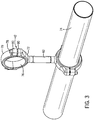
- the pipe clamps 42 each include a first half 70 and a second half 72 that surround the outer diameter of the pipe section 74.
- Each of the first and second halves 70, 72 include an inner liner 76 that contacts the outer surface of the pipe section 74.
- the first and second clamp halves 70, 72 are joined by threaded connectors 78 received within outer connective portions 80. The connectors 78 can be rotated to increase or decrease the clamping pressure on the outer diameter of the pipe section 74.
- a support portion 82 connects a pair of the clamps 42 to support one pipeline relative to another pipeline.
- the clamps 42 allow the pipe sections to be supported by the support frame without the need for welded connections, which can create voids. This allows for a completely sealed connection to the frame which disallows microbial growth, but offers two new key benefits.
- the first benefit is that the support frame and components can be disassembled in the field and the modifications can be performed on the system with no welding. This is an important feature since welding has been shown to create pinholes and hardening which lead to cracks that form hygiene problems in a food plant.
- the clamps 42 for a complete seal around the pipe made of food grade silicone. This silicone allows a certain degree of deflection such that the natural harmonic vibrations inherent in steam injection is dampened and not transferred to throughout the system.
- the clamping system additionally allows for the installation of accessories and add-ons (like operator guards) to the system without welding or skilled labor.
- Another feature of the present disclosure is the use of an ancillary tubing system that contains within a sealed mechanism the wiring and cable harness to components leaving pockets and bacteria traps minimized to a short pigtail position on the instrument it is controlling.
- the standard wire bundles in the food industry are not ideal as they hold water (through capillary action) between the cables in the bundle.
- the standing water promotes microbial growth and creates a difficult to clean area.
- the conduit system of the present disclosure was designed specifically to control the wiring and air tubing with as few penetrations into the control cabinet as possible, while additionally creating single wires and air tubing exiting the conduit system to maintain the overall hygiene of the external system. This prevents microbial growth by removing areas where capillary action with retain water, and also exposing every individual cable for ease of cleaning.
- Yet another feature of the present disclosure is that the delivery of the control system is made available through local and internet protocol access appropriately and permissions.
- remote monitoring allows production to be run while management tasks like throughput, quality, and recipe planning can be run concurrently.
- the control paradigm of the system of the present disclosure is such that any parameter of control of the system can be accomplished through the same interface screen 62 on the control unit 20 while running. This allows user accounts with elevated permissions to log into the system without stopping the system or changing screens, and make changes to the behavior of the system (such as speed of reaction, order of control, and alarming) without stopping production. The result is that the system has a very intuitive, natural and powerful interface from which all run functions can be completed.
- a distributed control system computer control system
- the cooking system 10 of the present disclosure can also be controlled to prevent overshooting during major process variation.
- the system software senses changes in the incoming process conditions using a combination of flow and temperature sensor feedback. Using this information, the program pre-emptively reacts to the changes to prevent large overshoots or undershoots in temperature as a result of the changes in process conditions. This is beneficial as standard food equipment would result in product damage to high temperature spikes, or loss of aseptic conditions due to under cooked foods.
- the cooking system 10 has a very complex control system with obfuscated logic controlled by the manufacturer. This logic is special due to the way the four control loops affect each other during the production process.
- the control loops are:
- a pump is used to initiate product flow and the set flow rate of the product flow is controlled by the program using feedback from the flowmeter and through trend data from the run history. This product flow reaches an equilibrium at the setpoint, and in itself, is simple to control.
- the second loop is the product back pressure valve, which will restrict product flow to increase the pressure in the product piping system.
- This back pressure valve 38 is controlled by the program using feedback from the product pressure transmitting sensor, but at the same time reduces the flow, so the flow PID loop has to re-calculate the new equilibrium.
- Steam Pressure is then turned on and is controlled by the program using the steam pressure valve 28 and feedback from the steam pressure transmitting sensor. However, this added pressure affects the back pressure, which in turn affects the flow, and the system of loops must re-equilibrate.
Landscapes
- Engineering & Computer Science (AREA)
- Life Sciences & Earth Sciences (AREA)
- Food Science & Technology (AREA)
- Chemical & Material Sciences (AREA)
- Polymers & Plastics (AREA)
- Wood Science & Technology (AREA)
- Zoology (AREA)
- Health & Medical Sciences (AREA)
- Nutrition Science (AREA)
- Commercial Cooking Devices (AREA)
- Cleaning By Liquid Or Steam (AREA)
Claims (17)
- Système de cuisson (10) permettant de cuire un produit, comprenant :une alimentation en vapeur fournie à une pression d'alimentation ;une vanne de commande de pression de vapeur (28) présentant une entrée permettant de recevoir l'alimentation en vapeur à la pression d'alimentation et une sortie commandée permettant de fournir l'alimentation en vapeur à une pression régulée ;un conduit d'alimentation en vapeur (24) permettant de fournir l'alimentation en vapeur à la pression régulée ;une pluralité de cuiseurs à injection de vapeur (18) présentant chacun une entrée de produit (32), une sortie de produit (34), une entrée de vapeur (36) et un modulateur de vapeur, dans lequel l'entrée de vapeur reçoit l'alimentation en vapeur à la pression régulée ; etun conduit d'alimentation en produit (12) présentant une entrée de produit (14) et une sortie de produit (16), dans lequel le conduit d'alimentation en produit reçoit un flux de produit du produit au niveau de l'entrée de produit, dans lequel la pluralité de cuiseurs à injection de vapeur sont situés le long du conduit d'alimentation en produit pour chauffer le flux de produit à mesure que le produit s'écoule vers la sortie du produit ; etune unité de commande (20) pouvant fonctionner afin de commander la vanne de commande de pression de vapeur et le modulateur de vapeur.
- Système de cuisson selon la revendication 1, comprenant en outre une vanne de contre-pression (38) et un capteur de pression de produit (31) positionné au niveau de l'entrée de produit (14) vers le conduit d'alimentation en produit (12), dans lequel la vanne de contre-pression peut être actionnée pour commander la pression du produit dans le conduit d'alimentation en produit en aval de la vanne de contre-pression.
- Système de cuisson selon la revendication 2, comprenant en outre une unité de commande (20) pouvant fonctionner pour commander la vanne de commande de pression de vapeur (28) et le modulateur de vapeur, dans lequel l'unité de commande est couplée à la vanne de contre-pression (38) et au capteur de pression de produit (31) et peut être actionnée pour commander la position du capteur de contre-pression (58) sur la base de la pression déterminée du flux de produit provenant du capteur de pression de produit.
- Système de cuisson selon la revendication 3, dans lequel l'unité de commande (20) peut fonctionner pour commander la pression différentielle entre la pression régulée de l'alimentation en vapeur et la pression régulée du flux de produit, ou dans lequel l'unité de commande (20) peut fonctionner pour commander la vanne de commande de pression de vapeur (28) et le modulateur de vapeur pour commander une quantité de cisaillement créée par les cuiseurs à injection de vapeur (18).
- Système de cuisson selon la revendication 1, dans lequel le conduit d'alimentation en produit (12) inclut une pluralité de parties de connexion en forme de S positionnées entre une sortie de produit (34) de l'un des cuiseurs à injection de vapeur (18) et une entrée de produit (32) d'un autre de la pluralité de cuiseurs à injection de vapeur.
- Système de cuisson selon la revendication 3, comprenant en outre une vanne de flux de sortie (40) située à la sortie du conduit d'alimentation en produit (12), dans lequel l'unité de commande (20) peut fonctionner pour commander la direction d'écoulement du flux de produit quittant la sortie du conduit d'alimentation en produit.
- Système de cuisson selon la revendication 1, comprenant en outre une ligne d'alimentation en solution de nettoyage incluant une alimentation en solution de nettoyage, dans lequel soit l'alimentation en vapeur soit la solution de nettoyage est alimentée vers le conduit de vapeur.
- Système de cuisson selon la revendication 7, dans lequel le fonctionnement des cuiseurs à injection de vapeur (18) est commandé pour nettoyer les cuiseurs à injection de vapeur et l'agencement de tuyauterie d'alimentation en vapeur lorsque la ligne d'alimentation en solution de nettoyage est alimentée vers le conduit de vapeur, et comprenant en outre facultativement au moins un capteur de nettoyage pouvant fonctionner pour mesurer la conductivité de la solution de nettoyage.
- Système de cuisson selon la revendication 1, comprenant en outre un châssis de support (22), dans lequel le conduit d'alimentation en vapeur (24), le conduit d'alimentation en produit et la pluralité de cuiseurs à injection de vapeur (18) sont montés sur le châssis de support.
- Système de cuisson selon la revendication 9, dans lequel à la fois le conduit d'alimentation en vapeur (24) et le conduit d'alimentation en produit sont connectés au châssis de support (22) par une pluralité de pinces (42).
- Système de cuisson selon la revendication 10, dans lequel
chaque pluralité de pinces (42) présente une première pince et une seconde pince séparées par un support (82), dans lequel chacune des première et seconde pinces inclut une première moitié (70) et une seconde moitié (72), dans lequel les première et seconde moitiés se combinent pour entourer une surface extérieure d'une section de tuyau, dans lequel les première et seconde moitiés sont jointes par un ou plusieurs connecteurs (78). - Système de cuisson selon la revendication 11, dans lequel chacune des pinces (42) inclut une doublure élastique (76) positionnée le long d'une surface intérieure incurvée de la moitié de pince.
- Procédé de cuisson d'un flux de produit à l'aide de vapeur, le procédé comprenant les étapes consistant à :recevoir une alimentation en vapeur au niveau d'une vanne de commande de pression de vapeur (28) à une pression d'alimentation ;faire fonctionner la vanne de commande de pression de vapeur pour fournir l'alimentation en vapeur à une pression régulée ;recevoir l'alimentation en vapeur à la pression régulée au niveau d'une pluralité de cuiseurs à injection de vapeur (18) ;recevoir un flux de produit au niveau d'une entrée de produit (32) pour chacun de la pluralité de cuiseurs à injection de vapeur ; etajuster un modulateur de vapeur dans chacun des cuiseurs à injection de vapeur pour commander l'introduction de l'alimentation en vapeur dans le flux de produit à l'intérieur du cuiseur à injection de vapeur.
- Procédé selon la revendication 13, dans lequel une unité de commande (20) peut fonctionner pour commander le fonctionnement de la vanne de commande de pression de vapeur (28) et du modulateur de vapeur.
- Procédé selon la revendication 13, comprenant en outre l'étape consistant à faire fonctionner une vanne de commande de contre-pression (38) positionnée près d'une sortie d'une ligne d'alimentation en produit pour commander la pression du flux de produit reçu au niveau de chacun des cuiseurs à injection de vapeur (18), et facultativement dans lequel l'unité de commande (20) peut fonctionner pour commander la pression différentielle entre la pression régulée de l'alimentation en vapeur et la pression régulée du flux de produit.
- Procédé selon la revendication 13, comprenant en outre l'étape de connexion d'une ligne d'alimentation en solution de nettoyage incluant une alimentation en solution de nettoyage permettant de nettoyer un conduit d'alimentation en vapeur (24) connecté à chacun de la pluralité de cuiseurs à injection de vapeur (18).
- Procédé selon la revendication 13, comprenant en outre l'étape consistant à faire fonctionner une vanne de sortie (40) située à la sortie de la canalisation d'alimentation en produit (12) pour commander la direction d'écoulement du flux de produit quittant la sortie du conduit d'alimentation en produit.
Applications Claiming Priority (2)
| Application Number | Priority Date | Filing Date | Title |
|---|---|---|---|
| US201662302259P | 2016-03-02 | 2016-03-02 | |
| PCT/US2017/020459 WO2017151929A2 (fr) | 2016-03-02 | 2017-03-02 | Procédé et système pour découpler une pression de vapeur de la température pour commander le cisaillement transmis au flux de produit |
Publications (2)
| Publication Number | Publication Date |
|---|---|
| EP3422870A2 EP3422870A2 (fr) | 2019-01-09 |
| EP3422870B1 true EP3422870B1 (fr) | 2021-04-28 |
Family
ID=58358907
Family Applications (1)
| Application Number | Title | Priority Date | Filing Date |
|---|---|---|---|
| EP17711907.0A Active EP3422870B1 (fr) | 2016-03-02 | 2017-03-02 | Procédé et système pour découpler une pression de vapeur de la température pour commander le cisaillement transmis au flux de produit |
Country Status (4)
| Country | Link |
|---|---|
| US (2) | US10758073B2 (fr) |
| EP (1) | EP3422870B1 (fr) |
| BR (1) | BR112018067583A2 (fr) |
| WO (1) | WO2017151929A2 (fr) |
Families Citing this family (4)
| Publication number | Priority date | Publication date | Assignee | Title |
|---|---|---|---|---|
| CN108272334B (zh) * | 2018-01-24 | 2020-05-29 | 安徽中慧展览服务有限公司 | 一种智能蒸制系统 |
| US20190298099A1 (en) * | 2018-03-28 | 2019-10-03 | A. J. Antunes & Co | System for controlling the temperature level of a heated platen |
| FR3087631B1 (fr) * | 2018-10-25 | 2024-05-17 | Fabrice Moissonnier | Module d'injection vapeur aseptique pour traitement haute temperature des aliments liquides ou visqueux |
| CN113842034B (zh) * | 2021-11-16 | 2024-02-27 | 广东得臣机电有限公司 | 一种自动化蒸制系统 |
Family Cites Families (12)
| Publication number | Priority date | Publication date | Assignee | Title |
|---|---|---|---|---|
| US4168657A (en) * | 1975-12-31 | 1979-09-25 | Campbell Soup Company | Protein texturization by steam injection |
| US4200041A (en) * | 1975-12-31 | 1980-04-29 | Campbell Soup Company | Protein texturization by steam injection |
| US4160002A (en) * | 1976-06-09 | 1979-07-03 | Janovtchik Viacheslav J | Steam injectors |
| US4208476A (en) * | 1978-06-19 | 1980-06-17 | The Quaker Oats Company | Steam injection extrusion apparatus, process, and the resultant product |
| USRE32695E (en) * | 1979-04-12 | 1988-06-14 | Dasi Industries, Inc. | Method and apparatus for treating fluent materials |
| GB2182461B (en) * | 1985-11-05 | 1989-10-04 | Nestle Sa | Steam injection process |
| ES2144200T3 (es) * | 1996-04-12 | 2000-06-01 | Nestle Sa | Aparato para tratar un producto liquido por inyeccion de vapor y el producto liquido. |
| US5842497A (en) * | 1996-05-20 | 1998-12-01 | Hydro-Thermal Corporation | Adjustable shear direct contact steam injection heater |
| US5972408A (en) * | 1997-05-05 | 1999-10-26 | Nestec S.A. | Reduced fat product |
| US7025338B2 (en) | 2003-03-28 | 2006-04-11 | Hydro-Thermal Corporation | Seal and pressure relief for steam injection heater |
| US8875623B2 (en) * | 2004-09-06 | 2014-11-04 | Gold Peg International Pty. Ltd | Apparatus for producing a pasta filata cheese |
| US9788679B2 (en) * | 2015-06-29 | 2017-10-17 | Whirlpool Corporation | Steam generation system for use in cooking appliance |
-
2017
- 2017-03-02 EP EP17711907.0A patent/EP3422870B1/fr active Active
- 2017-03-02 US US15/448,217 patent/US10758073B2/en active Active
- 2017-03-02 WO PCT/US2017/020459 patent/WO2017151929A2/fr not_active Ceased
- 2017-03-02 BR BR112018067583A patent/BR112018067583A2/pt not_active IP Right Cessation
-
2020
- 2020-08-28 US US17/006,007 patent/US11707151B2/en active Active
Non-Patent Citations (1)
| Title |
|---|
| None * |
Also Published As
| Publication number | Publication date |
|---|---|
| US11707151B2 (en) | 2023-07-25 |
| BR112018067583A2 (pt) | 2019-01-08 |
| US20200390264A1 (en) | 2020-12-17 |
| US20170251869A1 (en) | 2017-09-07 |
| WO2017151929A2 (fr) | 2017-09-08 |
| WO2017151929A3 (fr) | 2017-10-12 |
| US10758073B2 (en) | 2020-09-01 |
| EP3422870A2 (fr) | 2019-01-09 |
Similar Documents
| Publication | Publication Date | Title |
|---|---|---|
| US11707151B2 (en) | Method and system to decouple steam pressure from temperature to control shear imparted on product flow | |
| EP1430252B1 (fr) | Systeme de distribution de fluide | |
| AU2002331940A1 (en) | Fluid delivery system | |
| US11730174B2 (en) | System for conveying and dispensing heated food material | |
| CN109500012A (zh) | 一种管路清洗装置 | |
| KR20100105114A (ko) | 차압정보를 이용한 비례유량조절시스템 | |
| CA2556735A1 (fr) | Nettoyage d'une pluralite de conduits d'alimentation | |
| US20260079510A1 (en) | Control system for one or more ablutionary devices | |
| CA2945051C (fr) | Regulateur de debit d'injection pour l'eau et la vapeur | |
| US20180016873A1 (en) | System and method for providing heated water for well related activities | |
| CN220397836U (zh) | 水的加热器具 | |
| CN214017186U (zh) | 带有给水系统的烤箱 | |
| US20160201439A1 (en) | Air release assembly for use with providing heated water for well related activities | |
| EP1063021A1 (fr) | Dispositif de nettoyage pour des installations de distribution de produits alimentaires liquides ou pateux | |
| JP3540627B2 (ja) | 振り分け弁制御装置 | |
| CN210647481U (zh) | 多任务清洗装置 | |
| KR102532410B1 (ko) | 반도체 제조라인의 폐기가스 처리를 위한 열 질소 주입장치 | |
| CN216654047U (zh) | 一种可对多台锅炉脱硝的设备 | |
| CN119198000B (zh) | 一种小长径比管道多参数减阻效果测试装置及方法 | |
| CN113531645B (zh) | 热水供应系统、方法及热水器 | |
| KR200487289Y1 (ko) | 반도체 제조 공정용 고점도 유체 공급 장치 | |
| JP2001110702A (ja) | 流体加熱装置 | |
| CA2958979C (fr) | Etrangleurs passifs reglables | |
| WO2025263329A1 (fr) | Dispositif d'alimentation en liquide chimique, système de nettoyage et procédé de réglage de soupape de régulation | |
| JP2005188759A (ja) | 流体混合分配装置及び運転方法 |
Legal Events
| Date | Code | Title | Description |
|---|---|---|---|
| STAA | Information on the status of an ep patent application or granted ep patent |
Free format text: STATUS: UNKNOWN |
|
| STAA | Information on the status of an ep patent application or granted ep patent |
Free format text: STATUS: THE INTERNATIONAL PUBLICATION HAS BEEN MADE |
|
| PUAI | Public reference made under article 153(3) epc to a published international application that has entered the european phase |
Free format text: ORIGINAL CODE: 0009012 |
|
| STAA | Information on the status of an ep patent application or granted ep patent |
Free format text: STATUS: REQUEST FOR EXAMINATION WAS MADE |
|
| 17P | Request for examination filed |
Effective date: 20180925 |
|
| AK | Designated contracting states |
Kind code of ref document: A2 Designated state(s): AL AT BE BG CH CY CZ DE DK EE ES FI FR GB GR HR HU IE IS IT LI LT LU LV MC MK MT NL NO PL PT RO RS SE SI SK SM TR |
|
| AX | Request for extension of the european patent |
Extension state: BA ME |
|
| DAV | Request for validation of the european patent (deleted) | ||
| DAX | Request for extension of the european patent (deleted) | ||
| GRAP | Despatch of communication of intention to grant a patent |
Free format text: ORIGINAL CODE: EPIDOSNIGR1 |
|
| STAA | Information on the status of an ep patent application or granted ep patent |
Free format text: STATUS: GRANT OF PATENT IS INTENDED |
|
| INTG | Intention to grant announced |
Effective date: 20201111 |
|
| GRAS | Grant fee paid |
Free format text: ORIGINAL CODE: EPIDOSNIGR3 |
|
| GRAA | (expected) grant |
Free format text: ORIGINAL CODE: 0009210 |
|
| STAA | Information on the status of an ep patent application or granted ep patent |
Free format text: STATUS: THE PATENT HAS BEEN GRANTED |
|
| AK | Designated contracting states |
Kind code of ref document: B1 Designated state(s): AL AT BE BG CH CY CZ DE DK EE ES FI FR GB GR HR HU IE IS IT LI LT LU LV MC MK MT NL NO PL PT RO RS SE SI SK SM TR |
|
| REG | Reference to a national code |
Ref country code: GB Ref legal event code: FG4D |
|
| REG | Reference to a national code |
Ref country code: CH Ref legal event code: EP |
|
| REG | Reference to a national code |
Ref country code: AT Ref legal event code: REF Ref document number: 1386083 Country of ref document: AT Kind code of ref document: T Effective date: 20210515 |
|
| REG | Reference to a national code |
Ref country code: DE Ref legal event code: R096 Ref document number: 602017037551 Country of ref document: DE |
|
| REG | Reference to a national code |
Ref country code: IE Ref legal event code: FG4D |
|
| REG | Reference to a national code |
Ref country code: LT Ref legal event code: MG9D |
|
| REG | Reference to a national code |
Ref country code: AT Ref legal event code: MK05 Ref document number: 1386083 Country of ref document: AT Kind code of ref document: T Effective date: 20210428 |
|
| PG25 | Lapsed in a contracting state [announced via postgrant information from national office to epo] |
Ref country code: HR Free format text: LAPSE BECAUSE OF FAILURE TO SUBMIT A TRANSLATION OF THE DESCRIPTION OR TO PAY THE FEE WITHIN THE PRESCRIBED TIME-LIMIT Effective date: 20210428 Ref country code: AT Free format text: LAPSE BECAUSE OF FAILURE TO SUBMIT A TRANSLATION OF THE DESCRIPTION OR TO PAY THE FEE WITHIN THE PRESCRIBED TIME-LIMIT Effective date: 20210428 Ref country code: BG Free format text: LAPSE BECAUSE OF FAILURE TO SUBMIT A TRANSLATION OF THE DESCRIPTION OR TO PAY THE FEE WITHIN THE PRESCRIBED TIME-LIMIT Effective date: 20210728 Ref country code: NL Free format text: LAPSE BECAUSE OF FAILURE TO SUBMIT A TRANSLATION OF THE DESCRIPTION OR TO PAY THE FEE WITHIN THE PRESCRIBED TIME-LIMIT Effective date: 20210428 Ref country code: FI Free format text: LAPSE BECAUSE OF FAILURE TO SUBMIT A TRANSLATION OF THE DESCRIPTION OR TO PAY THE FEE WITHIN THE PRESCRIBED TIME-LIMIT Effective date: 20210428 Ref country code: LT Free format text: LAPSE BECAUSE OF FAILURE TO SUBMIT A TRANSLATION OF THE DESCRIPTION OR TO PAY THE FEE WITHIN THE PRESCRIBED TIME-LIMIT Effective date: 20210428 |
|
| PG25 | Lapsed in a contracting state [announced via postgrant information from national office to epo] |
Ref country code: GR Free format text: LAPSE BECAUSE OF FAILURE TO SUBMIT A TRANSLATION OF THE DESCRIPTION OR TO PAY THE FEE WITHIN THE PRESCRIBED TIME-LIMIT Effective date: 20210729 Ref country code: LV Free format text: LAPSE BECAUSE OF FAILURE TO SUBMIT A TRANSLATION OF THE DESCRIPTION OR TO PAY THE FEE WITHIN THE PRESCRIBED TIME-LIMIT Effective date: 20210428 Ref country code: IS Free format text: LAPSE BECAUSE OF FAILURE TO SUBMIT A TRANSLATION OF THE DESCRIPTION OR TO PAY THE FEE WITHIN THE PRESCRIBED TIME-LIMIT Effective date: 20210828 Ref country code: PT Free format text: LAPSE BECAUSE OF FAILURE TO SUBMIT A TRANSLATION OF THE DESCRIPTION OR TO PAY THE FEE WITHIN THE PRESCRIBED TIME-LIMIT Effective date: 20210830 Ref country code: NO Free format text: LAPSE BECAUSE OF FAILURE TO SUBMIT A TRANSLATION OF THE DESCRIPTION OR TO PAY THE FEE WITHIN THE PRESCRIBED TIME-LIMIT Effective date: 20210728 Ref country code: PL Free format text: LAPSE BECAUSE OF FAILURE TO SUBMIT A TRANSLATION OF THE DESCRIPTION OR TO PAY THE FEE WITHIN THE PRESCRIBED TIME-LIMIT Effective date: 20210428 Ref country code: RS Free format text: LAPSE BECAUSE OF FAILURE TO SUBMIT A TRANSLATION OF THE DESCRIPTION OR TO PAY THE FEE WITHIN THE PRESCRIBED TIME-LIMIT Effective date: 20210428 Ref country code: SE Free format text: LAPSE BECAUSE OF FAILURE TO SUBMIT A TRANSLATION OF THE DESCRIPTION OR TO PAY THE FEE WITHIN THE PRESCRIBED TIME-LIMIT Effective date: 20210428 |
|
| REG | Reference to a national code |
Ref country code: NL Ref legal event code: MP Effective date: 20210428 |
|
| PG25 | Lapsed in a contracting state [announced via postgrant information from national office to epo] |
Ref country code: ES Free format text: LAPSE BECAUSE OF FAILURE TO SUBMIT A TRANSLATION OF THE DESCRIPTION OR TO PAY THE FEE WITHIN THE PRESCRIBED TIME-LIMIT Effective date: 20210428 Ref country code: RO Free format text: LAPSE BECAUSE OF FAILURE TO SUBMIT A TRANSLATION OF THE DESCRIPTION OR TO PAY THE FEE WITHIN THE PRESCRIBED TIME-LIMIT Effective date: 20210428 Ref country code: EE Free format text: LAPSE BECAUSE OF FAILURE TO SUBMIT A TRANSLATION OF THE DESCRIPTION OR TO PAY THE FEE WITHIN THE PRESCRIBED TIME-LIMIT Effective date: 20210428 Ref country code: CZ Free format text: LAPSE BECAUSE OF FAILURE TO SUBMIT A TRANSLATION OF THE DESCRIPTION OR TO PAY THE FEE WITHIN THE PRESCRIBED TIME-LIMIT Effective date: 20210428 Ref country code: DK Free format text: LAPSE BECAUSE OF FAILURE TO SUBMIT A TRANSLATION OF THE DESCRIPTION OR TO PAY THE FEE WITHIN THE PRESCRIBED TIME-LIMIT Effective date: 20210428 Ref country code: SK Free format text: LAPSE BECAUSE OF FAILURE TO SUBMIT A TRANSLATION OF THE DESCRIPTION OR TO PAY THE FEE WITHIN THE PRESCRIBED TIME-LIMIT Effective date: 20210428 Ref country code: SM Free format text: LAPSE BECAUSE OF FAILURE TO SUBMIT A TRANSLATION OF THE DESCRIPTION OR TO PAY THE FEE WITHIN THE PRESCRIBED TIME-LIMIT Effective date: 20210428 |
|
| REG | Reference to a national code |
Ref country code: DE Ref legal event code: R097 Ref document number: 602017037551 Country of ref document: DE |
|
| PLBE | No opposition filed within time limit |
Free format text: ORIGINAL CODE: 0009261 |
|
| STAA | Information on the status of an ep patent application or granted ep patent |
Free format text: STATUS: NO OPPOSITION FILED WITHIN TIME LIMIT |
|
| 26N | No opposition filed |
Effective date: 20220131 |
|
| PG25 | Lapsed in a contracting state [announced via postgrant information from national office to epo] |
Ref country code: IS Free format text: LAPSE BECAUSE OF FAILURE TO SUBMIT A TRANSLATION OF THE DESCRIPTION OR TO PAY THE FEE WITHIN THE PRESCRIBED TIME-LIMIT Effective date: 20210828 Ref country code: AL Free format text: LAPSE BECAUSE OF FAILURE TO SUBMIT A TRANSLATION OF THE DESCRIPTION OR TO PAY THE FEE WITHIN THE PRESCRIBED TIME-LIMIT Effective date: 20210428 |
|
| PG25 | Lapsed in a contracting state [announced via postgrant information from national office to epo] |
Ref country code: IT Free format text: LAPSE BECAUSE OF FAILURE TO SUBMIT A TRANSLATION OF THE DESCRIPTION OR TO PAY THE FEE WITHIN THE PRESCRIBED TIME-LIMIT Effective date: 20210428 |
|
| PG25 | Lapsed in a contracting state [announced via postgrant information from national office to epo] |
Ref country code: MC Free format text: LAPSE BECAUSE OF FAILURE TO SUBMIT A TRANSLATION OF THE DESCRIPTION OR TO PAY THE FEE WITHIN THE PRESCRIBED TIME-LIMIT Effective date: 20210428 |
|
| REG | Reference to a national code |
Ref country code: CH Ref legal event code: PL |
|
| REG | Reference to a national code |
Ref country code: BE Ref legal event code: MM Effective date: 20220331 |
|
| PG25 | Lapsed in a contracting state [announced via postgrant information from national office to epo] |
Ref country code: LU Free format text: LAPSE BECAUSE OF NON-PAYMENT OF DUE FEES Effective date: 20220302 Ref country code: LI Free format text: LAPSE BECAUSE OF NON-PAYMENT OF DUE FEES Effective date: 20220331 Ref country code: IE Free format text: LAPSE BECAUSE OF NON-PAYMENT OF DUE FEES Effective date: 20220302 Ref country code: CH Free format text: LAPSE BECAUSE OF NON-PAYMENT OF DUE FEES Effective date: 20220331 |
|
| PG25 | Lapsed in a contracting state [announced via postgrant information from national office to epo] |
Ref country code: BE Free format text: LAPSE BECAUSE OF NON-PAYMENT OF DUE FEES Effective date: 20220331 |
|
| PG25 | Lapsed in a contracting state [announced via postgrant information from national office to epo] |
Ref country code: HU Free format text: LAPSE BECAUSE OF FAILURE TO SUBMIT A TRANSLATION OF THE DESCRIPTION OR TO PAY THE FEE WITHIN THE PRESCRIBED TIME-LIMIT; INVALID AB INITIO Effective date: 20170302 |
|
| PG25 | Lapsed in a contracting state [announced via postgrant information from national office to epo] |
Ref country code: MK Free format text: LAPSE BECAUSE OF FAILURE TO SUBMIT A TRANSLATION OF THE DESCRIPTION OR TO PAY THE FEE WITHIN THE PRESCRIBED TIME-LIMIT Effective date: 20210428 Ref country code: CY Free format text: LAPSE BECAUSE OF FAILURE TO SUBMIT A TRANSLATION OF THE DESCRIPTION OR TO PAY THE FEE WITHIN THE PRESCRIBED TIME-LIMIT Effective date: 20210428 |
|
| PG25 | Lapsed in a contracting state [announced via postgrant information from national office to epo] |
Ref country code: TR Free format text: LAPSE BECAUSE OF FAILURE TO SUBMIT A TRANSLATION OF THE DESCRIPTION OR TO PAY THE FEE WITHIN THE PRESCRIBED TIME-LIMIT Effective date: 20210428 |
|
| PG25 | Lapsed in a contracting state [announced via postgrant information from national office to epo] |
Ref country code: MT Free format text: LAPSE BECAUSE OF FAILURE TO SUBMIT A TRANSLATION OF THE DESCRIPTION OR TO PAY THE FEE WITHIN THE PRESCRIBED TIME-LIMIT Effective date: 20210428 |
|
| REG | Reference to a national code |
Ref country code: DE Ref legal event code: R079 Ref document number: 602017037551 Country of ref document: DE Free format text: PREVIOUS MAIN CLASS: A23L0003000000 Ipc: A23B0002000000 |
|
| PGFP | Annual fee paid to national office [announced via postgrant information from national office to epo] |
Ref country code: GB Payment date: 20260220 Year of fee payment: 10 |
|
| PGFP | Annual fee paid to national office [announced via postgrant information from national office to epo] |
Ref country code: DE Payment date: 20260219 Year of fee payment: 10 |
|
| PGFP | Annual fee paid to national office [announced via postgrant information from national office to epo] |
Ref country code: FR Payment date: 20260219 Year of fee payment: 10 |