EP3422929B1 - Vorrichtung zur gefässcharakterisierung - Google Patents
Vorrichtung zur gefässcharakterisierung Download PDFInfo
- Publication number
- EP3422929B1 EP3422929B1 EP17706827.7A EP17706827A EP3422929B1 EP 3422929 B1 EP3422929 B1 EP 3422929B1 EP 17706827 A EP17706827 A EP 17706827A EP 3422929 B1 EP3422929 B1 EP 3422929B1
- Authority
- EP
- European Patent Office
- Prior art keywords
- vessel
- instrument
- representation
- cross sectional
- pressure
- Prior art date
- Legal status (The legal status is an assumption and is not a legal conclusion. Google has not performed a legal analysis and makes no representation as to the accuracy of the status listed.)
- Active
Links
Images



Classifications
-
- A—HUMAN NECESSITIES
- A61—MEDICAL OR VETERINARY SCIENCE; HYGIENE
- A61B—DIAGNOSIS; SURGERY; IDENTIFICATION
- A61B5/00—Measuring for diagnostic purposes; Identification of persons
- A61B5/02—Detecting, measuring or recording for evaluating the cardiovascular system, e.g. pulse, heart rate, blood pressure or blood flow
- A61B5/02007—Evaluating blood vessel condition, e.g. elasticity, compliance
-
- A—HUMAN NECESSITIES
- A61—MEDICAL OR VETERINARY SCIENCE; HYGIENE
- A61B—DIAGNOSIS; SURGERY; IDENTIFICATION
- A61B5/00—Measuring for diagnostic purposes; Identification of persons
- A61B5/0033—Features or image-related aspects of imaging apparatus, e.g. for MRI, optical tomography or impedance tomography apparatus; Arrangements of imaging apparatus in a room
- A61B5/0035—Features or image-related aspects of imaging apparatus, e.g. for MRI, optical tomography or impedance tomography apparatus; Arrangements of imaging apparatus in a room adapted for acquisition of images from more than one imaging mode, e.g. combining MRI and optical tomography
-
- A—HUMAN NECESSITIES
- A61—MEDICAL OR VETERINARY SCIENCE; HYGIENE
- A61B—DIAGNOSIS; SURGERY; IDENTIFICATION
- A61B5/00—Measuring for diagnostic purposes; Identification of persons
- A61B5/02—Detecting, measuring or recording for evaluating the cardiovascular system, e.g. pulse, heart rate, blood pressure or blood flow
- A61B5/02028—Determining haemodynamic parameters not otherwise provided for, e.g. cardiac contractility or left ventricular ejection fraction
-
- A—HUMAN NECESSITIES
- A61—MEDICAL OR VETERINARY SCIENCE; HYGIENE
- A61B—DIAGNOSIS; SURGERY; IDENTIFICATION
- A61B5/00—Measuring for diagnostic purposes; Identification of persons
- A61B5/02—Detecting, measuring or recording for evaluating the cardiovascular system, e.g. pulse, heart rate, blood pressure or blood flow
- A61B5/021—Measuring pressure in heart or blood vessels
- A61B5/0215—Measuring pressure in heart or blood vessels by means inserted into the body
-
- A—HUMAN NECESSITIES
- A61—MEDICAL OR VETERINARY SCIENCE; HYGIENE
- A61B—DIAGNOSIS; SURGERY; IDENTIFICATION
- A61B5/00—Measuring for diagnostic purposes; Identification of persons
- A61B5/06—Devices, other than using radiation, for detecting or locating foreign bodies ; Determining position of diagnostic devices within or on the body of the patient
- A61B5/061—Determining position of a probe within the body employing means separate from the probe, e.g. sensing internal probe position employing impedance electrodes on the surface of the body
- A61B5/063—Determining position of a probe within the body employing means separate from the probe, e.g. sensing internal probe position employing impedance electrodes on the surface of the body using impedance measurements
-
- A—HUMAN NECESSITIES
- A61—MEDICAL OR VETERINARY SCIENCE; HYGIENE
- A61B—DIAGNOSIS; SURGERY; IDENTIFICATION
- A61B5/00—Measuring for diagnostic purposes; Identification of persons
- A61B5/103—Measuring devices for testing the shape, pattern, colour, size or movement of the body or parts thereof, for diagnostic purposes
- A61B5/107—Measuring physical dimensions, e.g. size of the entire body or parts thereof
- A61B5/1076—Measuring physical dimensions, e.g. size of the entire body or parts thereof for measuring dimensions inside body cavities, e.g. using catheters
-
- G—PHYSICS
- G06—COMPUTING OR CALCULATING; COUNTING
- G06T—IMAGE DATA PROCESSING OR GENERATION, IN GENERAL
- G06T7/00—Image analysis
- G06T7/0002—Inspection of images, e.g. flaw detection
- G06T7/0012—Biomedical image inspection
-
- A—HUMAN NECESSITIES
- A61—MEDICAL OR VETERINARY SCIENCE; HYGIENE
- A61B—DIAGNOSIS; SURGERY; IDENTIFICATION
- A61B5/00—Measuring for diagnostic purposes; Identification of persons
- A61B5/02—Detecting, measuring or recording for evaluating the cardiovascular system, e.g. pulse, heart rate, blood pressure or blood flow
- A61B5/021—Measuring pressure in heart or blood vessels
- A61B5/0215—Measuring pressure in heart or blood vessels by means inserted into the body
- A61B5/02158—Measuring pressure in heart or blood vessels by means inserted into the body provided with two or more sensor elements
-
- A—HUMAN NECESSITIES
- A61—MEDICAL OR VETERINARY SCIENCE; HYGIENE
- A61B—DIAGNOSIS; SURGERY; IDENTIFICATION
- A61B5/00—Measuring for diagnostic purposes; Identification of persons
- A61B5/06—Devices, other than using radiation, for detecting or locating foreign bodies ; Determining position of diagnostic devices within or on the body of the patient
- A61B5/061—Determining position of a probe within the body employing means separate from the probe, e.g. sensing internal probe position employing impedance electrodes on the surface of the body
- A61B5/064—Determining position of a probe within the body employing means separate from the probe, e.g. sensing internal probe position employing impedance electrodes on the surface of the body using markers
-
- A—HUMAN NECESSITIES
- A61—MEDICAL OR VETERINARY SCIENCE; HYGIENE
- A61B—DIAGNOSIS; SURGERY; IDENTIFICATION
- A61B5/00—Measuring for diagnostic purposes; Identification of persons
- A61B5/06—Devices, other than using radiation, for detecting or locating foreign bodies ; Determining position of diagnostic devices within or on the body of the patient
- A61B5/065—Determining position of the probe employing exclusively positioning means located on or in the probe, e.g. using position sensors arranged on the probe
- A61B5/066—Superposing sensor position on an image of the patient, e.g. obtained by ultrasound or x-ray imaging
-
- A—HUMAN NECESSITIES
- A61—MEDICAL OR VETERINARY SCIENCE; HYGIENE
- A61B—DIAGNOSIS; SURGERY; IDENTIFICATION
- A61B5/00—Measuring for diagnostic purposes; Identification of persons
- A61B5/74—Details of notification to user or communication with user or patient; User input means
- A61B5/742—Details of notification to user or communication with user or patient; User input means using visual displays
- A61B5/7425—Displaying combinations of multiple images regardless of image source, e.g. displaying a reference anatomical image with a live image
-
- A—HUMAN NECESSITIES
- A61—MEDICAL OR VETERINARY SCIENCE; HYGIENE
- A61B—DIAGNOSIS; SURGERY; IDENTIFICATION
- A61B6/00—Apparatus or devices for radiation diagnosis; Apparatus or devices for radiation diagnosis combined with radiation therapy equipment
- A61B6/12—Arrangements for detecting or locating foreign bodies
-
- A—HUMAN NECESSITIES
- A61—MEDICAL OR VETERINARY SCIENCE; HYGIENE
- A61B—DIAGNOSIS; SURGERY; IDENTIFICATION
- A61B8/00—Diagnosis using ultrasonic, sonic or infrasonic waves
- A61B8/08—Clinical applications
- A61B8/0833—Clinical applications involving detecting or locating foreign bodies or organic structures
- A61B8/0841—Clinical applications involving detecting or locating foreign bodies or organic structures for locating instruments
Definitions
- the invention relates to an apparatus and system for characterization of vessels and for vessel modeling.
- FFR fractional flow reserve
- Angiography a fluoroscopy imaging technique in conjunction with radio-opaque contrast agents, can be used to visualize the vasculature of a patient. Due to the nature of the technique, only the flow of the contrast agent can be imaged with fluoroscopy, therefore the cross-sectional shape of the lumen remains unknown, since the vessel wall and the surrounding tissue are not imaged. The weakness of the technique is that the cross-sectional shape of the stenosis can only be roughly estimated even by using multiple projections. Furthermore, such a visual evaluation of the stenotic region may be obstructed by other vessels that overlap the stenosis in the image, as well as by image artefacts and noise.
- US 2015/0119705 A1 describes a method for evaluating a vessel of a patient based on obtaining physiology measurements from a first instrument and a second instrument positioned within the vessel of the patient while the second instrument is moved longitudinally through the vessel from a first position to a second position and the first instrument remains stationary within the vessel.
- the physiological measurements are based on local blood pressure measurements and the derived values such as FFR are presented on an angiographic image of the vessel.
- the output image is a visualization of vessels colorized according to the changes in pressure along the vessels, or a visualization of vessels by using a heat map representing FFR values.
- the apparatus is configured to derive the cross sectional area of the vessel based on two pressure measurements at two distinct locations within the vessel, without needing to use information from imaging techniques such as fluoroscopy in conjunction with radio-opaque contrast agents.
- the apparatus is further configured to receive from the instrument within the vessel a third pressure measurement signal at a third measurement location and to derive a second cross sectional area for a second reference position of the vessel based on the third pressure measurement signal and one of the first and second pressure measurement signals.
- the benefit of deriving multiple cross sectional areas at multiple reference positions along the vessel is that the condition of the vessel can be evaluated based on the change of the cross sectional diameters at the respective reference positions. In such a way detection of potential narrowing or widening of the vessel is possible without using imaging techniques.
- the apparatus is further configured to render a representation of the vessel based on the first and second cross sectional areas and the first and second reference positions.
- a graphical representation based on the distance between the two reference positions and the cross sectional areas at the respective locations improves the characterization of the vessel by allowing a quick visual interpretation of the condition of the vessel.
- the first, second and third pressure measurement signals are temporal measurement signals of a pulsatile blood flow within the vessel; the first and second cross sectional areas are derived for subsequent phases of the pulsatile blood flow; and the representation of the vessel comprises a sequence of representations of the vessel corresponding to the subsequent phases of the pulsatile blood flow.
- the pulsatile blood flow is caused by the cardiac heart beat cycle.
- the graphical representation of the vessel depending on the phases of the pulsatile blood flow allows an improved evaluation of potential conditions of the vessel where elasticity of the vessel segments are influenced by the magnitude of the blood pressure. Such conditions may be an asymmetric narrowing of the vessel, formation of aneurysm, etc.
- the apparatus is further configured: to receive morphological information of the vessel from an imaging unit; to render a composite representation comprising: a morphological representation of the vessel based on the morphological information and the representation of the vessel based on the first and second cross sectional areas and the first and second reference positions.
- the representation based on morphological information received from the imaging unit enriches the information available for evaluation of the condition of the vessel, providing the physician with additional information on the orientation of the vessels within the body of the patient.
- the apparatus is configured to ascertain the first measurement location and the second measurement location based on information provided by a tracking unit on the position of at least a marker component of the instrument. Tracking the position of components of the instrument may be achieved by various techniques ranging from electromagnetic tracking to optical shape sensing.
- a system for characterizing a vessel of the living being according to claim 4 comprises a first, a second and a third pressure sensor for providing the first, second and third pressure measurement signals at the first, second and third measurement locations, respectively.
- the instrument comprises a single pressure measurement sensor, and the instrument is configured to provide the first, second and third pressure measurement signals by subsequent changes of a position of the pressure sensor along the vessel. The subsequent changes of position of the pressure sensor within the vessel may occur by advancing or retrieving (pullback) the instrument within the vessel, or a part of the instrument comprising the pressure sensor.
- the system is further configured to receive morphological information of the vessel from an imaging unit; to render a composite representation comprising: a morphological representation of the vessel based on the morphological information and the representation of the vessel based on the first and second cross sectional areas and the first and second reference positions.
- a combination of the representation of the vessel based on pressure measurements and the representation based on morphological information enriches the possibilities for evaluation of the vessel condition.
- An overlay of the two representations may be based on visual interpretation by the physician of particular features (narrowing, widening, bends, etc.) of the vessel from the two representations, and it may be enabled for the physician by a drag and drop technique applied for one of the representations.
- the overlay may be based on automatic registration by a computer vision algorithm. Once the two representations are registered the measurement locations are also known within the morphological representation. This would replace the need for device tracking, while the intravascular pressure data can be displayed at the correct location within the morphological representation.
- the system comprises the imaging unit, wherein the system is further configured to ascertain the first measurement location and the second measurement location based on detection of at least a marker component of the instrument by the imaging unit; and to register the first and second measurement locations with the morphological representation of the vessel.
- the imaging unit may be a radiological imaging unit, a magnetic resonance imaging unit or ultrasound imaging unit.
- the detection of the instrument or a part of the instrument may be enabled by specific markers integrated into the instrument or by using combination of various materials in the composition of the instrument, which are differentiable by the respective imaging modalities.
- FIG. 1 an embodiment of the system 1 for characterization of a vessel of a living being 4 is presented, wherein the living being may be a person or an animal.
- the system 1 comprises an apparatus 2 and an instrument 3, wherein the instrument is configured to provide pressure measurement signals from within a vessel of a portion 41 of the circulatory system of the patient 4, and the apparatus 2 is configured to ascertain characteristics of the vessel based on the pressure measurements.
- the apparatus 2 comprises a display 21 for rendering the characteristics of the vessel.
- the apparatus may be configured to provide signals to an external display on which the designated characteristics are presented to the physicians.
- the system comprises an imaging unit 6 for acquiring two-dimensional or three-dimensional morphological information of the vessel structure of interest upon injection of a contrast agent bolus into the targeted vasculature.
- the injection of the contrast agent bolus into the targeted vasculature is performed either with the instrument 3 or with a different medical instrument.
- Two-dimensional or three-dimensional morphology of the vasculature can be obtained by various well established techniques such as: radiological angiography including computed tomography angiography (RA), magnetic resonance angiography (MRA) or ultrasound imaging (UI).
- RA computed tomography angiography
- MRA magnetic resonance angiography
- UI ultrasound imaging
- contrast agents are available, for instance radiological contrast agent for RA, a gadolinium-based substance for MRA, echogenic contrast agent comprising microbubbles for extracorporal or intracorporal UI.
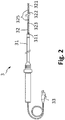
- FIG. 2 An exemplarily embodiment of the medical instrument 3 used for pressure measurement within the vessel is a guiding catheter-guidewire assembly, shown in Fig. 2 .
- the guiding catheter 31 is formed by a hollow handgrip and an elongated flexible tubular shaft comprising an inner lumen, and it is configured to movably receive the guidewire 32 formed by a flexible shaft.
- a pressure sensor 311 is integrated into the distal portion of the guiding catheter 31 for measurement of a blood pressure.
- the guidewire 32 also comprises at least a pressure sensor 321 integrated into its distal portion, for measurement of blood pressure at multiple locations along the blood vessel by using a pullback motion of the guidewire with respect to the blood vessel.
- Typical example for such guidewire is the Verrata® pressurewire, manufactured by Volcano Corporation.
- the guidewire 32 may comprise multiple sensors 321,322,323, distributed spatially along its distal portion, such that multiple pressure measurements along the vessel can be acquired in a stationary position of the guidewire with respect to the blood vessel, without the classical guidewire pullback being required.
- the instrument 3 may be formed as a catheter comprising a handgrip, an elongated flexible tubular shaft with an inner lumen configured to movably receive a telescopically extensible flexible shaft reaching distal to the tubular elongated shaft.
- the connection of the instrument 3 to the apparatus 2 is realized either by a connector 33 or a wireless connection.
- a pressure sensor 311 is integrated into the distal portion of the elongated tubular shaft, while at least one pressure sensor 321 is integrated into the distal portion of the telescopically extendable part of the medical instrument.
- the instrument 3 may comprise only the guidewire 32 with at least one integrated pressure sensor 321 into its distal region.
- the pressure sensors may employ one of the various techniques for blood pressure measurements, for instance the change of piezoresistive property upon pressure, fluidic transduction of a deflection of a diaphragm to a mechanical or an electrical signal, and capacitive readout of a suspended membrane over a substrate.
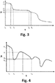
- Fig. 3 shows exemplarily a representation of the pressure measurement p along a vessel segment s.
- the instrument within the vessel provides a first pressure measurement signal p 1 at a first measurement location l 1 in the vessel and a second pressure measurement signal p 2 at a second measurement location l 2 .
- the resistance R is a function of the cross sectional area A of the vessel lumen.
- a more complex fluid dynamics model may be used.
- the corresponding inverse function can then be used to calculate the cross sectional area of the vessel lumen from a known resistance.
- the flow rate can be obtained by an additional intravascular measurement, or derived in any other suitable way.
- a volumetric flow rate as well as other related quantities e.g. flow velocity or average peak flow velocity can be used.
- the relative variation A(R(si)) / A(R(s 2 )) can be calculated without needing the flow rate as input.
- the measurement locations chosen in Fig. 3 are distant, in order to support the exemplary elucidation of the invention, however the measurement locations can be very close to each other, which can be achieved either by taking pressure measurements with the pressure wire having a slow pullback, or by making small incremental steps during the pullback motion.
- the cross sectional area A 1 is derived for the segment s 1 defined by the pressure measurement locations l 1 and l 2 .
- the reference positions r 1 to r 4 can be defined along the respective vessel segments s 1 to s 4 , and the cross sectional areas A 1 to A 4 can be assigned to the respective reference positions.
- the points (r 1 ,A 1 ) to (r 4 ,A 4 ) can be connected by using an appropriate interpolation function for providing a smooth transition of the cross sectional areas between the reference positions, resulting in a representation illustrated in Fig. 4 .
- the reference positions are located along the respective vessel segments, and they may be chosen as the middle of the segments, one of the measurement locations defining the respective segments, or they may be determined by using a function depending on the derived cross sectional area for the respective segment and that of the adjacent segment, for instance by using a weighted average.
- An intuitive illustration of the cross sectional areas in function of the respective reference positions along the blood vessel is a three-dimensional graphical representation 20 shown in figure Fig. 5 . In an embodiment shown in Fig.
- a further alternative representation may comprise the diameters at the respective reference positions, which can be derived from the respective cross sectional areas.
- the cross sectional areas and/or diameters can be derived for the entire length of the blood vessel defined by the locations of the first and last pressure measurements, based on the interpolation function.
- the instrument is configured to provide blood flow measurement besides the pressure measurements, hence the volumetric blood flow is calculated based on the blood flow measurement, which is then used in the calculation of the cross sectional areas A(s) and the diameters along the vessel.
- the system 1 in Fig. 1 may further comprise a tracking unit 72 for receiving temporal information about the location of the instrument 3 within the vasculature of the person 4.
- Spatial position tracking of the instrument may be based on one of an electromagnetic, an optical, an ultrasound, an electrical impedance and a radiological principle.
- Electromagnetic tracking of instruments is based on detection of an external electromagnetic field by electromagnetic sensors integrated into the instrument.
- the electromagnetic sensors, functioning as markers 325 in the electromagnetic field, are integrated into the distal portion of the instrument 3, for instance in the guiding catheter 31 and the guidewire 32, located at predetermined relative positions with respect to the pressure sensors 311 and 321, as shown in Fig. 2 .
- the electromagnetic field generator 71 may be removably attached to either the support means 5 of the person 4 or to the imaging unit 6.
- Multiple electromagnetic sensors integrated into the instrument 3 allow simultaneous localization of multiple points along the instrument 3, based on which the shape of a segment of the instrument 3 can be reconstructed by connecting the localized points.
- the tracking of the temporal location of the instrument is derived from laser radiation.
- the instrument comprises multiple optical fibers or a multi-core optical fiber extending from distal end to a proximal portion of the instrument 3, typically the handgrip, where optical connection to the tracking unit 72 is facilitated.
- the tracking unit 72 comprises a laser radiation generator configured to transmit laser radiation into at least an optical fiber integrated within the instrument, and an optical detector configured to receive reflections from within the at least one optical fiber.
- the shape of the at least one optical fiber, hence that of the instrument 3 is derived by processing optical reflection signals from within the optical fibers, received by a detector.
- the reflections of the laser radiation from within the at least one optical fiber are indicative of local strains to which the instrument 3 is exposed in tortuous vessel branches. Shape determination of a medical instrument based on optical shape sensing is described in details in WO 2008131303 A2 . Optical shape sensing makes possible the localization of any points along the at least one optical fiber integrated into the instrument 3 for all instances.
- the location tracking technique of the instrument is based on electrical impedance measurement.
- Electrical signals are sent into the patient by multiple electrically conductive patches distributed onto the body of the person 4.
- the distal portion of the trackable instrument 3 comprises spatially distributed electrically conductive electrodes, functioning as markers 325 for their relative positions with respect to the electrically conductive patches.
- the electrical impedances derived from the received electrical signals are indicative of the locations of the conductive electrodes in the region of interest comprising the target vasculature.
- the location of the instrument 3 is tracked by using the imaging unit.
- the instrument comprises specific markers 325 visible with the imaging modality used in the procedure.
- the instrument 3 comprises radiological markers along the distal portion of the instrument 3 at predetermined locations with respect to the pressure sensors 311 and 321, whereas for ultrasound imaging the instrument 3 comprises ultrasound sensors as markers 325, distributed spatially along the instrument.
- the generated ultrasound signal is transmitted into the body of the person 4 and a portion of the ultrasound signal is received by the ultrasound sensors integrated into the instrument 3.
- the time of flight of the ultrasound signals is indicative of the positions of the ultrasound sensors integrated into the instrument 3 with respect to the external ultrasound imaging unit, and by processing the signals the shape of the distal portion of the instrument comprising the ultrasound sensors can be reconstructed.
- the three-dimensional graphical representation 20 of the blood vessel can be improved by accounting for the bends encountered by the instrument along the vessel segment of interest, as illustrated in Fig. 7 .
- the bends of the vessel segment may also be represented in the two-dimensional projection 30, as shown in Fig. 8 .
- the blood flow in the vessel has a pulsatile nature, illustrated in Fig. 9 , and the cross sectional area of the vessel can be derived based on the pressure measurement signals averaged over a single cardiac cycle or over multiple cardiac cycles for the respective measurement locations.
- the cross sectional areas of the vessel are derived for subsequent phases I to VI of the pulsatile blood flow, and the representation of the vessel comprises a sequence of representations of the vessel corresponding to the subsequent phases of the pulsatile blood flow.
- the vessel may be displayed to the physician as a succession of frames of graphical representations rendered for the consecutive phases I to VI, or alternatively the physician may select particular phases of interest of the cardiac cycle for evaluation of potential conditions of the vessel where elasticity of the vessel segments may play a role, for instance in the evaluation of an asymmetric narrowing of the vessel and presence of an aneurysm.
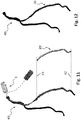
- the imaging unit 6 provides two-dimensional or three-dimensional morphological information of the vessel structure of interest upon injection of a contrast agent bolus in the targeted vasculature, and the morphology 40 of the vessel is rendered on the display 21, as shown in Fig. 10 .
- the shape of the instrument may be reconstructed and visualized as an overlay of the instrument 3 on the vessel morphology 40.
- Fig. 11 the instrument 3 is pulled back from a position 42 of its distal end to a position 43, while pressure measurement signals are acquired along the pullback length with the pressure sensor integrated into the distal region of the instrument.
- the position of the distal tip is continuously visualized by the imaging unit, therefore the trajectory of the tip can be reconstructed.
- the three-dimensional graphical representation 20 of the vessel model can be obtained by combination of the reconstructed trajectory of the distal tip of the instrument and the derived cross sectional areas of the vessel based on the pressure measurements along the pullback distance.
- the vessel model is presented separate from the vessel morphology to the physician, and the physician may use a user interface such as a touch screen or pointer means to superimpose the three-dimensional vessel model 20 onto the vessel morphology 40.
- a further alternative is the registration of the location information of the distal end or a portion of the distal region of the instrument comprising markers 325 during the pullback motion to the two-dimensional angiographic projection or to the three-dimensional angiographic representation.
- the two-dimensional projection 30 or the three-dimensional representation 20 of the vessel model can be gradually superimposed onto the vessel morphology 40 as the pressure measurements are processed and the cross sectional areas of the vessel are derived for the respective positions of the distal tip of the instrument, as shown in Fig. 12 .
- shape reconstruction of the instrument 3 based on optical shape sensing and by using multiple pressure sensors spatially distributed along the distal portion of the instrument, the two-dimensional projection 30 or the three-dimensional representation 20 of the vessel can be superimposed onto the vessel morphology 40 while the instrument is stationary with respect to the vessel, hence without requiring a pullback of the instrument.
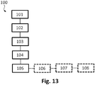
- a method 100 of characterizing a vessel of a living being comprising: receiving 101 from an instrument 3 within the vessel a first pressure measurement signal p 1 at a first measurement location l 1 and a second pressure measurement signal p 2 at a second measurement location l 2 ; and deriving 102 a first cross sectional area A 1 for a first reference position r 1 of the vessel based on the first and second pressure measurement signals p 1 ,p 2 .
- the method further comprises: receiving 103 from the instrument within the vessel a third pressure measurement signal p 3 at a third measurement location l 3 ; deriving 104 a second cross sectional area A 2 for a second reference position r 2 of the vessel based on the third pressure measurement signal p 3 and one of the first and second pressure measurement signals p 1 ,p 2 ; and rendering 105 a representation of the vessel based on the first and second cross sectional areas A 1 ,A 2 and the first and second reference positions r 1 ,r 2 .
- the method may further comprise: receiving 106 morphological information of the vessel from an imaging unit 6; rendering 107 a morphological representation 40 of the vessel based on the morphological information; and composing 108 the morphological representation 40 of the vessel with either the three-dimensional vessel model 20 or the two-dimensional projection 30 of the vessel model rendered based on the first and second cross sectional areas A 1 ,A 2 , and the first and second reference positions r 1 ,r 2 .
- cross sectional area of the vessel is derived from the pressure measurement signals in the exemplary description, it can be understood and effected by those skilled in the art in practicing the claimed invention that a diameter, a radius or a perimeter can be derived from the cross sectional area of the vessel by simple mathematical formulas.
- a single unit or device may fulfill the functions of several items recited in the claims.
- the mere fact that certain measures are recited in mutually different dependent claims does not indicate that a combination of these measures cannot be used to advantage.
Landscapes
- Health & Medical Sciences (AREA)
- Life Sciences & Earth Sciences (AREA)
- Engineering & Computer Science (AREA)
- General Health & Medical Sciences (AREA)
- Medical Informatics (AREA)
- Physics & Mathematics (AREA)
- Animal Behavior & Ethology (AREA)
- Pathology (AREA)
- Biophysics (AREA)
- Biomedical Technology (AREA)
- Heart & Thoracic Surgery (AREA)
- Molecular Biology (AREA)
- Surgery (AREA)
- Public Health (AREA)
- Veterinary Medicine (AREA)
- Cardiology (AREA)
- Physiology (AREA)
- Nuclear Medicine, Radiotherapy & Molecular Imaging (AREA)
- Vascular Medicine (AREA)
- Radiology & Medical Imaging (AREA)
- Human Computer Interaction (AREA)
- Dentistry (AREA)
- Oral & Maxillofacial Surgery (AREA)
- Quality & Reliability (AREA)
- Computer Vision & Pattern Recognition (AREA)
- General Physics & Mathematics (AREA)
- Theoretical Computer Science (AREA)
- Measuring Pulse, Heart Rate, Blood Pressure Or Blood Flow (AREA)
- Ultra Sonic Daignosis Equipment (AREA)
- Apparatus For Radiation Diagnosis (AREA)
- Magnetic Resonance Imaging Apparatus (AREA)
Claims (8)
- Vorrichtung (2) zur Charakterisierung eines Blutgefäßes eines Lebewesens (4), wobei die Vorrichtung einen Prozessor umfasst, der konfiguriert ist, um:von einem Instrument (3) innerhalb des Blutgefäßes ein erstes zeitliches Druckmesssignal (p1) an einer ersten Messstelle (l1), ein zweites zeitliches Druckmesssignal (p2) an einer zweiten Messstelle (l2) und ein drittes zeitliches Druckmesssignal (p3) an einer dritten Messstelle (l3) eines pulsierenden Blutflusses innerhalb des Blutgefäßes zu empfangen;einen ersten Querschnittsbereich (A1) für eine erste Referenzposition (r1) des Blutgefäßes basierend auf dem ersten und zweiten Druckmesssignal (p1,p2) abzuleiten; undeine zweite Querschnittsfläche (A2) für eine zweite Referenzposition (r2) des Blutgefäßes basierend auf dem dritten Druckmesssignal (p3) und einem der ersten und zweiten Druckmesssignale (p1,p2) abzuleiten, wobei die ersten und zweiten Querschnittsflächen (A1,A2) für nachfolgende Phasen (I-VI) des pulsierenden Blutflusses abgeleitet sind;dadurch gekennzeichnet, dass der Prozessor weiter konfiguriert ist, um:
eine Darstellung des Blutgefäßes (20, 30) basierend auf den ersten und zweiten Querschnittsflächen (A1,A2) und den ersten und zweiten Referenzpositionen (r1,r2) zu rendern, wobei die Darstellung des Blutgefäßes eine Folge von Darstellungen (20, 30) des Blutgefäßes umfasst, die den nachfolgenden Phasen (I-VI) des pulsierenden Blutflusses entspricht. - Vorrichtung (2) nach Anspruch 1, wobei der Prozessor weiter konfiguriert ist, um:morphologische Informationen des Blutgefäßes von einer bildgebenden Einheit (6) zu empfangen;
eine zusammengesetzte Darstellung zu rendern, umfassend:
eine morphologische Darstellung (40) des Blutgefäßes basierend auf den morphologischen Informationen; unddie Darstellung (20, 30) des Blutgefäßes basierend auf den ersten und zweiten Querschnittsflächen (A1, A2) und der ersten und zweiten Referenzposition (r1, r2). - Vorrichtung (2) nach Anspruch 1, wobei der Prozessor weiter konfiguriert ist, um die erste, zweite und dritte Messstelle (l1, l2, l3) basierend auf Informationen zu bestimmen, die von einer Verfolgungseinheit (72) auf der Position mindestens einer Markerkomponente (325) des Instruments (3) bereitgestellt werden.
- System (1) zur Charakterisierung eines Blutgefäßes eines Lebewesens (4), umfassend:die Vorrichtung (2) nach Anspruch 1;wobei das Instrument (3) mindestens einen Drucksensor (321) umfasst, der konfiguriert ist, um das erste, zweite und dritte Druckmesssignal (p1,p2,p3) an der ersten, zweiten und dritten Messstelle (l1, l2,l3) innerhalb des Blutgefäßes bereitzustellen.
- System (1) nach Anspruch 4, wobei:der mindestens eine Drucksensor (321) das erste Druckmesssignal (p1) an der ersten Messstelle (l1) bereitstellt,das Instrument (3) einen zweiten und einen dritten Drucksensor (322, 323) zum Bereitstellen des zweiten und dritten Druckmesssignals (p2,p3) an der zweiten beziehungsweise dritten Messstelle (l2,l3) umfasst.
- System (1) nach Anspruch 4, wobei:
das Instrument konfiguriert ist, um das erste, zweite und dritte Druckmesssignal (p1,p2,p3) durch nachfolgende Änderungen einer Position des mindestens einen Drucksensors (321) entlang des Blutgefäßes bereitzustellen. - System (1) nach einem der Ansprüche 4 bis 6, wobei der Prozessor ferner konfiguriert ist, um:morphologische Informationen des Blutgefäßes von einer bildgebenden Einheit (6) zu empfangen;eine zusammengesetzte Darstellung zu rendern, umfassend:eine morphologische Darstellung (40) des Blutgefäßes basierend auf den morphologischen Informationen; unddie Darstellung (20, 30) des Blutgefäßes basierend auf den ersten und zweiten Querschnittsflächen (A1, A2) und der ersten und zweiten Referenzposition (r1, r2).
- System (1) nach Anspruch 7, umfassend die bildgebende Einheit (6), wobei der Prozessor weiter konfiguriert ist, um:um die erste, zweite und dritte Messstelle (l1, l2, l3) basierend auf dem Erfassen mindestens einer Markerkomponente (325) des Instruments (3) durch die bildgebende Einheit zu bestimmen;die erste, zweite und dritte Messstelle (l1,l2, l3) mit der morphologischen Darstellung (40) des Blutgefäßes aufzuzeichnen.
Applications Claiming Priority (2)
| Application Number | Priority Date | Filing Date | Title |
|---|---|---|---|
| EP16158610 | 2016-03-04 | ||
| PCT/EP2017/054539 WO2017148877A1 (en) | 2016-03-04 | 2017-02-28 | Apparatus for vessel characterization |
Publications (2)
| Publication Number | Publication Date |
|---|---|
| EP3422929A1 EP3422929A1 (de) | 2019-01-09 |
| EP3422929B1 true EP3422929B1 (de) | 2019-09-11 |
Family
ID=55586134
Family Applications (1)
| Application Number | Title | Priority Date | Filing Date |
|---|---|---|---|
| EP17706827.7A Active EP3422929B1 (de) | 2016-03-04 | 2017-02-28 | Vorrichtung zur gefässcharakterisierung |
Country Status (5)
| Country | Link |
|---|---|
| US (2) | US10694955B2 (de) |
| EP (1) | EP3422929B1 (de) |
| JP (1) | JP6521476B2 (de) |
| CN (1) | CN108778107B (de) |
| WO (1) | WO2017148877A1 (de) |
Families Citing this family (15)
| Publication number | Priority date | Publication date | Assignee | Title |
|---|---|---|---|---|
| US12465324B2 (en) | 2015-02-12 | 2025-11-11 | Foundry Innovation & Research 1, Ltd. | Patient fluid management systems and methods employing integrated fluid status sensing |
| DE202016008639U1 (de) | 2015-02-12 | 2019-01-16 | Foundry Innovation & Research 1, Ltd. | Implantierbare Vorrichtungen zur Überwachung der Herzinsuffizienz |
| WO2018031714A1 (en) | 2016-08-11 | 2018-02-15 | Foundry Innovation & Research 1, Ltd. | Systems and methods for patient fluid management |
| EP3331426B1 (de) | 2015-08-03 | 2024-07-24 | Foundry Innovation&Research 1, Ltd. | Katheter zur messung von abmessung der vena cava |
| US11206992B2 (en) | 2016-08-11 | 2021-12-28 | Foundry Innovation & Research 1, Ltd. | Wireless resonant circuit and variable inductance vascular monitoring implants and anchoring structures therefore |
| US11701018B2 (en) | 2016-08-11 | 2023-07-18 | Foundry Innovation & Research 1, Ltd. | Wireless resonant circuit and variable inductance vascular monitoring implants and anchoring structures therefore |
| EP3463082B1 (de) | 2016-11-29 | 2020-07-29 | Foundry Innovation & Research 1, Ltd. | Gefässimplantate mit drahtlosem resonanzkreis und variabler induktivität zur überwachung des gefässsystems |
| WO2018220143A1 (en) | 2017-05-31 | 2018-12-06 | Foundry Innovation And Research 1, Ltd | Implantable ultrasonic vascular sensor |
| WO2018220146A1 (en) | 2017-05-31 | 2018-12-06 | Foundry Innovation & Research 1, Ltd. | Implantable sensors for vascular monitoring |
| JP7649237B2 (ja) * | 2018-10-26 | 2025-03-19 | コーニンクレッカ フィリップス エヌ ヴェ | 脈波伝播速度測定システム |
| USD926199S1 (en) | 2019-05-17 | 2021-07-27 | Opsens, Inc. | Display screen or portion thereof with graphical user interface |
| EP3968851B1 (de) | 2019-05-17 | 2025-10-22 | Opsens Inc. | Druckbasierte strukturelle herzbewertungssysteme |
| CN111436910B (zh) * | 2020-04-28 | 2023-07-18 | 北京信息科技大学 | 一种活体组织的光学相干层析多模态成像装置及方法 |
| US12465233B2 (en) | 2022-07-29 | 2025-11-11 | Foundry Innovation & Research 1, Ltd. | Multistranded conductors adapted to dynamic in vivo environments |
| US20240350016A1 (en) * | 2023-04-18 | 2024-10-24 | Bard Access Systems, Inc. | System and Method for Placement of a Central Catheter Tip |
Family Cites Families (23)
| Publication number | Priority date | Publication date | Assignee | Title |
|---|---|---|---|---|
| DE3714027A1 (de) | 1987-04-27 | 1988-11-10 | Alt Eckhard | Katheter und geraet zum anschluss an einen katheter |
| WO2001013779A2 (en) * | 1999-08-25 | 2001-03-01 | Florence Medical Ltd. | A method and system for stenosis identification, localization and characterization using pressure measurements |
| US6354999B1 (en) * | 2000-01-14 | 2002-03-12 | Florence Medical Ltd. | System and method for detecting, localizing, and characterizing occlusions and aneurysms in a vessel |
| JP2005512777A (ja) | 2001-12-21 | 2005-05-12 | コーニンクレッカ フィリップス エレクトロニクス エヌ ヴィ | 髪の毛の根元に添加剤を塗布する装置 |
| EP1585441A4 (de) | 2003-01-24 | 2008-05-21 | Proteus Biomedical Inc | Verfahren und systeme zur messung von herzparametern |
| WO2004075928A2 (en) * | 2003-02-21 | 2004-09-10 | Electro-Cat, Llc | System and method for measuring cross-sectional areas and pressure gradients in luminal organs |
| US8050523B2 (en) | 2007-04-20 | 2011-11-01 | Koninklijke Philips Electronics N.V. | Optical fiber shape sensing systems |
| CN102046069A (zh) * | 2008-05-12 | 2011-05-04 | 心脏技术有限公司 | 用于监视健康状况的方法和系统 |
| CN101278828A (zh) * | 2008-05-20 | 2008-10-08 | 上海大学 | 测量心室壁微面积功的方法 |
| US8315812B2 (en) | 2010-08-12 | 2012-11-20 | Heartflow, Inc. | Method and system for patient-specific modeling of blood flow |
| JP6092124B2 (ja) * | 2011-02-07 | 2017-03-08 | コーニンクレッカ フィリップス エヌ ヴェKoninklijke Philips N.V. | 血管介入手順において介入装置の正確な位置決めを支援する画像描写を提供する医用撮像装置 |
| US9107639B2 (en) | 2011-03-15 | 2015-08-18 | Medicinsk Bildteknik Sverige Ab | System for synchronously visualizing a representation of first and second input data |
| EP2717759A4 (de) * | 2011-06-13 | 2014-12-10 | Angiometrix Corp | Multifunktionelle führungsdrahtanordnungen und system zur analyse anatomischer und funktions-parameter |
| WO2013055896A1 (en) * | 2011-10-14 | 2013-04-18 | Acist Medical Systems, Inc. | Device and methods for measuring and treating an anatomical structure |
| US20140243688A1 (en) * | 2011-10-28 | 2014-08-28 | Three Rivers Cardiovascular Systems Inc. | Fluid temperature and flow sensor apparatus and system for cardiovascular and other medical applications |
| US9549679B2 (en) * | 2012-05-14 | 2017-01-24 | Acist Medical Systems, Inc. | Multiple transducer delivery device and method |
| EP3903672B1 (de) * | 2012-08-03 | 2023-11-01 | Philips Image Guided Therapy Corporation | Vorrichtungen, systeme und verfahren zur beurteilung eines gefässes |
| JP6445982B2 (ja) * | 2012-12-31 | 2018-12-26 | ボルケーノ コーポレイション | 管の評価のための装置、システム、及び方法 |
| CN103330566B (zh) * | 2013-06-21 | 2015-04-08 | 汉斯·葛根森 | 测量和分析身体中空腔器官的轨迹和角度的装置 |
| JP6782634B2 (ja) | 2013-10-25 | 2020-11-11 | ボルケーノ コーポレイション | 患者の血管を評価する際の支援のために前記血管の情報を提供するためのシステム |
| EP3136966B1 (de) * | 2014-05-02 | 2019-01-23 | Koninklijke Philips N.V. | Vorrichtung zur bewertung von intravaskulärem druck |
| CN106659394A (zh) * | 2014-07-13 | 2017-05-10 | 三河城心血管系统有限公司 | 用于介入性心脏病学的包括多传感器导丝的系统和装置 |
| CN104739377B (zh) * | 2015-03-20 | 2018-01-23 | 武汉阿格斯科技有限公司 | 血管内同时进行oct成像和压力测量装置、系统及方法 |
-
2017
- 2017-02-28 WO PCT/EP2017/054539 patent/WO2017148877A1/en not_active Ceased
- 2017-02-28 EP EP17706827.7A patent/EP3422929B1/de active Active
- 2017-02-28 JP JP2018545463A patent/JP6521476B2/ja not_active Expired - Fee Related
- 2017-02-28 CN CN201780015125.3A patent/CN108778107B/zh not_active Expired - Fee Related
- 2017-02-28 US US16/080,243 patent/US10694955B2/en not_active Expired - Fee Related
-
2020
- 2020-06-29 US US16/915,151 patent/US20200329980A1/en not_active Abandoned
Non-Patent Citations (1)
| Title |
|---|
| None * |
Also Published As
| Publication number | Publication date |
|---|---|
| JP2019506258A (ja) | 2019-03-07 |
| JP6521476B2 (ja) | 2019-05-29 |
| EP3422929A1 (de) | 2019-01-09 |
| WO2017148877A1 (en) | 2017-09-08 |
| CN108778107B (zh) | 2021-08-03 |
| US20190046047A1 (en) | 2019-02-14 |
| US20200329980A1 (en) | 2020-10-22 |
| CN108778107A (zh) | 2018-11-09 |
| US10694955B2 (en) | 2020-06-30 |
Similar Documents
| Publication | Publication Date | Title |
|---|---|---|
| US10694955B2 (en) | Apparatus for vessel characterization | |
| US20240065640A1 (en) | Interactive cardiac test data and associated devices, systems, and methods | |
| US20250134474A1 (en) | Percutaneous coronary intervention (pci) planning interface with pressure data and vessel data and associated devices, systems, and methods | |
| EP2938271B1 (de) | Vorrichtungen, systeme und verfahren zur beurteilung von gefässen | |
| US11839457B2 (en) | Measurement guidance for coronary flow estimation from Bernoulli's Principle | |
| JP6938469B2 (ja) | 血管を特徴付ける装置 | |
| CN108471963A (zh) | 用于基于期望的结果的冠状动脉介入评估、规划和处置的设备、系统以及方法 | |
| US20160157808A1 (en) | Interactive physiologic data and intravascular imaging data and associated devices, systems and methods | |
| WO2019053030A1 (en) | ESTIMATION OF FLOW TO SHIP BIFURCATIONS FOR SIMULATED HEMODYNAMICS | |
| US11918325B2 (en) | Pulse wave velocity measurement system | |
| EP3456243A1 (de) | Verbesserte gefässgeometrie und zusätzliche randbedingungen für hämodynamische ffr-/ifr-simulationen aus intravaskulärer bildgebung | |
| US11864869B2 (en) | Apparatus for characterizing a vessel wall | |
| EP3714780A1 (de) | System zur messung der pulswellengeschwindigkeit | |
| Ruijters | Apparatus for characterizing a vessel wall |
Legal Events
| Date | Code | Title | Description |
|---|---|---|---|
| STAA | Information on the status of an ep patent application or granted ep patent |
Free format text: STATUS: UNKNOWN |
|
| STAA | Information on the status of an ep patent application or granted ep patent |
Free format text: STATUS: THE INTERNATIONAL PUBLICATION HAS BEEN MADE |
|
| PUAI | Public reference made under article 153(3) epc to a published international application that has entered the european phase |
Free format text: ORIGINAL CODE: 0009012 |
|
| STAA | Information on the status of an ep patent application or granted ep patent |
Free format text: STATUS: REQUEST FOR EXAMINATION WAS MADE |
|
| 17P | Request for examination filed |
Effective date: 20181004 |
|
| AK | Designated contracting states |
Kind code of ref document: A1 Designated state(s): AL AT BE BG CH CY CZ DE DK EE ES FI FR GB GR HR HU IE IS IT LI LT LU LV MC MK MT NL NO PL PT RO RS SE SI SK SM TR |
|
| AX | Request for extension of the european patent |
Extension state: BA ME |
|
| GRAP | Despatch of communication of intention to grant a patent |
Free format text: ORIGINAL CODE: EPIDOSNIGR1 |
|
| STAA | Information on the status of an ep patent application or granted ep patent |
Free format text: STATUS: GRANT OF PATENT IS INTENDED |
|
| DAV | Request for validation of the european patent (deleted) | ||
| DAX | Request for extension of the european patent (deleted) | ||
| INTG | Intention to grant announced |
Effective date: 20190408 |
|
| GRAS | Grant fee paid |
Free format text: ORIGINAL CODE: EPIDOSNIGR3 |
|
| GRAA | (expected) grant |
Free format text: ORIGINAL CODE: 0009210 |
|
| STAA | Information on the status of an ep patent application or granted ep patent |
Free format text: STATUS: THE PATENT HAS BEEN GRANTED |
|
| AK | Designated contracting states |
Kind code of ref document: B1 Designated state(s): AL AT BE BG CH CY CZ DE DK EE ES FI FR GB GR HR HU IE IS IT LI LT LU LV MC MK MT NL NO PL PT RO RS SE SI SK SM TR |
|
| REG | Reference to a national code |
Ref country code: GB Ref legal event code: FG4D |
|
| REG | Reference to a national code |
Ref country code: CH Ref legal event code: EP |
|
| REG | Reference to a national code |
Ref country code: AT Ref legal event code: REF Ref document number: 1177429 Country of ref document: AT Kind code of ref document: T Effective date: 20190915 |
|
| REG | Reference to a national code |
Ref country code: DE Ref legal event code: R096 Ref document number: 602017007000 Country of ref document: DE Ref country code: IE Ref legal event code: FG4D |
|
| REG | Reference to a national code |
Ref country code: NL Ref legal event code: MP Effective date: 20190911 |
|
| REG | Reference to a national code |
Ref country code: LT Ref legal event code: MG4D |
|
| PG25 | Lapsed in a contracting state [announced via postgrant information from national office to epo] |
Ref country code: HR Free format text: LAPSE BECAUSE OF FAILURE TO SUBMIT A TRANSLATION OF THE DESCRIPTION OR TO PAY THE FEE WITHIN THE PRESCRIBED TIME-LIMIT Effective date: 20190911 Ref country code: LT Free format text: LAPSE BECAUSE OF FAILURE TO SUBMIT A TRANSLATION OF THE DESCRIPTION OR TO PAY THE FEE WITHIN THE PRESCRIBED TIME-LIMIT Effective date: 20190911 Ref country code: SE Free format text: LAPSE BECAUSE OF FAILURE TO SUBMIT A TRANSLATION OF THE DESCRIPTION OR TO PAY THE FEE WITHIN THE PRESCRIBED TIME-LIMIT Effective date: 20190911 Ref country code: BG Free format text: LAPSE BECAUSE OF FAILURE TO SUBMIT A TRANSLATION OF THE DESCRIPTION OR TO PAY THE FEE WITHIN THE PRESCRIBED TIME-LIMIT Effective date: 20191211 Ref country code: FI Free format text: LAPSE BECAUSE OF FAILURE TO SUBMIT A TRANSLATION OF THE DESCRIPTION OR TO PAY THE FEE WITHIN THE PRESCRIBED TIME-LIMIT Effective date: 20190911 Ref country code: NO Free format text: LAPSE BECAUSE OF FAILURE TO SUBMIT A TRANSLATION OF THE DESCRIPTION OR TO PAY THE FEE WITHIN THE PRESCRIBED TIME-LIMIT Effective date: 20191211 |
|
| PG25 | Lapsed in a contracting state [announced via postgrant information from national office to epo] |
Ref country code: RS Free format text: LAPSE BECAUSE OF FAILURE TO SUBMIT A TRANSLATION OF THE DESCRIPTION OR TO PAY THE FEE WITHIN THE PRESCRIBED TIME-LIMIT Effective date: 20190911 Ref country code: LV Free format text: LAPSE BECAUSE OF FAILURE TO SUBMIT A TRANSLATION OF THE DESCRIPTION OR TO PAY THE FEE WITHIN THE PRESCRIBED TIME-LIMIT Effective date: 20190911 Ref country code: AL Free format text: LAPSE BECAUSE OF FAILURE TO SUBMIT A TRANSLATION OF THE DESCRIPTION OR TO PAY THE FEE WITHIN THE PRESCRIBED TIME-LIMIT Effective date: 20190911 Ref country code: GR Free format text: LAPSE BECAUSE OF FAILURE TO SUBMIT A TRANSLATION OF THE DESCRIPTION OR TO PAY THE FEE WITHIN THE PRESCRIBED TIME-LIMIT Effective date: 20191212 Ref country code: ES Free format text: LAPSE BECAUSE OF FAILURE TO SUBMIT A TRANSLATION OF THE DESCRIPTION OR TO PAY THE FEE WITHIN THE PRESCRIBED TIME-LIMIT Effective date: 20190911 |
|
| RAP2 | Party data changed (patent owner data changed or rights of a patent transferred) |
Owner name: KONINKLIJKE PHILIPS N.V. |
|
| REG | Reference to a national code |
Ref country code: AT Ref legal event code: MK05 Ref document number: 1177429 Country of ref document: AT Kind code of ref document: T Effective date: 20190911 |
|
| PG25 | Lapsed in a contracting state [announced via postgrant information from national office to epo] |
Ref country code: AT Free format text: LAPSE BECAUSE OF FAILURE TO SUBMIT A TRANSLATION OF THE DESCRIPTION OR TO PAY THE FEE WITHIN THE PRESCRIBED TIME-LIMIT Effective date: 20190911 Ref country code: PT Free format text: LAPSE BECAUSE OF FAILURE TO SUBMIT A TRANSLATION OF THE DESCRIPTION OR TO PAY THE FEE WITHIN THE PRESCRIBED TIME-LIMIT Effective date: 20200113 Ref country code: PL Free format text: LAPSE BECAUSE OF FAILURE TO SUBMIT A TRANSLATION OF THE DESCRIPTION OR TO PAY THE FEE WITHIN THE PRESCRIBED TIME-LIMIT Effective date: 20190911 Ref country code: IT Free format text: LAPSE BECAUSE OF FAILURE TO SUBMIT A TRANSLATION OF THE DESCRIPTION OR TO PAY THE FEE WITHIN THE PRESCRIBED TIME-LIMIT Effective date: 20190911 Ref country code: EE Free format text: LAPSE BECAUSE OF FAILURE TO SUBMIT A TRANSLATION OF THE DESCRIPTION OR TO PAY THE FEE WITHIN THE PRESCRIBED TIME-LIMIT Effective date: 20190911 Ref country code: NL Free format text: LAPSE BECAUSE OF FAILURE TO SUBMIT A TRANSLATION OF THE DESCRIPTION OR TO PAY THE FEE WITHIN THE PRESCRIBED TIME-LIMIT Effective date: 20190911 Ref country code: RO Free format text: LAPSE BECAUSE OF FAILURE TO SUBMIT A TRANSLATION OF THE DESCRIPTION OR TO PAY THE FEE WITHIN THE PRESCRIBED TIME-LIMIT Effective date: 20190911 |
|
| PG25 | Lapsed in a contracting state [announced via postgrant information from national office to epo] |
Ref country code: SM Free format text: LAPSE BECAUSE OF FAILURE TO SUBMIT A TRANSLATION OF THE DESCRIPTION OR TO PAY THE FEE WITHIN THE PRESCRIBED TIME-LIMIT Effective date: 20190911 Ref country code: CZ Free format text: LAPSE BECAUSE OF FAILURE TO SUBMIT A TRANSLATION OF THE DESCRIPTION OR TO PAY THE FEE WITHIN THE PRESCRIBED TIME-LIMIT Effective date: 20190911 Ref country code: IS Free format text: LAPSE BECAUSE OF FAILURE TO SUBMIT A TRANSLATION OF THE DESCRIPTION OR TO PAY THE FEE WITHIN THE PRESCRIBED TIME-LIMIT Effective date: 20200224 Ref country code: SK Free format text: LAPSE BECAUSE OF FAILURE TO SUBMIT A TRANSLATION OF THE DESCRIPTION OR TO PAY THE FEE WITHIN THE PRESCRIBED TIME-LIMIT Effective date: 20190911 |
|
| REG | Reference to a national code |
Ref country code: DE Ref legal event code: R097 Ref document number: 602017007000 Country of ref document: DE |
|
| PLBE | No opposition filed within time limit |
Free format text: ORIGINAL CODE: 0009261 |
|
| STAA | Information on the status of an ep patent application or granted ep patent |
Free format text: STATUS: NO OPPOSITION FILED WITHIN TIME LIMIT |
|
| PG2D | Information on lapse in contracting state deleted |
Ref country code: IS |
|
| PG25 | Lapsed in a contracting state [announced via postgrant information from national office to epo] |
Ref country code: DK Free format text: LAPSE BECAUSE OF FAILURE TO SUBMIT A TRANSLATION OF THE DESCRIPTION OR TO PAY THE FEE WITHIN THE PRESCRIBED TIME-LIMIT Effective date: 20190911 Ref country code: IS Free format text: LAPSE BECAUSE OF FAILURE TO SUBMIT A TRANSLATION OF THE DESCRIPTION OR TO PAY THE FEE WITHIN THE PRESCRIBED TIME-LIMIT Effective date: 20200112 |
|
| 26N | No opposition filed |
Effective date: 20200615 |
|
| REG | Reference to a national code |
Ref country code: CH Ref legal event code: PL |
|
| REG | Reference to a national code |
Ref country code: BE Ref legal event code: MM Effective date: 20200229 |
|
| PG25 | Lapsed in a contracting state [announced via postgrant information from national office to epo] |
Ref country code: MC Free format text: LAPSE BECAUSE OF FAILURE TO SUBMIT A TRANSLATION OF THE DESCRIPTION OR TO PAY THE FEE WITHIN THE PRESCRIBED TIME-LIMIT Effective date: 20190911 Ref country code: LU Free format text: LAPSE BECAUSE OF NON-PAYMENT OF DUE FEES Effective date: 20200228 |
|
| PG25 | Lapsed in a contracting state [announced via postgrant information from national office to epo] |
Ref country code: CH Free format text: LAPSE BECAUSE OF NON-PAYMENT OF DUE FEES Effective date: 20200229 Ref country code: LI Free format text: LAPSE BECAUSE OF NON-PAYMENT OF DUE FEES Effective date: 20200229 |
|
| PG25 | Lapsed in a contracting state [announced via postgrant information from national office to epo] |
Ref country code: IE Free format text: LAPSE BECAUSE OF NON-PAYMENT OF DUE FEES Effective date: 20200228 |
|
| PG25 | Lapsed in a contracting state [announced via postgrant information from national office to epo] |
Ref country code: BE Free format text: LAPSE BECAUSE OF NON-PAYMENT OF DUE FEES Effective date: 20200229 |
|
| PGFP | Annual fee paid to national office [announced via postgrant information from national office to epo] |
Ref country code: FR Payment date: 20210223 Year of fee payment: 5 |
|
| PGFP | Annual fee paid to national office [announced via postgrant information from national office to epo] |
Ref country code: GB Payment date: 20210223 Year of fee payment: 5 Ref country code: DE Payment date: 20210225 Year of fee payment: 5 |
|
| PG25 | Lapsed in a contracting state [announced via postgrant information from national office to epo] |
Ref country code: TR Free format text: LAPSE BECAUSE OF FAILURE TO SUBMIT A TRANSLATION OF THE DESCRIPTION OR TO PAY THE FEE WITHIN THE PRESCRIBED TIME-LIMIT Effective date: 20190911 Ref country code: MT Free format text: LAPSE BECAUSE OF FAILURE TO SUBMIT A TRANSLATION OF THE DESCRIPTION OR TO PAY THE FEE WITHIN THE PRESCRIBED TIME-LIMIT Effective date: 20190911 Ref country code: CY Free format text: LAPSE BECAUSE OF FAILURE TO SUBMIT A TRANSLATION OF THE DESCRIPTION OR TO PAY THE FEE WITHIN THE PRESCRIBED TIME-LIMIT Effective date: 20190911 |
|
| PG25 | Lapsed in a contracting state [announced via postgrant information from national office to epo] |
Ref country code: MK Free format text: LAPSE BECAUSE OF FAILURE TO SUBMIT A TRANSLATION OF THE DESCRIPTION OR TO PAY THE FEE WITHIN THE PRESCRIBED TIME-LIMIT Effective date: 20190911 |
|
| REG | Reference to a national code |
Ref country code: DE Ref legal event code: R119 Ref document number: 602017007000 Country of ref document: DE |
|
| GBPC | Gb: european patent ceased through non-payment of renewal fee |
Effective date: 20220228 |
|
| PG25 | Lapsed in a contracting state [announced via postgrant information from national office to epo] |
Ref country code: FR Free format text: LAPSE BECAUSE OF NON-PAYMENT OF DUE FEES Effective date: 20220228 |
|
| PG25 | Lapsed in a contracting state [announced via postgrant information from national office to epo] |
Ref country code: GB Free format text: LAPSE BECAUSE OF NON-PAYMENT OF DUE FEES Effective date: 20220228 Ref country code: DE Free format text: LAPSE BECAUSE OF NON-PAYMENT OF DUE FEES Effective date: 20220901 |
|
| PG25 | Lapsed in a contracting state [announced via postgrant information from national office to epo] |
Ref country code: SI Free format text: LAPSE BECAUSE OF FAILURE TO SUBMIT A TRANSLATION OF THE DESCRIPTION OR TO PAY THE FEE WITHIN THE PRESCRIBED TIME-LIMIT Effective date: 20190911 |