EP3423167B1 - Élément de filtre destiné à un véhicule - Google Patents
Élément de filtre destiné à un véhicule Download PDFInfo
- Publication number
- EP3423167B1 EP3423167B1 EP16715609.0A EP16715609A EP3423167B1 EP 3423167 B1 EP3423167 B1 EP 3423167B1 EP 16715609 A EP16715609 A EP 16715609A EP 3423167 B1 EP3423167 B1 EP 3423167B1
- Authority
- EP
- European Patent Office
- Prior art keywords
- filter element
- detachable plug
- filter
- axial
- channel
- Prior art date
- Legal status (The legal status is an assumption and is not a legal conclusion. Google has not performed a legal analysis and makes no representation as to the accuracy of the status listed.)
- Active
Links
Images


Classifications
-
- B—PERFORMING OPERATIONS; TRANSPORTING
- B01—PHYSICAL OR CHEMICAL PROCESSES OR APPARATUS IN GENERAL
- B01D—SEPARATION
- B01D35/00—Filtering devices having features not specifically covered by groups B01D24/00 - B01D33/00, or for applications not specifically covered by groups B01D24/00 - B01D33/00; Auxiliary devices for filtration; Filter housing constructions
- B01D35/14—Safety devices specially adapted for filtration; Devices for indicating clogging
- B01D35/153—Anti-leakage or anti-return valves
-
- B—PERFORMING OPERATIONS; TRANSPORTING
- B01—PHYSICAL OR CHEMICAL PROCESSES OR APPARATUS IN GENERAL
- B01D—SEPARATION
- B01D29/00—Filters with filtering elements stationary during filtration, e.g. pressure or suction filters, not covered by groups B01D24/00 - B01D27/00; Filtering elements therefor
- B01D29/11—Filters with filtering elements stationary during filtration, e.g. pressure or suction filters, not covered by groups B01D24/00 - B01D27/00; Filtering elements therefor with bag, cage, hose, tube, sleeve or like filtering elements
- B01D29/13—Supported filter elements
- B01D29/15—Supported filter elements arranged for inward flow filtration
- B01D29/21—Supported filter elements arranged for inward flow filtration with corrugated, folded or wound sheets
-
- B—PERFORMING OPERATIONS; TRANSPORTING
- B01—PHYSICAL OR CHEMICAL PROCESSES OR APPARATUS IN GENERAL
- B01D—SEPARATION
- B01D29/00—Filters with filtering elements stationary during filtration, e.g. pressure or suction filters, not covered by groups B01D24/00 - B01D27/00; Filtering elements therefor
- B01D29/96—Filters with filtering elements stationary during filtration, e.g. pressure or suction filters, not covered by groups B01D24/00 - B01D27/00; Filtering elements therefor in which the filtering elements are moved between filtering operations; Particular measures for removing or replacing the filtering elements; Transport systems for filters
-
- B—PERFORMING OPERATIONS; TRANSPORTING
- B01—PHYSICAL OR CHEMICAL PROCESSES OR APPARATUS IN GENERAL
- B01D—SEPARATION
- B01D35/00—Filtering devices having features not specifically covered by groups B01D24/00 - B01D33/00, or for applications not specifically covered by groups B01D24/00 - B01D33/00; Auxiliary devices for filtration; Filter housing constructions
- B01D35/005—Filters specially adapted for use in internal-combustion engine lubrication or fuel systems
-
- B—PERFORMING OPERATIONS; TRANSPORTING
- B01—PHYSICAL OR CHEMICAL PROCESSES OR APPARATUS IN GENERAL
- B01D—SEPARATION
- B01D2201/00—Details relating to filtering apparatus
- B01D2201/04—Supports for the filtering elements
- B01D2201/0415—Details of supporting structures
-
- B—PERFORMING OPERATIONS; TRANSPORTING
- B01—PHYSICAL OR CHEMICAL PROCESSES OR APPARATUS IN GENERAL
- B01D—SEPARATION
- B01D2201/00—Details relating to filtering apparatus
- B01D2201/29—Filter cartridge constructions
- B01D2201/291—End caps
-
- B—PERFORMING OPERATIONS; TRANSPORTING
- B01—PHYSICAL OR CHEMICAL PROCESSES OR APPARATUS IN GENERAL
- B01D—SEPARATION
- B01D2201/00—Details relating to filtering apparatus
- B01D2201/31—Other construction details
- B01D2201/316—Standpipes
-
- B—PERFORMING OPERATIONS; TRANSPORTING
- B01—PHYSICAL OR CHEMICAL PROCESSES OR APPARATUS IN GENERAL
- B01D—SEPARATION
- B01D2201/00—Details relating to filtering apparatus
- B01D2201/40—Special measures for connecting different parts of the filter
- B01D2201/4046—Means for avoiding false mounting of different parts
Definitions
- the invention relates to a filter element, in particular for filtering a liquid in a vehicle such as fuel or oil.
- the invention also relates to a liquid filtering device comprising such a filter element, and to a vehicle comprising such a liquid filtering device.
- the invention can be applied in passenger car vehicles or in heavy-duty vehicles, such as trucks, buses and construction equipment.
- Liquid filters are commonly provided in vehicles to remove contaminants from said liquid, which can be fuel or oil for example.
- a conventional filter element may comprise a filter medium forming an axial channel, the axial ends of said filter medium being covered by end plates sealingly mounted on said axial ends. Furthermore, one end plate includes an central opening substantially coaxial and in fluid communication with the channel.
- a filter element is housed in a casing comprising a filter housing and a filter cover, the casing comprising an inlet port and an outlet port for the liquid, one of said ports being in fluid communication with said central opening.
- a liquid to be filtered can flow inside the casing by the inlet, through the filter medium, and then the filtered liquid can exit the filter element by the central opening and, ultimately, can exit the casing by the outlet.
- the filter element needs to be periodically changed so that it remains effective. To that end, the filter cover is removed from the filter housing, the old filter element is removed, and a new filter element is inserted in the filter housing before the filter cover is closed again.
- a new filter element is delivered to the dealer in a protecting package, which prevents the clean side of the filter medium against external contamination during transportation and manipulation at the workshop. Indeed, the clean side of the filter medium has to be kept clean as it is located downstream the filter medium, meaning that particles located in this area will not be stopped by the filter medium.
- a protecting package can be a plastic bag, a plastic cap, or a shrink wrap.
- a weakness of this solution is that the component used to protect the clean side of the filter medium has to be removed before the filter element is inserted into the filter housing. In other words, between the removal of the protecting component and the filter element insertion, the clean side of the filter medium is not protected at all. In practice, this time period depends on the workshop operator and can be fairly long, up to several hours or even days if the operator removes the protecting component very early.
- DE 10 2007 030 278 discloses a filter element with an operculum that can be pierced by a point formed by the end of a pipe.
- US 2010/0213115 discloses a fluid filtration system.
- An object of the invention is to provide a technical solution which ensures an efficient protection of the filter element - especially the clean side of said filter element - against external contamination.
- Said immobile portion is defined as immobile with respect to the filter medium.
- the filter element and the detachable plug are designed such that the detachable plug is detached from said immobile portion of the filter element to be moved inside the channel towards the second end plate up to an end position which is located at a distance from the central opening when an axial pushing force is exerted on the detachable plug by an axial member of the filter housing during insertion of the filter element in the filter housing.
- the invention ensures the central opening remains closed until the very moment when filter element is inserted into the filter housing.
- the sealing effect of the detachable plug concerns dust and particles but does not necessarily include liquids such as water or gases.
- a sealing member may further be provided between the detachable plug and the first end plate.
- an important feature of the invention is that in the detached position the detachable plug is movable inside the channel from the central opening up to an end position where the detachable plug is located at a distance from the central opening and where the detachable plug is entirely contained in the channel.
- said end position is located at a distance from the central opening which is greater than half the filter element height, along the filter element axis. This ensures that the filtration can take place over a large height - i.e. along the axis - of the filter medium, in order not to jeopardize the filtration flow.
- the end position can be located at a distance from the central opening which is greater than three-quarters of the filter element height.
- connection can be configured such that at said end position the detachable plug is in axial contact with the second end plate.
- the filtration can take place over the whole filter medium height without impair the liquid flow in the channel.
- the detachable plug can be attached to said immobile portion of the filter element via at least one of: a snap-in connection, a force fitting connection, a breakable connection.
- said immobile portion of the filter element is the first end plate or is the axial end of the central perforated rigid tube that is on the side of the central opening.
- the detachable plug comprises an elongated portion that extends axially inside the channel to guide the detachable plug in the central perforated rigid tube during its motion from the central opening up to the end position.
- Said at least one guiding surface is a helical path arranged on an inner surface of the central perforated rigid tube and the detachable plug comprises at least one corresponding guiding element designed to be guided in said helical path during the motion of the detachable plug from the central opening up to the end position.
- the helical path being designed such that an axial push exerted on the detachable plug towards the second end plate entails a rotational movement and an axial movement of the detachable plug along the helical path.
- said helical path is realized by a helical groove arranged on an inner surface of the central perforated rigid tube and said guiding element is realized by at least one radially protruding pin arranged on the detachable plug, designed to be guided in the helical groove.
- said helical path can be realized by a helical rib arranged on an inner surface of the central perforated rigid tube and said guiding element is realized by at least one corresponding notch arranged on the detachable plug and that is designed to receive the rib.
- the detachable plug before the first insertion of the filter element in the filter housing, the detachable plug is recessed with respect to the outer face of the first end plate or is substantially level with the outer face of the first end plate. In other words, the detachable plug does not protrude outside the filter element, and thus is less likely to be caught in a surrounding element or to hold dust.
- the detachable plug comprises a portion which protrudes outside the filter element, before the first insertion of the filter element in the filter housing.
- a protruding portion may be used to receive an end portion of the axial member, thereby improving the contact between the detachable plug and the axial member and the guiding ability of the axial member.
- the portion of the detachable plug located inside the channel, before the first insertion of the filter element in the filter housing can have a fairly small size, without a risk that the detachable plug, pushed inside the channel, becomes tilted and jammed in the channel.
- the detachable plug comprises a concave portion which faces outwards of the filter element, and which is designed to receive an end portion of the axial member of the filter housing.
- the possible contaminants on the "dirty" side of the detachable plug can be trapped between the detachable plug and the axial member, especially if the concave portion of the detachable plug and end portion of the axial member have fitting shapes.
- the detachable plug is hollow and comprises an axial opening which opens outwards of the filter element and at least one radial opening that is in liquid communication with said axial opening via the inside of the hollow detachable plug.
- the invention concerns a liquid filtering device according to claim 9.
- the axial member of the filter housing is a tube protruding from the bottom wall substantially axially and forming a liquid pipe, preferably a liquid outlet of the liquid filtering device.
- said at least one hole is a radial hole arranged in the peripheral wall of the axial member.
- the axial member may have an open free end - opposite the bottom wall of the filter housing - but said open free end may generally be closed by the detachable plug in use.
- a plurality of radial holes may be provided in the tube peripheral wall.
- At least one radial hole can be provided in the detachable plug.
- the axial member comprises an open free end.
- the axial member further comprises a shutter which is arranged at or near the axial end of the axial member which is opposed to the bottom wall of the filter housing .
- the shutter can move with respect to the filter housing :
- the shutter is configured to close each radial hole, or several shutters are provided so that each radial hole can be closed.
- the hole can be arranged in a portion of the axial member located near the free end - i.e. the end opposite to the bottom wall of the filter housing.
- the shutter is configured to move axially with respect to the filter housing , towards the bottom wall of the filter housing , from the closed position towards the open position, and in that the axial member comprises elastic means arranged to urge the shutter towards its closed position, the liquid filtering device being designed such that, when the detachable plug pushed by the shutter abuts the second end plate , further inserting movement of the filter element into the filter housing causes the detachable plug to move the shutter towards its open position, against the force exerted by the elastic means .
- the shutter is configured to move along a helical path arranged on an inner surface of the axial member , away from the bottom wall of the filter housing , from the closed position towards the open position, and in that the detachable plug and the shutter comprise corresponding attaching or stopping means , to prevent rotation of the shutter with respect to the detachable plug, such that an axial push exerted by the shutter on the detachable plug towards the second end plate, due to the insertion of the filter element in the filter housing , entails a rotational movement and axial movement of the detachable plug along the helical path arranged in the central perforated rigid tube of the filter element, further causes a rotation movement and an axial movement of the shutter along the helical path arranged in the axial member and, consequently, a movement of said shutter towards its open position.
- the helical path arranged in the axial member has a screw thread smaller than the screw thread of the helical path arranged in the central perforated rigid tube of the filter element.
- stopping means are realised by notches and corresponding protruding portions that engage said notches when the shutter is in axial abutment against the detachable plug.
- the detachable plug has a coupling portion, opposite the second end plate, and in that the axial member of the filter housing has a coupling portion arranged at its end opposite the filter housing bottom wall and configured to cooperate with the coupling portion of the detachable plug.
- a cooperation makes the pushing action easier and allows the axial member to better guide the detachable plug movement.
- the coupling portion on the detachable plug can have a concave shape which faces outwards of the filter element, and in that the coupling portion on the axial member has a corresponding convex shape that fits said concave shape.
- Such fitting shapes improves the cooperation between the axial member and the detachable plug and therefore allows the axial member to even better guide the detachable plug movement.
- the outside concave shape of the detachable plug which can have contaminants therein, is covered by the convex shape of the axial member during insertion, resulting in the contaminants being trapped and not free in the clean area of the filter element.
- a radial hole has to be provided in the axial member to allow the liquid to flow.
- the invention concerns a vehicle which comprises a liquid filtering device as previously described, the liquid filtering device being designed to filter a liquid such as fuel or oil.
- a conventional filter element 1 having an axis 2, comprises a filter medium 3 forming a channel 4 extending substantially axially.
- the filter medium 3 can be made of a sheet of cellulosic material folded so as to have, in cross section, the shape of a star having a plurality of branches.
- the filter element 1 further comprises a first and a second end plates 5, 6, each end plate covering one axial end of the filter medium 3 and being sealingly mounted on said axial end.
- the first end plate 5 has a central opening 7 substantially coaxial and in fluid communication with the channel 4.
- the channel 4 may include a central perforated rigid tube 9 that radially supports the filter medium to prevent the filter medium 3 from flattening due to the liquid flow through it.
- the filter element 1 is designed to be placed substantially coaxially in a casing 13 including a filter housing 14 and a filter cover 15, for forming a liquid filtering device 10 as shown for example on Figure 2b (without the filter cover).
- a liquid filtering device 10 can be implemented in a vehicle, to filter a liquid such as fuel or oil.
- the filter housing 14 which is generally cylindrical, has an axis 16 and comprises a bottom wall 17, a peripheral wall 18, and an open axial end 19 opposite the bottom wall 17.
- the filter cover 15, shown in Figure 1c is removably secured to the filter housing 14 at its open axial end 19.
- the filter cover 15 comprises a disc-like plate and a skirt provided with an external thread for cooperation with an internal thread of the peripheral wall 18 of the filter housing 14.
- ports 11, 12 are arranged in the casing 13, one port being an inlet for the liquid to be filtered, the other one being an outlet for the filtered liquid.
- a pipe 8 can be sealingly mounted in fluid communication with each of the ports 11, 12 for carrying the liquid to be filtered / once filtered.
- the ports 11, 12 are arranged in the filter housing 14.
- the ports 11, 12 can be arranged in the cover 15.
- the filter housing 14 further comprises an axial member 20 which is configured to be inserted in the filter element channel 4 via said central opening 7.
- the axial member 20 extends from the bottom wall 17 up to its free end 21 over an axial distance that is slightly lower than the axial height of the peripheral wall 18.
- the axial member 20 may be a tube or rigid core, and generally comprises at least one radial hole 22 arranged in its peripheral wall preferably arranged near the free end 21.
- the axial member is a tube that protrudes from the bottom wall 17 , it forms a liquid pipe, preferably a liquid outlet of the liquid filtering device 10.
- the filter element 1 is designed to be mounted in the filter housing 14, with the channel 4 receiving the axial member 20. Then, the filter cover 15 can be mounted on the filter housing 14 to close the casing 13 and form the liquid filtering device 10. The central opening 7 is then in fluid communication with one of the ports 11, 12 of the casing 13, namely the outlet port 12.
- a liquid to be filtered - such as fuel or oil - flows from the inlet 11 of the casing 13 through the filter medium 3, from the outside of the filter medium 3 towards the channel 4, and then out of the filter element 1 through the axial member 20, and ultimately out of the liquid filtering device 10 through the outlet 12.
- the end plates 5, 6 are sealingly mounted on the filter medium 3, the inside and the outside of the filter medium 3 are not in fluid communication, except through the filter medium 3.
- the filter cover 15 When the filter medium 3 has become clogged, the filter cover 15 is opened, the filter element 1 is removed from the filter housing 14, and a new filter element 1 is inserted in the filter housing 14. Because of the central opening 7, particles, dust, etc. can enter the channel 4 and contaminate the filter medium 3 of the new filter element 1 according to prior art, on its clean side, which would be detrimental to the filtration quality and could damage downstream components.
- the invention provides a solution for preventing the clean side of the new filter element to be contaminated before it is inserted in the filter housing, as will now be described.
- the invention provides a detachable plug 30 which is positioned to seal the central opening 7 before the first insertion of the filter element 1 in the filter housing 14.
- the detachable plug 30 is preferably positioned in the central opening 7 so as to seal it, before the first insertion of the filter element 1 in the filter housing 14.
- the detachable plug 30 Before the first insertion of the filter element 1 in the filter housing the detachable plug 30 is in an attached position where it is attached on the first end plate 5 or in, a variant, attached at the axial end 91 of the central perforated rigid tube 9 and that is on the side the central opening 7. In the attached position, the detachable plug 30 seals the central opening 7 and can't move.
- the detachable plug 30, pushed by the axial member 20 towards the inside of the filter element 1 is detached from the first end plate 5 or from the central perforated rigid tube 9 and move away from the central opening 7 inside the filter channel 4 and along the filter element axis 2 to unseal the central opening 7.
- the change of position from the attached position to the detached position of the detachable plug 30 is irreversible.
- the detachable plug 30 can't be reattached to the first end plate 5 or to the central perforated rigid tube 9 from which it has been previously detached.
- the detachable plug 30 has an inner face 31, facing the channel 4, and an opposite outer face 32.
- the detachable plug 30 can be made of a plastic material, or a fairly rigid elastomeric material.
- the detachable plug 30 is configured to be detached and pushed inside the channel 4 towards the second end plate 6 by the axial member 20 of the filter housing 14, during the first insertion of the filter element 1 in the filter housing 14.
- the connection between the detachable plug 30 and the filter element 1 is configured to allow, in the detached position of the detachable plug 30, the motion of the detachable plug 30, up to an end position which is located at a distance from the central opening 7 where the detachable plug is entirely contained in the channel 4.
- the motion of the detachable plug 30 is allowed up to an end position which is located at a distance from the central opening 7 which is preferably greater than half the filter element height along the filter element axis 2.
- the detachable plug 30 can be moved by the axial member 20 substantially up to the second end plate 6, i.e. substantially over the whole height of the filter element 1.
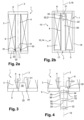
- FIG. 2a and 2b A first embodiment is illustrated in Figures 2a and 2b .
- the detachable plug 30 is placed in the central opening 7 so as to close it. It may be force-fitted or snapped in the filter element 1, for example on the first end plate 5 or in a variant (not represented) at the axial end 91 of the central perforated rigid tube 9 that is nearest the central opening 7.
- An annular gasket 33 may be provided between the detachable plug 30 and the first end plate 5 or between the detachable plug 30 and the central perforated rigid tube 9 to improve sealing.
- the detachable plug 30 may integrally be housed in the filter element 1, meaning that no portion of the detachable plug 30 protrudes outside of the filter element 1.
- the free end 21 of the axial member 20 comes into contact with the outer face 32 of the detachable plug 30, and the axial member 20 pushes the detachable plug 30 axially, towards the second end plate 6.
- the force exerted is high enough to detach, in other words to separate, the detachable plug 30 from the first end plate 5.
- the detachable plug 30, which is then free to move inside the channel 4, is pushed by the axial member 20 of the filter housing 14.
- the axial member 20 is long enough to push the detachable plug 30 substantially up to the second end plate 6, when the filter element 1 is fully inserted in the filter housing 14, as shown in Figure 2b .
- the detachable plug 30 is far enough from the first end plate 5 (namely located at least half way between the end plates 5, 6) to not impede too much liquid flow in the channel 4.
- radial holes 22 are required in the axial member ( figure 2b ) or, in a variant, in the detachable plug 30 (radial holes 37, figure 4 ), to allow the liquid flowing in the liquid filtering device 1.
- the detachable plug 30 may be attached to the first end plate 5 by a breakable connection. More specifically, the detachable plug 30 and the first end plate 5 may form one and a single piece before the first insertion of the filter element 1 in the filter housing 14, a weak zone being provided around the detachable plug 30. Such a weak zone may be an annular zone 34 having a lower thickness.
- a weak zone may be an annular zone 34 having a lower thickness.
- FIG. 4 Another variant is shown in Figure 4 . Contrary to Figures 2a and 3 , in which the detachable plug 30 is recessed with respect to or substantially level with the outer face of the first end plate 5 in its closed position, the detachable plug 30 in the embodiment of Figure 4 comprises a portion 35 which protrudes outside the filter element 1, before the first insertion of the filter element 1 in the filter housing 14.
- Such an outward protruding portion 35 may provide a guiding mean for the movement of the detachable plug 30 resulting from the axial pushing force exerted by the axial member 20 of the filter housing 14.
- the portion 35 may also comprise a concave portion 36, such as a cylindrical recess, which faces outwards of the filter element 1, and which is designed to receive the free end 21 of the axial member 20 (as shown in dotted line). Consequently, the portion of the detachable plug 30 which is located inside the channel 4 in the closed position can have a fairly small height.
- the risk for the detachable plug 30 to become jammed in the channel 4 - because of its small height - is low, insofar as the detachable plug 30 is efficiently guided along the axis 2 by the axial member 20 cooperating with the protruding portion 35.
- At least one radial hole 22 of the axial member 20 has to be located outside of the concave portion 36 when the axial member 20 and the detachable plug 30 cooperate, to provide a liquid passageway.
- the concave portion 36 may define in the protruding portion 35 of the detachable plug 30 an axial hole that opens outwards of the filter element through an axial opening 50 and at least one radial hole 37 could be provided in the detachable plug 30 that is in liquid communication with the axial opening 50 through the inside of the of the detachable plug 30, i.e. through said axial hole.
- Such a radial hole 37 is preferably arranged in the outward protruding portion 35, thereby not providing an access for contaminants towards the clean side of the filter element 1 when the detachable plug 30 is in the closed position.
- connection between the detachable plug 30 and the first end plate 5 is illustrated in Figure 4 as a breakable connection, the detachable plug 30 could alternatively be force fitted or snapped in the central opening 7.
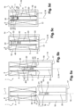
- FIG. 5a - 5d A second embodiment is illustrated in Figures 5a - 5d .
- the filter element 1 and the detachable plug 30 may be substantially identical to the embodiment of Figure 2a .
- the axial member 20 comprises at least one hole 22, and the axial member 20 further comprises a shutter 40 capable of closing this hole 22. More precisely, the shutter 40 is arranged at or near the free end 21 of the axial member 20 and can move with respect to the filter housing 14:
- a plurality of holes 22 could be provided in the axial member 20.
- the shutter 40 would be designed so as to close all holes, or several shutters would be provided so that all holes could be closed.
- the hole 22 is located near the free end 21 of the axial member 20.
- the shutter 40 is mounted in the axial member 20, near the free end 21 thereof.
- the shutter 40 comprises a closing portion 41, which can have a cylindrical outer face fitting with the inner face of the axial member 20, and an actuating portion 42 protruding from the closing portion 41 away from the filter housing bottom wall 17.
- the shutter 40 is configured to move axially with respect to the axial member 20:
- the filter housing 14 further comprises elastic means 43, such as for instance a spring, arranged to urge the shutter 40 towards its closed position.
- elastic means 43 such as for instance a spring
- the detachable plug 30 comes into contact with the shutter 40, more precisely with the actuating portion 42 of the shutter 40. Further insertion leads to the detachable plug 30 detaching from the filter element 1 and being pushed towards the second end plate 6, while the elastic means 43 still maintain the shutter 40 in its closed position ( Figure 5b ).
- the elastic means 43 are dimensioned not to compress, or to only slightly compress, when the detachable plug 30 is detached from the filter element 1 and pushed by the axial member 20, as long as the detachable plug 30 has not come into contact with the second end plate 6 of the filter element 1.
- the shutter 40 automatically returns to its closed position, due to the elastic means 43, thereby protecting the space inside the axial member 20 from contaminants.
- the filter element 1 is provided with a helical path 48 arranged on an inner face of the channel 4, such as a groove.
- the helical path 48 is preferably arranged in the central perforated rigid tube 9 of the channel 4 when the central perforated rigid tube 9 is provided.
- the detachable plug 30 comprises a guiding element 38 designed to be guided in the helical path 48, such as a radially protruding pin 38.
- the helical path 48 is "reversible", i.e. is such that an axial push exerted on the detachable plug 30 towards the second end plate 6 entails a rotation and an axial movement of the detachable plug 30 along the helical path 48 towards the second end plate 6.
- the detachable plug 30 when the detachable plug is in its detached position i.e. detached from first end plate 5 or from the central perforated rigid tube 9, the detachable plug 30 remains connected to the filter element 1 via the helical path 48 and can't move freely in the channel 4 because during its motion it is guided by the helical path 48.
- the axial member 20 may comprise a single radial hole 22 which, in the exemplary embodiment, is located near the free end 21 of the axial member 20.
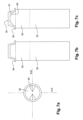
- the filter housing 14 further comprises a shutter 50 capable of closing this radial hole 22. More precisely, the shutter 50 is mounted on the axial member 20 near its free end 21 and can move with respect to the filter housing 14:
- the shutter 50 is mounted in the axial member 20, near the free end 21 thereof. It is configured as a cover having an axial end 51 and a peripheral wall 52 which for example fits the inner surface of the axial member 20. Furthermore, the shutter 50 is configured to move along a helical path 53 arranged in the axial member 20:
- the detachable plug 30 comes into axial abutment with the shutter 50, which is in the closed position.
- the detachable plug 30 and the shutter 50 comprise corresponding attaching or stopping means 60, 61 providing a rotationally fixed attachment.
- Stopping means 60, 61 can be realised by notches 60, for instance arranged on the shutter 50, and corresponding protruding portions 61, for instance arranged on the concave surface 39 of the detachable plug 30, that engage said notches 60 when the shutter 50 is in axial abutment against the detachable plug 30.
- the helical path 53 arranged in the axial member 20 has a screw thread smaller than the screw thread of the helical path 48 arranged in the central perforated rigid tube 9 of the filter element.
- the helical path 53 provided on the axial member 20 is further configured to prevent the shutter 50 from returning spontaneously to its closed position, when the liquid filtering device 1 is in use.
- locking means can be provided to lock the shutter 50 in its open position.
- the detachable plug 30 can have a coupling portion designed to receive and cooperate with the end portion 21 of the axial member 20, also forming a coupling portion.
- the coupling portions of the detachable plug 30 and of the axial member 20 have fitting shapes, namely respectively an outwardly facing concave portion 39 and a convex shape of the shutter 50.
- this entails an efficient cooperation between the detachable plug 30 and the axial member 20, improving the movement guidance. This also allows trapping possible contaminants between the detachable plug 30 and the axial member 20, so that these contaminants cannot be carried by the filtered liquid.
Landscapes
- Chemical & Material Sciences (AREA)
- Chemical Kinetics & Catalysis (AREA)
- Engineering & Computer Science (AREA)
- Combustion & Propulsion (AREA)
- Filtration Of Liquid (AREA)
Claims (10)
- Élément filtrant comprenant :- un milieu filtrant (3) ayant un axe (2) et formant un canal (4) s'étendant sensiblement axialement ;- une première et une seconde plaques d'extrémité (5, 6), chaque plaque d'extrémité recouvrant une extrémité axiale du milieu filtrant (3) et étant montée de manière étanche sur ladite extrémité axiale, la première plaque d'extrémité (5) ayant une ouverture centrale (7) sensiblement coaxiale et en communication fluidique avec le canal (4) ;l'élément filtrant (1) étant conçu pour être placé dans un logement de filtre (14) pour former un dispositif de filtration de liquide (10), moyennant quoi un liquide à filtrer peut s'écouler le long d'un trajet de liquide à travers le milieu filtrant (3) vers le canal (4) et hors de l'élément filtrant (1) à travers l'ouverture centrale (7),l'élément filtrant (1) comprenant en outre un bouchon détachable (30) dont la position peut changer d'une position attachée à une position détachée, où :- dans la position attachée, le bouchon détachable (30) est attaché à une partie immobile (5, 9) de l'élément filtrant (1) et scelle l'ouverture centrale (7),- dans la position détachée, le bouchon détachable est détaché de ladite partie immobile (5, 9) et peut se déplacer en s'éloignant de ladite ouverture centrale (7) à l'intérieur du canal (4) et le long de l'axe d'élément filtrant (2) pour desceller ladite ouverture centrale (7), jusqu'à une position finale où le bouchon détachable (30) est situé à distance de l'ouverture centrale (7) et où le bouchon détachable (30) est entièrement contenu dans le canal (4),caractérisé en ce que le canal (4) comprend une paroi interne perforée qui est réalisée par un tube rigide perforé central (9) qui s'étend axialement entre la première et la seconde plaques d'extrémité (5, 6), en ce que le tube rigide perforé central (9) comprend au moins une surface de guidage agencée à l'intérieur du tube rigide perforé central (9) pour guider le bouchon détachable (30) pendant son mouvement de l'ouverture centrale (7) jusqu'à la position finale, en ce que le changement de position de la position attachée à la position détachée du bouchon détachable (30) est irréversible, en ce que ladite au moins une surface de guidage est un trajet hélicoïdal (48) agencé sur une surface interne du tube rigide perforé central (9), et en ce que le bouchon détachable (30) comprend au moins un élément de guidage correspondant (38) conçu pour être guidé dans ledit trajet hélicoïdal (48) pendant le mouvement du bouchon détachable (30) de l'ouverture centrale (7) jusqu'à la position finale.
- Élément filtrant selon la revendication 1, caractérisé en ce que ladite position finale est située à distance de l'ouverture centrale (7) qui est supérieure à la moitié de la hauteur d'élément filtrant, le long de l'axe d'élément filtrant (2).
- Élément filtrant selon l'une quelconque des revendications 1 et 2, caractérisé en ce que dans ladite position finale, le bouchon détachable (30) est en contact axial avec la seconde plaque d'extrémité (6).
- Élément filtrant selon l'une quelconque des revendications 1 à 3, caractérisé en ce qu'il est conçu de sorte que le bouchon détachable (30) soit détaché de ladite partie immobile (5, 9) de l'élément filtrant (1) pour se déplacer à l'intérieur du canal (4) vers la seconde plaque d'extrémité (6) jusqu'à ladite position finale lorsqu'une force de poussée axiale est exercée sur le bouchon détachable (30) par un élément axial (20) du logement de filtre (14) pendant l'insertion de l'élément filtrant (1) dans le logement de filtre (14).
- Élément filtrant selon l'une quelconque des revendications précédentes, caractérisé en ce que le bouchon détachable (30) est attaché à ladite partie immobile (5, 9) de l'élément filtrant (1) via au moins l'une parmi : une liaison par encliquetage, une liaison par ajustement forcé, une liaison cassable.
- Élément filtrant selon l'une quelconque des revendications précédentes, caractérisé en ce que ladite partie immobile (5, 9) de l'élément filtrant (1) est la première plaque d'extrémité (5).
- Élément filtrant selon l'une quelconque des revendications 1 à 5, caractérisé en ce que ladite partie immobile (5, 9) de l'élément filtrant (1) est l'extrémité axiale (91) du tube rigide perforé central (9) qui se trouve sur le côté de l'ouverture centrale (7).
- Élément filtrant selon l'une quelconque des revendications 1 à 7, caractérisé en ce que le trajet hélicoïdal (48) est conçu de sorte qu'une poussée axiale exercée sur le bouchon détachable (30) vers la seconde plaque d'extrémité (6) entraîne un mouvement de rotation et un mouvement axial du bouchon détachable (30) le long du trajet hélicoïdal (48).
- Dispositif de filtration de liquide comprenant :- un élément filtrant (1) selon l'une quelconque des revendications 1 à 8 ;- un boîtier (13) recevant l'élément filtrant (1) et comprenant :l'ensemble constitué de l'élément axial (20) et du bouchon détachable (30) comprenant au moins un trou (22, 37) pour permettre au liquide de s'écouler de l'extérieur de l'ensemble vers l'intérieur.o un logement de filtre (14) ayant une paroi inférieure (17), une paroi périphérique (18), une ouverture principale (19) au niveau de son extrémité axiale opposée à la paroi inférieure (17), et un élément axial (20) qui est configuré pour être inséré dans le canal d'élément filtrant (4) et pour pousser le bouchon détachable (30) à l'intérieur dudit canal (4) vers la seconde plaque d'extrémité (6) pendant la première insertion de l'élément filtrant (1) dans le logement de filtre (14) ;o un couvercle de filtre (15) fixé de manière amovible au logement de filtre (14) au niveau de son ouverture principale (19),
- Véhicule, caractérisé en ce qu'il comprend un dispositif de filtration de liquide (10) selon la revendication 9, le dispositif de filtration de liquide (10) étant conçu pour filtrer un liquide tel que du carburant ou de l'huile.
Applications Claiming Priority (1)
| Application Number | Priority Date | Filing Date | Title |
|---|---|---|---|
| PCT/IB2016/000421 WO2017149344A1 (fr) | 2016-03-04 | 2016-03-04 | Élément de filtre destiné à un véhicule |
Publications (3)
| Publication Number | Publication Date |
|---|---|
| EP3423167A1 EP3423167A1 (fr) | 2019-01-09 |
| EP3423167B1 true EP3423167B1 (fr) | 2025-01-08 |
| EP3423167C0 EP3423167C0 (fr) | 2025-01-08 |
Family
ID=55702026
Family Applications (1)
| Application Number | Title | Priority Date | Filing Date |
|---|---|---|---|
| EP16715609.0A Active EP3423167B1 (fr) | 2016-03-04 | 2016-03-04 | Élément de filtre destiné à un véhicule |
Country Status (4)
| Country | Link |
|---|---|
| US (1) | US10874961B2 (fr) |
| EP (1) | EP3423167B1 (fr) |
| CN (1) | CN108697954B (fr) |
| WO (1) | WO2017149344A1 (fr) |
Families Citing this family (3)
| Publication number | Priority date | Publication date | Assignee | Title |
|---|---|---|---|---|
| WO2019242866A1 (fr) * | 2018-06-22 | 2019-12-26 | Volvo Truck Corporation | Élément filtrant, dispositif de filtrage de liquide comprenant un tel élément filtrant et véhicule comprenant un tel dispositif de filtrage de liquide |
| US20200289965A1 (en) * | 2019-03-11 | 2020-09-17 | Hamilton Sundstrand Corporation | Oil filter assembly for an integrated drive generator |
| DE102019206949A1 (de) * | 2019-05-14 | 2020-11-19 | Mahle International Gmbh | Filtereinrichtung zum Reinigen eines Fluides sowie Filterelement |
Citations (2)
| Publication number | Priority date | Publication date | Assignee | Title |
|---|---|---|---|---|
| US3272336A (en) * | 1965-04-05 | 1966-09-13 | Wix Corp | Liquid purifier and cleaner |
| EP0580491A1 (fr) * | 1992-07-23 | 1994-01-26 | Filtrauto | Perfectionnements aux cartouches filtrantes pour liquide et aux filtres équipés de telles cartouches |
Family Cites Families (12)
| Publication number | Priority date | Publication date | Assignee | Title |
|---|---|---|---|---|
| US7481320B2 (en) * | 2004-01-05 | 2009-01-27 | Ntz Nederland Bv | Filter device having a bi-directional valve |
| DE102007030278A1 (de) * | 2006-07-12 | 2008-01-24 | Mann + Hummel Gmbh | Filterelement |
| US7867387B2 (en) * | 2007-07-19 | 2011-01-11 | Cummins Filtration Ip, Inc. | Standpipe with flow restriction valve, and filter cartridge |
| US20090095665A1 (en) * | 2007-10-11 | 2009-04-16 | Gm Global Technology Operations, Inc. | Anti-Drainback Valve For An Oil Filter |
| US8920648B2 (en) * | 2009-02-25 | 2014-12-30 | Cummins Filtration Ip Inc. | No filter no run fluid filtration systems |
| US8517183B2 (en) * | 2009-05-04 | 2013-08-27 | Cummins Filtration Ip, Inc. | No filter no run fluid filtration system |
| CN102389661A (zh) * | 2011-09-30 | 2012-03-28 | 孙世博 | 一种折叶过滤组件及过滤系统 |
| US9597616B2 (en) * | 2012-10-12 | 2017-03-21 | Cummins Filtration Ip, Inc. | Fluid filter and head with quick connector |
| US20150251115A1 (en) * | 2013-03-16 | 2015-09-10 | West Troy, Llc | Fluid filter and relief valve assembly |
| CN105229294B (zh) * | 2013-05-28 | 2018-07-17 | 曼·胡默尔有限公司 | 过滤器元件 |
| CN104265931A (zh) * | 2014-10-21 | 2015-01-07 | 成都市翻鑫家科技有限公司 | 一种带过滤网的软密封旋塞阀 |
| CN204973229U (zh) * | 2015-08-25 | 2016-01-20 | 华岁喜 | 一种压力平衡自净过滤器 |
-
2016
- 2016-03-04 CN CN201680082936.0A patent/CN108697954B/zh active Active
- 2016-03-04 EP EP16715609.0A patent/EP3423167B1/fr active Active
- 2016-03-04 US US16/075,708 patent/US10874961B2/en active Active
- 2016-03-04 WO PCT/IB2016/000421 patent/WO2017149344A1/fr not_active Ceased
Patent Citations (2)
| Publication number | Priority date | Publication date | Assignee | Title |
|---|---|---|---|---|
| US3272336A (en) * | 1965-04-05 | 1966-09-13 | Wix Corp | Liquid purifier and cleaner |
| EP0580491A1 (fr) * | 1992-07-23 | 1994-01-26 | Filtrauto | Perfectionnements aux cartouches filtrantes pour liquide et aux filtres équipés de telles cartouches |
Also Published As
| Publication number | Publication date |
|---|---|
| US20190060802A1 (en) | 2019-02-28 |
| CN108697954B (zh) | 2021-09-28 |
| EP3423167A1 (fr) | 2019-01-09 |
| US10874961B2 (en) | 2020-12-29 |
| EP3423167C0 (fr) | 2025-01-08 |
| CN108697954A (zh) | 2018-10-23 |
| WO2017149344A1 (fr) | 2017-09-08 |
Similar Documents
| Publication | Publication Date | Title |
|---|---|---|
| USRE48122E1 (en) | Filter element endplate defining inflow and outflow flow paths | |
| EP2941578B1 (fr) | Capuchon d'extrémité en trois parties et élément filtrant le comprenant | |
| US20150151226A1 (en) | Filter system with fuel-water separator | |
| CN101842572B (zh) | 具有限流阀的竖管和滤筒 | |
| CA2380946C (fr) | Filtre a huile comprenant un actionneur de soupape a drainage rapide | |
| EP1201289B1 (fr) | Filtre avec élément de sécurité retenu | |
| US6936161B2 (en) | Fluid filter apparatus | |
| EP3423167B1 (fr) | Élément de filtre destiné à un véhicule | |
| JP2014505822A5 (fr) | ||
| JP2005500896A (ja) | フィルタ装置 | |
| US20190111363A1 (en) | A filter insert and a filter arrangement | |
| AU2018202913A1 (en) | Filter apparatus | |
| US20070221585A1 (en) | Collapsible Protective Cover for a Filter | |
| JP4190383B2 (ja) | 流体フィルタ及びそのドレン機構、流体フィルタに使用されるドレン用冶具並びに流体フィルタのドレン方法 | |
| EP3003524B1 (fr) | Ensemble de réceptacle de filtre avec dispositif de verrouillage | |
| EP3096856B1 (fr) | Élément de filtre possédant un tube de mise à l'air et ensemble de filtre | |
| US11931675B2 (en) | Filter element, liquid filtering device comprising such a filter element and vehicle comprising such a liquid filtering device | |
| ES2341479T3 (es) | Dispositivo de filtracion. | |
| US20070181487A1 (en) | Fluid filter with bypass valve failure protection | |
| WO2016008776A1 (fr) | Élément de filtration creux d'un filtre pour fluide, filtre et boîtier de filtre | |
| EP2488272B1 (fr) | Filtre à capuchon et utilisation | |
| HK1189189A1 (en) | Canister filter system with drain that cooperates with filter element | |
| CN105148586A (zh) | 液体过滤器 | |
| JP2003041920A (ja) | フィルタ装置 |
Legal Events
| Date | Code | Title | Description |
|---|---|---|---|
| STAA | Information on the status of an ep patent application or granted ep patent |
Free format text: STATUS: THE INTERNATIONAL PUBLICATION HAS BEEN MADE |
|
| PUAI | Public reference made under article 153(3) epc to a published international application that has entered the european phase |
Free format text: ORIGINAL CODE: 0009012 |
|
| STAA | Information on the status of an ep patent application or granted ep patent |
Free format text: STATUS: REQUEST FOR EXAMINATION WAS MADE |
|
| 17P | Request for examination filed |
Effective date: 20181003 |
|
| AK | Designated contracting states |
Kind code of ref document: A1 Designated state(s): AL AT BE BG CH CY CZ DE DK EE ES FI FR GB GR HR HU IE IS IT LI LT LU LV MC MK MT NL NO PL PT RO RS SE SI SK SM TR |
|
| AX | Request for extension of the european patent |
Extension state: BA ME |
|
| DAV | Request for validation of the european patent (deleted) | ||
| DAX | Request for extension of the european patent (deleted) | ||
| STAA | Information on the status of an ep patent application or granted ep patent |
Free format text: STATUS: EXAMINATION IS IN PROGRESS |
|
| 17Q | First examination report despatched |
Effective date: 20191217 |
|
| GRAP | Despatch of communication of intention to grant a patent |
Free format text: ORIGINAL CODE: EPIDOSNIGR1 |
|
| STAA | Information on the status of an ep patent application or granted ep patent |
Free format text: STATUS: GRANT OF PATENT IS INTENDED |
|
| GRAS | Grant fee paid |
Free format text: ORIGINAL CODE: EPIDOSNIGR3 |
|
| INTG | Intention to grant announced |
Effective date: 20241031 |
|
| GRAA | (expected) grant |
Free format text: ORIGINAL CODE: 0009210 |
|
| STAA | Information on the status of an ep patent application or granted ep patent |
Free format text: STATUS: THE PATENT HAS BEEN GRANTED |
|
| AK | Designated contracting states |
Kind code of ref document: B1 Designated state(s): AL AT BE BG CH CY CZ DE DK EE ES FI FR GB GR HR HU IE IS IT LI LT LU LV MC MK MT NL NO PL PT RO RS SE SI SK SM TR |
|
| REG | Reference to a national code |
Ref country code: GB Ref legal event code: FG4D |
|
| REG | Reference to a national code |
Ref country code: CH Ref legal event code: EP |
|
| REG | Reference to a national code |
Ref country code: DE Ref legal event code: R096 Ref document number: 602016090886 Country of ref document: DE |
|
| REG | Reference to a national code |
Ref country code: IE Ref legal event code: FG4D |
|
| U01 | Request for unitary effect filed |
Effective date: 20250205 |
|
| U07 | Unitary effect registered |
Designated state(s): AT BE BG DE DK EE FI FR IT LT LU LV MT NL PT RO SE SI Effective date: 20250211 |
|
| U20 | Renewal fee for the european patent with unitary effect paid |
Year of fee payment: 10 Effective date: 20250331 |
|
| PG25 | Lapsed in a contracting state [announced via postgrant information from national office to epo] |
Ref country code: RS Free format text: LAPSE BECAUSE OF FAILURE TO SUBMIT A TRANSLATION OF THE DESCRIPTION OR TO PAY THE FEE WITHIN THE PRESCRIBED TIME-LIMIT Effective date: 20250408 |
|
| PG25 | Lapsed in a contracting state [announced via postgrant information from national office to epo] |
Ref country code: PL Free format text: LAPSE BECAUSE OF FAILURE TO SUBMIT A TRANSLATION OF THE DESCRIPTION OR TO PAY THE FEE WITHIN THE PRESCRIBED TIME-LIMIT Effective date: 20250108 |
|
| PG25 | Lapsed in a contracting state [announced via postgrant information from national office to epo] |
Ref country code: ES Free format text: LAPSE BECAUSE OF FAILURE TO SUBMIT A TRANSLATION OF THE DESCRIPTION OR TO PAY THE FEE WITHIN THE PRESCRIBED TIME-LIMIT Effective date: 20250108 |
|
| PG25 | Lapsed in a contracting state [announced via postgrant information from national office to epo] |
Ref country code: NO Free format text: LAPSE BECAUSE OF FAILURE TO SUBMIT A TRANSLATION OF THE DESCRIPTION OR TO PAY THE FEE WITHIN THE PRESCRIBED TIME-LIMIT Effective date: 20250408 Ref country code: IS Free format text: LAPSE BECAUSE OF FAILURE TO SUBMIT A TRANSLATION OF THE DESCRIPTION OR TO PAY THE FEE WITHIN THE PRESCRIBED TIME-LIMIT Effective date: 20250508 |
|
| PG25 | Lapsed in a contracting state [announced via postgrant information from national office to epo] |
Ref country code: HR Free format text: LAPSE BECAUSE OF FAILURE TO SUBMIT A TRANSLATION OF THE DESCRIPTION OR TO PAY THE FEE WITHIN THE PRESCRIBED TIME-LIMIT Effective date: 20250108 |
|
| PG25 | Lapsed in a contracting state [announced via postgrant information from national office to epo] |
Ref country code: GR Free format text: LAPSE BECAUSE OF FAILURE TO SUBMIT A TRANSLATION OF THE DESCRIPTION OR TO PAY THE FEE WITHIN THE PRESCRIBED TIME-LIMIT Effective date: 20250409 |
|
| PG25 | Lapsed in a contracting state [announced via postgrant information from national office to epo] |
Ref country code: SM Free format text: LAPSE BECAUSE OF FAILURE TO SUBMIT A TRANSLATION OF THE DESCRIPTION OR TO PAY THE FEE WITHIN THE PRESCRIBED TIME-LIMIT Effective date: 20250108 |
|
| PG25 | Lapsed in a contracting state [announced via postgrant information from national office to epo] |
Ref country code: MC Free format text: LAPSE BECAUSE OF FAILURE TO SUBMIT A TRANSLATION OF THE DESCRIPTION OR TO PAY THE FEE WITHIN THE PRESCRIBED TIME-LIMIT Effective date: 20250108 |
|
| PG25 | Lapsed in a contracting state [announced via postgrant information from national office to epo] |
Ref country code: CZ Free format text: LAPSE BECAUSE OF FAILURE TO SUBMIT A TRANSLATION OF THE DESCRIPTION OR TO PAY THE FEE WITHIN THE PRESCRIBED TIME-LIMIT Effective date: 20250108 |
|
| REG | Reference to a national code |
Ref country code: CH Ref legal event code: H13 Free format text: ST27 STATUS EVENT CODE: U-0-0-H10-H13 (AS PROVIDED BY THE NATIONAL OFFICE) Effective date: 20251024 |
|
| PG25 | Lapsed in a contracting state [announced via postgrant information from national office to epo] |
Ref country code: SK Free format text: LAPSE BECAUSE OF FAILURE TO SUBMIT A TRANSLATION OF THE DESCRIPTION OR TO PAY THE FEE WITHIN THE PRESCRIBED TIME-LIMIT Effective date: 20250108 |
|
| PLBE | No opposition filed within time limit |
Free format text: ORIGINAL CODE: 0009261 |
|
| STAA | Information on the status of an ep patent application or granted ep patent |
Free format text: STATUS: NO OPPOSITION FILED WITHIN TIME LIMIT |
|
| 26N | No opposition filed |
Effective date: 20251009 |
|
| GBPC | Gb: european patent ceased through non-payment of renewal fee |
Effective date: 20250408 |
|
| PG25 | Lapsed in a contracting state [announced via postgrant information from national office to epo] |
Ref country code: GB Free format text: LAPSE BECAUSE OF NON-PAYMENT OF DUE FEES Effective date: 20250408 |
|
| PG25 | Lapsed in a contracting state [announced via postgrant information from national office to epo] |
Ref country code: CH Free format text: LAPSE BECAUSE OF NON-PAYMENT OF DUE FEES Effective date: 20250331 |
|
| PG25 | Lapsed in a contracting state [announced via postgrant information from national office to epo] |
Ref country code: IE Free format text: LAPSE BECAUSE OF NON-PAYMENT OF DUE FEES Effective date: 20250304 |
|
| U20 | Renewal fee for the european patent with unitary effect paid |
Year of fee payment: 11 Effective date: 20260323 |