EP3423716B1 - System zur verwendung von druckluft als kraftquelle und verfahren dafür; flugzeug - Google Patents
System zur verwendung von druckluft als kraftquelle und verfahren dafür; flugzeug Download PDFInfo
- Publication number
- EP3423716B1 EP3423716B1 EP17760385.9A EP17760385A EP3423716B1 EP 3423716 B1 EP3423716 B1 EP 3423716B1 EP 17760385 A EP17760385 A EP 17760385A EP 3423716 B1 EP3423716 B1 EP 3423716B1
- Authority
- EP
- European Patent Office
- Prior art keywords
- air
- engine
- pressure
- compressed air
- manifold
- Prior art date
- Legal status (The legal status is an assumption and is not a legal conclusion. Google has not performed a legal analysis and makes no representation as to the accuracy of the status listed.)
- Active
Links
Images


Classifications
-
- F—MECHANICAL ENGINEERING; LIGHTING; HEATING; WEAPONS; BLASTING
- F03—MACHINES OR ENGINES FOR LIQUIDS; WIND, SPRING, OR WEIGHT MOTORS; PRODUCING MECHANICAL POWER OR A REACTIVE PROPULSIVE THRUST, NOT OTHERWISE PROVIDED FOR
- F03H—PRODUCING A REACTIVE PROPULSIVE THRUST, NOT OTHERWISE PROVIDED FOR
- F03H99/00—Subject matter not provided for in other groups of this subclass
-
- B—PERFORMING OPERATIONS; TRANSPORTING
- B60—VEHICLES IN GENERAL
- B60K—ARRANGEMENT OR MOUNTING OF PROPULSION UNITS OR OF TRANSMISSIONS IN VEHICLES; ARRANGEMENT OR MOUNTING OF PLURAL DIVERSE PRIME-MOVERS IN VEHICLES; AUXILIARY DRIVES FOR VEHICLES; INSTRUMENTATION OR DASHBOARDS FOR VEHICLES; ARRANGEMENTS IN CONNECTION WITH COOLING, AIR INTAKE, GAS EXHAUST OR FUEL SUPPLY OF PROPULSION UNITS IN VEHICLES
- B60K3/00—Arrangement or mounting of steam or gaseous-pressure propulsion units
- B60K3/04—Arrangement or mounting of steam or gaseous-pressure propulsion units of turbine type
-
- B—PERFORMING OPERATIONS; TRANSPORTING
- B64—AIRCRAFT; AVIATION; COSMONAUTICS
- B64C—AEROPLANES; HELICOPTERS
- B64C15/00—Attitude, flight direction, or altitude control by jet reaction
- B64C15/14—Attitude, flight direction, or altitude control by jet reaction the jets being other than main propulsion jets
-
- B—PERFORMING OPERATIONS; TRANSPORTING
- B64—AIRCRAFT; AVIATION; COSMONAUTICS
- B64C—AEROPLANES; HELICOPTERS
- B64C23/00—Influencing air flow over aircraft surfaces, not otherwise provided for
-
- B—PERFORMING OPERATIONS; TRANSPORTING
- B64—AIRCRAFT; AVIATION; COSMONAUTICS
- B64C—AEROPLANES; HELICOPTERS
- B64C23/00—Influencing air flow over aircraft surfaces, not otherwise provided for
- B64C23/04—Influencing air flow over aircraft surfaces, not otherwise provided for by generating shock waves
-
- B—PERFORMING OPERATIONS; TRANSPORTING
- B64—AIRCRAFT; AVIATION; COSMONAUTICS
- B64D—EQUIPMENT FOR FITTING IN OR TO AIRCRAFT; FLIGHT SUITS; PARACHUTES; ARRANGEMENT OR MOUNTING OF POWER PLANTS OR PROPULSION TRANSMISSIONS IN AIRCRAFT
- B64D27/00—Arrangement or mounting of power plants in aircraft; Aircraft characterised by the type or position of power plants
- B64D27/02—Aircraft characterised by the type or position of power plants
-
- B—PERFORMING OPERATIONS; TRANSPORTING
- B64—AIRCRAFT; AVIATION; COSMONAUTICS
- B64D—EQUIPMENT FOR FITTING IN OR TO AIRCRAFT; FLIGHT SUITS; PARACHUTES; ARRANGEMENT OR MOUNTING OF POWER PLANTS OR PROPULSION TRANSMISSIONS IN AIRCRAFT
- B64D27/00—Arrangement or mounting of power plants in aircraft; Aircraft characterised by the type or position of power plants
- B64D27/02—Aircraft characterised by the type or position of power plants
- B64D27/16—Aircraft characterised by the type or position of power plants of jet type
- B64D27/18—Aircraft characterised by the type or position of power plants of jet type within, or attached to, wings
-
- B—PERFORMING OPERATIONS; TRANSPORTING
- B64—AIRCRAFT; AVIATION; COSMONAUTICS
- B64D—EQUIPMENT FOR FITTING IN OR TO AIRCRAFT; FLIGHT SUITS; PARACHUTES; ARRANGEMENT OR MOUNTING OF POWER PLANTS OR PROPULSION TRANSMISSIONS IN AIRCRAFT
- B64D27/00—Arrangement or mounting of power plants in aircraft; Aircraft characterised by the type or position of power plants
- B64D27/02—Aircraft characterised by the type or position of power plants
- B64D27/16—Aircraft characterised by the type or position of power plants of jet type
- B64D27/20—Aircraft characterised by the type or position of power plants of jet type within, or attached to, fuselages
-
- B—PERFORMING OPERATIONS; TRANSPORTING
- B64—AIRCRAFT; AVIATION; COSMONAUTICS
- B64D—EQUIPMENT FOR FITTING IN OR TO AIRCRAFT; FLIGHT SUITS; PARACHUTES; ARRANGEMENT OR MOUNTING OF POWER PLANTS OR PROPULSION TRANSMISSIONS IN AIRCRAFT
- B64D41/00—Power installations for auxiliary purposes
-
- B—PERFORMING OPERATIONS; TRANSPORTING
- B64—AIRCRAFT; AVIATION; COSMONAUTICS
- B64G—COSMONAUTICS; VEHICLES OR EQUIPMENT THEREFOR
- B64G1/00—Cosmonautic vehicles
- B64G1/22—Parts of, or equipment specially adapted for fitting in or to, cosmonautic vehicles
- B64G1/24—Guiding or controlling apparatus, e.g. for attitude control
- B64G1/26—Guiding or controlling apparatus, e.g. for attitude control using jets
-
- B—PERFORMING OPERATIONS; TRANSPORTING
- B64—AIRCRAFT; AVIATION; COSMONAUTICS
- B64G—COSMONAUTICS; VEHICLES OR EQUIPMENT THEREFOR
- B64G1/00—Cosmonautic vehicles
- B64G1/22—Parts of, or equipment specially adapted for fitting in or to, cosmonautic vehicles
- B64G1/40—Arrangements or adaptations of propulsion systems
-
- F—MECHANICAL ENGINEERING; LIGHTING; HEATING; WEAPONS; BLASTING
- F02—COMBUSTION ENGINES; HOT-GAS OR COMBUSTION-PRODUCT ENGINE PLANTS
- F02C—GAS-TURBINE PLANTS; AIR INTAKES FOR JET-PROPULSION PLANTS; CONTROLLING FUEL SUPPLY IN AIR-BREATHING JET-PROPULSION PLANTS
- F02C1/00—Gas-turbine plants characterised by the use of hot gases or unheated pressurised gases, as the working fluid
- F02C1/04—Gas-turbine plants characterised by the use of hot gases or unheated pressurised gases, as the working fluid the working fluid being heated indirectly
-
- F—MECHANICAL ENGINEERING; LIGHTING; HEATING; WEAPONS; BLASTING
- F02—COMBUSTION ENGINES; HOT-GAS OR COMBUSTION-PRODUCT ENGINE PLANTS
- F02C—GAS-TURBINE PLANTS; AIR INTAKES FOR JET-PROPULSION PLANTS; CONTROLLING FUEL SUPPLY IN AIR-BREATHING JET-PROPULSION PLANTS
- F02C7/00—Features, components parts, details or accessories, not provided for in, or of interest apart form groups F02C1/00 - F02C6/00; Air intakes for jet-propulsion plants
- F02C7/04—Air intakes for gas-turbine plants or jet-propulsion plants
-
- Y—GENERAL TAGGING OF NEW TECHNOLOGICAL DEVELOPMENTS; GENERAL TAGGING OF CROSS-SECTIONAL TECHNOLOGIES SPANNING OVER SEVERAL SECTIONS OF THE IPC; TECHNICAL SUBJECTS COVERED BY FORMER USPC CROSS-REFERENCE ART COLLECTIONS [XRACs] AND DIGESTS
- Y02—TECHNOLOGIES OR APPLICATIONS FOR MITIGATION OR ADAPTATION AGAINST CLIMATE CHANGE
- Y02T—CLIMATE CHANGE MITIGATION TECHNOLOGIES RELATED TO TRANSPORTATION
- Y02T50/00—Aeronautics or air transport
- Y02T50/40—Weight reduction
Definitions
- This invention relates to the field of engine technology, particularly providing a system of using compressed air as a force source and method thereof, more specifically an airplane.
- Engine is a machine capable to convert other forms of energy into mechanical energy. Born in Britain, it has gone through the development stages of external and internal combustion engines in succession.
- a fuel burns in the external part of the engine, such as steam engines.
- a fuel burns in the internal part of an engine, such as a type of gasoline, diesel and jet engines. In fact, whether an engine has external or internal combustion, the combustion effect is to produce a "high-temperature and high-pressure" gas to work in the engine.
- the present invention aims at exploring the use of "high pressure” compressed air as a power source to output thrust, and providing a system of using compressed air as a force source.
- turbojet turbojet
- axial flow turbojet turbofan
- ramjet ramjet
- pulsejet turbojet engines
- the rocket engines include chemical rocket, electric rocket, nuclear rocket, and solar rocket among others.
- the chemical rocket engines have been currently developed in more mature and wider application, so that the rocket engines generally refer to the chemical rocket engines, which can be classified into liquid rocket engines and solid rocket motors.
- the turbojet include 1 intake channel, through which air enter a compressor in next structure; 2 compressor, consisting of stator blades and rotor blades in staggered composition, where a pair of stator and rotor blades is termed as one grade (usually 8-12 grades), where the stator fixed to the engine frame while the rotor with its shaft connected to the turbine; 3 combustion chamber and turbine where air, after compressed by the compressor, enters the combustion chamber for mixing with the fuel to burn, producing the high-temperature and high-pressure gas for expansion to do work, and flowing through the turbine to drive it (most of modern fighters have an afterburner installed after the turbine to increase engine thrust); 4 nozzle (also known as muzzle), which shape and structure of convergence, convergence-divergence tube determine the final state of the exhaust gas stream.
- 2 compressor consisting of stator blades and rotor blades in staggered composition, where a pair of stator and rotor blades is termed as one grade (usually 8-12 grades), where the stator fixed to the engine frame while the
- Liquid rocket engines are those using a liquid propellant, typically including 1 main push ejector, an important component to convert chemical energy of the liquid propellant (fuel and oxidizer) into the thrust, consisting of propellant nozzle, combustion chamber and nozzle assemblies among others (fuel and oxidizer get atomization through the propellant nozzle to spray into the combustion chamber where mixing-burning and producing a high-temperature and high-pressure gas ejecting out from the nozzle assembly); 2 propellant supply system, consisting fuel and oxidizer tanks, fuel and oxidizer pumps, fuel and oxidant delivery pipes and valves among others; 3 engine control system, collaboratively consisting of computerized controller and sensors measuring various parameters of the engine system, various types of valves and regulators; and 4 ignition device (ignition as soon as the propellant enters the combustion chamber) among others.
- 1 main push ejector an important component to convert chemical energy of the liquid propellant (fuel and oxidizer) into the thrust, consisting of propellant nozzle, combustion chamber and nozzle assemblies among others (fuel and
- Solid rocket motors are those using a solid propellant, including 1 grain (propellant charge), 2 combustion chamber (casing), 3 the nozzle assembly, and 4 ignition device among others.
- the grain is a hollow cylinder (hollow part is the combustion section, with a cross-section in circular, star or other shape) made of a solid propellant (fuel and oxidizer) well mixed in advance, loaded directly into a storage chamber, which is the combustion chamber when working, where the propellant burns to produce a high-temperature and high-pressure gas;
- the nozzle assembly consists of nozzle and thrust vector control system;
- the ignition device usually consists of electrical ignition tube and gunpowder cartridge to ignite the grain.
- a rocket engine uses the above-mentioned special structure - the half-closed combustion chamber is connected to the nozzle (de Laval nozzle), a structure giving the burning gas only single way - flowing to the direction of nozzle, while other directions are restricted. Therefore, the gas within the combustion chamber can establish a certain pressure (1 ⁇ 20MPa), while the pressure outside the nozzle is only 0.1 MPa (sea-level atmospheric pressure) or less than 0.1 MPa or even zero (at high altitude or even beyond atmosphere), so that, under the action of difference between internal and external pressures, the gas flows to the nozzle and ejects out at a high velocity.
- the "high-temperature and high-pressure” gas is produced within the jet engine combustion chamber mentioned above, and gets an action force applied by the inner wall of the engine combustion chamber under "high pressure” to flow to the nozzle.
- the gas leaving from the engine must give a counteraction to the engine, which is the thrust of the engine.
- the existing technology jet engine carry its own propellant (fuel or fuel plus oxidant) and combustion-related facilities, which is relevant to the problems of the engines of heavier weight, complex structure, difficulty in control, high cost, and difficulties in research, development and production.
- an aviation jet engine carries its own fuel oil, and also the multi-stage compressor, multi-stage turbine, multi-stage fan and others installed for its need to take air from the atmosphere as the oxidant to react with the fuel oil for combustion, which increases not only the weight but also greatly the difficulties in research, development and manufacture.
- the difficulties reach such an extent that: the first class turbofan engine technology in the world is mastered just by a few companies, such as Rolls-Royce Group pic, LSE: RR in UK, Pratt & Whitney and GE aviation in USA.
- Tsiolkovsky ( , 1857-1935), is considered to be one of the founding fathers of rocketry and astronautics, the first who proposed that Mass Ratio, the ratio of the rocket's initial mass to its final mass, is used to measure the efficiency of a rocket. He calculated that mass ratio is 23.5 for a rocket using nitric acid and hydrazine type propellants to reach the first cosmic speed, meaning that a rocket with total weight of 100 tons requires 96 tons of propellant; if coupled with gravity factor, the mass ratio will be even greater, i.e. the ratio of its payload to take-off mass will be further smaller.
- ZL201110351539.8 inventor: Lifeng Wang
- a device for launching payload and a rotary flywheel for cargo transportation, respectively capable to use the high-speed rotation of a flywheel to eject the payload at a high speed, and to reduce the transportation difficulty related to the payload weight, which mainly involve the use of principles and technical approaches of flywheel beyond the field of the rocket technology.
- How to reduce the rocket mass ratio, or on the other hand how to improve the ratio of rocket payload to its take-off mass, has always been a subject to be solved for the people in the field.
- Attitude and orbit control propulsion techniques usually involve chemical propulsion, cool gas propulsion, electric propulsion, nuclear propulsion, momentum transfer propulsion and non-working medium propulsion system among others, to accomplish three functions: attitude control (maintaining flight vehicle aiming at the designated direction), keeping track (maintaining flight vehicle travelling on the designated track) and orbit transfer (enabling flight vehicle to move from the current track to another designated track).
- attitude control maintaining flight vehicle aiming at the designated direction
- keeping track maintaining flight vehicle travelling on the designated track
- orbit transfer enabling flight vehicle to move from the current track to another designated track.
- a cool gas propulsion system i.e.
- cool gas propulsion technology for attitude and orbit control, generally uses compressed gas (such as air, nitrogen, helium, carbon dioxide, etc.) as the jet working medium.
- compressed gas such as air, nitrogen, helium, carbon dioxide, etc.
- a typical cool gas propulsion system usually outputs a thrust in a range of 0.05N-22N, providing a thrust or torque required for spacecraft attitude control, orbit transfer and keeping track.
- MEMS Microelectromechanical system
- the technology of Microelectromechanical system (MEMS) used in cool gas propulsion systems is easy to implement system miniaturization and integration, constituting the micro propulsion device, with the rapid development of microelectronics, micro-mechanical, lightweight composite materials and ultra-precision machining and other basic industries, may be integrally mounted on the mounting bulkhead for easy installation and replacement, and as the cool gas micro-propulsion system, it has been successfully applied to the practice and research on cool gas propulsion system for micro- and nano-satellites (usually, satellites in weight > 1000kg called Large satellite, weight of 500kg ⁇ 1000kg Medium satellite, 100kg ⁇ 500kg Mini satellite, 10kg ⁇ 100kg Micro satellite, and 1kg ⁇ 10kg Nano satellite, 0.1kg ⁇ 1kg Pico satellite, ⁇ 0.1kg Femto satellite).
- satellites in weight > 1000kg called Large satellite weight of 500kg ⁇ 1000kg Medium satellite, 100kg ⁇ 500kg Mini satellite, 10kg ⁇ 100kg Micro satellite, and 1kg ⁇ 10kg Nano satellite, 0.1kg
- an engine that uses a lot of its own carried high-pressure compressed air as a jet working medium may also provide the thrust.
- an airborne device can store a sufficient amount of high/ultrahigh pressure compressed air to supply the engine as a working medium, hereby simplified as "air tank”, referred to the structure and function of the automobile air storage tubes involved in a patent "A System for Economical Use of Compressed Air as an Automobile Power Source and Method Thereof" (Patent No. ZL201520365135.8 , PCT/SE2016/000030 , inventor: Lifeng Wang) with improvement in design.
- compressed air jet engine While for the engine of using high/ultra-high pressure compressed air for expansion work, hereby simplified as “compressed air jet engine”, and its structure and function (such as expansion chamber and nozzle), one can refer to the traditional jet engines structure and function (such as combustion chamber and nozzles) for liquid rocket with improvement of the design.
- So-called compressed air jet engines of using high/ultra-high pressure compressed air as the working medium provides thrust according to Newton's law (mainly Third Law, as well as Second Law), and can be used for airplane, rockets, ships, vehicles and other moving carriers.
- the traditional jet engine nozzles that should not be nearby, even less to face the moving carrier itself, because the scorching hot gas ejecting from the nozzles may ablate the surface of the carrier or at least increase the thermal fatigue of the carrier structure, causing severe consequence; while the temperature of the airflow ejecting from the compressed air jet engine nozzles is not so high, such ejected high-speed airflow can be quite close and parallel to the surface of the moving carrier, can be directly blowing over the upper surface of the wings, even can be at a certain distance and in a range of certain angles sloped against the surrounding of the head of the moving carrier, without taking into account the ablative damage to the moving carrier.
- the nozzles of a traditional jet engine due to its close relevance to the fuel combustion, usually appear only in the ordinary positions for installation of a main engine, such as at the rear part of the moving carrier, or beneath the wings, while the nozzles of a compressed air jet engine can not only appear in those ordinary positions, but also actually be installed in almost any of required places surrounding the moving carrier, just needing to get an intake pipe of high/ultra-high pressure compressed air communicating there.
- the nozzles of compressed air jet engine may be installed on the front part of a moving carrier, its body surroundings, front of wings among others, where to eject high-speed airflow, affecting the relevant local aerodynamic changes, sharp drop in air density and pressure, which can produce hydrodynamic effects on the movement of the moving carrier, to get these compressed air jet engines, in addition to the aforementioned thrust, the functions of reducing the running resistance such as air resistance and friction, and increasing wing lifting force, etc.
- the nozzle of the compressed air jet engines can be placed downward beneath an airplane fuselage to produce certain vertical upward thrust in favor of short-distance takeoff, or forward beneath the fuselage tail or on its both sides to eject airflow at a certain rate for buffering and deceleration of the travelling airplane in favor of short-distance landing. It can be described as all-round and multi-functional.
- the designated air pressure of the "air tank” is also very high, and when the pressure of the compressed air in the "compressed air production/supply device” drops to the extent equal to the air pressure in the "air tank” of the compressed air jet engine, there is a problem with that a large amount of high pressure compressed air remaining in the "compressed air production/supply device" cannot be utilized.
- the US 6,517,026 B1 discloses a vertical take-off and landing vehicle for land, water and air transport which is submersible and utilizes compressed air to lift and propel said vehicle during travel.
- the land-based drive train and the aviatic air compression system are powered mechanically by the vehicle's engine or electrically by rechargeable battery banks and generators or a combination thereof.
- the US 2013/068876 A1 discloses a vehicle having a roadable configuration similar to an automobile in which multiple rotors are stowed within the vehicle, and a flying configuration in which the rotors are deployed from the vehicle, allowing it to fly like a VTOL/STOL aircraft or a helicopter.
- the US 3,302,602 A discloses vessels capable of travelling on, below or above water and above land.
- the KR 2010/0046754 A discloses a linear ram-jet engine comprising an inlet port, an air tank, a first air compressor and a second air compressor, a laser beam ignition part and a nozzle.
- the inlet port draws in the external air.
- the air tank receives fuel through fuel supply pipe extended along the length of the inlet port.
- the air tank forms a space for generating mixed gas and igniting the mixed gas.
- the first and second air compressors are extended along the length of the inlet port.
- the first and second air compressors generate compressed air by drawing in external air.
- the first and second air compressors are inserted into the air tank through first and second supply pipes.
- the laser beam ignition part ignites mixed gas by emitting laser to the inside of the air tank.
- the nozzle is extended to correspond to the extended length of the inlet port.
- the technical problem to be solved is the economical use of high/ultrahigh pressure compressed air as force source, to provide a compressed air jet engine arranged on a moving carrier of aviation, aerospace, navigation and ground vehicles such as an airplane, a rocket, a submarine, a train or the like, using the compressed air as a jet working medium, for generating thrust, reducing air (or seawater) resistance, improving airplane wings lift, and to facilitate the speed-rising and energy-saving.
- this invention provides a system of using compressed air as force source, comprising compressed air jet engines to use high/ultra-high pressure compressed air as a jet working medium, a compressed air production/supply device and a controller.
- the compressed air jet engines are equipped on a moving carrier, comprising an air tank and air engines;
- the air tank is a compressed air storage container, including a plurality of air storage pipes to store and supply the compressed air needed for the air engines;
- the air engines comprise a main air engine and a plurality of auxiliary air engines;
- the main air engine is to use the compressed air input from the air storage pipes as the jet working medium for applying a thrust to the moving carrier moving forward;
- the plurality of auxiliary air engines arranged respectively around the moving carrier include first auxiliary air engine, second auxiliary air engine, third auxiliary air engine, fourth auxiliary air engine and fifth auxiliary air engine, to use the compressed air input from the air storage pipes as the jet working medium, in coordination with the main air engine for pushing the moving carrier moving toward the target direction.
- the compressed air production/supply device comprises a high/ultrahigh pressure air compressor and a large boiler-type pressure vessel; the working pressure of the high/ultrahigh pressure air compressor is close to, equal to or more than 100Mpa, for pressurizing and inflating air into the large boiler-type pressure vessel under the control of the controller; the large boiler-type pressure vessel is used to produce and store the compressed air for pressurizing and inflating the compressed air into plurality of the air storage pipes.
- the controller is used to control the opening and closing of the main air engine, first auxiliary air engine, second auxiliary air engine, third auxiliary air engine, fourth auxiliary air engine s and fifth auxiliary air engine for pushing the moving carrier moving toward the target direction.
- each of the main air engine, first auxiliary air engine, second auxiliary air engine, third auxiliary air engine, fourth auxiliary air engines and fifth auxiliary air engine comprises a high pressure-resistant, lighter material intake pipe, an expansion chamber and de Laval nozzle; wherein, the intake pipe is connected to the air storage pipe and the expansion chamber, and surrounded with an intake pipe electric heater, for heating the compressed air in the intake pipe to increase the air pressure within the intake pipe; the compressed air in air storage pipe is injected into the expansion chamber through the air injection vent of intake pipe; wherein, the expansion chamber wall of expansion chamber is equipped with an air injection adjuster for modulating the amount of compressed air at a set pressure injected from the intake pipe into the expansion chamber to maintain the pressure within the expansion chamber at the set pressure; surrounding the expansion chamber there is a expansion chamber wall electric heater to heat the compressed air entering the expansion chamber for pressurization; wherein, the cross-sectional area of de Laval nozzle is first converged and then diverged; the rear of the expansion chamber is integrally connected with de Laval nozzle
- first auxiliary air engine is equipped at the front of the moving carrier head; the cross section area of first auxiliary air engine is smaller than that of the corresponding moving carrier head; first auxiliary air engine comprises first intake pipe, first expansion chamber and first de Laval nozzle, as well as a firm tubular structure, through which first auxiliary air engine is fixed at the front of the moving carrier head; first intake pipe is located within the firm tubular structure, and supported by the firm tubular structure; the rear of first expansion chamber is integrally connected with first de Laval nozzle convergent section; whole first de Laval nozzle has de Laval nozzle-like structure from front to rear; first intake pipe, along with the firm tubular structure , extends forward from the moving carrier head, and forward passes through first auxiliary air engine nozzle, first de Laval nozzle divergent section, first de Laval nozzle throat, first de Laval nozzle convergent section and first expansion chamber in sequence along with the axial center of first auxiliary air engine to be fixedly connected with first expansion chamber head inner wall, on which first air injection
- second auxiliary air engines are placed around the moving carrier with their nozzles toward the rear of the moving carrier to eject high-velocity airflow for applying thrust to the moving carrier forward; moreover, the high-velocity airflow ejected by the nozzles of second auxiliary air engines is parallel and close to the surface of the moving carrier, so that a low-pressure air layer is formed around the moving carrier, thus reducing sliding friction resistance between the moving carrier and its surroundings when it moves forward.
- the moving carrier is equipped with one or more air tanks, in each of air tanks there are several air storage pipes which have a long tubular structure with a cylindrical air storage pipe wall made of high-pressure resistant and lighter materials; wherein, a plurality of air storage pipes are arranged in bundle and parallel with its whole cross section as a plum-like structure; each of the air storage pipes is equipped with an intake valve and an exhaust valve, which opening and closing are individually controlled by the controller; wherein, around the air storage pipes backup electric heaters are arranged, to start when the compressed air jet engine overworks for some reason, and when the compressed air pressure in all of air storage pipes is lower than a set limit; wherein, one ends of air storage pipes are communicated with an air reception multi-way pipe, converging into an air reception pipe; another ends of air storage pipes are communicated with an air delivery multi-way pipe, converging into an air delivery pipe; the air storage pipes are communicated through the air delivery pipe with the intake pipe.
- the air reception pipe is used for receiving compressed air pressurized and inflated from the large boiler-type pressure vessel.
- the large boiler-type pressure vessel for compressing and charging air to the air storage pipes in air tank includes a large-scale flowing water tank and a plurality of large-capacity tubular containers and manifolds placed in the water tank; wherein, a plurality of large-capacity tubular containers are distributed into several groups of row tubes, and the manifolds are placed on both sides of each groups of row tubes; every large-capacity tubular container arranged in a form of row tubes has two ends equipped with an inlet and an outlet; the manifold communicated with the inlets of the large-capacity tubular containers in a group is intake manifold, and the manifold communicated with the outlets of the large-capacity tubular containers in a group is exhaust manifold; the inlet of the large-capacity tubular container is equipped with an inlet valve, and the outlet of the large-capacity tubular container is equipped with an outlet valve; the intake manifold is equipped with a manifold inlet and a manifold in
- the design volume and pressure of the large-capacity tubular container are respectively greater and higher than those of the air storage pipes; some large-capacity tubular containers are serpentine pipes, in a tubular structure circuitously extending many times within the plane of row tubes; wherein, the row tubes spread in one plane, as well as the intake manifold and exhaust manifold on the two sides of the row tubes, constitute a large-capacity tubular container plane; in one large-scale flowing water tank there are several large-capacity tubular container planes, the intake manifolds of these large-capacity tubular container planes are communicated through several intake manifold communication tubes and share one manifold inlet equipped with a corresponding manifold inlet valve, and the exhaust manifolds of these large-capacity tubular container planes are communicated through several exhaust manifold communication tubes and share one manifold outlet equipped with a corresponding manifold outlet valve; wherein, the large-scale flowing water tank is equipped with a water inlet for the inflow of
- an air compressor discharge port of high/ultrahigh pressure air compressor is detachably connected to manifold inlet for pressurizing and inflating air into the large-capacity tubular container.
- This invention provides an airplane which comprises the system of using compressed air as force source above-mentioned, wherein first auxiliary air engine is placed in front of the airplane head, second auxiliary air engines are placed on the peripheral side of the airplane fuselage, and a plurality of third auxiliary air engine are placed symmetrically in front of the wings on both sides of the airplane; the nozzles of third auxiliary air engines eject high speed airflow back towards the wings, and the direction of the high-speed airflow is as same as the direction of airflow towards the wings during the airplane rolls to takeoff; third auxiliary air engines are used for increasing the lift force of the airplane wings to facilitate a short-range or vertical takeoff/landing, as well as for applying the thrust for the airplane moving forward corresponding to the reaction forces of the airflow ejected from the nozzles of third auxiliary air engines.
- fourth auxiliary air engine is placed below the airplane fuselage, for ejecting the airflow to the rear or front lower direction below the airplane, in order to apply the counteraction forces toward the front or rear up direction above the airplane;
- fifth auxiliary air engines are placed just beneath the airplane tail, or symmetrically on both sides of the tail, for ejecting high velocity airflow in the reverse direction of the airplane flight, in order to play a role in buffering and deceleration on the flight of the airplane.
- a method of operating the system of using compressed air as force source comprises the following steps: Step one: pressurizing and inflating air into a large boiler-type pressure vessel by high/ultra-high pressure air compressor.
- manifold inlet valve all of inlet valves and outlet valves of large tubular containers are open while manifold outlet valves closed.
- motor utilizes night off-peak electricity or power not easy to be stored, such as wind power, solar energy and the like, to drive high/ultrahigh pressure air compressor for pressurizing and inflating air, through compressor discharge port, manifold inlet and its opened manifold inlet valve, all of large tubular container inlets and their opened inlet valves, and all of large tubular container outlets and their opened outlet valves into intake manifolds located in large-scale flowing water tank, all of large-capacity tubular containers and exhaust manifolds.
- high/ultrahigh pressure air compressor for pressurizing and inflating air, through compressor discharge port, manifold inlet and its opened manifold inlet valve, all of large tubular container inlets and their opened inlet valves, and all of large tubular container outlets and their opened outlet valves into intake manifolds located in large-scale flowing water tank, all of large-capacity tubular containers and exhaust manifolds.
- a controller controls the pressure and the quantity of the air filled from air compressor discharge port to adapt to the water flow rates of cooling water flowing from water inlet and of hot water flowing out of water outlet of large-scale flowing water tank, so that the heat, by-produced during production of compressed air in intake manifolds, all of large-capacity tubular containers and exhaust manifolds, is timely carried away by cooling water, which is heated to become hot water at an appropriate temperature in due course flowing from water outlet to underground buried insulating pipework for central heating, until a large amount of compressed air in intake manifolds , all of large-capacity tubular containers and exhaust manifolds, while still basically remaining the normal temperature, reaches the high pressure as designed to store for backup.
- manifold inlet valves all of inlet valves and outlet valves of all large-capacity tubular containers are closed, while manifold outlet valves remain closed.
- Step two inflating air from a large boiler-type pressure vessel into air tank; during this process, manifold inlet valves and inlet valves of all large-capacity tubular containers are closed, only single one of outlet valves of all large-capacity tubular containers is separately orderly opened but the rest outlet valves are closed, while manifold outlet valves are opened; manifold outlet is connected with air reception pipe shared by air storage pipes in air tank while only single one of intake valves of air storage pipes in air tank is open respectively and orderly, while other intake valves are closed.
- the controller controls the compressed air orderly from the opened outlet valve of a large-capacity tubular container, through the opened manifold outlet valve, manifold outlet, air reception pipe shared by air storage pipes in air tank and an opened air storage pipe intake valve to fill that air storage pipe.
- controller controls the opening and closing of outlet valves of large-capacity tubular container and intake valves of air storage pipes to let the large-capacity tubular container under a reduced air pressure fill other air storage pipes which has not been inflated or have a relatively lower air pressure, and to let the air storage pipes, with its air pressure increased through inflation but yet to rise to the designed condition, have the large-capacity tubular container under initially or relatively higher air pressure to fill them.
- the controller controls the flow and velocity of compressed air input from the large-capacity tubular container into air storage pipes so that, during the process, the pressure in the air storage pipes is increased gradually to a designed condition simultaneously making the warming and cooling trends relatively balanced at a basically stable temperature.
- Step three inflating air from air tank into air engine.
- the diameter of intake pipe is smaller than that of air storage pipe; as intake pipe electric heater and expansion chamber wall electric heater are working, compressed air entering the expansion chamber is moderately heated to maintain a relatively higher pressure, and under higher pressure it flows in turn into de Laval nozzle convergent section connected with the end of expansion chamber, then through de Laval nozzle throat and de Laval nozzle divergent section to eject out, thus being greatly accelerated to generate a huge thrust; such high-speed airflow ejected out also affects the changes of relevant local aerodynamics.
- This invention provides a system of using compressed air as force source, wherein the compressed air jet engines use high/ultrahigh pressure compressed air, supplied from the air tank as an airborne compressed air storage vessel, as a jet working medium to produce power, with no need to carry fuel and relevant combustion facilities for a traditional technology jet engine, so that the whole machinery is lightened in weight, simplified in structure, lower in manufacturing cost, and favorable for its research-development, production, control and application.
- the high/ultrahigh-pressure air compressor with a working pressure close to 100MPa or ⁇ 100MPa charges air into the large-capacity tubular containers, which then supply the high/ultrahigh pressure compressed air for the air storage pipes in the air tank ready to use.
- the electric motor of the high/ultrahigh-pressure air compressor makes use of night off-peak electric energy or wind power that is not easy to store.
- a large amount of heat energy, equivalent to 90% of the consumed electric energy, accompanied in the production process of the high/ultrahigh-pressure air in the large boiler-type pressure vessel have heat exchange with the cooling water flowing into the large-scale flowing water tank to become hot water for central heating. Therefore, it is done to produce compressed air with higher pressure, economical use and low cost of electric energy, and at same time, with clean heat supply, energy-saving and emission-reducing.
- the pressure of ultra/high-pressure air in the air tank, air storage pipe, air delivery pipe, expansion chamber and de Laval nozzle of a compressed air jet engine can be close to 100MPa or ⁇ 100MPa, much higher than that of the internal combustion gas in combustion chamber of a present technology rocket (1 ⁇ 20MPa), and so provides the main air engine in this invention with a larger thrust, higher thrust-weight ratio and lower "mass ratio", favorable to promote the ratio of payload to takeoff mass.
- the high-speed airflow ejected from the compressed air jet engine nozzle does not cause the ablation damage to the moving carrier body surface, the surrounding facilities, the road surface or the deck, and so can be used to affect the local aerodynamic changes, with a plurality of auxiliary air engines arranged in front and the surrounding of the moving carrier such as an airplane, a rocket, a submarine, a train and the like, for reducing the air (or seawater) resistance and sliding friction of the moving carrier during traveling, favorable to the speed-rising and energy-saving; these auxiliary air engines can also be arranged in the front of the airplane wings, beneath the fuselage and tail of the airplane to improve the lift of the airplane wings, push up the airplane fuselage, buffer and decelerate the velocity of the airplane, so it is favorable to the airplane short-distance or vertical take-off/landing.
- 1 air storage pipes ; 2: air storage pipe walls ; 3: air reception pipe ; 4: air reception multi-way pipes ; 5: intake valve ; 6: exhaust valve ; 7: air delivery multi-way pipe ; 8: air delivery pipe ; 9: air tank ; 10: air storage pipe A ; 11: air storage pipe B ; 12: air storage pipe C ; 13: air storage pipe D ; 13a : air storage pipe E ; 14: compressed air jet engines ; 15: backup electric heater ; 16: air engines ; 17: intake pipe ; 17a: first intake pipe ; 18: expansion chamber ; 18a: first expansion chamber ; 19: de Laval nozzle ; 19a: first de Laval nozzle ; 20: de Laval nozzle convergent section ; 20a: first de Laval nozzle convergent section ; 21: de Laval nozzle throat; 21a: first de Laval nozzle throat ; 22: de Laval nozzle divergent section ; 22a: first de Laval nozzle divergent
- connection should have a general understanding, for example, it can be a fixed connection, also a detachable connection, or an integrated connection; it can be connected directly, also indirectly through intermediaries; it can be an electric connection, or a communication connection.
- connection can be a fixed connection, also a detachable connection, or an integrated connection; it can be connected directly, also indirectly through intermediaries; it can be an electric connection, or a communication connection.
- this embodiment describes a system using compressed air as force source, characterized in that, the system comprises compressed air jet engines 14 using high/ultrahigh pressure compressed air (hereinafter referred to as compressed air) as a jet working medium, a device for economically producing, storing and supplying a large amount of compressed air (referred to as a compressed air production/supply device 48), and a controller.
- compressed air high/ultrahigh pressure compressed air
- the compressed air jet engines 14 is arranged on a moving carrier of aviation, aerospace, navigation and ground vehicles such as an airplane, a rocket, a submarine, a train or the like, and includes an air tank 9 and an air engines 16;
- the air tank 9 is a compressed air storage container, and includes a plurality of air storage pipes 1 for storing and supplying compressed air needed for the air engines 16;
- the air engines 16 includes a main air engine 41 and a plurality of auxiliary air engines;
- the main air engine 41 can be arranged in a position where a traditional technology jet engine is installed on an airplane, e.g., at the airplane-tail, under wings, etc., or arranged at the rear end of a moving carrier such as a rocket, a submarine, a train or the like, to use the compressed air input from the air tank 9 as the jet working medium for applying a forward moving thrust to the moving carrier of aviation, spaceflight, navigation and ground vehicles;
- the plurality of auxiliary air engines include a first auxiliary air engine 31, second
- the compressed air production/supply device 48 includes a high/ultrahigh pressure air compressor 50 and a large boiler-type pressure vessel 49; the working pressure of the compressor 50 is ⁇ 100MPa, for pressurizing and inflating air to the large boiler-type pressure vessel 49 under the control of the controller; the compressed air produced and stored in the large boiler-type pressure vessel 49 can be pressurized and inflated into the air storage pipes 1 of the air tank 9 under the control of the controller and used by the main and auxiliary air engines.
- the controller is an automatic control system including a computer, sensors, various valves and adjusters thereof, connected with each part of the system using compressed air as force source, and used for controlling coordinated and ordered operations of the system using compressed air as force source, mainly to control the opening and closing of the main air engine 41, the first auxiliary air engine 31, the second auxiliary air engine 42, the third auxiliary air engine 44, the fourth auxiliary air engine 46 and the fifth auxiliary air engine 47 for pushing the moving carrier toward the target direction.
- the air engines 16, the main air engine 41 or each of auxiliary air engines includes an intake pipe 17, a compressed air expansion chamber hereinafter referred to as an expansion chamber 18 and a de Laval nozzle 19 made of a high pressure-resistant and lighter material.
- the intake pipe 17 is connected between the air storage pipe 1 and the expansion chamber 18.
- the length and direction of the intake pipe 17 are related to the positions of the air storage pipe 1 and the expansion chamber 18 at two ends of the intake pipe 17, and related to the position of each of the main and auxiliary air engines; an intake pipe electric heater 29 is arranged on the circumference of the intake pipe 17, and the compressed air in the air storage pipe 1 is injected into the expansion chamber 18 via an air injection vent 25 of the intake pipe 17.
- a compressed air injection adjuster 26 is arranged on the inner surface of the expansion chamber wall 28 of the expansion chamber head 27, the air injection vent 25 is a basic element forming the air injection adjuster 26, which modulates the compressed air, with increasing pressure due to appropriate heating of the intake pipe electric heater 29 in the intake pipe 17, to be injected into the expansion chamber 18 at a certain flow rate; the expansion chamber 18 is cylindrical, spherical or annular in shape and has the volume to make sure that the compressed air injected into it from the intake pipe 17 is maintained at a design pressure.
- An expansion chamber wall electric heater 30 for appropriately heating the compressed air entering the expansion chamber 18 is arranged on its circumference, so as to maintain the pressure of the compressed air and do expansion work in the expansion chamber 18; the rear of the expansion chamber 18 is integrally connected with de Laval nozzle convergent section 20.
- the cross-sectional area of the de Laval nozzle 19 is first converged and then diverged.
- the de Laval nozzle 19 (also known as convergent-divergent nozzle) is composed of de Laval nozzle convergent section 20, de Laval nozzle throat 21 and de Laval nozzle divergent section 22, and can be used as a "flow rate enlargement device"; under air pressure in the expansion chamber 18 compressed airflow firstly enters de Laval nozzle convergent section 20, following the principle that "when fluid moves in a pipe, the flow rate is higher where the cross-sectional area of the pipe is smaller, and lower where the cross-sectional area of the pipe is larger", herein the airflow is continuously accelerated, and when it flows into de Laval nozzle throat 21 the flow rate may exceed the sonic velocity, whereas the fluid during moving at the transonic velocity no longer follows the above-mentioned principle, on the contrary, the larger the cross-sectional area of the pipe is, the higher the flow rate is, and the airflow through de La
- the nozzle of the air engines 16 ejects high-speed air flow 24 to produce a huge thrust, so that the main air engine 41 thrusts the moving carrier of aviation, aerospace, navigation and ground vehicles such as the airplane, rocket, submarine, train or the like moving toward; meanwhile, the nozzle of the air engines 16 ejects the high-speed airflow 24 to cause regional aerodynamic change, and the temperature of the airflow is significantly lower than that of scorching gas ejected by the traditional technology jet engine so that the airflow does not ablate to damage the surface of the moving carrier (and surrounding facilities, road surface or decks), the first auxiliary air engine 31 can be arranged in the front of moving carrier head 32 of the aviation, aerospace, navigation and ground vehicles such as the airplane, rocket, submarine, train or the like, and used for reducing air resistance (or seawater resistance) when the moving carrier advances, the second auxiliary air engines 42 are arranged on the body circumference of the submarine (not shown in the figures) and used for reducing the sliding friction between the submarine body and seawater when it runs,
- the first auxiliary air engine 31 is arranged in the front of the moving carrier head 32 of the moving carrier; the first auxiliary air engine 31 is in a raindrop shape 43, and its cross section area is smaller than that of the corresponding moving carrier head 32; the first auxiliary air engine 31 includes a first intake pipe 17a, a first expansion chamber 18a and a first de Laval nozzle 19a, and further includes a firm tubular structure 33 through which the first auxiliary air engine 31 is fixed in the front of the moving carrier head 32 ; the first intake pipe 17a is located in the firm tubular structure 33, and supported by the firm tubular structure 33; the rear of the first expansion chamber 18a is integrally connected with the first de Laval nozzle convergent section 20a; like a de Laval nozzle, the whole first de Laval nozzle 19a has a converging-diverging structure from front to rear; the first intake pipe 17a extends forward from the moving carrier head 32 together with the firm tubular structure
- the first auxiliary air engine 31 is mainly used for reducing air (or seawater) resistance when the moving carrier moves forward.
- the thrust for forward movement of the moving carrier mainly comes from the main air engine 41, and the magnitude of the force for thrusting the first auxiliary air engine 31 forward in the resultant of the reactive force of the air ejected by the nozzle of the first auxiliary air engine 31, namely the magnitude of the "pull" for forward movement of the moving carrier, is controlled by the controller.
- the second auxiliary air engines 42 are plural and are arranged on the circumference of the moving carrier, nozzles of the plurality of second auxiliary air engine 42 eject high-speed air flow towards the back of the moving carrier to apply a thrust to forward movement of the moving carrier, and the high-speed airflow ejected by the nozzles of the second auxiliary air engines 42 is parallel and close to the surface of the moving carrier, so that a low-pressure air layer is formed around the moving carrier to reduce sliding friction resistance between the moving carrier and its surroundings when it moves forward.
- the second auxiliary air engines 42 are arranged on the circumference of the submarine body (not shown in the figures) and can be plural, their nozzles eject backward high-speed airflow close and parallel to and covering the submarine body surface.
- the velocity of the high-speed airflow is high, and so its pressure on the submarine body surface (the normal force perpendicular to the surface) is low, while the high-speed airflow can blow away and sweep off seawater from the submarine body surface to form a low-pressure air layer around the submarine body. Consequently, the sliding friction resistance with the surrounding seawater is reduced when the submarine moves forward.
- the high-speed airflow ejected backward by these second auxiliary air engines 42 also apply a certain thrust to the submarine for its travel.
- the third auxiliary air engines 44 are arranged in the front of the leading edges of the airplane wings and distributed symmetrically, one or more third auxiliary air engines 44 can be arranged on each side, their nozzles eject backward high-speed air flow 24 blowing on the wings, the included angle between the direction of the high-speed airflow ejected by the nozzles and the wing chords (connecting lines between leading edges and back edges of wings) are equivalent to the angle of attack of the wings during takeoff taxiing of the airplane.
- the included angles between the direction of airflow and the wing chords during takeoff taxiing of the airplane in other words, the direction of the high-speed airflow ejected by the nozzles of the third auxiliary air engine 44 is consistent with the airflow direction relative to the wings during takeoff taxiing of the airplane.
- the high-speed airflow ejected by the nozzles of the third auxiliary air engine 44 increases the pressure difference between the upper and lower surfaces of the wings (the airflow of the wing upper surfaces 45 is high in flow rate but low in pressure), also impacts the lower surfaces of the wings with certain angles of attack, and flows close to the protruding wing upper surfaces 45 till the airflow leaving the wings move downward at a high speed, and therefore has the effect of improving the lift force of the wings according to the Bernoulli's principle, Newton's third law and Coanda effect;
- Y is the lift force
- C y a lift coefficient
- ⁇ the air density
- v the velocity of airflow relative to wings
- S the wing area
- the airplane When short-distance or vertical landing is needed, the airplane approaches, glides, flatten-out and throttle-back to idle... before the airplane velocity (V a ) is continuously reduced until the wing lift force is not sufficient to balance the weight of the airplane, the third auxiliary air engine 44 work to eject high-speed airflow to the wings to maintain the wing lift force (maintain the air velocity v with the air injection velocity V e ), thereby increasing the "The ratio of air velocity to airplane velocity", the airplane can slowly decelerate above a predetermined landing runway or nearly suspend in the air, then the controller controls the nozzles of the third auxiliary air engine 44 to eject air gradually slow, the air ejection velocity V e gradually declines i.e.
- the air velocity v gradually declines, and the air velocity v gradually declines till the wing lift force is not sufficient to balance the weight of the airplane and the airplane falling touchdown, the third auxiliary air engine 44 stops working, the airplane lands at the residual velocity taxiing for a short distance to stop, and the short-distance or vertical landing is accomplished.
- the third auxiliary air engines 44 start under the control of the controller in short-distance/vertical take-off and landing of the airplane or other special circumstances, and their output power is controlled within a certain range so that they often apply very little thrust for forward flight to the airplane; and if necessary, the controller can control the thrust for forward flight from the third auxiliary air engine 44 to the airplane to be appropriately increased.
- the fourth auxiliary air engine 46 is placed below the airplane fuselage, for ejecting the airflow to the rear or front lower direction below the airplane without ablating road surface or decks, in order to apply the counteraction forces toward the front or rear up direction above the airplane;
- fifth auxiliary air engines 47 are placed just beneath the airplane tail, or symmetrically on both sides of the tail, for ejecting high velocity airflow in the reverse direction of the airplane flight, in order to play a role in buffering and deceleration on the flight of the airplane.
- the nozzles of the fourth auxiliary air engine 46 eject airflow to the rear lower direction below the airplane body to give certain reactive force toward the front up direction above the airplane, thus assisting the third auxiliary air engine 44 in working to further shorten the take-off taxiing distance of the airplane.
- the nozzles of the fifth auxiliary air engine 47 eject airflow in a direction opposite to the flight direction to decelerate the airplane, and the nozzles of the fourth auxiliary air engine 46 eject the airflow to the front lower direction below the airplane body to give certain reactive force toward the rear up direction above the airplane, thus coordinating the third auxiliary air engine 44 in working to further assist the airplane in slow flight or suspension above the predetermined landing runway and shorten the landing taxiing distance of the airplane.
- the fourth auxiliary air engine 46 and the fifth auxiliary air engine 47 start under the control of the controller in short-distance or vertical take-off/landing of the airplane or other special circumstances, and their output power is limited to coordinate and assist the third auxiliary air engine 44 in accomplishing the short-distance or vertical take-off/landing of the airplane.
- one or more air tanks 9 matched with the main and auxiliary air engines can be arranged on the moving carrier of aviation, aerospace, navigation and ground vehicles such as the airplane, rocket, submarine, train or the like; in each air tank 9 there are several air storage pipes 1 which have a long pipe structure with a cylindrical air storage pipe walls 2 made of high-pressure resistant and light materials, and their pipe diameters are smaller than the inside diameters of compressed air storage tanks with the same capacity and pressure in the traditional technology, so the air storage pipes 1 can store compressed air with higher pressure under the same material conditions.
- the plurality of air storage pipes 1 can be arranged in bundle front and back longitudinally in parallel with its whole cross section as a plum-like structure, and referred to as plum flower pipes, or more exactly, referred to as multi-hole plum flower pipes, e.g., seven-hole plum flower pipes; each of air storage pipes 1 is provided with an intake valve 5 and an exhaust valve 6 and thus forms an air storage unit which can be individually opened and closed; the plurality of air storage pipes 1 are equivalent to a plurality of air storage units and can be respectively referred to in sequence as an air storage pipe A 10, an air storage pipe B 11, an air storage pipe C 12, an air storage pipe D 13, an air storage pipe E 13a and the like, and their diameters and lengths are related to the design pressure and capacity of air tanks 9.
- a backup electric heater 15 is arranged on the circumference of the air storage pipes 1, and generally not to turn on but appropriately to start under a certain emergency situation when the compressed air jet engines 14 overworks for some reason and the pressure of compressed air in all the air storage pipes 1 is lower than a set limit, to heat the air storage pipes 1.
- the compressed air in the pipes is heated while its temperature and pressure rise.
- the intake pipe electric heaters 29 and the expansion chamber wall electric heaters 30 also emergently increase the heating temperature when they are used to maintain the compressed air output from the air storage pipes 1 and ejected into the expansion chambers 18 via the intake pipes 17 at certain temperature and pressure, so that the power of the compressed air jet engines 14 is maintained within a period of time.
- the air storage pipes 1 can also be bent and coiled together or naturally stretch according to the space and the trend of the framework of the moving carrier where the air storage pipes 1 situated, and if possible, the air storage pipes 1 are arranged at the positions close to the matched air engines 16, e.g., the air storage pipes 1 matched with third auxiliary air engines 44 may be arranged in the spaces within the airplane wings.
- the plurality of air storage pipes 1 share one air reception pipe 3 in such a way that the front of the intake valve 5 for each of the air storage pipes 1 is communicated with an air reception multi-way pipe 4, which are combined into one air reception pipe 3, e.g., the seven intake valves 5 of the seven-hole plum flower pipe are communicated with seven pipes in one eight-way pipe, while the remaining pipe of the eight-way pipe is the air reception pipe 3 shared by the seven-hole plum flower pipe.
- the plurality of air storage pipes 1 share one air delivery pipe 8, as their respective exhaust valves 6 are respectively communicated with an air delivery multi-way pipe 7, which are combined into one air delivery pipe 8, e.g., the seven exhaust valves 6 of the seven-hole plum flower pipe are communicated with seven pipes in another eight-way pipe, while the remaining pipe of the eight-way pipe is the air delivery pipe 8 shared by the seven-hole plum flower pipe.
- one air tank 9 can be matched with one air engines 16, i.e., the main air engine 41 or one of auxiliary air engines, to supply compressed air, and the air delivery pipe 8 shared by the air storage pipes 1 in the air tank 9 is directly communicated with the intake pipe 17 of the air engines 16; one air tank 9 can also be matched with a plurality of air engines 16, i.e., the main air engine 41 and/or the auxiliary air engines, to supply compressed air, the air delivery pipe 8 shared by the air storage pipes 1 in the air tank 9 can be bifurcated into multiple pipes, which are respectively communicated with the intake pipes 17 of the plurality of matched air engines 16.
- the air reception pipe 3 shared by the plurality of air storage pipes 1 in the air tank 9 is used for receiving compressed air pressurized and inflated from the large boiler-type pressure vessel 49.
- the large boiler-type pressure vessel 49 for compressing and charging air to the air storage pipes 1 in the air tank 9 includes a large-scale flowing water tank 54 and a plurality of large-capacity tubular containers 60 and manifolds 53 placed in the water tank; each of large-capacity tubular vessels 60 is a round pipe in shape, with large-capacity tubular containers wall 61 made of a high-pressure resistant and light materials, and diameter of the large-capacity tubular containers 60 is smaller than the inside diameters of compressed air storage tanks with the same capacity and pressure in the traditional technology, and it can tolerate and accommodate the compressed air with relatively higher pressure under the same material conditions.
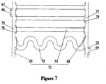
- the plurality of large-capacity tubular containers 60 in the large-scale flowing water tank 54 are distributed into several groups of row tubes 74, and the manifolds 53 are placed on both sides of each groups of row tubes 74; each of large-capacity tubular container 60 arranged in a form of row tubes 74 has two ends equipped with an inlet 76 and an outlet 77; the manifold 53 communicated with the inlets 76 of the large-capacity tubular containers 60 in a group is intake manifold 65, and the manifold 53 communicated with the outlets 77 of the large-capacity tubular containers 60 in a group is exhaust manifold 68; the inlet 76 of the large-capacity tubular container 60 is equipped with an inlet valve 78, and the outlet 77 of the large-capacity tubular container 60 is equipped with an outlet valve 79; the intake manifold 65 is equipped with a manifold inlet 66 and a manifold inlet valve 67, and the exhaust manifold 68 is equipped
- the design volume and pressure of the large-capacity tubular container 60 are respectively larger and higher than the design volume and pressure of the air storage pipe 1; when the capacity of one row tube 74 is not sufficient to meet the design requirement, because it must guarantee that the pipe wall can bear high pressure without diverging the pipe diameter to expand the capacity, while the pipe length can be extended to meet the design requirement for expanding the capacity, then a serpentine pipe 75, i.e., a pipe circuitously extending many times in the spreading plane of the row tube 74, can replace the row tube 74 arranged between the intake manifold 65 and the exhaust manifold 68, and the serpentine pipe 75 is also connected with the intake manifold 65 and the exhaust manifold 68 via its inlet, inlet valve, outlet and outlet valve at its two ends, respectively.
- a serpentine pipe 75 i.e., a pipe circuitously extending many times in the spreading plane of the row tube 74, can replace the row tube 74 arranged between the intake manifold 65 and the exhaust manifold 68,
- each row tube 74 or serpentine pipe 75 is equivalent to a large-capacity tubular container 60, namely a relatively independent compressed air production and storage unit; in the presence of multiple row tubes 74 and/or serpentine pipes 75, equivalent to multiple large-capacity tubular containers 60, they can be respectively referred to in sequence as a large-capacity tubular container A 62, a large-capacity tubular container B 63, a large-capacity tubular container C 64, etc., and the multiple large-capacity tubular containers 60 can also be arranged in other forms in the large-scale flowing water tank 54, e.g., they can be communicated and arranged between the spiral inlet manifolds and outlet manifolds in a cylindrical water tank.
- the large-scale flowing water tank 54 is provided with a water inlet 55 for the inflow of cooling water 58 and a water outlet 56 for the outflow of hot water 59, which is communicated with underground buried insulating pipework 57 in a central heating system.
- An air compressor discharge port 52 of the high/ultra-high pressure air compressor 50 can be detachably connected with the manifold inlet 66, a motor 51 of the high/ultrahigh pressure air compressor 50 works by means of electric energy including night off-peak electricity and wind power unlikely to be stored, and air is compressed and charged to each of large-capacity tubular containers 60 via the manifold inlet 66; heat exchange occurs between mass heat accompanied in the production process of a large amount of compressed air in the large-capacity tubular containers 60 and the cooling water 58 flowing in the large-scale flowing water tank 54, while the cooling water 58 is heated into hot water 59, which then flows out to collect in the underground buried insulating pipework 57 for central heating.
- the large amount of compressed air produced in the large-capacity tubular containers 60 can be stored therein, and the manifold outlet 69 can be detachably connected with the air reception pipe 3 of the air storage pipes 1 in the air tank 9 to compress and charge the compressed air from the large-capacity tubular containers 60 to the air storage pipes 1 in the air tank 9 when necessary.
- the large boiler-type pressure vessel 49 can be arranged on or under the ground, , in a large ship, in a vehicle such as a truck or train, and in a large transport airplane, wherein before the large boiler-type pressure vessels 49 arranged in the vehicle or the large transport airplane is hoisted or started, water stored in the large-scale flowing water tank 54 can be emptied, while the shell of the large-scale flowing water tank 54 can be removed, instead, a compact and light protective housing covers the large-capacity tubular containers 60, referred to as a compressed air container (not shown in the figures), thereby facilitating transportation, and charging compressed air to the air storage pipes 1 of the air tank 9 of the compressed air jet engines 14 arranged in the moving carrier such as the airplane, rocket, train, submarine or the like.
- a compact and light protective housing covers the large-capacity tubular containers 60, referred to as a compressed air container (not shown in the figures), thereby facilitating transportation, and charging compressed air to the air storage pipes 1 of the air tank 9 of the compressed air
- the compressed air container is arranged in the large transport airplane as an aerial compressed air supply airplane, and can charge the compressed air to other airplane equipped with the compressed air jet engines 14 serving as an aerial compressed air receive airplane in the air;
- the manifold outlet 69 in the compressed air container borne by the aerial compressed air supply airplane extends out to the back of the airplane in a tubular shape and the tail end is of an umbrella-shaped taper sleeve
- a telescopic air reception exploring pipe (not shown in the figures) is installed on the head of the aerial compressed air receive airplane and connected with the air reception pipe 3 of the air storage pipes 1 in the air tank 9, then after the aerial compressed air receive airplane and the aerial compressed air supply airplane "rendezvous ", the telescopic air reception exploring pipe is connected and automatically locked with the umbrella-shaped taper sleeve are connected and automatically locked with each other, the air passage is automatically formed, "docking" is thus accomplished, the aerial compressed air supply airplane begins “supply air” to the aerial compressed air receive airplane in the air, and then two airplanes
- the compressed air jet engines 14 can be arranged in the moving carrier of aviation, aerospace, navigation and ground vehicles such as the airplane, rocket, submarine, train or the like.
- the main air engine 41, the first auxiliary air engine 31, the second auxiliary air engine 42, the third auxiliary air engine 44, the fourth auxiliary air engine 46 and the fifth auxiliary air engine 47 can be selectively used or combined with the traditional technology engines: (1) the first auxiliary air engine 31 and the second auxiliary air engine 42 are used for reducing the air resistance of the airplane flying in the air and the sliding friction between the airplane and air, and thus are favorable for acceleration and energy conservation of the airplane; (2) the third auxiliary air engine 44 and the fourth auxiliary air engine 46 can be used for short-distance/vertical take-off of the airplane; the third auxiliary air engine 44, the fourth auxiliary air engine 46 and the fifth auxiliary air engine 47 can be used for short-distance/vertical landing of the airplane; the third auxiliary air engine 44, the fourth auxiliary air engine 46 and the fifth auxiliary air engine 47 are arranged at the functional positions, e.g., in the front of the airplane wings, below the airplane fuselage, at the tail of the airplane, etc.
- the main air engine 41 fixedly, or movably i.e. these engines at ordinary times and during flight are collected inside the wings and/or the body of the airplane to reduce exposed movable components, only during short-distance/vertical take-off and landing of the airplane they stretch out to the above functional positions and are started; (3) compressed air supplying in the air can be carried out if necessary; (4) the backup electric heater 15 can be started when the pressure of the compressed air in the air storage pipes 1 is relatively low due to overworking for some reasons, to maintain the power of the compressed air jet engines 14 for a period of time; (5) if necessary, e.g., when the main air engine 41 has failure, the power of the third auxiliary air engine 44 can be increased to maintain the flight for a period of time; (6) in emergency circumstances, the third auxiliary air engine 44, the fourth auxiliary air engine 46 and the fifth auxiliary air engine 47 are matched with each other and collaboratively work, so that the airplane safely performs short-distance/vertical landing on an open area; (7) moreover
- the main air engine 41, the first auxiliary air engine 31 and the second auxiliary air engine 42 can be arranged on a rocket, the design pressure of the compressed air in the expansion chamber 18 of the main air engine 41 can be obviously ⁇ 20MPa, higher than the maximum pressure of fuel gas in the combustion chamber of the rocket, and the main air engine 41 is light and simple in structure , also favorable for reducing the rocket's "mass ratio" ; the first auxiliary air engine 31 and the second auxiliary air engine 42 are favorable for reducing air resistance and sliding friction with air before the rocket flies out of the atmosphere, making the rocket improving speed and energy-saving; moreover, the main air engine 41, the first auxiliary air engine 31 and the second auxiliary air engine 42 can apply a thrust to forward movement of the rocket.
- the main air engine 41, the first auxiliary air engine 31 and the second auxiliary air engine 42, or a selective combination of them and a traditional technology engine, can be configured on a submarine;
- the first auxiliary air engine 31 is used for blowing away and sweeping off seawater in front of the submarine head, to form a conical low-pressure area 40 (even a vacuum area) in front of the submarine head;
- the second auxiliary air engine 42 are used for blowing away and sweeping off seawater close to the submarine body, to form a low-pressure air layer around the submarine body, so that the submarine in high pressure of seawater runs as in low-pressure air, the resistance of the seawater and the sliding friction between the submarine body and the seawater are reduced favorably, so that the submarine is speed-increasing, energy-saving and silent;
- the main air engine 41, the first auxiliary air engine 31 and the second auxiliary air engine 42 can apply a thrust to forward movement of the submarine.
- the main air engine 41, the first auxiliary air engine 31 and the second auxiliary air engine 42, or a selective combination of them and a traditional technology engine, can be configured on a train;
- the first auxiliary air engine 31 is used for forming a conical low-pressure area 40 (even a vacuum area) in front of the train head, reducing the air resistance favorably, so that the train can increase speed and be energy-saving;
- the nozzles of the plurality of second auxiliary air engines 42 eject high-speed airflow to the back of the train (not shown in the figures), to form a low-pressure air layer around the train body, thereby reducing the sliding friction resistance with the air when the train runs forward;
- the plurality of second auxiliary air engine 42 are arranged in front of the airfoil protruding structures and eject high-speed airflow to the surface of the rear train body, including the surfaces of the airfoil protruding structures, the upper surfaces of the airf
- the output pressure of ultrahigh-pressure air compressors has reached >100MPa, such as, the pressure p of ultrahigh-pressure vessels (Code U) among the pressure vessels is not lower than 100MPa (p ⁇ 100MPa), all far higher than 20MPa.
- the high/ultrahigh-pressure compressed air is appropriately heated by the intake pipe electric heater 29 and the expansion chamber wall electric heater 30 during injection from the air storage pipe 1 to the expansion chamber 18 via the intake pipe 17, thus conducive for air-expansion to do work with higher thrust.
- Safety codes have been formulated for pressure vessels as a mature industry, defining that the legal working pressure is less than 40% of the rupture pressure of an air storage device, and that safety is reliable at 2.5 (i.e., the ratio of ultimate stress to allowable stress is 2.5);
- the university textbook explicitly states the common characteristics of pneumatic transmissions using compressed air as a working medium: the pneumatic transmissions are fast in action, quick in response and strong in working environment adaptability, particularly capable to work safely and reliably under the severe conditions of high temperature difference, flammable and explosive, much dust, vibration and the like, and have the advantages in fire proofing, explosion protection, energy conservation, high efficiency and no pollution among others.
- the pressure vessels are often made of high-pressure resistant and lightweight carbon fibers, which are brittle and under ultrahigh pressure can be split, without producing any shrapnel, at most resulting in the situation that the shell made up of them is "broken" to let compressed air leak, thus avoiding the dangerous situations for fragments and high-pressure gas to splash, so that the safety is also relatively good.
- valve sealing technology is more reliable with the development of pneumatic transmission technology, and those skilled in the art know a comparison that the air leak rate of a compressed air storage device is lower than the electricity gradually depleted rate of a storage battery even in the case without using electricity as the time extends. 4) Reducing the running resistance of the moving carrier, increasing its speed limit, saving energy, improving the lift force of airplane wings, and favorable for short-distance or vertical take-off/landing.
- the de Laval nozzle invented by the Swede Gustav de Laval is recognized as a "flow rate increaser", and is widely applied as a nozzle of a rocket engine; in the present invention, the de Laval nozzle as mentioned above also plays a role of a "flow rate increaser", making the nozzle of the air engine 16 ejects high-speed airflow 24.
- first auxiliary air engine 31 the second auxiliary air engines and the third auxiliary air engines 44 are additionally explained in brief:
- the air resistance borne by the first auxiliary air engine 31 with the raindrop shape 43 is analyzed: (1) the air drag coefficient is also referred to as an wind resistance coefficient, with its magnitude related to the shape of the object, while the raindrop shape has minimum wind resistance coefficient; (2) the cross sectional area (the windward area) of the first auxiliary air engine 31 with the raindrop shape 43 can be small, only several tenths to even several hundredths of the moving carrier head 32; and (3) the air resistance is related to air elasticity due to the air in front of the moving object compressed when the moving object runs, because the conical low-pressure area 40 outside surface, namely the conical side, is the high-speed airflow 24 ejected from the first auxiliary air engine 31 with the raindrop shape 43, and the flow rate of the high-speed airflow 24 is extremely high, always much higher than the velocity of the moving carrier, so that the air in front of the raindrop-shaped first auxiliary air engine 31 is not compressed, but "pulled" by the high-speed airflow 24 to flow backward
- the air resistance borne by the moving carrier in air is proportional to the square of velocity; it is reported that the air resistance is proportional to the cube of velocity when the velocity reaches 400-600m/s; and the air resistance may be directly proportional to the high power of velocity under the condition of higher velocity.
- how to reduce the air resistance for increasingly high-speed aeronautical and astronautic (before flying out of the atmosphere) airplanes is a non-negligible issue, and applying the first auxiliary air engine 31 to high-speed airplanes and rockets is particularly significant.
- sliding friction or kinetic friction
- the second auxiliary air engine nozzles eject high-speed airflow backward relatively close and parallel to the surface of the submarine body (not shown in the figures), covering the surface, the flow rate is high while the pressure (the normal force) on the surface is low, and the high-speed airflow can blow away and sweep off the seawater close to the submarine body to form a low-pressure air layer around it, thus reducing the sliding friction resistance with the surrounding seawater when the submarine runs forward; and the second auxiliary air engines ejecting air backward also applies a certain thrust to the running of the submarine.
- This embodiment describes an operating method of the system using compressed air as force source, including the following steps: Step 1: air is compressed and charged to the large boiler-type pressure vessel 49 by the high/ultrahigh-pressure air compressor 50.
- the manifold inlet valves 67 as well as all of the inlet valves 78 and the outlet valves 79 of the large-capacity tubular containers are opened, and the manifold outlet valves 70 are closed.
- the motor 51 utilizes night off-peak electricity or power not easy to store, such as wind power, solar energy and the like, and the high/ultrahigh-pressure air compressor 50 pressurizes and charges air into the intake manifolds 65, all the large-capacity tubular containers 60 and the exhaust manifolds 68 arranged in the large-scale flowing water tank 54 via the air compressor discharge port 52, the manifold inlet 66 and the manifold inlet valve 67 thereof, all the large-capacity tubular vessel inlets 76 and the opened inlet valves 78 thereof as well as all the large-capacity tubular vessel outlets 77 and the opened outlet valves 79 thereof.
- the controller controls the pressure and quantity of air charged from the air compressor discharge port 52 to adapt to the water flow rates of cooling water 58 flowing in from the water inlet 55 of the large-scale flowing water tank 54 and hot water 59 flowing out of the water outlet 56, so that the heat by-produced during the production process of compressed air in the intake manifolds 65, all the large-capacity tubular containers 60 and the exhaust manifolds 68 is taken away by the cooling water 58 in time, which is heated to become hot water 59 with appropriate temperature, timely flowing out of the water outlet 56 and arriving at the underground directly-buried heat preservation pipe 57 for central heating, until a large amount of compressed air still basically kept at normal temperature in the intake manifolds 65, all the large-capacity tubular containers 60 and the exhaust manifolds 68 reaches the designed high pressure, and the compressed air is then stored for later use;
- Step 2 air is charged to the air tank 9 by the large boiler-type pressure vessel 49.
- the manifold inlet valves 67 and the inlet valves 78 of all the large-capacity tubular containers 60 are closed, only one of the outlet valves 79 of all the large-capacity tubular containers 60 is separately orderly opened while the rest outlet valves 79 are closed, and the manifold outlet valves 70 are opened;
- the manifold outlet 69 is connected with the air reception pipe 3 shared by the air storage pipes 1 in the air tank 9, and only one of the intake valves 5 of the air storage pipes 1 in the air tank 9 is separately opened in order while the rest intake valves 5 are closed;
- the controller controls the compressed air to be charged to an air storage pipe 1 orderly from the opened outlet valve 79 of a large-capacity tubular container 60 via the opened manifold outlet valve 70, the manifold outlet 69, the air reception pipe 3 shared by the air storage pipes 1 in the air tank 9 and a opened air storage pipe intake valve 5,...
- the compressed air is input to the air storage pipe A 10 from large-capacity tubular container A 62, the intake valve 5 of the air storage pipe A 10 is closed when it is full of the compressed air reaching the design requirement pressure, then the intake valve 5 of the air storage pipe B 11 is opened, the compressed air is input to the air storage pipe B 11 from the large-capacity tubular container A 62 ....
- the controller controls the flow rate and the velocity of the compressed air delivered from the large-capacity tubular containers 60 to the air storage pipes 1, so that in the process, the air pressure in the air storage pipes 1 stably rises to the design requirement, the warming and cooling trends are relatively balanced, and the air temperature is basically stable.
- Step 3 the air tank 9 delivers air to the air engine 16.
- the intake valves 5 of all the air storage pipes 1 in the air tank 9 are closed, and one or several of exhaust valves 6 of the air storage pipes 1 in the air tank 9 are separately opened in order while the rest exhaust valves 6 are closed; the controller controls the compressed air to be delivered orderly from the opened exhaust valves 6 of one or several air storage pipes 1 and the air delivery pipe 8 to the intake pipe 17 connected to the air delivery pipe 8, and then the compressed air is injected into the expansion chamber 18 via the air injection vent 25 installed at the expansion chamber head 27 and the air injection adjuster 26.
- the diameter of the intake pipe 17 is smaller than that of the air storage pipes 1, the intake pipe electric heater 29 and the expansion chamber wall electric heater 30 work, the compressed air entering the expansion chamber 18 is appropriately heated to keep higher pressure, then the compressed air flows to the de Laval nozzle convergent section 20 integrally connected with the end of the expansion chamber 18 under high pressure, passes through the de Laval nozzle throat 21 and is ejected from the de Laval nozzle divergent section 22, the air flow is greatly accelerated to produce a huge thrust, and the high-speed airflow 24 also causes the relevant regional aerodynamic changes.
Landscapes
- Engineering & Computer Science (AREA)
- Chemical & Material Sciences (AREA)
- Combustion & Propulsion (AREA)
- Aviation & Aerospace Engineering (AREA)
- Remote Sensing (AREA)
- Mechanical Engineering (AREA)
- General Engineering & Computer Science (AREA)
- Radar, Positioning & Navigation (AREA)
- Transportation (AREA)
- Jet Pumps And Other Pumps (AREA)
Claims (9)
- System zur Verwendung von Druckluft als eine Kraftquelle, wobei das System Druckluftstrahltriebwerke (14) aufweist, die Druckluft mit Hoch- / Ultrahochdruck als ein Strahlarbeitsmedium, eine Erzeugungs- / Zufuhrvorrichtung (48) für Druckluft und eine Steuerung verwenden;wobei die Druckluftstrahltriebwerke (14) zur Ausrüstung auf einem sich bewegenden Träger geeignet sind und einen Lufttank (9) und Luftmotoren (16) aufweisen; wobei der Lufttank (9) ein Druckluftspeicherbehälter ist, der eine Vielzahl an Luftspeicherrohren (1) enthält, um die für die Luftmotoren (16) benötigte Druckluft zu speichern und zuzuführen; wobei die Luftmotoren (16) einen Hauptluftmotor (41) und eine Vielzahl an Hilfsluftmotoren aufweisen; wobei der Hauptluftmotor (41) so angeordnet ist, dass er den Drucklufteintrag aus den Luftspeicherrohren (1) als ein Strahlarbeitsmedium zum Aufbringen eines Schubes auf den sich bewegenden Träger verwendet, der sich vorwärts bewegt; wobei die Vielzahl der Hilfsluftmotoren, die einen ersten Hilfsluftmotor (31), einen zweiten Hilfsluftmotor (42), einen dritten Hilfsluftmotor (44), einen vierten Hilfsluftmotor (46) und einen fünften Hilfsluftmotor (47) aufweist, jeweils um den sich bewegenden Träger herum angeordnet ist, um den Drucklufteintrag aus den Luftspeicherrohren (1) als ein Strahlarbeitsmedium in Abstimmung mit dem Hauptluftmotor (41) zum Drücken des sich bewegenden Trägers in Richtung auf eine Zielrichtung zu verwenden;wobei die Erzeugungs- / Zufuhrvorrichtung (48) für Druckluft, einen Luftkompressor (50) mit Hoch- / Ultrahochdruck und einen großen Druckbehälter vom Kesseltyp (49) aufweist; wobei der Arbeitsdruck des Luftkompressors (50) mit Hoch-/ Ultrahochdruck nahe bei oder gleich 100 MPa liegt, um die Luft unter der Steuerung der Steuerung unter Druck zu setzen und in den großen Druckbehälter vom Kesseltyp (49) einzublasen; wobei der große Druckbehälter vom Kesseltyp (49) verwendet wird, um zum Druckbeaufschlagen und Einblasen der Druckluft in die Vielzahl der Luftspeicherrohre (1) die Druckluft zu erzeugen und zu speichern;wobei die Steuerung verwendet wird, um das Öffnen und das Schließen des Hauptluftmotors (41), des ersten Hilfsluftmotors (31), des zweiten Hilfsluftmotors (42), des dritten Hilfsluftmotors (44) und des vierten Hilfsluftmotors (46) und des fünften Hilfsluftmotors (47) zu steuern, um den sich bewegenden Trägers in Richtung auf die Zielrichtung zu drücken.
- System zur Verwendung von Druckluft als die Kraftquelle nach Anspruch 1, wobei jeweils der Hauptluftmotor (41), der erste Hilfsluftmotor (31), der zweite Hilfsluftmotor (42), der dritte Hilfsluftmotor (44), der vierte Hilfsluftmotor (46) und der fünfte Hilfsluftmotor (47) ein hochdruckbeständiges Ansaugrohr aus einem leichteren Material (17), eine Expansionskammer (18) und eine De-Laval-Düse (19) aufweisen;wobei das Ansaugrohr (17) mit dem Luftspeicherrohr (1) und der Expansionskammer (18) verbunden ist und es von einer elektrischen Heizung (29) des Ansaugrohrs umgeben ist, um die Druckluft zu erwärmen, um den Luftdruck in dem Ansaugrohr (17) zu erhöhen; wobei die Druckluft in dem Luftspeicherrohr (1) durch eine Luftinjektionsentlüftung (25) des Ansaugrohrs (17) in die Expansionskammer (18) eingespritzt wird;wobei die Expansionskammerwand (28) der Expansionskammer (18) mit einem Luftinjektionseinsteller (26) versehen ist, um die Menge der Druckluft bei einem festgelegten Druck zu modulieren, der von dem Ansaugrohr (17) in die Expansionskammer (18) eingespritzt wird, um den Druck in der Expansionskammer (18) auf dem eingestellten Druck zu halten; wobei sich eine elektrische Wandheizung (30) der Expansionskammer um die Expansionskammer (18) herum befindet, um die in die Expansionskammer (18) eintretende Druckluft zur Druckbeaufschlagung zu erwärmen;wobei die Querschnittsfläche der De-Laval-Düse (19) zuerst konvergiert ist und dann divergiert ist; wobei die Rückseite der Expansionskammer (18) einstückig mit einem Konvergenzabschnitt (20) der De-Laval-Düse verbunden ist; wobei die Druckluft aus der Expansionskammer (18) unter Druck beschleunigt wird, um durch den Konvergenzabschnitt (20) der De-Laval-Düse, einen Hals (21) der De-Laval-Düse und einen Divergenzabschnitt (22) der De-Laval-Düse schließlich zu einem Luftstrom (24) hoher Geschwindigkeit zu gelangen, der aus einer Öffnung (23) der De-Laval-Düse ausgestoßen wird.
- System zur Verwendung von Druckluft als die Kraftquelle nach Anspruch 2, wobei der erste Hilfsluftmotor (31) an der Vorderseite des beweglichen Trägerkopfes (32) angebracht ist; wobei die Querschnittsfläche des ersten Hilfsluftmotors (31) kleiner als die des entsprechenden beweglichen Trägerkopfes (32) ist; wobei der erste Hilfsluftmotor (31) ein erstes Ansaugrohr (17a), eine erste Expansionskammer (18a) und eine erste De-Laval-Düse (19a) als auch eine feste Rohrstruktur (33) aufweist, durch die der erste Hilfsluftmotor (33a) an der Vorderseite des beweglichen Trägerkopfes (32) befestigt ist; wobei das erste Ansaugrohr (17a) innerhalb der festen Rohrstruktur (33) angeordnet ist und von der festen Rohrstruktur (33) getragen wird; wobei die Rückseite der ersten Expansionskammer (18a) einstückig mit dem Konvergenzabschnitt (20a) der ersten De-Laval-Düse verbunden ist; wobei die gesamte erste De-Laval-Düse (19a) eine De-Laval-düsenartige Struktur von vorne nach hinten aufweist; wobei das erste Ansaugrohr (17a) zusammen mit der festen Rohrstruktur (33), die sich von dem sich bewegenden Trägerkopf (32) nach vorne erstreckt und durch eine erste Hilfsluftmotordüse (39), einen Divergenzabschnitt (22a) der ersten De-Laval-Düse, einen ersten Hals (21a) der De-Laval-Düse, den Konvergenzabschnitt (20a) der ersten DeLaval-Düse und die erste Expansionskammer (18a) nacheinander zusammen mit dem axialen Zentrum des ersten Hilfsluftmotors (31) durchgeht, um mit einer Innenwand (37) des ersten Expansionskammerkopfes fest verbunden zu sein, an der eine erste Luftinjektionsentlüftung und ein Luftinjektionseinsteller (35) angebracht sind; wobei die Druckluft in der ersten Expansionskammer (18a) unter dem Druck beschleunigt wird, um durch den Konvergenzabschnitt (20a) der ersten De-Laval-Düse, den Düsenhals (21a) der ersten De-Laval-Düse und schließlich den Spalt zwischen dem Divergenzabschnitt (22a) der ersten De-Laval-Düse und einem konisch verbreiterten Abschnitt (33a) der festen röhrenförmigen Struktur (33) zu gelangen, der entlang einer konischen Seite rückwärts um den beweglichen Trägerkopf (32) ausgeworfen wird, wobei die Generatrix der konischen Seite der Verbindungsleitung (32a) von dem ersten Hals (21a) der De-Laval-Düse zu dem Umfang des beweglichen Trägerkopfes (32) entspricht, um einen konischen Niederdruckbereich (40) vor dem beweglichen Trägerkopf (32) zu bilden, um den Luftwiderstand oder den Meerwasserwiderstand zu verringern, wenn sich der sich bewegende Träger vorwärts bewegt; wobei der erste Hilfsluftmotor (31) auch verwendet wird, um einen bestimmten Schub für die Vorwärtsbewegung des sich bewegenden Trägers aufzubringen.
- System zur Verwendung von Druckluft als die Kraftquelle nach Anspruch 3, wobei mehrere zweite Hilfsluftmotoren (42) um den sich bewegenden Träger herum angeordnet sind, wobei dessen Düsen in Richtung auf die Rückseite des sich bewegenden Trägers zeigen, um einen Luftstrom hoher Geschwindigkeit zum Aufbringen eines Schubes zu dem sich vorwärts bewegenden Träger auszustoßen; wobei darüber hinaus der Luftstrom hoher Geschwindigkeit, der von den Düsen der zweiten Hilfsluftmotoren (42) ausgestoßen wird, parallel und nahe an der Oberfläche des sich bewegenden Trägers ist, so dass eine Niederdruckluftschicht um den sich bewegenden Träger herum gebildet wird, wodurch der Widerstand der Gleitreibung zwischen dem sich bewegenden Träger und seiner Umgebung verringert wird, wenn er sich vorwärts bewegt.
- System zur Verwendung von Druckluft als die Kraftquelle nach Anspruch 1, wobei der bewegliche Träger zur Ausstattung mit einem oder mehreren Lufttanks (9) geeignet ist, wobei in jedem der Lufttanks (9) sich mehrere Luftspeicherrohre (1) befinden, die eine lange röhrenförmige Struktur mit einer zylindrischen Luftspeicherrohrwand (2) aus hochdruckbeständigen und leichteren Materialien aufweisen; wobei eine Vielzahl an Luftspeicherrohren (1) gebündelt und parallel zu ihrem gesamten Querschnitt als eine pflaumenartige Struktur angeordnet ist; wobei jedes der Luftspeicherrohre (1) mit einem Einlassventil (5) und einem Auslassventil (6) versehen ist, deren Öffnen und Schließen individuell von der Steuerung gesteuert werden;wobei um die Luftspeicherrohre (1) herum elektrische Notheizungen angeordnet sind, um zu starten, wenn das Druckluftstrahltriebwerk (14) aus irgendeinem Grund überlastet ist und wenn der Druckluftdruck in allen Luftspeicherrohren (1) niedriger als eine vorbestimmte Grenze ist;wobei die einen Enden der Luftspeicherrohre (1), die mit einem Luftempfangs-Mehrwegrohr (4) verbunden sind, in ein Luftempfangsrohr (3) zusammenlaufen; wobei die andere Enden der Luftspeicherrohren (1), die mit einem Luftzufuhr-Mehrwegrohr (7) verbunden sind, zu einem Luftzufuhrrohr (8) zusammenlaufen; wobei die Luftspeicherrohre (1) durch das Luftzufuhrrohr (8) mit dem Ansaugrohr (17) verbunden sind;wobei das Luftaufnahmerohr (3) zum Aufnehmen der Druckluft verwendet wird, die unter Druck steht und die aus dem großen Kesseldruckbehälter (49) eingeblasen wird.
- System zur Verwendung von Druckluft als die Kraftquelle nach Anspruch 1, wobei der große Druckbehälter vom Kesseltyp (49) zum Komprimieren und Laden von Luft zu den Luftspeicherrohren (1) in einem Lufttank (9), der einen Fließwassertank (54) mit einem großen Druckbehälter und eine Vielzahl an Rohrbehältern (60) mit großer Kapazität und Verteiler (53) enthält, die in dem Wassertank angeordnet sind;wobei eine Vielzahl an Rohrbehältern (60) mit großer Kapazität in mehrere Gruppen von Reihenrohren (74) verteilt sind, und die Verteiler (53) auf beiden Seiten jeder Gruppe von Reihenrohren (74) angeordnet sind; wobei jeder Rohrbehälter (60) mit großer Kapazität in Form von Reihenrohren (74) angeordnet ist und zwei Enden aufweist, die mit einem Einlass (76) und einem Auslass (77) ausgestattet sind; wobei der Verteiler (53) mit den Einlässen (76) der Rohrbehälter mit großer Kapazität (60) in einer Gruppe kommuniziert, die ein Ansaugverteiler (65) ist, und der Verteiler (53) mit den Auslässen (77) der Rohrbehälter (60) mit großer Kapazität in einer Gruppe kommuniziert, die ein Auslassverteiler (68) ist; wobei der Einlass (76) des Rohrbehälters (60) mit großer Kapazität mit einem Einlassventil (78) versehen ist, und der Auslass (77) des Rohrbehälters (60) mit großer Kapazität mit einem Auslassventil (79) versehen ist; wobei der Ansaugverteiler (65) mit einem Verteilereinlass (66) und einem Verteilereinlassventil (67) versehen ist und der Auslassverteiler (68) mit einem Verteilerauslass (69) und einem Verteilerauslassventil (70) versehen ist;wobei das Auslegungsvolumen und der Druck des Rohrbehälters (60) mit großer Kapazität jeweils größer bzw. höher als die der Luftspeicherrohre (1) sind; wobei einige röhrenförmige Behälter (60) mit großer Kapazität Serpentinenrohre (75) in einer röhrenförmigen Struktur sind, die sich kreisförmig viele Male innerhalb der Ebene der Reihenrohre (74) erstrecken;wobei die Reihenrohre (74), die sich in einer Ebene ausbreiten, sowie die Ansaugverteiler (65) und die Auslassverteiler (68) auf den beiden Seiten der Reihenrohre (74) eine Rohrbehälterebene (73) mit großer Kapazität bilden; wobei in einem Fließwassertank (54) großen Ausmaßes sich mehrere Rohrbehälterebenen mit großer Kapazität (73) befinden, wobei die Ansaugverteiler (65) dieser Rohrbehälterebenen mit großer Kapazität (73) über mehrere Kommunikationsrohre des Ansaugverteilers (71) miteinander verbunden sind und einen Verteilereinlass (66) teilen, der mit einem entsprechenden Verteilereinlassventil (67) versehen ist, und der Auslassverteiler (68) dieser Rohrbehälterebenen (73) mit großer Kapazität über mehrere Auslassverteiler-Kommunikationsrohre (72) verbunden ist und einen Verteilerauslass (69) teilt, der mit einem entsprechenden Verteilerauslassventil (70) versehen ist;wobei der Fließwassertank (54) großen Ausmaßes mit einem Wassereinlass (55) für den Zufluss von Kühlwasser (58) und einem Wasserauslass (56) für den Abfluss von Warmwasser (59) versehen ist, der mit den im Untergrund vergrabenen isolierenden Rohrleitungen (57) in einem Zentralheizungssystem kommuniziert;wobei eine Luftkompressor-Auslassöffnung (52) des Luftkompressors (50) mit Hoch- / Ultrahochdruck abnehmbar mit dem Verteilereinlass (66) verbunden ist, um die Luft unter Druck zu setzen und in den Rohrbehälter mit großer Kapazität (60) einzublasen.
- Flugzeug, welches das System zur Verwendung von Druckluft als die Kraftquelle nach einem der Ansprüche 1 bis 6 aufweist, wobei der erste Hilfsluftmotor (31) vor dem Flugzeugkopf angeordnet ist, wobei der zweite Hilfsluftmotor (42) auf der Umfangsseite des Flugzeugrumpfs angeordnet ist und wobei eine Vielzahl an dritten Hilfsluftmotoren (44) symmetrisch vor den Tragflächen auf beiden Seiten des Flugzeugs angeordnet sind; wobei die Düsen der dritten Hilfsluftmotoren (44) einen Luftstrom (24) hoher Geschwindigkeit zurück in Richtung auf die Flügel ausstoßen, und die Richtung des Luftstroms hoher Geschwindigkeit dieselbe wie die Richtung des Luftstroms in Richtung auf die Flügel ist, während das Flugzeug zu einem Start rollt; wobei die dritten Hilfsluftmotoren (44) verwendet werden, um die Auftriebskraft der Flugzeugflügel zu erhöhen, um einen Start / eine Landung mit kurzer Reichweite oder vertikaler Reichweite zu ermöglichen, sowie um den Schub für das sich vorwärts bewegende Flugzeug entsprechend den Reaktionskräften des Luftstroms aufzubringen, der aus den Düsen der dritten Hilfsluftmotoren (44) ausgestoßen wird.
- Flugzeug nach Anspruch 7, wobei der vierte Hilfsluftmotor (46) unter dem Flugzeugrumpf angeordnet ist, um den Luftstrom zu der Richtung nach hinten oder vorne unten unter dem Flugzeug auszustoßen, um die Gegenkräfte in Richtung zu der Richtung nach vorne oder nach vorne oben über dem Flugzeug auszuüben; wobei die fünften Hilfslufttriebwerke (47) direkt unter dem Flugzeugheck oder symmetrisch auf beiden Seiten des Hecks angeordnet sind, um einen Luftstrom hoher Geschwindigkeit in die umgekehrte Richtung des Flug des Flugzeugs auszustoßen, um eine Rolle beim Puffern und Abbremsen des Flug des Flugzeugs zu spielen.
- Verfahren zum Betreiben des Systems zur Verwendung von Druckluft als die Kraftquelle nach einem der Ansprüche 1 bis 6, wobei das System ferner ein Luftaufnahmerohr (3), ein Einlassventil (5), ein Luftzufuhrrohr (8), ein Ansaugrohr (17), eine Expansionskammer (18), einen Konvergenzabschnitt (20) der De-Laval-Düse, einen Hals (21) der De-Laval-Düse, einen Divergenzabschnitt (22) der De-Laval-Düse, eine Luftinjektionsentlüftung (25), einen Expansionskammerkopf (27), eine elektrische Heizung (29) des Ansaugrohrs, eine elektrische Wandheizung (30) der Expansionskammer, einen Motor (51), eine Luftkompressor-Auslassöffnung (52), einen Fließwassertank (54) großen Ausmaßes, ein Wassereinlass (55), ein Wasserauslass (56), im Untergrund vergrabenen isolierenden Rohrleitungen (57), ein Verteilereinlass (66), ein Verteilereinlassventil (67), ein Auslassverteiler (68), ein Verteilerauslassventil (70), ein Einlassventil (78) und Auslassventile (79) aufweist, wobei das Verfahren die folgenden Schritte umfasst:Schritt eins: ein Druckbeaufschlagen und ein Einblasen von Luft in den großen Kesseldruckbehälter (49) durch einen Luftkompressor (50) mit Hoch- / Ultrahochdruck; wobei der Kesseldruckbehälter (49) Rohrbehälter mit großer Kapazität (60) aufweist;wobei während dieses Vorgangs das Einlassventil (67) des Verteilers, alle Einlassventile (78) und die Auslassventile (79) der Rohrbehälter (60) mit großer Kapazität geöffnet sind, während die Auslassventile (70) des Verteilers geschlossen sind;wobei der Motor (51) einen Nachtstrom außerhalb der Spitzenzeiten oder einen Strom verwendet, der nicht leicht zu speichern ist, wie zum Beispiel Windkraft, Sonnenenergie und dergleichen, um den Luftkompressor (50) mit Hoch- / Ultrahochdruck zum Druckbeaufschlagen und Einblasen von Luft durch die Kompressorauslassöffnung (52), den Verteilereinlass (66) und sein geöffnetes Verteilereinlassventil (67), alle großen röhrenförmigen Behältereinlässe (76) und deren geöffneten Einlassventile (78) und alle großen röhrenförmigen Behälterauslässe (77) und deren geöffneten Auslassventile (79) in die Ansaugverteiler (65), die sich in dem Fließwassertank (54) großen Ausmaßes befinden, alle Rohrbehälter mit großer Kapazität (60) und die Auslassverteiler (68) anzutreiben;wobei während die Steuerung den Druck und die Menge der Luft steuert, die aus der Luftkompressorauslassöffnung (52) eingefüllt wird, um sich an die Wasserdurchflussraten des Kühlwassers (58), das von dem Wassereinlass (55) fließt, und des Warmwassers (59), das aus dem Wasserauslass (56) des Fließwassertank (54) großen Ausmaßes ausströmt, anzupassen, so dass die Wärme, die bei der Erzeugung der Druckluft in den Ansaugverteilern (65), allen Rohrbehältern (60) mit großer Kapazität und den Auslassverteilern (68) entsteht, rechtzeitig von dem Kühlwasser (58) abtransportiert wird, das erwärmt wird, um das Warmwasser (59) auf eine geeignete Temperatur zu bringen, die zu gegebener Zeit aus dem Wasserauslass (56) zu den im Untergrund vergrabenen isolierenden Rohrleitungen (57) für die Zentralheizung fließt, bis eine große Menge Druckluft in den Ansaugverteilern (65), allen Rohrbehältern mit großer Kapazität (60) und den Auslassverteilern (68) noch vorhanden ist, während es Grunde die normale Temperatur bleibt, er den hohen Druck wie er zum Speichern als Reserve ausgelegt ist erreicht;wobei dann die Verteilereinlassventile (67), alle Einlassventile (78) und die Auslassventile (79) aller Rohrbehälter mit großer Kapazität (60) geschlossen sind, während die Verteilerventilventile (70) geschlossen bleiben;Schritt zwei: ein Einblasen von Luft aus dem großen Kesseldruckbehälter (49) in den Lufttank (9);wobei während dieses Vorgangs die Verteilereinlassventile (67) und die Einlassventile (78) aller Rohrbehälter (60) mit großer Kapazität geschlossen sind, und nur ein einziges der Auslassventile (79) aller Rohrbehälter (60) mit großer Kapazität separat ordnungsgemäß geöffnet ist, aber die übrigen Auslassventile (79) geschlossen sind, während die Auslassventile (70) des Verteilers geöffnet sind; wobei der Verteilerauslass (69) mit dem Luftaufnahmerohr (3) verbunden ist, das von den Luftspeicherrohren (1) in dem Lufttank (9) geteilt wird, während nur ein einziges der Einlassventile (5) der Luftspeicherrohre (1) in dem Lufttank (9) jeweils offen ist und ordentlich ist, während die anderen Einlassventile (5) geschlossen sind;wobei die Steuerung die Druckluft ordnungsgemäß von dem geöffneten Auslassventil (79) des Rohrbehälters mit großer Kapazität (60) über das geöffnete Verteilerauslassventil (70), den Verteilerauslass (69) und das Luftaufnahmerohr (3), das durch die Luftspeicherrohre (1) in dem Lufttank (9) geteilt ist, und ein geöffnetes Luftspeicherrohr-Einlassventil (5) steuert, um dieses Luftspeicherrohr (1) zu füllen;wobei während des Vorgangs des Befüllens eines der Luftspeicherrohre (1) nacheinander mit der Druckluft aus dem Rohrbehälter mit großer Kapazität (60), in dem der Luftdruck allmählich abfällt, so dass später, wenn ein Luftspeicherrohr (1) seinerseits gefüllt werden soll, der Luftdruck innerhalb des Rohrbehälters (60) mit großer Kapazität auf den Luftdruck gefallen ist, der gleich dem ist, der allmählich in dem Luftspeicherrohr (1) erhöht wird, um den Rohrbehälter (60) mit großer Kapazität dazu zu bringen, nicht mehr in der Lage zu sein, Luft in das Luftspeicherrohr (1) abzulassen, in dem der Luftdruck noch nicht auf den vorgesehenen Zustand angestiegen ist, wobei dann die Steuerung das Öffnen und das Schließen der Auslassventile (79) der Rohrbehälter (60) mit großer Kapazität und der Einlassventile (5) der Luftspeicherrohre (1) steuert, damit der Rohrbehälter mit großer Kapazität (60) unter einem verringerten Luftdruck die anderen Luftspeicherrohre (1) füllen kann, in die nicht eingeblasen worden ist oder die einen relativ niedrigeren Luftdruck aufweisen, und um die Luftspeicherrohre (1) mit dessen Luftdruck, der durch das Einblasen erhöht worden ist, aber der noch nicht auf den vorgesehenen Zustand angestiegen ist, die Rohrbehälter (60) mit großer Kapazität unter einem anfänglichen oder einem relativ höheren Luftdruck stehen zu haben, um sie zu füllen;wobei während des Vorgangs des Einblasens von Druckluft aus dem Rohrbehälter (60) mit großer Kapazität in die Luftspeicherrohre (1) die Luft in den Luftspeicherrohren (1) mit zunehmendem Luftdruck somit einen Erwärmungstrend aufweist, während der Eintrag der Druckluft aus dem Rohrbehälter (60) mit großer Kapazität in die Luftspeicherrohre (1) mit relativ abnehmendem Luftdruck somit einen Abkühlungstrend aufweist; wobei die Steuerung den Durchfluss und die Geschwindigkeit des Drucklufteintrags aus dem Rohrbehälter (60) mit großer Kapazität in die Luftspeicherrohre (1) so steuert, dass während des Vorgangs der Druck in den Luftspeicherrohren (1) allmählich zu einem bestimmten Zustand erhöht wird, der gleichzeitig die Erwärmungs- und Abkühlungstrends bei einer im Wesentlichen stabilen Temperatur relativ ausgeglichen macht;Schritt drei: ein Einblasen von Luft aus dem Lufttank (9) in den Luftmotor (16);wobei während des Betriebs des Luftmotors (16) alle Einlassventile (5) aller Luftspeicherrohre (1) in dem Lufttank (9) geschlossen sind, und nur eines oder mehrere der Auslassventile (6) aller Luftspeicherrohre (1) in dem Lufttank (9) jeweils offen und ordnungsgemäß geöffnet sind, während die restlichen Auslassventile (6) geschlossen sind; wobei die Steuerung die Drucklufteinspritzung ordnungsgemäß von einem oder mehreren geöffneten Auslassventilen (6) der Luftspeicherrohre (1) und dem Luftzufuhrrohr (8) in das angeschlossene Ansaugrohr (17) und durch die Luftinjektionsentlüftung (25) an dem Expansionskammerkopf (27) und an dem Luftinjektionseinsteller (26) steuert, die in der Expansionskammer (18) angebracht sind;wobei der Durchmesser des Ansaugrohrs (17) kleiner als der des Luftspeicherrohrs (1) ist; wobei während die elektrische Heizung (29) des Ansaugrohrs und die elektrische Heizung (30) der Expansionskammerwand arbeiten, die in die Expansionskammer (18) eintretende Druckluft mäßig erwärmt wird, um einen relativ höheren Druck aufrechtzuerhalten, und sie unter höherem Druck wiederum in den Konvergenzabschnitt (20) der De-Laval-Düse fließt, der mit dem Ende der Expansionskammer (18) verbunden ist, sie dann durch den Hals (21) der De-Laval-Düse und den Divergenzabschnitt (22) der De-Laval-Düse ausgestoßen wird, wodurch sie stark beschleunigt wird, um einen großen Schub zu erzeugen; wobei ein solcher ausgestoßener Luftstrom (24) mit hoher Geschwindigkeit sich auch auf die Änderungen der relevanten lokalen Aerodynamik auswirkt.
Applications Claiming Priority (2)
| Application Number | Priority Date | Filing Date | Title |
|---|---|---|---|
| CN201620169386.3U CN205559070U (zh) | 2016-03-04 | 2016-03-04 | 以压缩空气为施力源的系统及飞机 |
| PCT/SE2017/000005 WO2017151029A1 (en) | 2016-03-04 | 2017-01-16 | A system of using compressed air as a force source and method thereof; airplane |
Publications (3)
| Publication Number | Publication Date |
|---|---|
| EP3423716A1 EP3423716A1 (de) | 2019-01-09 |
| EP3423716A4 EP3423716A4 (de) | 2019-11-06 |
| EP3423716B1 true EP3423716B1 (de) | 2021-03-31 |
Family
ID=56817241
Family Applications (1)
| Application Number | Title | Priority Date | Filing Date |
|---|---|---|---|
| EP17760385.9A Active EP3423716B1 (de) | 2016-03-04 | 2017-01-16 | System zur verwendung von druckluft als kraftquelle und verfahren dafür; flugzeug |
Country Status (4)
| Country | Link |
|---|---|
| US (1) | US11149633B2 (de) |
| EP (1) | EP3423716B1 (de) |
| CN (1) | CN205559070U (de) |
| WO (1) | WO2017151029A1 (de) |
Families Citing this family (23)
| Publication number | Priority date | Publication date | Assignee | Title |
|---|---|---|---|---|
| CN105649775B (zh) * | 2016-03-04 | 2017-06-23 | 王力丰 | 以压缩空气为施力源的系统及其方法、飞机 |
| CN205559070U (zh) | 2016-03-04 | 2016-09-07 | 王力丰 | 以压缩空气为施力源的系统及飞机 |
| CN107910934A (zh) * | 2017-12-14 | 2018-04-13 | 李士明 | 能源替代式的以电代油型的自发电飞机 |
| CN109373626B (zh) * | 2018-09-04 | 2021-01-08 | 北京航空航天大学 | 一种基于压缩空气蓄能的高适应能力的空气膨胀制冷系统 |
| WO2020053868A1 (en) * | 2018-09-12 | 2020-03-19 | Ravibabu Meruva | An air inhale tunnel conduit jet propulsion apparatus and method for flying craft |
| US20220219788A1 (en) * | 2019-05-03 | 2022-07-14 | Paha Designs, Llc | Transport vehicle with reduced drag |
| CN110155371B (zh) * | 2019-06-03 | 2021-06-01 | 北京航空航天大学 | 一种充气喷射起飞滑翔回收的火星飞行器及其使用方法 |
| US12024280B2 (en) * | 2019-09-03 | 2024-07-02 | Bae Systems Plc | Vehicle control |
| AU2020342617B2 (en) | 2019-09-03 | 2026-02-12 | Bae Systems Plc | Fluidic control |
| CN110836149A (zh) * | 2019-11-06 | 2020-02-25 | 浙江科技学院 | 一种低可探测性航空发动机 |
| CN110963035B (zh) | 2019-12-18 | 2024-10-01 | 王力丰 | 以压缩空气为动力源的个人飞行器及其运行方法 |
| US12595078B2 (en) * | 2020-01-17 | 2026-04-07 | Addison M. Fischer | Aerospace vehicles |
| GB202003830D0 (en) * | 2020-03-17 | 2020-04-29 | Prescott Matthew Harry | Improvements to the movement of a vehicle, aircraft or vessel |
| CN112357123A (zh) * | 2020-10-30 | 2021-02-12 | 北京空间飞行器总体设计部 | 一种可进行物品转移的喷气式转移装置及方法 |
| CN113060290A (zh) * | 2021-04-29 | 2021-07-02 | 陕西北斗金箭航空科技有限公司 | 一种电动推进器 |
| CN113200141B (zh) * | 2021-05-26 | 2022-05-31 | 西安理工大学 | 一种基于拉瓦管状等离子体吸气式增升装置 |
| CN114103572B (zh) * | 2021-12-30 | 2023-08-22 | 北京国家新能源汽车技术创新中心有限公司 | 一种双涵道混合动力装置、飞行汽车以及控制方法 |
| CN116439057A (zh) * | 2022-01-14 | 2023-07-18 | 陈世雄 | 流体动力造雨装置 |
| CN114729600B (zh) * | 2022-02-15 | 2023-09-19 | 烟台杰瑞石油装备技术有限公司 | 双燃料动力系统及其供气吹扫方法 |
| CN114526173A (zh) * | 2022-02-25 | 2022-05-24 | 中国工程物理研究院总体工程研究所 | 一种具有推力可调功能的冷气喷射型姿态控制系统 |
| CN115346415B (zh) * | 2022-09-05 | 2023-07-25 | 中国航空工业集团公司沈阳空气动力研究所 | 一种沉浸式滑雪模拟系统及其使用方法 |
| CN116573171B (zh) * | 2023-03-10 | 2025-09-19 | 苏州大学 | 一种末端执行器、发动机喉管捕获与释放装置及方法 |
| CN120364128B (zh) * | 2025-06-26 | 2025-09-02 | 中国空气动力研究与发展中心低速空气动力研究所 | 一种飞行器组合射流航向控制舵面 |
Family Cites Families (14)
| Publication number | Priority date | Publication date | Assignee | Title |
|---|---|---|---|---|
| GB919620A (en) * | 1960-12-28 | 1963-02-27 | Short Brothers & Harland Ltd | Improvements in the control systems of vehicles adapted for vertical take-off and landing |
| US3302602A (en) * | 1965-02-26 | 1967-02-07 | Korganoff Alexandre | Submersible vessels |
| US4224790A (en) | 1977-10-11 | 1980-09-30 | Christensen Raymond G | Jet engine |
| US5141173A (en) * | 1991-08-12 | 1992-08-25 | Lay Joachim E | Pressure-jet and ducted fan hybrid electric car |
| US6517026B1 (en) | 2001-09-06 | 2003-02-11 | Leo Smith | Vertical take-off and landing vehicle for land, water and air transport |
| US7673459B2 (en) | 2006-04-05 | 2010-03-09 | General Electric Company | System and method for providing air to a compressor of an aircraft auxiliary gas turbine engine |
| KR20100046754A (ko) * | 2008-10-28 | 2010-05-07 | 문정일 | 선형 램제트 엔진 및 이를 이용한 동축반전 로터 비행체 |
| US8347628B2 (en) | 2009-08-18 | 2013-01-08 | Gerard Henry M | Power generation directly from compressed air for exploiting wind and solar power |
| CN102877983A (zh) | 2011-07-11 | 2013-01-16 | 郑有志 | 军用多级液压喷气式发动机 |
| US8827200B2 (en) * | 2011-09-16 | 2014-09-09 | Bogdan Radu | Flying vehicle |
| JP6373794B2 (ja) * | 2015-05-08 | 2018-08-15 | 株式会社神戸製鋼所 | 圧縮空気貯蔵発電装置及び圧縮空気貯蔵発電方法 |
| CN104948234B (zh) | 2015-05-29 | 2017-07-21 | 王力丰 | 经济利用压缩空气为汽车动力源的系统及其方法 |
| JP6511378B2 (ja) * | 2015-09-29 | 2019-05-15 | 株式会社神戸製鋼所 | 圧縮空気貯蔵発電装置及び圧縮空気貯蔵発電方法 |
| CN205559070U (zh) | 2016-03-04 | 2016-09-07 | 王力丰 | 以压缩空气为施力源的系统及飞机 |
-
2016
- 2016-03-04 CN CN201620169386.3U patent/CN205559070U/zh not_active Withdrawn - After Issue
-
2017
- 2017-01-16 WO PCT/SE2017/000005 patent/WO2017151029A1/en not_active Ceased
- 2017-01-16 US US16/082,195 patent/US11149633B2/en active Active
- 2017-01-16 EP EP17760385.9A patent/EP3423716B1/de active Active
Non-Patent Citations (1)
| Title |
|---|
| None * |
Also Published As
| Publication number | Publication date |
|---|---|
| US20200325820A1 (en) | 2020-10-15 |
| US11149633B2 (en) | 2021-10-19 |
| EP3423716A4 (de) | 2019-11-06 |
| WO2017151029A1 (en) | 2017-09-08 |
| EP3423716A1 (de) | 2019-01-09 |
| CN205559070U (zh) | 2016-09-07 |
Similar Documents
| Publication | Publication Date | Title |
|---|---|---|
| US11149633B2 (en) | System of using compressed air as a force source and method thereof; airplane | |
| CN105649775B (zh) | 以压缩空气为施力源的系统及其方法、飞机 | |
| US10815935B2 (en) | Throttleable propulsion launch escape systems and devices | |
| US10246200B2 (en) | Centripetal aerodynamic platform spacecraft | |
| EP1163152B1 (de) | System für das tragen und starten einer nutzlast | |
| CN109018445B (zh) | 小卫星运载器 | |
| CN109764774B (zh) | 一种用于模拟火箭返回着陆过程的试验装置 | |
| AU674691B2 (en) | Multipurpose airborne vehicle | |
| US11920543B2 (en) | Rocket propulsion systems and associated methods | |
| CN119013190A (zh) | 氢优化飞行器架构和操作 | |
| CN102022223A (zh) | 涡流冲压发动机 | |
| RU2609539C1 (ru) | Ракета-носитель, возвращаемая ступень ракеты-носителя и способ ее запуска при возвращении и система вертолетного подхвата возвращаемой ступени | |
| US20250171111A1 (en) | System for cargo transport | |
| RU2164882C1 (ru) | Многоразовая воздушно-космическая система | |
| Mizobata et al. | Conceptual design of flight demonstrator vehicles for the ATREX engines | |
| WO2018138112A1 (en) | A flying craft | |
| CN109335004B (zh) | 一种配置混合动力的微型无人机 | |
| CN106939849A (zh) | 一种气动发动装置及其用途 | |
| WO2020053868A1 (en) | An air inhale tunnel conduit jet propulsion apparatus and method for flying craft | |
| CN109264029A (zh) | 一种运载火箭 | |
| RU2252177C2 (ru) | Способ полета и устройство для его осуществления | |
| Baxter | Aircraft Rocket Motors: With Special Reference to German Developments with Hydrogen Peroxide | |
| Lantz | An efficient system for transportation to and from earth orbit | |
| CN201818392U (zh) | 涡流冲压发动机 | |
| Skoog | Design Improvements for a Reusable Horizontal Takeoff and Landing Aircraft for Use on Mars |
Legal Events
| Date | Code | Title | Description |
|---|---|---|---|
| STAA | Information on the status of an ep patent application or granted ep patent |
Free format text: STATUS: THE INTERNATIONAL PUBLICATION HAS BEEN MADE |
|
| PUAI | Public reference made under article 153(3) epc to a published international application that has entered the european phase |
Free format text: ORIGINAL CODE: 0009012 |
|
| STAA | Information on the status of an ep patent application or granted ep patent |
Free format text: STATUS: REQUEST FOR EXAMINATION WAS MADE |
|
| 17P | Request for examination filed |
Effective date: 20180927 |
|
| AK | Designated contracting states |
Kind code of ref document: A1 Designated state(s): AL AT BE BG CH CY CZ DE DK EE ES FI FR GB GR HR HU IE IS IT LI LT LU LV MC MK MT NL NO PL PT RO RS SE SI SK SM TR |
|
| AX | Request for extension of the european patent |
Extension state: BA ME |
|
| DAV | Request for validation of the european patent (deleted) | ||
| DAX | Request for extension of the european patent (deleted) | ||
| A4 | Supplementary search report drawn up and despatched |
Effective date: 20191009 |
|
| RIC1 | Information provided on ipc code assigned before grant |
Ipc: B64C 15/02 20060101ALI20191002BHEP Ipc: F03H 99/00 20090101AFI20191002BHEP |
|
| REG | Reference to a national code |
Ref country code: DE Ref legal event code: R079 Ref document number: 602017035755 Country of ref document: DE Free format text: PREVIOUS MAIN CLASS: F03H0099000000 Ipc: B64C0015020000 |
|
| GRAP | Despatch of communication of intention to grant a patent |
Free format text: ORIGINAL CODE: EPIDOSNIGR1 |
|
| STAA | Information on the status of an ep patent application or granted ep patent |
Free format text: STATUS: GRANT OF PATENT IS INTENDED |
|
| RIC1 | Information provided on ipc code assigned before grant |
Ipc: B60K 3/04 20060101ALI20201020BHEP Ipc: B64G 1/26 20060101ALI20201020BHEP Ipc: B64C 23/04 20060101ALI20201020BHEP Ipc: B64D 27/02 20060101ALI20201020BHEP Ipc: B64C 23/00 20060101ALI20201020BHEP Ipc: B64G 1/40 20060101ALI20201020BHEP Ipc: B64C 15/02 20060101AFI20201020BHEP Ipc: F03H 99/00 20090101ALI20201020BHEP |
|
| INTG | Intention to grant announced |
Effective date: 20201123 |
|
| GRAS | Grant fee paid |
Free format text: ORIGINAL CODE: EPIDOSNIGR3 |
|
| GRAA | (expected) grant |
Free format text: ORIGINAL CODE: 0009210 |
|
| STAA | Information on the status of an ep patent application or granted ep patent |
Free format text: STATUS: THE PATENT HAS BEEN GRANTED |
|
| AK | Designated contracting states |
Kind code of ref document: B1 Designated state(s): AL AT BE BG CH CY CZ DE DK EE ES FI FR GB GR HR HU IE IS IT LI LT LU LV MC MK MT NL NO PL PT RO RS SE SI SK SM TR |
|
| REG | Reference to a national code |
Ref country code: GB Ref legal event code: FG4D Ref country code: CH Ref legal event code: EP |
|
| REG | Reference to a national code |
Ref country code: AT Ref legal event code: REF Ref document number: 1376658 Country of ref document: AT Kind code of ref document: T Effective date: 20210415 |
|
| REG | Reference to a national code |
Ref country code: DE Ref legal event code: R096 Ref document number: 602017035755 Country of ref document: DE |
|
| REG | Reference to a national code |
Ref country code: IE Ref legal event code: FG4D |
|
| REG | Reference to a national code |
Ref country code: LT Ref legal event code: MG9D |
|
| PG25 | Lapsed in a contracting state [announced via postgrant information from national office to epo] |
Ref country code: BG Free format text: LAPSE BECAUSE OF FAILURE TO SUBMIT A TRANSLATION OF THE DESCRIPTION OR TO PAY THE FEE WITHIN THE PRESCRIBED TIME-LIMIT Effective date: 20210630 Ref country code: NO Free format text: LAPSE BECAUSE OF FAILURE TO SUBMIT A TRANSLATION OF THE DESCRIPTION OR TO PAY THE FEE WITHIN THE PRESCRIBED TIME-LIMIT Effective date: 20210630 Ref country code: FI Free format text: LAPSE BECAUSE OF FAILURE TO SUBMIT A TRANSLATION OF THE DESCRIPTION OR TO PAY THE FEE WITHIN THE PRESCRIBED TIME-LIMIT Effective date: 20210331 Ref country code: HR Free format text: LAPSE BECAUSE OF FAILURE TO SUBMIT A TRANSLATION OF THE DESCRIPTION OR TO PAY THE FEE WITHIN THE PRESCRIBED TIME-LIMIT Effective date: 20210331 |
|
| PG25 | Lapsed in a contracting state [announced via postgrant information from national office to epo] |
Ref country code: RS Free format text: LAPSE BECAUSE OF FAILURE TO SUBMIT A TRANSLATION OF THE DESCRIPTION OR TO PAY THE FEE WITHIN THE PRESCRIBED TIME-LIMIT Effective date: 20210331 Ref country code: LV Free format text: LAPSE BECAUSE OF FAILURE TO SUBMIT A TRANSLATION OF THE DESCRIPTION OR TO PAY THE FEE WITHIN THE PRESCRIBED TIME-LIMIT Effective date: 20210331 Ref country code: SE Free format text: LAPSE BECAUSE OF FAILURE TO SUBMIT A TRANSLATION OF THE DESCRIPTION OR TO PAY THE FEE WITHIN THE PRESCRIBED TIME-LIMIT Effective date: 20210331 |
|
| REG | Reference to a national code |
Ref country code: NL Ref legal event code: MP Effective date: 20210331 |
|
| REG | Reference to a national code |
Ref country code: AT Ref legal event code: MK05 Ref document number: 1376658 Country of ref document: AT Kind code of ref document: T Effective date: 20210331 |
|
| PG25 | Lapsed in a contracting state [announced via postgrant information from national office to epo] |
Ref country code: AT Free format text: LAPSE BECAUSE OF FAILURE TO SUBMIT A TRANSLATION OF THE DESCRIPTION OR TO PAY THE FEE WITHIN THE PRESCRIBED TIME-LIMIT Effective date: 20210331 Ref country code: NL Free format text: LAPSE BECAUSE OF FAILURE TO SUBMIT A TRANSLATION OF THE DESCRIPTION OR TO PAY THE FEE WITHIN THE PRESCRIBED TIME-LIMIT Effective date: 20210331 Ref country code: SM Free format text: LAPSE BECAUSE OF FAILURE TO SUBMIT A TRANSLATION OF THE DESCRIPTION OR TO PAY THE FEE WITHIN THE PRESCRIBED TIME-LIMIT Effective date: 20210331 Ref country code: LT Free format text: LAPSE BECAUSE OF FAILURE TO SUBMIT A TRANSLATION OF THE DESCRIPTION OR TO PAY THE FEE WITHIN THE PRESCRIBED TIME-LIMIT Effective date: 20210331 Ref country code: CZ Free format text: LAPSE BECAUSE OF FAILURE TO SUBMIT A TRANSLATION OF THE DESCRIPTION OR TO PAY THE FEE WITHIN THE PRESCRIBED TIME-LIMIT Effective date: 20210331 Ref country code: EE Free format text: LAPSE BECAUSE OF FAILURE TO SUBMIT A TRANSLATION OF THE DESCRIPTION OR TO PAY THE FEE WITHIN THE PRESCRIBED TIME-LIMIT Effective date: 20210331 |
|
| PG25 | Lapsed in a contracting state [announced via postgrant information from national office to epo] |
Ref country code: SK Free format text: LAPSE BECAUSE OF FAILURE TO SUBMIT A TRANSLATION OF THE DESCRIPTION OR TO PAY THE FEE WITHIN THE PRESCRIBED TIME-LIMIT Effective date: 20210331 Ref country code: RO Free format text: LAPSE BECAUSE OF FAILURE TO SUBMIT A TRANSLATION OF THE DESCRIPTION OR TO PAY THE FEE WITHIN THE PRESCRIBED TIME-LIMIT Effective date: 20210331 Ref country code: PL Free format text: LAPSE BECAUSE OF FAILURE TO SUBMIT A TRANSLATION OF THE DESCRIPTION OR TO PAY THE FEE WITHIN THE PRESCRIBED TIME-LIMIT Effective date: 20210331 Ref country code: PT Free format text: LAPSE BECAUSE OF FAILURE TO SUBMIT A TRANSLATION OF THE DESCRIPTION OR TO PAY THE FEE WITHIN THE PRESCRIBED TIME-LIMIT Effective date: 20210802 Ref country code: IS Free format text: LAPSE BECAUSE OF FAILURE TO SUBMIT A TRANSLATION OF THE DESCRIPTION OR TO PAY THE FEE WITHIN THE PRESCRIBED TIME-LIMIT Effective date: 20210731 |
|
| REG | Reference to a national code |
Ref country code: DE Ref legal event code: R097 Ref document number: 602017035755 Country of ref document: DE |
|
| PG25 | Lapsed in a contracting state [announced via postgrant information from national office to epo] |
Ref country code: ES Free format text: LAPSE BECAUSE OF FAILURE TO SUBMIT A TRANSLATION OF THE DESCRIPTION OR TO PAY THE FEE WITHIN THE PRESCRIBED TIME-LIMIT Effective date: 20210331 Ref country code: AL Free format text: LAPSE BECAUSE OF FAILURE TO SUBMIT A TRANSLATION OF THE DESCRIPTION OR TO PAY THE FEE WITHIN THE PRESCRIBED TIME-LIMIT Effective date: 20210331 Ref country code: DK Free format text: LAPSE BECAUSE OF FAILURE TO SUBMIT A TRANSLATION OF THE DESCRIPTION OR TO PAY THE FEE WITHIN THE PRESCRIBED TIME-LIMIT Effective date: 20210331 |
|
| PLBE | No opposition filed within time limit |
Free format text: ORIGINAL CODE: 0009261 |
|
| STAA | Information on the status of an ep patent application or granted ep patent |
Free format text: STATUS: NO OPPOSITION FILED WITHIN TIME LIMIT |
|
| 26N | No opposition filed |
Effective date: 20220104 |
|
| PG25 | Lapsed in a contracting state [announced via postgrant information from national office to epo] |
Ref country code: IS Free format text: LAPSE BECAUSE OF FAILURE TO SUBMIT A TRANSLATION OF THE DESCRIPTION OR TO PAY THE FEE WITHIN THE PRESCRIBED TIME-LIMIT Effective date: 20210731 |
|
| PG25 | Lapsed in a contracting state [announced via postgrant information from national office to epo] |
Ref country code: IT Free format text: LAPSE BECAUSE OF FAILURE TO SUBMIT A TRANSLATION OF THE DESCRIPTION OR TO PAY THE FEE WITHIN THE PRESCRIBED TIME-LIMIT Effective date: 20210331 |
|
| REG | Reference to a national code |
Ref country code: DE Ref legal event code: R119 Ref document number: 602017035755 Country of ref document: DE |
|
| PG25 | Lapsed in a contracting state [announced via postgrant information from national office to epo] |
Ref country code: MC Free format text: LAPSE BECAUSE OF FAILURE TO SUBMIT A TRANSLATION OF THE DESCRIPTION OR TO PAY THE FEE WITHIN THE PRESCRIBED TIME-LIMIT Effective date: 20210331 |
|
| REG | Reference to a national code |
Ref country code: CH Ref legal event code: PL |
|
| REG | Reference to a national code |
Ref country code: BE Ref legal event code: MM Effective date: 20220131 |
|
| PG25 | Lapsed in a contracting state [announced via postgrant information from national office to epo] |
Ref country code: LU Free format text: LAPSE BECAUSE OF NON-PAYMENT OF DUE FEES Effective date: 20220116 Ref country code: DE Free format text: LAPSE BECAUSE OF NON-PAYMENT OF DUE FEES Effective date: 20220802 |
|
| PG25 | Lapsed in a contracting state [announced via postgrant information from national office to epo] |
Ref country code: BE Free format text: LAPSE BECAUSE OF NON-PAYMENT OF DUE FEES Effective date: 20220131 |
|
| PG25 | Lapsed in a contracting state [announced via postgrant information from national office to epo] |
Ref country code: LI Free format text: LAPSE BECAUSE OF NON-PAYMENT OF DUE FEES Effective date: 20220131 Ref country code: CH Free format text: LAPSE BECAUSE OF NON-PAYMENT OF DUE FEES Effective date: 20220131 |
|
| PG25 | Lapsed in a contracting state [announced via postgrant information from national office to epo] |
Ref country code: IE Free format text: LAPSE BECAUSE OF NON-PAYMENT OF DUE FEES Effective date: 20220116 |
|
| PG25 | Lapsed in a contracting state [announced via postgrant information from national office to epo] |
Ref country code: HU Free format text: LAPSE BECAUSE OF FAILURE TO SUBMIT A TRANSLATION OF THE DESCRIPTION OR TO PAY THE FEE WITHIN THE PRESCRIBED TIME-LIMIT; INVALID AB INITIO Effective date: 20170116 |
|
| PG25 | Lapsed in a contracting state [announced via postgrant information from national office to epo] |
Ref country code: MK Free format text: LAPSE BECAUSE OF FAILURE TO SUBMIT A TRANSLATION OF THE DESCRIPTION OR TO PAY THE FEE WITHIN THE PRESCRIBED TIME-LIMIT Effective date: 20210331 Ref country code: CY Free format text: LAPSE BECAUSE OF FAILURE TO SUBMIT A TRANSLATION OF THE DESCRIPTION OR TO PAY THE FEE WITHIN THE PRESCRIBED TIME-LIMIT Effective date: 20210331 |
|
| PG25 | Lapsed in a contracting state [announced via postgrant information from national office to epo] |
Ref country code: TR Free format text: LAPSE BECAUSE OF FAILURE TO SUBMIT A TRANSLATION OF THE DESCRIPTION OR TO PAY THE FEE WITHIN THE PRESCRIBED TIME-LIMIT Effective date: 20210331 |
|
| PG25 | Lapsed in a contracting state [announced via postgrant information from national office to epo] |
Ref country code: MT Free format text: LAPSE BECAUSE OF FAILURE TO SUBMIT A TRANSLATION OF THE DESCRIPTION OR TO PAY THE FEE WITHIN THE PRESCRIBED TIME-LIMIT Effective date: 20210331 |
|
| PG25 | Lapsed in a contracting state [announced via postgrant information from national office to epo] |
Ref country code: GR Free format text: LAPSE BECAUSE OF NON-PAYMENT OF DUE FEES Effective date: 20210331 |
|
| PG25 | Lapsed in a contracting state [announced via postgrant information from national office to epo] |
Ref country code: GR Free format text: LAPSE BECAUSE OF NON-PAYMENT OF DUE FEES Effective date: 20210331 |
|
| PGFP | Annual fee paid to national office [announced via postgrant information from national office to epo] |
Ref country code: GB Payment date: 20260130 Year of fee payment: 10 |
|
| PGFP | Annual fee paid to national office [announced via postgrant information from national office to epo] |
Ref country code: FR Payment date: 20260130 Year of fee payment: 10 |