EP3424123B1 - Procédé et système permettant de commander un courant qui est alimenté à un bloc-batterie - Google Patents
Procédé et système permettant de commander un courant qui est alimenté à un bloc-batterie Download PDFInfo
- Publication number
- EP3424123B1 EP3424123B1 EP16703536.9A EP16703536A EP3424123B1 EP 3424123 B1 EP3424123 B1 EP 3424123B1 EP 16703536 A EP16703536 A EP 16703536A EP 3424123 B1 EP3424123 B1 EP 3424123B1
- Authority
- EP
- European Patent Office
- Prior art keywords
- battery pack
- battery
- current
- balancing
- resistor
- Prior art date
- Legal status (The legal status is an assumption and is not a legal conclusion. Google has not performed a legal analysis and makes no representation as to the accuracy of the status listed.)
- Active
Links
Images


Classifications
-
- H—ELECTRICITY
- H02—GENERATION; CONVERSION OR DISTRIBUTION OF ELECTRIC POWER
- H02J—ELECTRIC POWER NETWORKS; CIRCUIT ARRANGEMENTS OR SYSTEMS FOR SUPPLYING OR DISTRIBUTING ELECTRIC POWER; SYSTEMS FOR STORING ELECTRIC ENERGY
- H02J7/00—Circuit arrangements for charging or discharging batteries or for supplying loads from batteries
- H02J7/50—Circuit arrangements for charging or discharging batteries or for supplying loads from batteries acting upon multiple batteries simultaneously or sequentially
- H02J7/52—Circuit arrangements for charging or discharging batteries or for supplying loads from batteries acting upon multiple batteries simultaneously or sequentially for charge balancing, e.g. equalisation of charge between batteries
- H02J7/54—Passive balancing, e.g. using resistors or parallel MOSFETs
-
- B—PERFORMING OPERATIONS; TRANSPORTING
- B60—VEHICLES IN GENERAL
- B60L—PROPULSION OF ELECTRICALLY-PROPELLED VEHICLES; SUPPLYING ELECTRIC POWER FOR AUXILIARY EQUIPMENT OF ELECTRICALLY-PROPELLED VEHICLES; ELECTRODYNAMIC BRAKE SYSTEMS FOR VEHICLES IN GENERAL; MAGNETIC SUSPENSION OR LEVITATION FOR VEHICLES; MONITORING OPERATING VARIABLES OF ELECTRICALLY-PROPELLED VEHICLES; ELECTRIC SAFETY DEVICES FOR ELECTRICALLY-PROPELLED VEHICLES
- B60L58/00—Methods or circuit arrangements for monitoring or controlling batteries or fuel cells, specially adapted for electric vehicles
- B60L58/10—Methods or circuit arrangements for monitoring or controlling batteries or fuel cells, specially adapted for electric vehicles for monitoring or controlling batteries
- B60L58/18—Methods or circuit arrangements for monitoring or controlling batteries or fuel cells, specially adapted for electric vehicles for monitoring or controlling batteries of two or more battery modules
- B60L58/20—Methods or circuit arrangements for monitoring or controlling batteries or fuel cells, specially adapted for electric vehicles for monitoring or controlling batteries of two or more battery modules having different nominal voltages
-
- H—ELECTRICITY
- H02—GENERATION; CONVERSION OR DISTRIBUTION OF ELECTRIC POWER
- H02J—ELECTRIC POWER NETWORKS; CIRCUIT ARRANGEMENTS OR SYSTEMS FOR SUPPLYING OR DISTRIBUTING ELECTRIC POWER; SYSTEMS FOR STORING ELECTRIC ENERGY
- H02J7/00—Circuit arrangements for charging or discharging batteries or for supplying loads from batteries
- H02J7/50—Circuit arrangements for charging or discharging batteries or for supplying loads from batteries acting upon multiple batteries simultaneously or sequentially
- H02J7/52—Circuit arrangements for charging or discharging batteries or for supplying loads from batteries acting upon multiple batteries simultaneously or sequentially for charge balancing, e.g. equalisation of charge between batteries
-
- H—ELECTRICITY
- H02—GENERATION; CONVERSION OR DISTRIBUTION OF ELECTRIC POWER
- H02J—ELECTRIC POWER NETWORKS; CIRCUIT ARRANGEMENTS OR SYSTEMS FOR SUPPLYING OR DISTRIBUTING ELECTRIC POWER; SYSTEMS FOR STORING ELECTRIC ENERGY
- H02J7/00—Circuit arrangements for charging or discharging batteries or for supplying loads from batteries
- H02J7/80—Circuit arrangements for charging or discharging batteries or for supplying loads from batteries including monitoring or indicating arrangements
-
- H—ELECTRICITY
- H02—GENERATION; CONVERSION OR DISTRIBUTION OF ELECTRIC POWER
- H02J—ELECTRIC POWER NETWORKS; CIRCUIT ARRANGEMENTS OR SYSTEMS FOR SUPPLYING OR DISTRIBUTING ELECTRIC POWER; SYSTEMS FOR STORING ELECTRIC ENERGY
- H02J7/00—Circuit arrangements for charging or discharging batteries or for supplying loads from batteries
- H02J7/90—Regulation of charging or discharging current or voltage
-
- B—PERFORMING OPERATIONS; TRANSPORTING
- B60—VEHICLES IN GENERAL
- B60L—PROPULSION OF ELECTRICALLY-PROPELLED VEHICLES; SUPPLYING ELECTRIC POWER FOR AUXILIARY EQUIPMENT OF ELECTRICALLY-PROPELLED VEHICLES; ELECTRODYNAMIC BRAKE SYSTEMS FOR VEHICLES IN GENERAL; MAGNETIC SUSPENSION OR LEVITATION FOR VEHICLES; MONITORING OPERATING VARIABLES OF ELECTRICALLY-PROPELLED VEHICLES; ELECTRIC SAFETY DEVICES FOR ELECTRICALLY-PROPELLED VEHICLES
- B60L2200/00—Type of vehicles
- B60L2200/18—Buses
-
- B—PERFORMING OPERATIONS; TRANSPORTING
- B60—VEHICLES IN GENERAL
- B60L—PROPULSION OF ELECTRICALLY-PROPELLED VEHICLES; SUPPLYING ELECTRIC POWER FOR AUXILIARY EQUIPMENT OF ELECTRICALLY-PROPELLED VEHICLES; ELECTRODYNAMIC BRAKE SYSTEMS FOR VEHICLES IN GENERAL; MAGNETIC SUSPENSION OR LEVITATION FOR VEHICLES; MONITORING OPERATING VARIABLES OF ELECTRICALLY-PROPELLED VEHICLES; ELECTRIC SAFETY DEVICES FOR ELECTRICALLY-PROPELLED VEHICLES
- B60L9/00—Electric propulsion with power supply external to the vehicle
-
- H—ELECTRICITY
- H02—GENERATION; CONVERSION OR DISTRIBUTION OF ELECTRIC POWER
- H02J—ELECTRIC POWER NETWORKS; CIRCUIT ARRANGEMENTS OR SYSTEMS FOR SUPPLYING OR DISTRIBUTING ELECTRIC POWER; SYSTEMS FOR STORING ELECTRIC ENERGY
- H02J7/00—Circuit arrangements for charging or discharging batteries or for supplying loads from batteries
- H02J7/80—Circuit arrangements for charging or discharging batteries or for supplying loads from batteries including monitoring or indicating arrangements
- H02J7/82—Control of state of charge [SOC]
Definitions
- the invention relates to a method for balancing a battery pack comprising a plurality of battery cells connected in series and providing an output battery voltage.
- the invention also relates to a system for balancing a battery pack comprising a plurality of battery cells connected in series and providing an output battery voltage.
- the invention is applicable to vehicles which are operated by means of at least an electric machine.
- the invention will be described with respect to a vehicle in the form of a bus.
- the invention is not restricted to this particular vehicle, but may also be used in other vehicles such as heavy-duty vehicles, trucks, cars, trams and construction equipment.
- the invention is not limited to being used in connection with battery packs for vehicles, but can also be used for battery packs being used, for example, in solar cell arrangements and so-called "smart grid" electric utility networks for managing electricity demand in society.
- a vehicle can be operated by means of an electric machine solely or by means of an arrangement comprising both an electric machine and an internal combustion engine.
- the latter alternative is often referred to as a hybrid vehicle (HEV), and can for example be utilized in a manner in which an internal combustion engine is used for operating the vehicle while driving outside urban areas whereas the electric machine can be used in urban areas or in environments in which there is a need to limit the discharge of harmful pollutants such as for example carbon monoxide and oxides of nitrogen.
- HEV hybrid vehicle
- Today's electrical energy storage systems for vehicles may comprise a battery pack with a plurality of rechargeable battery cells which, together with control circuits, form a system which is configured for providing electric power to an electric machine in a vehicle.
- a vehicle which is operated by means of an electric machine is normally supplied with power from a rechargeable electrical energy storage system, i.e. a battery pack with rechargeable battery cells which can be charged by means of an external electric power supply. This is carried out after the energy storage system and the external power supply have been electrically connected by means of suitable connector elements.
- a rechargeable electrical energy storage system i.e. a battery pack with rechargeable battery cells which can be charged by means of an external electric power supply.
- an energy storage system normally comprises a battery pack with a large number of battery cells.
- a battery pack may for example be of the lithium-ion type.
- 600 V lithium-ion battery pack for example approximately 200 battery cells connected in series will then be needed to achieve a desired voltage in order to operate the vehicle.
- the available range for driving the vehicle depends on certain parameters such as the state of charge (SOC) of the battery pack.
- the state of charge is an important parameter to use in order to prevent batteries from being operated during under- or over-charging situations, and to manage the energy in electric vehicles. Furthermore, it is known that batteries degrade over time and that the expected driving range and the fuel savings of a vehicle cannot be upheld towards the end of the lifetime of a battery due to decreasing performance of the battery. Also, the decreasing performance will affect the magnitude of the power which can be received and supplied by the battery.
- One such known method is to discharge one or more battery cells having a cell voltage or state of charge (SOC) which differs considerably from the remaining battery cells, through a resistor which is coupled in parallel with each battery cell.
- SOC state of charge
- the patent document US 2014/306666 teaches a system for battery balancing, in particular for implementing balancing between batteries which are connected in parallel by controlling a power relay assembly. Also, the balancing process can be implemented by means of a control of a suitable value of a pre-charge resistor.
- US 2012/319658 A1 discloses a battery pack system module comprising a module bypass switch for allowing charge current to bypass the battery pack system module.
- the module bypass switch is activated to divert charging current from the battery pack system module to other battery pack system modules.
- the charging current is diverted to bring other battery pack system modules into balance with the battery pack system module.
- KR 2013 0071950 A discloses a method and a battery pack set including a balance circuit configured to reduce a voltage deviation between battery packs by limiting the current amount flowing between the battery packs.
- the balance circuit comprises a first voltage sensor, a second voltage sensor, multiple switches, multiple resistances, and a control unit. The multiple switches perform an opening and closing operation by being controlled by the control unit.
- US 2011/089897 A1 discloses another battery management system for a battery pack comprising multiple battery modules.
- the battery management system includes multiple first balancing units, multiple first controllers, a second balancing unit including multiple second balancing circuits, and a second controller coupled to the battery modules and the second balancing circuits.
- the first controllers are operable for controlling the first balancing units to adjust voltages of battery cells in the battery module if an unbalance occurs between the battery cells.
- the second controller is operable for controlling said second balancing circuits to adjust voltages of said battery modules if an unbalance occurs between battery modules.
- An object of the invention is to provide a method and system for controlling a current which is fed to a battery pack, which particularly can be used during cell balancing of a battery pack, and in which problems relating to unwanted cell voltage drop and reduced power delivery capacity for the battery pack can be overcome.
- the invention is as defined in claim 1.
- the invention is as defined in claim 5.
- the object is achieved by a method for balancing a battery pack comprising a plurality of battery cells connected in series and providing an output battery voltage. Furthermore, the method comprises the steps of: feeding a relatively low current through a resistor being arranged in series with said battery pack; and measuring the voltage across said resistor, thereby obtaining a value of said current.
- An advantage of the invention is that it can be used for controlling said current, in particular during cell balancing of a battery pack which is carried out in a manner in which a battery cell voltage drop can be reduced during the cell balancing. Also, the power delivery capacity for the battery pack can be optimized as a result of the battery cell balancing using a current control according to the invention.
- the current is fed during a phase when the charge and discharge ability of the battery pack is below a predetermined limit. This means that when the charge and discharge ability of the battery pack is sufficiently high, the accurate current control as mentioned above is no longer needed. Also, this means that a battery pack having a relatively low temperature, for example, can be fed with said current until it reaches a condition in which it can be charged in a regular manner.
- the above-mentioned relatively low current is fed to said battery pack during a process of battery cell balancing.
- the above-mentioned goal of optimizing the power delivery properties of the battery pack can be obtained.
- the magnitude of the current is controlled so as to compensate for a loss of electric charge in said battery cells during said cell balancing. This results in an efficient cell balancing process in which the loss of charge can be minimized.
- said current is fed through a resistor forming part of the battery pack.
- the resistor may be adapted for limiting an inrush current when said battery pack is connected to said charging unit.
- the above-mentioned object can be obtained by means of a system for system for controlling a current being fed to a battery pack comprising a plurality of battery cells connected in series and providing an output battery voltage. Furthermore, said system comprises a control unit which is adapted for feeding a relatively low current through a resistor, which is arranged in series with said battery pack, and for measuring the voltage across said resistor, thereby obtaining a value of said current.
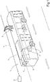
- FIG. 1 a simplified perspective view of a vehicle in the form of a bus 1 which according to the embodiment is of the electric type and is equipped with an electric machine 2 which can be used for operating the bus 1.
- a rear axle 3 which is connected to the electric machine 2.
- the bus 1 carries an electric energy storage system in the form of a battery pack 4 which in turn comprises a plurality of battery cells (not shown in detail in Fig. 1 ). As will be described in greater detail below, the battery cells are connected in series to provide an output DC voltage.
- the battery cells are of lithium iron phosphate (LiFePO4) type, but other types may also be used.
- the battery pack 4 is also connected to an electronic control unit 5 which is arranged for measuring one or more predetermined parameters which are indicative of the state of operation of the battery pack 4.
- the control unit 5 can be configured for measuring the voltage of the battery pack 4 and its battery cells, or one or more alternative parameters such as the battery current or the temperature of each battery cell. Such parameters can be used for controlling the condition and operation of the battery pack 4.
- the battery pack 4 will be described in greater detail below with reference to Fig. 2 .
- the battery pack 4 is arranged on the roof of the bus 1, as indicated in Fig. 1 , but other arrangements of the battery pack 4 are also possible within the scope of the invention.
- the energy storage system 4 will deliver the required power to the electric machine 2, which in turn is driving the rear axle 3.
- the manner in which an electric machine can be used for operating a vehicle is generally previously known and for this reason, it is not described in detail here.
- the bus 1 is equipped with a first electric connector element 6, suitably in the form of a pantograph which is mounted on the roof of the bus 1.
- the first connector element 6 is arranged for being connected to a second electric connector element 7 in the form of an overhead electrical conductor wire which is configured for conducting a charging current having a certain voltage.
- the overhead conductor 7 forms part of an external power supply 8, suitably in the form of an AC grid system.
- the battery pack 4 can be supplied with an electrical current by means of the connection between the overhead wire 7 and the pantograph 6. More precisely, the electric current is fed to an on-board charging unit 9 which is connected to the battery pack 4 for charging thereof.
- the charging unit 9 is also connected to the control unit 5.
- the pantograph 6 and the overhead wire 7 are arranged so that charging of the battery pack 4 takes place while the bus 1 is standing still, i.e. either at a charging station at a bus terminal or at a bus stop or a similar position.
- charging of the battery pack 4 can be carried out during operation of the bus 1.
- the vehicle 1 is arranged to be operated by means of the electric machine 2 only.
- the vehicle may be a hybrid vehicle, for example a so-called plug-in hybrid vehicle which is equipped with an internal combustion engine and an electric machine which are connected to each other via a clutch. Both the internal combustion engine and the electrical machine can then be used alternately or in parallel to operate the vehicle.
- the arrangement for charging can also be of the plug-in type comprising a charging cable connecting the battery in the vehicle to a charging station.
- a process for charging the battery pack 4 can be initiated when the bus approaches the overhead wire 7 so that the pantograph 6 and the wire 7 can come into contact with each other. This means that charging of the battery pack 4 is initiated upon connection of the battery pack 4 to the external power supply 8.
- the second connector element 7 it can be noted that it can be arranged as an overhead wire, as shown in Fig. 1 .
- the invention can be implemented with a second connector element in the form of a current conducting power rail which is arranged along the road surface. Such an arrangement is configured to cooperate with one or more current collectors which are movable and lowered towards the ground, and which may be configured to be connected with said current conducting power rail during operation of the vehicle.
- the invention can also be implemented by means of other types of conductors, for example current wires arranged along the side of a vehicle and corresponding with suitable current collectors on the vehicle.
- Fig. 2 is a schematic figure showing the battery pack 4, the control unit 5, the on-board charging unit 9 and certain other associated components of the vehicle 1.
- the battery pack 4 comprises a plurality of battery cells, symbolically represented by three battery cells 4a, 4b, 4c, which are connected in series and which provide an output battery voltage (V B ).
- the battery pack 4 contains a large number of battery cells, suitably in the magnitude of 200 cells, although the specific number may vary.
- the battery cells 4a, 4b, 4c are of the lithium iron phosphate (LiFePO 4 ) type, although the principles of the invention are equally applicable to other types of battery cells.
- the embodiment comprises one battery pack, it should be noted that the invention is applicable in cases where several battery packs are combined.
- the battery pack 4 is connected to an electric machine (not shown in Fig. 2 ) and is configured for operating said electric machine, which in turn operates the vehicle in question. Furthermore, the battery pack 4 is connected to the on-board charging unit 9 so as to allow charging of the battery pack 4 when the charging unit 9 is connected to the external power supply 8.
- the external power supply 8 is typically configured for supplying a 400 V AC three-phase voltage.
- the charging unit 9 is connected to the battery pack 4 via a positive main contactor 10 and a negative main contactor 11. The charging unit 9 typically supplies 600 V DC to the battery pack 4.
- a pre-charge contactor 12 is connected in parallel with the positive main contactor 10. Also, a pre-charge resistor 13 is connected in series with the pre-charge contactor 12. All the contactors 10, 11, 12 are connected to the control unit 5 and can be controlled by the control unit 5 in a manner which will be described in more detail below.
- control unit 5 is connected to the charging unit 9 and to the battery pack 4, and is arranged for initiating a balancing process for the battery pack 4 depending on the distribution of energy between the battery cells 4a, 4b, 4c. This will be described below.
- control unit 5 is configured for monitoring the status of the battery pack 7a, i.e. to monitor the status of each battery cell 4a, 4b, 4c.
- control unit 5 may be configured with sensor units (not shown) for measuring the voltage of each battery cell and for transmitting information related to measured voltage values to the control unit 5.
- the charging unit 9 is connected to a DC/DC converter 14, which is configured for supplying electric power to certain low voltage components, such as for example a second battery unit 15 for powering components such as air condition systems, heating devices and lighting units.
- a component to which the DC/DC converter 14 is connected is an electrical heater 16 which is configured for heating a liquid which flows in a liquid circuit 17.
- the liquid is pumped through the circuit 17 by means of a pump 18.
- the liquid circuit 17 is arranged close to the battery pack 4 so as to be used for a temperature control of said battery pack 4.
- the liquid circuit 17 also comprises a cooling package 19 such as a radiator or a heat exchanger. The liquid is transported in the liquid circuit 17 to the battery pack 4 and then back to the pump 18. In this manner, a temperature control of the battery pack 4 can be implemented.
- the on-board charging unit 9 supplies electric energy both in the form of a traction voltage which is supplied to the battery pack 4 and also a low voltage, via the DC/DC converter 14, to certain electric components of the vehicle such as the heater 16, the pump 18 and the low voltage battery 15.
- this invention relates to a method and system for balancing the battery pack 4. It is previously known that the battery cells of a battery pack may differ over time as regards their state of charge (SOC). This is due to the fact that as the battery cells are charged and discharged, the electric energy is distributed in an uneven manner between the cells. This means that, from time to time, there will be a need for a cell balancing process wherein the differences regarding the state of charge for the battery cells are evened out.
- SOC state of charge
- a known way of balancing battery cells is to generate energy by conducting current through a resistor which is coupled in parallel to each battery cell. This can be done for a number of battery cells for which the state of charge is relatively high. To be able to carry out this cell balancing, the cell voltage needs to be kept at a relatively high energy level in the cell. This is due to the inherent properties of the measured cell voltage and the corresponding state of charge parameters, which have a clear detectable relation to each other only when the cell voltage is relatively high.
- a sensor arrangement which is configured for measuring one or more parameters indicating the operation of the battery, for example in the form of a voltage sensor for each battery cell in order to measure the cell terminal voltage for each cell.
- a sensor arrangement could then be used for detecting various parameters related to the operation of the battery. This means that a cell balancing process can be initiated when the control unit 5 has detected that a given number of battery cells has a cell voltage and/or state of charge which differs from predetermined threshold values.
- a problem which may occur during the above-mentioned cell balancing process is that the cell voltage for the battery cells in question may drop considerably during said procedure. This means also that there may be a loss of charge from the battery pack 4 during the cell balancing, i.e. the energy from the battery cells may be drained to a certain extent. This means that the cell voltage may drop so much that it will be outside the part of the voltage versus state of charge curve in which there is a clear and defined relationship between the voltage and state of charge.
- the invention is based on the concept that it comprises a process of controlling a relatively small current i 1 , as indicated in Fig. 2 , which is supplied to the battery pack 4 during the balancing procedure.
- the current i 1 is supplied by means of the charging unit 9. This means that the loss of charge through the bleeder resistor of each battery cell in question can be limited. Also, the battery cell voltage drop will be limited during the cell balancing, which is an advantage.
- control unit 5 is adapted to control the charging unit 9 to feed a relatively low current i 1 to the battery pack 4 during the cell balancing.
- the supply of this relatively low current i 1 is suitably terminated when the cell balancing process is terminated.
- the current i 1 is controlled by feeding it through the resistor 13 during the cell balancing process. More precisely, since the magnitude of the resistance of the resistor 13 is known, the current i 1 can be calculated by measuring the voltage.
- the resistor 13 can be a so-called pre-charge resistor which forms part of the battery pack 4 and is configured for a pre-charge function in which an inrush current from the charging unit 9 can be limited when the battery pack 4 is connected to the charging unit 9. In this manner, the resistor 13 can be used to pre-charge a system capacitance, symbolically indicated by means of the letter C in Fig. 2 .
- the invention is not limited to arrangements comprising a pre-charge function but can be used also without such a function.
- the current i 1 is fed through a resistor which is not involved in any pre-charge function.
- the relatively small current i 1 is fed through the pre-charger resistor 13 for a certain time period, after which the pre-charge resistor 13 is disconnected by opening the pre-charge contactor 12. Next, the positive main contactor 10 is closed.
- the relatively small current i 1 is fed through the resistor 13 during a phase when the battery cells cannot receive any substantial amount of charge. Subsequently, when both the positive main contactor 10 and the negative main contactor 11 have been closed, the charging unit 9 can be used for normal charging of the battery pack 4.
- the relatively low current i 1 can be controlled since the battery pack voltage V B applied by the charging unit 9 is known. Also, the resistance of the resistor 13 is known. According to an embodiment, the resistance is of the magnitude 100 ohms. This means that the current through the resistor 13 can be accurately controlled during the cell balancing process by detecting the voltage drop over the resistor 13 and calculating the current. Alternatively, a current sensor (not shown) for detecting the battery current can be used in order to control the relatively low current i 1 .
- the relatively low current i 1 should preferably be approximately 100 mA. In any case, it should not exceed 200-300 mA.
- the actual magnitude of this current is chosen so as to compensate for the amount of discharge in the battery cells in question so that there is generally no voltage drop in the battery cells.
- the control of the current through the resistor 13 is used until the charge and discharge ability of the battery pack 4 have reached above a predetermined limit. At this stage, an accurate control of the current is no longer needed and the positive main contactor 10 can be closed.
- the magnitude can also be controlled to prevent damage to the battery cells in a relatively cold battery pack. By feeding a current through the resistor 13, the battery current is limited to a low level which cannot cause damage.
- the current i 1 can be kept at a relatively low level during the cell balancing process even if voltage variations in the electric system occur, for example in a situation where a load is connected or disconnected.
- Fig. 3 is a schematic flow chart illustrating the operation of the invention.
- the control unit 5 is configured for charging the battery pack 4 by having the positive main contactor 10 and the negative main contactor closed 11 (step 20 as shown in Fig. 3 ).
- the control unit 5 is also configured for detecting whether to initiate a cell balancing process (step 21). This is done by detecting whether there are battery cells having a voltage level or a state of charge (SOC) which deviates from certain predetermined threshold values. It is known that battery packs degrade over time, and by diagnosing certain battery parameters such as the cell terminal voltage, the cell capacity and the cell state of charge, an indication of the state of operation of the battery pack 4 can be obtained.
- SOC state of charge
- the charging unit 9 feeds the above-mentioned relatively low current i 1 to the battery pack (step 22).
- the current is controlled so as to compensate for a loss of charge which occurs in the battery pack 4 during the cell balancing process.
- the current i 1 is fed through the resistor 13, by closing the pre-charge contactor 12 and opening the positive main contactor 10.
- the current i 1 can be supplied to the battery pack by gradually increasing the current feed.
- the control unit 5 is arranged to continuously measure whether the cell balancing process is considered to be finished, which is when the voltage over the battery cells involved in the cell balancing have reached a predefined voltage range. At this stage, the balancing is considered to be completed (step 23). According to the embodiment, the feeding of the current i 1 is then also terminated. Next, the pre-charge resistor 13 is disconnected, i.e. the pre-charge contactor 12 is opened, and the positive main contactor 10 is again closed (step 24).
- vehicle 1 in the form of a bus
- the invention can generally be implemented in virtually any type of vehicle which is operated by means of at least an electric machine.
- vehicles include cars, buses, trams, transport vehicles, construction equipment and trains.
Landscapes
- Engineering & Computer Science (AREA)
- Power Engineering (AREA)
- Life Sciences & Earth Sciences (AREA)
- Sustainable Development (AREA)
- Sustainable Energy (AREA)
- Transportation (AREA)
- Mechanical Engineering (AREA)
- Secondary Cells (AREA)
- Charge And Discharge Circuits For Batteries Or The Like (AREA)
- Electric Propulsion And Braking For Vehicles (AREA)
Claims (12)
- Procédé d'équilibrage d'un bloc-batterie (4) comprenant une pluralité de cellules de batterie (4a, 4b, 4c) connectées en série et fournissant une tension de batterie de sortie (VB), ledit procédé comprenant les étapes suivantes :- initiation d'un processus (21) d'équilibrage dudit bloc-batterie (4) en fonction de la répartition d'énergie entre lesdites cellules de batterie (4a, 4b, 4c),- apport (22) d'un courant relativement faible (i1) n'excédant pas environ 300 mA à travers une résistance (13) qui est disposée en série avec ledit bloc-batterie (4), et apport dudit courant relativement faible (i1) audit bloc-batterie (4) pendant ledit équilibrage ;- mesure (23) de la tension à travers ladite résistance (13), en obtenant ainsi une valeur dudit courant (i1) ;- commande de l'amplitude dudit courant relativement faible de manière à ce qu'il soit apte à compenser une perte de charge électrique dans lesdites cellules de batterie pendant ledit équilibrage de cellules, une chute de tension de cellules de batterie desdites cellules de batteries étant limitée pendant l'équilibrage des cellules ; et- fin de l'étape d'apport dudit courant relativement faible (i1) lorsque ledit processus d'équilibrage est terminé.
- Procédé selon la revendication 1, comprenant en outre :- l'apport dudit courant (i1) pendant une phase où la capacité de charge et de décharge dudit bloc-batterie (4) est en dessous d'une limite prédéterminée.
- Procédé selon l'une quelconque des revendications 1 ou 2, comprenant en outre :- l'initiation dudit processus d'équilibrage du bloc-batterie (4) en transférant de l'énergie entre des cellules de batterie.
- Procédé selon l'une quelconque des revendications précédentes, comprenant en outre :- l'apport dudit courant (i1) à travers la résistance (13) pour limiter un courant d'appel lorsque ledit bloc-batterie (4) est connecté à une unité de chargement (9).
- Système de commande d'un courant étant apporté à un bloc-batterie (4) comprenant une pluralité de cellules de batterie (4a, 4b, 4c) connectées en série et fournissant une tension de batterie de sortie (VB), ledit système comprenant une unité de commande (5) qui est apte à apporter un courant relativement faible (i1) n'excédant pas environ 300 mA à travers une résistance (13) qui est disposée en série avec ledit bloc-batterie (4), et à mesurer la tension à travers ladite résistance (13), en obtenant ainsi une valeur dudit courant (i1), et l'unité de commande (5) étant en outre conçue pour initier un processus d'équilibrage dudit bloc-batterie (4) en fonction de la répartition d'énergie entre lesdites cellules de batterie (4a, 4b, 4c) pour apporter ledit courant relativement faible (i1) audit bloc-batterie (4) pendant ledit équilibrage, pour commander l'amplitude dudit courant relativement faible de manière à ce qu'il soit apte à compenser une perte de charge électrique dans lesdites cellules de batterie pendant ledit équilibrage de cellules, une chute de tension de cellules de batterie desdites cellules de batteries étant limitée pendant l'équilibrage des cellules, et à mettre fin à l'étape d'apport dudit courant relativement faible (i1) lorsque ledit processus d'équilibrage est terminé.
- Système selon la revendication 5, dans lequel l'unité de commande (5) est conçue pour apporter ledit courant (i1) pendant une période où la capacité de charge et de décharge dudit bloc-batterie (4) est en dessous d'une limite prédéterminée.
- Système selon la revendication 5 ou 6, dans lequel chaque cellule de batterie (4a, 4b, 4c) est associée à une résistance couplée en parallèle et est disposée de manière à être connectée sélectivement au moyen d'un interrupteur contrôlable pendant ledit processus d'équilibrage de batterie.
- Système selon l'une quelconque des revendications 5 à 7, dans lequel ladite unité de commande (5) est apte à commander l'amplitude dudit courant (i1) pour compenser une perte de charge électrique dans lesdites cellules de batterie (4a, 4b, 4c) pendant ledit équilibrage de cellules.
- Système selon l'une quelconque des revendications 5 à 8, comprenant en outre une unité de chargement (9) pour charger ledit bloc-batterie (4) pour apporter ledit courant relativement faible (i1) audit bloc-batterie (4) .
- Système selon la revendication 9, dans lequel ledit courant (i1) est apporté à travers ladite résistance (13) pour limiter un courant d'appel lorsque ledit bloc-batterie (4) est connecté à ladite unité de chargement (9) .
- Système selon la revendication 9 ou 10, dans lequel ledit bloc-batterie (4) comprend en outre un contacteur principal (10) et ladite unité de commande (5) est conçue pour fermer le contacteur principal (10) et déconnecter ladite résistance (13) après l'apport dudit courant (i1) .
- Véhicule (1) comprenant un système selon l'une quelconque des revendications 5 à 11.
Applications Claiming Priority (1)
| Application Number | Priority Date | Filing Date | Title |
|---|---|---|---|
| PCT/EP2016/052609 WO2017148496A1 (fr) | 2016-03-01 | 2016-03-01 | Procédé et système permettant de commander un courant qui est alimenté à un bloc-batterie |
Publications (2)
| Publication Number | Publication Date |
|---|---|
| EP3424123A1 EP3424123A1 (fr) | 2019-01-09 |
| EP3424123B1 true EP3424123B1 (fr) | 2022-08-03 |
Family
ID=55315429
Family Applications (1)
| Application Number | Title | Priority Date | Filing Date |
|---|---|---|---|
| EP16703536.9A Active EP3424123B1 (fr) | 2016-03-01 | 2016-03-01 | Procédé et système permettant de commander un courant qui est alimenté à un bloc-batterie |
Country Status (4)
| Country | Link |
|---|---|
| US (1) | US11437827B2 (fr) |
| EP (1) | EP3424123B1 (fr) |
| CN (1) | CN108702004B (fr) |
| WO (1) | WO2017148496A1 (fr) |
Families Citing this family (7)
| Publication number | Priority date | Publication date | Assignee | Title |
|---|---|---|---|---|
| WO2019147244A1 (fr) * | 2018-01-25 | 2019-08-01 | Volvo Construction Equipment Ab | Gestion de surcharge d'égaliseur |
| US20190322193A1 (en) * | 2018-04-19 | 2019-10-24 | Wayne State University | Battery module balancing system of a vehicle and method thereof |
| ES2970821T3 (es) | 2018-12-21 | 2024-05-30 | Salomon Amar | Uso de Akkermansia en el tratamiento de enfermedades orales |
| US11513164B2 (en) * | 2020-10-28 | 2022-11-29 | Guangzhou Automobile Group Co., Ltd. | Method and system for estimating battery pack balance state of new energy vehicle |
| CN114696381A (zh) * | 2020-12-29 | 2022-07-01 | 李尔公司 | 用于并行电池组充电的系统和方法 |
| FR3119822B1 (fr) * | 2021-02-18 | 2025-06-13 | SNCF Voyageurs | dispositif d’alimentation d’urgence d’un vehicule ferroviaire |
| CN115771430B (zh) * | 2022-11-28 | 2024-09-20 | 吉林大学 | 一种在线直流驱动运输系统的能耗优化方法 |
Citations (3)
| Publication number | Priority date | Publication date | Assignee | Title |
|---|---|---|---|---|
| US20110089897A1 (en) * | 2010-06-25 | 2011-04-21 | Wei Zhang | Battery pack with balancing management |
| US20120319658A1 (en) * | 2011-06-17 | 2012-12-20 | Southwest Electronic Energy Group | Module bypass switch with bypass current monitoring |
| KR20130071950A (ko) * | 2011-12-21 | 2013-07-01 | 주식회사 엘지화학 | 배터리 팩 전압 평형 방법 및 장치 |
Family Cites Families (79)
| Publication number | Priority date | Publication date | Assignee | Title |
|---|---|---|---|---|
| DK25391D0 (da) * | 1991-02-14 | 1991-02-14 | Pan Europ Holding S A | Fremgangsmaade og apparat til opladning af et genopladeligt batteri |
| JP3577751B2 (ja) * | 1993-12-24 | 2004-10-13 | ソニー株式会社 | バッテリー充電装置、バッテリーパック及びバッテリー充電方法 |
| CA2157814A1 (fr) * | 1994-09-09 | 1996-03-10 | David R. Pacholok | Egalisation de la charge des piles ou des batteries montees en serie |
| CA2169706A1 (fr) * | 1995-03-03 | 1996-09-04 | Troy Lynn Stockstad | Circuit de commande de charge d'une batterie d'accumulateurs, et methode connexe |
| US5952815A (en) * | 1997-07-25 | 1999-09-14 | Minnesota Mining & Manufacturing Co. | Equalizer system and method for series connected energy storing devices |
| US6037750A (en) * | 1998-09-17 | 2000-03-14 | Qualcomm Incorporated | Battery pack controller |
| US7615966B2 (en) * | 2001-05-25 | 2009-11-10 | Texas Instruments Northern Virginia Incorporated | Method and apparatus for managing energy in plural energy storage units |
| US7081737B2 (en) * | 2003-06-19 | 2006-07-25 | O2Micro International Limited | Battery cell monitoring and balancing circuit |
| US7599167B2 (en) * | 2004-02-17 | 2009-10-06 | Cooper Technologies Company | Active balancing circuit modules, systems and capacitor devices |
| US7772852B2 (en) * | 2004-07-21 | 2010-08-10 | C & C Power, Inc. | Battery string performance measurement |
| US7142019B2 (en) * | 2004-09-03 | 2006-11-28 | Texas Instruments Incorporated | System and method for reducing power-on transient current magnitude |
| US7719191B2 (en) | 2006-03-31 | 2010-05-18 | Panasonic Corporation | Plasma display panel |
| TWI317184B (en) * | 2006-07-17 | 2009-11-11 | Compal Electronics Inc | A hybrid battery module with a voltage balance unit and its charging and discharging method |
| JP4448111B2 (ja) * | 2006-07-31 | 2010-04-07 | 日立ビークルエナジー株式会社 | 電源システム |
| US8350529B2 (en) * | 2006-11-10 | 2013-01-08 | Lithium Balance A/S | Battery management system |
| US7782013B2 (en) * | 2007-04-17 | 2010-08-24 | Chun-Chieh Chang | Rechargeable battery assembly and method for recharging same |
| US8159191B2 (en) * | 2007-04-17 | 2012-04-17 | Tsun-Yu Chang | Advanced rechargeable battery system |
| US7777451B2 (en) * | 2007-04-17 | 2010-08-17 | Chun-Chieh Chang | Rechargeable battery assembly and power system using same |
| US7990108B2 (en) * | 2007-05-14 | 2011-08-02 | Atmel Corporation | Charge detector |
| JP5254568B2 (ja) * | 2007-05-16 | 2013-08-07 | 日立ビークルエナジー株式会社 | セルコントローラ、電池モジュールおよび電源システム |
| TW200913433A (en) * | 2007-09-10 | 2009-03-16 | J Tek Inc | Scattered energy storage control system |
| US8461806B2 (en) * | 2007-10-15 | 2013-06-11 | O2Micro Inc | Systems and methods for cell balancing |
| US20090079391A1 (en) * | 2007-09-25 | 2009-03-26 | O2Micro Inc. | Systems and methods for cell balancing |
| JP5127383B2 (ja) * | 2007-09-28 | 2013-01-23 | 株式会社日立製作所 | 電池用集積回路および該電池用集積回路を使用した車両用電源システム |
| JP5459946B2 (ja) * | 2007-09-28 | 2014-04-02 | 株式会社日立製作所 | 車両用直流電源装置 |
| JP5469813B2 (ja) * | 2008-01-29 | 2014-04-16 | 株式会社日立製作所 | 車両用電池システム |
| US7965061B2 (en) * | 2008-02-01 | 2011-06-21 | O2Micro, Inc. | Conversion systems with balanced cell currents |
| US8044640B2 (en) * | 2008-10-07 | 2011-10-25 | Black & Decker Inc. | Method for stepping current output by a battery charger |
| US8154248B2 (en) * | 2008-10-07 | 2012-04-10 | Black & Decker Inc. | Signal for pre-charge selection in lithium charging and discharge control/pre-charge function |
| JP5601770B2 (ja) * | 2008-12-09 | 2014-10-08 | 三菱重工業株式会社 | 電圧均等化装置、方法、プログラム、及び電力貯蔵システム |
| JP5133926B2 (ja) * | 2009-03-26 | 2013-01-30 | 株式会社日立製作所 | 車両用電池システム |
| JP2010246225A (ja) * | 2009-04-03 | 2010-10-28 | Sony Corp | 電池パックおよび充電方法 |
| US8957610B2 (en) * | 2009-07-02 | 2015-02-17 | Chong Uk Lee | Multi-port reconfigurable battery |
| JP2011130551A (ja) * | 2009-12-16 | 2011-06-30 | Sanyo Electric Co Ltd | 電源装置及びこれを備える車両 |
| KR101211756B1 (ko) * | 2010-02-11 | 2012-12-12 | 삼성에스디아이 주식회사 | 배터리 팩 |
| US8791669B2 (en) * | 2010-06-24 | 2014-07-29 | Qnovo Inc. | Method and circuitry to calculate the state of charge of a battery/cell |
| US8638070B2 (en) * | 2010-05-21 | 2014-01-28 | Qnovo Inc. | Method and circuitry to adaptively charge a battery/cell |
| US8723481B2 (en) * | 2010-06-25 | 2014-05-13 | O2Micro, Inc. | Battery pack with balancing management |
| US9037426B2 (en) * | 2011-05-13 | 2015-05-19 | GM Global Technology Operations LLC | Systems and methods for determining cell capacity values in a multi-cell battery |
| SE538214C2 (sv) * | 2011-06-17 | 2016-04-05 | Int Truck Intellectual Prop Co | Övervakande styrsystem för hybrid-elektriska drivlinor |
| US8643330B2 (en) * | 2011-09-02 | 2014-02-04 | Tesla Motors, Inc. | Method of operating a multiport vehicle charging system |
| AU2012323774A1 (en) * | 2011-10-14 | 2013-10-24 | Carbontrack Pty Ltd | Interface device for an energy harvesting system |
| DE102012000653A1 (de) * | 2012-01-14 | 2012-11-22 | Daimler Ag | Verfahren zur Steuerung des Potentialausgleichs von Batteriezellen und Batterievorrichtung |
| JP2013192394A (ja) * | 2012-03-14 | 2013-09-26 | Ricoh Co Ltd | 充電制御回路及び電池装置 |
| JP5971626B2 (ja) * | 2012-03-15 | 2016-08-17 | 株式会社日立製作所 | 電池システム |
| US9711962B2 (en) * | 2012-07-09 | 2017-07-18 | Davide Andrea | System and method for isolated DC to DC converter |
| US9217765B2 (en) * | 2012-08-09 | 2015-12-22 | GM Global Technology Operations LLC | Method and system for isolating voltage sensor and contactor faults in an electrical system |
| JP6081320B2 (ja) * | 2012-09-05 | 2017-02-15 | 株式会社東芝 | 電源装置、及び組電池の制御方法及び制御プログラム |
| US9300016B2 (en) * | 2012-09-14 | 2016-03-29 | Samsung Sdi Co., Ltd. | Battery system and energy storage system |
| JP5955714B2 (ja) * | 2012-09-18 | 2016-07-20 | 株式会社東芝 | 電池パックおよび電気自動車 |
| KR101962777B1 (ko) * | 2012-12-20 | 2019-07-31 | 온세미컨덕터코리아 주식회사 | 부하/충전기 감지 회로, 이를 포함하는 배터리 관리 시스템 및 그 구동 방법 |
| AU2014218321A1 (en) * | 2013-02-13 | 2015-09-24 | Carbontrack Pty Ltd | System and method for monitoring and control of appliances |
| US9472961B2 (en) * | 2013-02-25 | 2016-10-18 | Semiconductor Components Industries, Llc | Method of forming a balancing circuit for a plurality of battery cells and structure therefor |
| TWI627812B (zh) * | 2013-04-05 | 2018-06-21 | 美商線性科技股份有限公司 | 電壓補償主動電池平衡的裝置、系統及方法 |
| KR102028923B1 (ko) | 2013-04-11 | 2019-10-08 | 에스케이이노베이션 주식회사 | 배터리 밸런싱 장치 및 방법 |
| FR3005535B1 (fr) * | 2013-05-09 | 2016-10-21 | Commissariat Energie Atomique | Systeme de securisation pour module de batterie d'accumulateurs et procede d'equilibrage d'un module de batterie correspondant |
| US20140340023A1 (en) * | 2013-05-17 | 2014-11-20 | Ying-Haw Shu | Hybrid battery balancing system |
| US9925933B2 (en) * | 2013-08-30 | 2018-03-27 | Ford Global Technologies, Llc | Pre-charge quick key cycling protection |
| US9925878B2 (en) * | 2013-09-26 | 2018-03-27 | Ford Global Technologies, Llc | Bus pre-charge control using a buck converter |
| KR20150085383A (ko) * | 2014-01-15 | 2015-07-23 | 삼성에스디아이 주식회사 | 배터리 시스템 및 배터리 시스템을 포함하는 에너지 저장 시스템 |
| KR101726921B1 (ko) * | 2014-02-20 | 2017-04-13 | 주식회사 엘지화학 | 전류 측정을 통한 배터리 랙 파손 방지 장치, 시스템 및 방법 |
| JP6187326B2 (ja) * | 2014-03-06 | 2017-08-30 | 株式会社デンソー | 電池パック |
| JP6404640B2 (ja) * | 2014-08-22 | 2018-10-10 | 株式会社マキタ | 電動機械器具用バッテリパック |
| KR101783919B1 (ko) * | 2014-10-31 | 2017-10-10 | 주식회사 엘지화학 | 개방전압 추정 장치 및 방법 |
| CN104505550B (zh) * | 2014-12-25 | 2017-01-18 | 宁德时代新能源科技股份有限公司 | 磷酸铁锂电池组的被动均衡方法及系统 |
| KR20160099357A (ko) * | 2015-02-12 | 2016-08-22 | 삼성에스디아이 주식회사 | 배터리 팩 및 이를 포함하는 배터리 시스템 |
| US9608458B2 (en) * | 2015-03-18 | 2017-03-28 | NEC Energy Solutons, Inc. | Buck pre-charger for series-connected battery modules |
| KR20160134120A (ko) * | 2015-05-14 | 2016-11-23 | 삼성에스디아이 주식회사 | 자동차 배터리 시스템 |
| KR101698908B1 (ko) * | 2015-05-14 | 2017-02-01 | 주식회사 대화알로이테크 | 하이브리드 차량용 배터리 프리 히팅장치 및 그 제어 방법 |
| KR102436418B1 (ko) * | 2015-07-02 | 2022-08-25 | 삼성에스디아이 주식회사 | 배터리 팩의 전류 측정 방법 |
| GB201523105D0 (en) * | 2015-12-30 | 2016-02-10 | Hyperdrive Innovation Ltd | Battery management system |
| WO2017154146A1 (fr) * | 2016-03-09 | 2017-09-14 | 株式会社東芝 | Dispositif batterie de stockage, procédé de commande de dispositif batterie de stockage, et programme |
| CN108701871B (zh) * | 2016-03-15 | 2021-08-31 | 株式会社东芝 | 蓄电池装置、蓄电池装置的控制方法及程序 |
| GB2559533B (en) * | 2017-03-10 | 2019-02-13 | O2Micro Inc | Systems and methods for controlling battery current |
| US10720672B2 (en) * | 2017-04-24 | 2020-07-21 | Autel Robotics Co., Ltd | Series-multiple battery pack management system |
| US10444295B2 (en) * | 2017-12-20 | 2019-10-15 | National Chung Shan Institute Of Science And Technology | Battery balance management circuit |
| US10693300B2 (en) * | 2017-12-28 | 2020-06-23 | Saft America | Stepwise battery module precharge and post-discharge of high voltage battery systems |
| US10355496B1 (en) * | 2018-07-26 | 2019-07-16 | Kitty Hawk Corporation | Inter-module battery balancing using minimum cell voltages to select battery sub-modules to power loads |
| CN109037814B (zh) * | 2018-09-05 | 2021-02-19 | 成都芯源系统有限公司 | 一种充电平衡管理电路和方法 |
-
2016
- 2016-03-01 WO PCT/EP2016/052609 patent/WO2017148496A1/fr not_active Ceased
- 2016-03-01 EP EP16703536.9A patent/EP3424123B1/fr active Active
- 2016-03-01 CN CN201680082967.6A patent/CN108702004B/zh not_active Expired - Fee Related
- 2016-03-01 US US16/080,558 patent/US11437827B2/en active Active
Patent Citations (3)
| Publication number | Priority date | Publication date | Assignee | Title |
|---|---|---|---|---|
| US20110089897A1 (en) * | 2010-06-25 | 2011-04-21 | Wei Zhang | Battery pack with balancing management |
| US20120319658A1 (en) * | 2011-06-17 | 2012-12-20 | Southwest Electronic Energy Group | Module bypass switch with bypass current monitoring |
| KR20130071950A (ko) * | 2011-12-21 | 2013-07-01 | 주식회사 엘지화학 | 배터리 팩 전압 평형 방법 및 장치 |
Also Published As
| Publication number | Publication date |
|---|---|
| WO2017148496A1 (fr) | 2017-09-08 |
| US20190089167A1 (en) | 2019-03-21 |
| EP3424123A1 (fr) | 2019-01-09 |
| CN108702004A (zh) | 2018-10-23 |
| US11437827B2 (en) | 2022-09-06 |
| CN108702004B (zh) | 2022-05-03 |
Similar Documents
| Publication | Publication Date | Title |
|---|---|---|
| EP3424123B1 (fr) | Procédé et système permettant de commander un courant qui est alimenté à un bloc-batterie | |
| US10259336B2 (en) | Charging a battery using interpack switch | |
| US10809305B2 (en) | System and method for detecting and responding to a battery over-discharge condition within a vehicle | |
| US8378623B2 (en) | Apparatus and method for charging an electric vehicle | |
| EP3110652B1 (fr) | Système de stockage électrique pour véhicule et procédé de contrôle | |
| EP3463965B1 (fr) | Procédé et système pour le conditionnement thermique d'une batterie | |
| CN107009905A (zh) | 基于电气化车辆电池中的锂镀覆检测的车辆控制 | |
| US11214171B2 (en) | Mixed battery pack control | |
| EP3232049B1 (fr) | Système de commande de démarrage de véhicule automobile et véhicule automobile | |
| US20170166078A1 (en) | Battery charge equalization system | |
| US12246617B2 (en) | Vehicle traction battery circuit and control system | |
| US11146078B2 (en) | Method and arrangement for balancing a battery pack | |
| US11603011B2 (en) | Lithium plating detection and mitigation in electric vehicle batteries | |
| US20210155116A1 (en) | Balancing cells of a traction battery using statistical analysis | |
| WO2015185070A1 (fr) | Procédé et système permettant de surveiller l'état d'éléments de batterie | |
| GB2598375A (en) | Vehicle traction battery control system | |
| US20240409130A1 (en) | Rail vehicle traction system and associated rail vehicle |
Legal Events
| Date | Code | Title | Description |
|---|---|---|---|
| STAA | Information on the status of an ep patent application or granted ep patent |
Free format text: STATUS: THE INTERNATIONAL PUBLICATION HAS BEEN MADE |
|
| PUAI | Public reference made under article 153(3) epc to a published international application that has entered the european phase |
Free format text: ORIGINAL CODE: 0009012 |
|
| STAA | Information on the status of an ep patent application or granted ep patent |
Free format text: STATUS: REQUEST FOR EXAMINATION WAS MADE |
|
| 17P | Request for examination filed |
Effective date: 20180928 |
|
| AK | Designated contracting states |
Kind code of ref document: A1 Designated state(s): AL AT BE BG CH CY CZ DE DK EE ES FI FR GB GR HR HU IE IS IT LI LT LU LV MC MK MT NL NO PL PT RO RS SE SI SK SM TR |
|
| AX | Request for extension of the european patent |
Extension state: BA ME |
|
| DAV | Request for validation of the european patent (deleted) | ||
| DAX | Request for extension of the european patent (deleted) | ||
| STAA | Information on the status of an ep patent application or granted ep patent |
Free format text: STATUS: EXAMINATION IS IN PROGRESS |
|
| 17Q | First examination report despatched |
Effective date: 20191001 |
|
| GRAP | Despatch of communication of intention to grant a patent |
Free format text: ORIGINAL CODE: EPIDOSNIGR1 |
|
| STAA | Information on the status of an ep patent application or granted ep patent |
Free format text: STATUS: GRANT OF PATENT IS INTENDED |
|
| INTG | Intention to grant announced |
Effective date: 20211025 |
|
| GRAJ | Information related to disapproval of communication of intention to grant by the applicant or resumption of examination proceedings by the epo deleted |
Free format text: ORIGINAL CODE: EPIDOSDIGR1 |
|
| STAA | Information on the status of an ep patent application or granted ep patent |
Free format text: STATUS: EXAMINATION IS IN PROGRESS |
|
| GRAP | Despatch of communication of intention to grant a patent |
Free format text: ORIGINAL CODE: EPIDOSNIGR1 |
|
| STAA | Information on the status of an ep patent application or granted ep patent |
Free format text: STATUS: GRANT OF PATENT IS INTENDED |
|
| INTC | Intention to grant announced (deleted) | ||
| INTG | Intention to grant announced |
Effective date: 20220318 |
|
| GRAS | Grant fee paid |
Free format text: ORIGINAL CODE: EPIDOSNIGR3 |
|
| GRAA | (expected) grant |
Free format text: ORIGINAL CODE: 0009210 |
|
| STAA | Information on the status of an ep patent application or granted ep patent |
Free format text: STATUS: THE PATENT HAS BEEN GRANTED |
|
| AK | Designated contracting states |
Kind code of ref document: B1 Designated state(s): AL AT BE BG CH CY CZ DE DK EE ES FI FR GB GR HR HU IE IS IT LI LT LU LV MC MK MT NL NO PL PT RO RS SE SI SK SM TR |
|
| REG | Reference to a national code |
Ref country code: AT Ref legal event code: REF Ref document number: 1509535 Country of ref document: AT Kind code of ref document: T Effective date: 20220815 Ref country code: CH Ref legal event code: EP |
|
| REG | Reference to a national code |
Ref country code: DE Ref legal event code: R096 Ref document number: 602016073925 Country of ref document: DE |
|
| REG | Reference to a national code |
Ref country code: IE Ref legal event code: FG4D |
|
| REG | Reference to a national code |
Ref country code: NL Ref legal event code: FP |
|
| REG | Reference to a national code |
Ref country code: LT Ref legal event code: MG9D |
|
| PG25 | Lapsed in a contracting state [announced via postgrant information from national office to epo] |
Ref country code: SE Free format text: LAPSE BECAUSE OF FAILURE TO SUBMIT A TRANSLATION OF THE DESCRIPTION OR TO PAY THE FEE WITHIN THE PRESCRIBED TIME-LIMIT Effective date: 20220803 Ref country code: RS Free format text: LAPSE BECAUSE OF FAILURE TO SUBMIT A TRANSLATION OF THE DESCRIPTION OR TO PAY THE FEE WITHIN THE PRESCRIBED TIME-LIMIT Effective date: 20220803 Ref country code: PT Free format text: LAPSE BECAUSE OF FAILURE TO SUBMIT A TRANSLATION OF THE DESCRIPTION OR TO PAY THE FEE WITHIN THE PRESCRIBED TIME-LIMIT Effective date: 20221205 Ref country code: NO Free format text: LAPSE BECAUSE OF FAILURE TO SUBMIT A TRANSLATION OF THE DESCRIPTION OR TO PAY THE FEE WITHIN THE PRESCRIBED TIME-LIMIT Effective date: 20221103 Ref country code: LV Free format text: LAPSE BECAUSE OF FAILURE TO SUBMIT A TRANSLATION OF THE DESCRIPTION OR TO PAY THE FEE WITHIN THE PRESCRIBED TIME-LIMIT Effective date: 20220803 Ref country code: LT Free format text: LAPSE BECAUSE OF FAILURE TO SUBMIT A TRANSLATION OF THE DESCRIPTION OR TO PAY THE FEE WITHIN THE PRESCRIBED TIME-LIMIT Effective date: 20220803 Ref country code: FI Free format text: LAPSE BECAUSE OF FAILURE TO SUBMIT A TRANSLATION OF THE DESCRIPTION OR TO PAY THE FEE WITHIN THE PRESCRIBED TIME-LIMIT Effective date: 20220803 Ref country code: ES Free format text: LAPSE BECAUSE OF FAILURE TO SUBMIT A TRANSLATION OF THE DESCRIPTION OR TO PAY THE FEE WITHIN THE PRESCRIBED TIME-LIMIT Effective date: 20220803 |
|
| REG | Reference to a national code |
Ref country code: AT Ref legal event code: MK05 Ref document number: 1509535 Country of ref document: AT Kind code of ref document: T Effective date: 20220803 |
|
| PG25 | Lapsed in a contracting state [announced via postgrant information from national office to epo] |
Ref country code: PL Free format text: LAPSE BECAUSE OF FAILURE TO SUBMIT A TRANSLATION OF THE DESCRIPTION OR TO PAY THE FEE WITHIN THE PRESCRIBED TIME-LIMIT Effective date: 20220803 Ref country code: IS Free format text: LAPSE BECAUSE OF FAILURE TO SUBMIT A TRANSLATION OF THE DESCRIPTION OR TO PAY THE FEE WITHIN THE PRESCRIBED TIME-LIMIT Effective date: 20221203 Ref country code: HR Free format text: LAPSE BECAUSE OF FAILURE TO SUBMIT A TRANSLATION OF THE DESCRIPTION OR TO PAY THE FEE WITHIN THE PRESCRIBED TIME-LIMIT Effective date: 20220803 Ref country code: GR Free format text: LAPSE BECAUSE OF FAILURE TO SUBMIT A TRANSLATION OF THE DESCRIPTION OR TO PAY THE FEE WITHIN THE PRESCRIBED TIME-LIMIT Effective date: 20221104 |
|
| PG25 | Lapsed in a contracting state [announced via postgrant information from national office to epo] |
Ref country code: SM Free format text: LAPSE BECAUSE OF FAILURE TO SUBMIT A TRANSLATION OF THE DESCRIPTION OR TO PAY THE FEE WITHIN THE PRESCRIBED TIME-LIMIT Effective date: 20220803 Ref country code: RO Free format text: LAPSE BECAUSE OF FAILURE TO SUBMIT A TRANSLATION OF THE DESCRIPTION OR TO PAY THE FEE WITHIN THE PRESCRIBED TIME-LIMIT Effective date: 20220803 Ref country code: DK Free format text: LAPSE BECAUSE OF FAILURE TO SUBMIT A TRANSLATION OF THE DESCRIPTION OR TO PAY THE FEE WITHIN THE PRESCRIBED TIME-LIMIT Effective date: 20220803 Ref country code: CZ Free format text: LAPSE BECAUSE OF FAILURE TO SUBMIT A TRANSLATION OF THE DESCRIPTION OR TO PAY THE FEE WITHIN THE PRESCRIBED TIME-LIMIT Effective date: 20220803 Ref country code: AT Free format text: LAPSE BECAUSE OF FAILURE TO SUBMIT A TRANSLATION OF THE DESCRIPTION OR TO PAY THE FEE WITHIN THE PRESCRIBED TIME-LIMIT Effective date: 20220803 |
|
| REG | Reference to a national code |
Ref country code: DE Ref legal event code: R097 Ref document number: 602016073925 Country of ref document: DE |
|
| PG25 | Lapsed in a contracting state [announced via postgrant information from national office to epo] |
Ref country code: SK Free format text: LAPSE BECAUSE OF FAILURE TO SUBMIT A TRANSLATION OF THE DESCRIPTION OR TO PAY THE FEE WITHIN THE PRESCRIBED TIME-LIMIT Effective date: 20220803 Ref country code: EE Free format text: LAPSE BECAUSE OF FAILURE TO SUBMIT A TRANSLATION OF THE DESCRIPTION OR TO PAY THE FEE WITHIN THE PRESCRIBED TIME-LIMIT Effective date: 20220803 |
|
| PLBE | No opposition filed within time limit |
Free format text: ORIGINAL CODE: 0009261 |
|
| STAA | Information on the status of an ep patent application or granted ep patent |
Free format text: STATUS: NO OPPOSITION FILED WITHIN TIME LIMIT |
|
| PG25 | Lapsed in a contracting state [announced via postgrant information from national office to epo] |
Ref country code: AL Free format text: LAPSE BECAUSE OF FAILURE TO SUBMIT A TRANSLATION OF THE DESCRIPTION OR TO PAY THE FEE WITHIN THE PRESCRIBED TIME-LIMIT Effective date: 20220803 |
|
| 26N | No opposition filed |
Effective date: 20230504 |
|
| PG25 | Lapsed in a contracting state [announced via postgrant information from national office to epo] |
Ref country code: SI Free format text: LAPSE BECAUSE OF FAILURE TO SUBMIT A TRANSLATION OF THE DESCRIPTION OR TO PAY THE FEE WITHIN THE PRESCRIBED TIME-LIMIT Effective date: 20220803 |
|
| PG25 | Lapsed in a contracting state [announced via postgrant information from national office to epo] |
Ref country code: MC Free format text: LAPSE BECAUSE OF FAILURE TO SUBMIT A TRANSLATION OF THE DESCRIPTION OR TO PAY THE FEE WITHIN THE PRESCRIBED TIME-LIMIT Effective date: 20220803 |
|
| REG | Reference to a national code |
Ref country code: CH Ref legal event code: PL |
|
| GBPC | Gb: european patent ceased through non-payment of renewal fee |
Effective date: 20230301 |
|
| REG | Reference to a national code |
Ref country code: BE Ref legal event code: MM Effective date: 20230331 |
|
| PG25 | Lapsed in a contracting state [announced via postgrant information from national office to epo] |
Ref country code: LU Free format text: LAPSE BECAUSE OF NON-PAYMENT OF DUE FEES Effective date: 20230301 |
|
| REG | Reference to a national code |
Ref country code: IE Ref legal event code: MM4A |
|
| PG25 | Lapsed in a contracting state [announced via postgrant information from national office to epo] |
Ref country code: GB Free format text: LAPSE BECAUSE OF NON-PAYMENT OF DUE FEES Effective date: 20230301 |
|
| PG25 | Lapsed in a contracting state [announced via postgrant information from national office to epo] |
Ref country code: LI Free format text: LAPSE BECAUSE OF NON-PAYMENT OF DUE FEES Effective date: 20230331 Ref country code: IE Free format text: LAPSE BECAUSE OF NON-PAYMENT OF DUE FEES Effective date: 20230301 Ref country code: GB Free format text: LAPSE BECAUSE OF NON-PAYMENT OF DUE FEES Effective date: 20230301 Ref country code: CH Free format text: LAPSE BECAUSE OF NON-PAYMENT OF DUE FEES Effective date: 20230331 |
|
| PG25 | Lapsed in a contracting state [announced via postgrant information from national office to epo] |
Ref country code: BE Free format text: LAPSE BECAUSE OF NON-PAYMENT OF DUE FEES Effective date: 20230331 |
|
| PGFP | Annual fee paid to national office [announced via postgrant information from national office to epo] |
Ref country code: NL Payment date: 20240326 Year of fee payment: 9 |
|
| PG25 | Lapsed in a contracting state [announced via postgrant information from national office to epo] |
Ref country code: IT Free format text: LAPSE BECAUSE OF FAILURE TO SUBMIT A TRANSLATION OF THE DESCRIPTION OR TO PAY THE FEE WITHIN THE PRESCRIBED TIME-LIMIT Effective date: 20220803 |
|
| PGFP | Annual fee paid to national office [announced via postgrant information from national office to epo] |
Ref country code: FR Payment date: 20240327 Year of fee payment: 9 |
|
| PG25 | Lapsed in a contracting state [announced via postgrant information from national office to epo] |
Ref country code: BG Free format text: LAPSE BECAUSE OF FAILURE TO SUBMIT A TRANSLATION OF THE DESCRIPTION OR TO PAY THE FEE WITHIN THE PRESCRIBED TIME-LIMIT Effective date: 20220803 |
|
| PG25 | Lapsed in a contracting state [announced via postgrant information from national office to epo] |
Ref country code: BG Free format text: LAPSE BECAUSE OF FAILURE TO SUBMIT A TRANSLATION OF THE DESCRIPTION OR TO PAY THE FEE WITHIN THE PRESCRIBED TIME-LIMIT Effective date: 20220803 |
|
| PG25 | Lapsed in a contracting state [announced via postgrant information from national office to epo] |
Ref country code: CY Free format text: LAPSE BECAUSE OF FAILURE TO SUBMIT A TRANSLATION OF THE DESCRIPTION OR TO PAY THE FEE WITHIN THE PRESCRIBED TIME-LIMIT; INVALID AB INITIO Effective date: 20160301 |
|
| PG25 | Lapsed in a contracting state [announced via postgrant information from national office to epo] |
Ref country code: HU Free format text: LAPSE BECAUSE OF FAILURE TO SUBMIT A TRANSLATION OF THE DESCRIPTION OR TO PAY THE FEE WITHIN THE PRESCRIBED TIME-LIMIT; INVALID AB INITIO Effective date: 20160301 |
|
| REG | Reference to a national code |
Ref country code: NL Ref legal event code: MM Effective date: 20250401 |
|
| PG25 | Lapsed in a contracting state [announced via postgrant information from national office to epo] |
Ref country code: TR Free format text: LAPSE BECAUSE OF FAILURE TO SUBMIT A TRANSLATION OF THE DESCRIPTION OR TO PAY THE FEE WITHIN THE PRESCRIBED TIME-LIMIT Effective date: 20220803 |
|
| PG25 | Lapsed in a contracting state [announced via postgrant information from national office to epo] |
Ref country code: NL Free format text: LAPSE BECAUSE OF NON-PAYMENT OF DUE FEES Effective date: 20250401 |
|
| PG25 | Lapsed in a contracting state [announced via postgrant information from national office to epo] |
Ref country code: FR Free format text: LAPSE BECAUSE OF NON-PAYMENT OF DUE FEES Effective date: 20250331 |
|
| PGFP | Annual fee paid to national office [announced via postgrant information from national office to epo] |
Ref country code: DE Payment date: 20260320 Year of fee payment: 11 |