EP3424607B1 - Formvorrichtung und formverfahren - Google Patents
Formvorrichtung und formverfahren Download PDFInfo
- Publication number
- EP3424607B1 EP3424607B1 EP17759581.6A EP17759581A EP3424607B1 EP 3424607 B1 EP3424607 B1 EP 3424607B1 EP 17759581 A EP17759581 A EP 17759581A EP 3424607 B1 EP3424607 B1 EP 3424607B1
- Authority
- EP
- European Patent Office
- Prior art keywords
- metal pipe
- gas
- die
- pressure
- pipe material
- Prior art date
- Legal status (The legal status is an assumption and is not a legal conclusion. Google has not performed a legal analysis and makes no representation as to the accuracy of the status listed.)
- Active
Links
Images





Classifications
-
- B—PERFORMING OPERATIONS; TRANSPORTING
- B21—MECHANICAL METAL-WORKING WITHOUT ESSENTIALLY REMOVING MATERIAL; PUNCHING METAL
- B21D—WORKING OR PROCESSING OF SHEET METAL OR METAL TUBES, RODS OR PROFILES WITHOUT ESSENTIALLY REMOVING MATERIAL; PUNCHING METAL
- B21D26/00—Shaping without cutting otherwise than using rigid devices or tools or yieldable or resilient pads, i.e. applying fluid pressure or magnetic forces
- B21D26/02—Shaping without cutting otherwise than using rigid devices or tools or yieldable or resilient pads, i.e. applying fluid pressure or magnetic forces by applying fluid pressure
- B21D26/033—Deforming tubular bodies
- B21D26/041—Means for controlling fluid parameters, e.g. pressure or temperature
-
- B—PERFORMING OPERATIONS; TRANSPORTING
- B21—MECHANICAL METAL-WORKING WITHOUT ESSENTIALLY REMOVING MATERIAL; PUNCHING METAL
- B21D—WORKING OR PROCESSING OF SHEET METAL OR METAL TUBES, RODS OR PROFILES WITHOUT ESSENTIALLY REMOVING MATERIAL; PUNCHING METAL
- B21D19/00—Flanging or other edge treatment, e.g. of tubes
- B21D19/08—Flanging or other edge treatment, e.g. of tubes by single or successive action of pressing tools, e.g. vice jaws
-
- B—PERFORMING OPERATIONS; TRANSPORTING
- B21—MECHANICAL METAL-WORKING WITHOUT ESSENTIALLY REMOVING MATERIAL; PUNCHING METAL
- B21D—WORKING OR PROCESSING OF SHEET METAL OR METAL TUBES, RODS OR PROFILES WITHOUT ESSENTIALLY REMOVING MATERIAL; PUNCHING METAL
- B21D22/00—Shaping without cutting, by stamping, spinning, or deep-drawing
- B21D22/02—Stamping using rigid devices or tools
- B21D22/025—Stamping using rigid devices or tools for tubular articles
-
- B—PERFORMING OPERATIONS; TRANSPORTING
- B21—MECHANICAL METAL-WORKING WITHOUT ESSENTIALLY REMOVING MATERIAL; PUNCHING METAL
- B21D—WORKING OR PROCESSING OF SHEET METAL OR METAL TUBES, RODS OR PROFILES WITHOUT ESSENTIALLY REMOVING MATERIAL; PUNCHING METAL
- B21D26/00—Shaping without cutting otherwise than using rigid devices or tools or yieldable or resilient pads, i.e. applying fluid pressure or magnetic forces
- B21D26/02—Shaping without cutting otherwise than using rigid devices or tools or yieldable or resilient pads, i.e. applying fluid pressure or magnetic forces by applying fluid pressure
- B21D26/033—Deforming tubular bodies
- B21D26/037—Forming branched tubes
-
- B—PERFORMING OPERATIONS; TRANSPORTING
- B21—MECHANICAL METAL-WORKING WITHOUT ESSENTIALLY REMOVING MATERIAL; PUNCHING METAL
- B21D—WORKING OR PROCESSING OF SHEET METAL OR METAL TUBES, RODS OR PROFILES WITHOUT ESSENTIALLY REMOVING MATERIAL; PUNCHING METAL
- B21D26/00—Shaping without cutting otherwise than using rigid devices or tools or yieldable or resilient pads, i.e. applying fluid pressure or magnetic forces
- B21D26/02—Shaping without cutting otherwise than using rigid devices or tools or yieldable or resilient pads, i.e. applying fluid pressure or magnetic forces by applying fluid pressure
- B21D26/033—Deforming tubular bodies
- B21D26/043—Means for controlling the axial pusher
-
- B—PERFORMING OPERATIONS; TRANSPORTING
- B21—MECHANICAL METAL-WORKING WITHOUT ESSENTIALLY REMOVING MATERIAL; PUNCHING METAL
- B21D—WORKING OR PROCESSING OF SHEET METAL OR METAL TUBES, RODS OR PROFILES WITHOUT ESSENTIALLY REMOVING MATERIAL; PUNCHING METAL
- B21D26/00—Shaping without cutting otherwise than using rigid devices or tools or yieldable or resilient pads, i.e. applying fluid pressure or magnetic forces
- B21D26/02—Shaping without cutting otherwise than using rigid devices or tools or yieldable or resilient pads, i.e. applying fluid pressure or magnetic forces by applying fluid pressure
- B21D26/033—Deforming tubular bodies
- B21D26/047—Mould construction
-
- B—PERFORMING OPERATIONS; TRANSPORTING
- B21—MECHANICAL METAL-WORKING WITHOUT ESSENTIALLY REMOVING MATERIAL; PUNCHING METAL
- B21D—WORKING OR PROCESSING OF SHEET METAL OR METAL TUBES, RODS OR PROFILES WITHOUT ESSENTIALLY REMOVING MATERIAL; PUNCHING METAL
- B21D37/00—Tools as parts of machines covered by this subclass
- B21D37/16—Heating or cooling
-
- B—PERFORMING OPERATIONS; TRANSPORTING
- B21—MECHANICAL METAL-WORKING WITHOUT ESSENTIALLY REMOVING MATERIAL; PUNCHING METAL
- B21D—WORKING OR PROCESSING OF SHEET METAL OR METAL TUBES, RODS OR PROFILES WITHOUT ESSENTIALLY REMOVING MATERIAL; PUNCHING METAL
- B21D26/00—Shaping without cutting otherwise than using rigid devices or tools or yieldable or resilient pads, i.e. applying fluid pressure or magnetic forces
- B21D26/02—Shaping without cutting otherwise than using rigid devices or tools or yieldable or resilient pads, i.e. applying fluid pressure or magnetic forces by applying fluid pressure
- B21D26/033—Deforming tubular bodies
- B21D26/039—Means for controlling the clamping or opening of the moulds
-
- B—PERFORMING OPERATIONS; TRANSPORTING
- B21—MECHANICAL METAL-WORKING WITHOUT ESSENTIALLY REMOVING MATERIAL; PUNCHING METAL
- B21D—WORKING OR PROCESSING OF SHEET METAL OR METAL TUBES, RODS OR PROFILES WITHOUT ESSENTIALLY REMOVING MATERIAL; PUNCHING METAL
- B21D26/00—Shaping without cutting otherwise than using rigid devices or tools or yieldable or resilient pads, i.e. applying fluid pressure or magnetic forces
- B21D26/02—Shaping without cutting otherwise than using rigid devices or tools or yieldable or resilient pads, i.e. applying fluid pressure or magnetic forces by applying fluid pressure
- B21D26/033—Deforming tubular bodies
- B21D26/045—Closing or sealing means
Definitions
- the present invention relates to a forming device and a forming method.
- a forming device in which a gas is supplied into a heated metal pipe material so as to expand the metal pipe material and a metal pipe having a pipe portion and a flange portion is formed.
- a forming device described in PTL 1 includes an upper die and a lower die which are paired with each other, a gas supply unit which supplies a gas into a metal pipe material held between the upper die and the lower die, a first cavity portion (main cavity) which is formed by joining between the upper die and the lower die and forms a pipe portion, and a second cavity portion (sub cavity) which communicates with the first cavity portion and forms a flange portion.
- the dies are closed and the gas is supplied into the heated metal pipe material so as to expand the metal pipe material, and thus, the pipe portion and the flange portion can be simultaneously formed.
- the expanded metal pipe material comes into contact with portions of the upper die and the lower die constituting the first cavity portion, and thus, hardening of the metal pipe is performed.
- this hardening is performed, adhesion between the metal pipe, and the upper die and the lower die may decrease, and thus, there is a problem that variations in hardenability of the metal pipe occur.
- An object of the present invention is to provide a forming device and a forming method capable of suppressing variations in the hardenability of the metal pipe.
- the controller controls the gas supply of the gas supply unit so as to maintain the pressure in the metal pipe material at the first pressure. Accordingly, it is possible to prevent pressure drop in the pipe portion caused by cooling of the pipe portion due to a contact between the first die and the second die forming the first cavity portion and the pipe portion. The pressure drop in the pipe portion is prevented, and thus, it is possible to suppress a decrease in a force for pressing the pipe portion against the first and second dies. Accordingly, it is possible to suppress a decrease in adhesion between the pipe portion, and the first die and the second die when the metal pipe is formed, and it is possible to suppress occurrence of variations in hardenability in the pipe portion of the metal pipe.
- the first die and the second die may constitute a second cavity portion which communicates with the first cavity portion so as to form a flange portion of the metal pipe, in addition to the first cavity portion, and the controller may control the gas supply of the gas supply unit so as to expand a portion of the metal pipe material in the second cavity portion when the flange portion is formed from the metal pipe material before the pipe portion is formed.
- the controller may control the gas supply of the gas supply unit so as to expand a portion of the metal pipe material in the second cavity portion when the flange portion is formed from the metal pipe material before the pipe portion is formed.
- a portion of the metal pipe material in the second cavity portion is expanded before the pipe portion is formed, the expanded portion of the metal pipe material is pressed by the first die and the second die, and it is possible to form the flange portion. Accordingly, it is possible to easily form the flange portion and the pipe portion having a desired shape.
- the controller may control the gas supply of the gas supply unit so as to maintain the pressure of the gas in the metal pipe material at a second pressure lower than the first pressure.
- the controller may control the gas supply of the gas supply unit so as to maintain the pressure of the gas in the metal pipe material at a second pressure lower than the first pressure.
- an expansion amount of a portion of the metal pipe material can be easily adjusted by a low-pressure gas, and the flange portion can be formed so as to have a desired size.
- the pipe portion having a desired shape can be formed by a high-pressure gas regardless of the flange portion. Accordingly, it is possible to more easily form the flange portion and the pipe portion having a desired shape.
- the controller may control the gas supply unit so as to intermittently supply the gas.
- the pressure of the gas in the metal pipe material can be easily maintained at a predetermined pressure.
- the gas supply unit may include gas storage means for storing the gas, and the controller may supply the gas stored in the gas storage means into the metal pipe material so as to maintain the pressure of the gas in the metal pipe material at the first pressure. In this case, the pressure of the gas in the metal pipe material can be easily maintained at the first pressure.
- the pipe portion is formed in the first cavity portion by supplying the gas so as to maintain the pressure in the metal pipe material at the first pressure. Accordingly, it is possible to prevent pressure drop in the pipe portion caused by cooling of the pipe portion due to a contact between the first die and the second die forming the first cavity portion and the pipe portion. The pressure drop in the pipe portion is prevented, and thus, it is possible to suppress a decrease in a force for pressing the pipe portion against the first and second dies. Accordingly, it is possible to form the metal pipe while suppressing the decrease in the adhesion between the pipe portion, and the first die and the second die, and it is possible to suppress occurrence of variations in hardenability in the pipe portion of the metal pipe.
- the present invention it is possible to provide a forming device and a forming method capable of suppressing occurrence of variations in hardenability in a pipe portion of a main pipe.
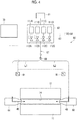
- FIG. 1 is a schematic configuration view of a forming device.
- a forming device 10 for forming a metal pipe 100 includes a blow forming die 13 including an upper die (first die) 12 and a lower die (second die) 11 which are paired with each other, a drive mechanism 80 which moves at least one of the upper die 12 and the lower die 11, a pipe holding mechanism (holding unit) 30 which holds a metal pipe material 14 between the upper die 12 and a lower die 11, a heating mechanism (heating unit) 50 which supplies power to the metal pipe material 14 held by the pipe holding mechanism 30 and heats the metal pipe material 14, a gas supply unit 60 which supplies a high-pressure gas (gas) into the metal pipe material 14 which is held between the upper die 12 and the lower die 11 and is heated, a pair of gas supply mechanisms 40 and 40 for supplying the gas from the gas supply unit 60 into the metal pipe material 14 held by the pipe holding mechanism 30, and a water circulation mechanism 72 which forcibly water-cools the
- the lower die (second die) 11 is fixed to a large base 15.
- the lower die 11 is configured of a large steel block and includes a cavity (recessed portion) 16 on an upper surface of the lower die 11.
- electrode receiving spaces 11a are provided around right and left ends (right and left ends in FIG. 1 ) of the lower die 11.
- the forming device 10 includes a first electrode 17 and a second electrode 18 which are configured so as to be movable upward or downward by an actuator (not shown) in the electrode receiving spaces 11a.
- Semicircular arc-shaped concave grooves 17a and 18a corresponding to a lower outer peripheral surface of the metal pipe material 14 are formed on upper surfaces of the first electrode 17 and the second electrode 18 (refer to FIG.
- a tapered concave surface 17b having a periphery inclined in a taper shape toward the concave groove 17a is formed on a front surface (a surface in an outside direction of the die) of the first electrode 17, and a tapered concave surface 18b having a periphery inclined in a taper shape toward the concave groove 18a is formed on a front surface (the surface in the outside direction of the die) of the second electrode 18.
- a cooling water passage 19 is formed in the lower die 11, and the lower die 11 includes a thermocouple 21 which is inserted from below at an approximately center. The thermocouple 21 is supported to be movable upward or downward by a spring 22.
- first and second electrodes 17 and 18 positioned on the lower die 11 side constitute the pipe holding mechanism 30, and can support the metal pipe material 14 between the upper die 12 and the lower die 11 such that the metal pipe material 14 can be lifted and lowered.
- the thermocouple 21 merely shows an example of temperature measuring means, and a non-contact type temperature sensor such as a radiant thermometer or a photo-thermometer may be used. If a correlation between an energization time and a temperature is obtained, it is sufficiently possible to eliminate the temperature measuring means.
- the upper die (first die) 12 includes a cavity (recessed portion) 24 on a lower surface and is a large steel block which houses a cooling water passage 25.
- a slide 82 is fixed to an upper end portion of the upper die 12.
- the slide 82 to which the upper die 12 is fixed is configured to be suspended by a pressurizing cylinder 26, and is guided by a guide cylinder 27 so as not to sway.
- electrode receiving spaces 12a are provided around right and left ends (right and left ends in FIG. 1 ) of the upper die 12.
- the forming device 10 includes a first electrode 17 and a second electrode 18 which are configured so as to be movable upward or downward by an actuator (not shown) in the electrode receiving spaces 12a.
- Semicircular arc-shaped concave grooves 17a and 18a corresponding to an upper outer peripheral surface of the metal pipe material 14 are formed on lower surfaces of the first electrode 17 and the second electrode 18 (refer to FIG. 3C ), and the metal pipe material 14 can be exactly fitted into the concave grooves 17a and 18a.
- a tapered concave surface 17b having a periphery inclined in a taper shape toward the concave groove 17a is formed on a front surface (a surface in the outside direction of the die) of the first electrode 17, and a tapered concave surface 18b having a periphery inclined in a taper shape toward the concave groove 18a is formed on a front surface (the surface in the outside direction of the die) of the second electrode 18.
- the pair of first and second electrodes 17 and 18 positioned on the upper die 12 side also constitutes the pipe holding mechanism 30, and if the metal pipe material 14 is clamped from above and below by a pair of upper and lower first and second electrodes 17 and 18, the upper and lower first and second electrodes 17 and 18 can exactly surround the outer periphery of the metal pipe material 14 so as to come into close contact with the entire circumference of the metal pipe material 14.
- the drive mechanism 80 includes the slide 82 which moves the upper die 12 such that the upper die 12 and the lower die 11 are joined to each other, a drive unit 81 which generates a driving force for moving the slide 82, and a servo motor 83 which controls a fluid volume with respect to the drive unit 81.
- the drive unit 81 is configured of a fluid supply unit which supplies a fluid (a working oil in a case where a hydraulic cylinder is adopted as the pressurizing cylinder 26) which drives the pressurizing cylinder 26 to the pressurizing cylinder 26.
- the controller 70 controls the servo motor 83 of the drive unit 81 so as to control an amount of the fluid supplied to the pressurizing cylinder 26, and thus, can control the movement of the slide 82.
- the drive unit 81 is not limited to one that applies the driving force to the slide 82 via the pressurizing cylinder 26 as described above.
- the drive unit 81 may be any one as long as it connects the drive mechanism to the slide 82 and directly or indirectly applies the driving force generated by the servo motor 83 to the slide 82.
- a drive mechanism which includes an eccentric shaft, a drive source (for example, a servo motor, a speed reducer, or the like) which applies a rotation force by which the eccentric shaft is rotated, a conversion unit (for example, a connecting rod, an eccentric sleeve, or the like) which converts a rotation motion of the eccentric shaft into a linear motion and moves the slide.
- a drive source for example, a servo motor, a speed reducer, or the like
- a conversion unit for example, a connecting rod, an eccentric sleeve, or the like
- the drive unit 81 may not include the servo motor 83.
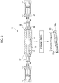
- FIG. 2 is a sectional view of the blow forming die 13 taken along line II-II shown in FIG. 1 . As shown in FIG. 2 , steps are provided on both the upper surface of the lower die 11 and the lower surface of the upper die 12.
- a surface of the center cavity 16 of the lower die 11 is defined as a reference line LV2
- the step is formed on the upper surface of the lower die 11 by a first protrusion 11b, a second protrusion 11c, a third protrusion 11d, and a fourth protrusion 11e.
- the first protrusion 11b and the second protrusion 11c are formed on a right side (a right side in FIG. 2 and a rear side of a paper surface in FIG. 2 ) of the cavity 16, and the third protrusion 11d and the fourth protrusion 11e are formed on a left side (a left side in FIG. 2 and a front side of the paper surface in FIG. 1 ) of the cavity 16.
- the second protrusion 11c is positioned between the cavity 16 and the first protrusion 11b.
- the third protrusion 11d is positioned between the cavity 16 and the fourth protrusion 11e.
- the second protrusion 11c and the third protrusion 11d respectively protrude toward the upper die 12 side from the first protrusion 11b and the fourth protrusion 11e.
- Protrusion amounts of the first protrusion 11b and the fourth protrusion 11e from the reference line LV2 are approximately the same as each other, and protrusion amounts of the second protrusion 11c and the third protrusion 11d from the reference line LV2 are approximately the same as each other.
- a surface of the center cavity 24 of the upper die 12 is defined as a reference line LV1
- the step is formed on the lower surface of the upper die 12 by a first protrusion 12b, a second protrusion 12c, a third protrusion 12d, and a fourth protrusion 12e.
- the first protrusion 12b and the second protrusion 12c are formed on a right side (a right side in FIG. 2 ) of the cavity 24, and the third protrusion 12d and the fourth protrusion 12e are formed on a left side (a left side in FIG. 2 ) of the cavity 24.
- the second protrusion 12c is positioned between the cavity 24 and the first protrusion 12b.
- the third protrusion 12d is positioned between the cavity 24 and the fourth protrusion 12e.
- the first protrusion 12b and the fourth protrusion 12e respectively protrude toward the lower die 11 side from the second protrusion 12c and the third protrusion 12d.
- Protrusion amounts of the first protrusion 12b and the fourth protrusion 12e from the reference line LV1 are approximately the same as each other, and protrusion amounts of the second protrusion 12c and the third protrusion 12d from the reference line LV1 are approximately the same as each other.
- the first protrusion 12b of the upper die 12 faces the first protrusion 11b of the lower die 11
- the second protrusion 12c of the upper die 12 faces the second protrusion 11c of the lower die 11
- the cavity 24 of the upper die 12 faces the cavity 16 of the lower die 11
- the third protrusion 12d of the upper die 12 faces the third protrusion 11d of the lower die 11
- the fourth protrusion 12e of the upper die 12 faces the fourth protrusion 11e of the lower die 11.
- a protrusion amount (a protrusion amount of the fourth protrusion 12e with respect to the third protrusion 12d) of the first protrusion 12b with respect to the second protrusion 12c in the upper die 12 is larger than a protrusion amount (a protrusion amount of the third protrusion 11d with respect to the fourth protrusion 11e) of the second protrusion 11c with respect to the first protrusion 11b in the lower die 11.
- a main cavity portion (first cavity portion) MC is formed between a surface (a surface becoming the reference line LV1) of the cavity 24 of the upper die 12 and a surface (a surface becoming the reference line LV2) of the cavity 16 of the lower die 11.
- a sub cavity portion (second cavity portion) SC1 which communicates with the main cavity portion MC and has a volume smaller than that of the main cavity portion MC is formed between the second protrusion 12c of the upper die 12 and the second protrusion 11c of the lower die 11.
- a sub cavity portion (second cavity portion) SC2 which communicates with the main cavity portion MC and has a volume smaller than that of the main cavity portion MC is formed between the third protrusion 12d of the upper die 12 and the third protrusion 11d of the lower die 11.
- the main cavity portion MC is a portion which forms a pipe portion 100a in the metal pipe 100 and sub cavity portions SC1 and SC2 are portions which respectively form flange portions 100b and 100c in the metal pipe 100 (refer to FIGS. 8C and 8D ).
- FIGS. 8C and 8D are portions which respectively form flange portions 100b and 100c in the metal pipe 100.
- the heating mechanism 50 includes a power supply 51, conducting wires 52 which extend from the power supply 51 and are connected to the first electrode 17 and the second electrode 18, and a switch 53 which is interposed between the conducting wires 52.
- the controller 70 controls the heating mechanism 50, and thus, the metal pipe material 14 can be heated to a quenching temperature (above an AC3 transformation point temperature).
- Each of the pair of gas supply mechanisms 40 includes a cylinder unit 42, a cylinder rod 43 which moves forward and rearward in accordance with an operation of the cylinder unit 42, and a seal member 44 connected to a tip of the cylinder rod 43 on the pipe holding mechanism 30 side.
- the cylinder unit 42 is placed on and fixed to the base 15 via a block 41.
- a tapered surface 45 is formed to be tapered.
- One tapered surface 45 is configured to have a shape which can be exactly fitted to the tapered concave surface 17b of the first electrode 17 so as to abut against the tapered concave surface 17b, and the other tapered surface 45 is configured to have a shape which can be exactly fitted to the tapered concave surface 18b of the second electrode 18 so as to abut against the tapered concave surface 17b (refer to FIG. 3A to 3C ).
- the seal member 44 extends from the cylinder unit 42 side toward the tip. More specifically, as shown in FIGS. 3A and 3B , a gas passage 46 through which a high-pressure gas supplied form the gas supply unit 60 flows is provided.
- the gas supply unit 60 includes a gas source 61, an accumulator 62 in which the gas supplied by the gas source 61 is stored, a first tube 63 which extends from the accumulator 62 to the cylinder unit 42 of the gas supply mechanism 40, a pressure control valve 64 and a switching valve 65 which are interposed in the first tube 63, a second tube 67 which extends from the accumulator 62 to the gas passage 46 formed in the seal member 44, and a pressure control valve 68 and a check valve 69 which are interposed in the second tube 67.
- the pressure control valve 64 plays a role of supplying gas of an operating pressure adapted to a pushing force of the seal member 44 with respect to the metal pipe material 14 to the cylinder unit 42.
- the check valve 69 plays a role of preventing the gas from back-flowing in the second tube 67.
- the accumulator 62 has gas tanks 111A to 111D which are gas storage means for storing the gas and on/off valves 112A to 112D whose on/off states are controlled by the controller 70.
- the gas tank 111A is connected to the gas source 61 and is connected to the second tube 67 via the on/off valve 112A.
- each of the gas tanks 111B to 111D is connected to the gas source 61 and is connected to the second tube 67 via the corresponding on/off valves 112B to 112D.
- the supply of the gas, which is supplied from the gas source 61 and stored in the gas tanks 111A to 111D, to the second tube 67 is controlled by the corresponding on/off valves 112A to 112D.
- the on/off valves 112A to 112D are controlled independently by the controller 70.
- the pressures of the gases stored in the gas tanks 111A and 111B are the same as each other, and the pressures of the gases stored in the gas tanks 111C and 111D are the same as each other.
- the gas stored in the gas tanks 111A and 111B is a gas (hereinafter, referred to as a low-pressure gas) having an operating pressure for expanding portions 14a and 14b (refer to FIGS. 8B ) of the metal pipe material 14.
- the gas stored in the gas tanks 111C and 111D is a gas (hereinafter, referred to as a high-pressure gas) having an operating pressure for forming the pipe portion 100a (refer to FIG. 8D ) of the metal pipe 100.
- the pressure (first pressure P1 refer to FIG.
- each of the first pressure P1 and the second pressure P2 may not be a pressure value indicating a certain point.
- each of the first pressure P1 and the second pressure P2 is within a range of 80% to 120% from a reference pressure value.
- the first pressure P1 is within a range of 8 MPa to 12 MPa.
- the second tube 67 branches off from the check valve 69 in two branches, and includes a first supply line L1 which extends to one gas supply mechanism 40 and a second supply line L2 which extends to the other gas supply mechanism 40.
- a pressure sensor 91 for detecting the pressure of the gas flowing through the lines L1 and L2 is attached to each of the first supply line L1 and the second supply line L2.
- the controller 70 controls on/off of the on/off valves 112A to 112D of the accumulator 62 and on/off of the pressure control valve 68 according to a pressure change of the gas detected by the pressure sensor 91.
- the controller 70 intermittently switches the on/off of the on/off valves 112A to 112D based on a detection result of the pressure sensor 91 so as to control the gas supply of the gas supply unit 60.
- the controller 70 controls the gas supply of the gas supply unit 60 such that the pressure of the gas in the metal pipe material 14 at the time of the expansion is maintained at the first pressure P1 or the second pressure P2.
- the controller 70 controls the pressure control valve 68 such that the pressure control valve 68 is turned off.
- the controller 70 controls the pressure control valve 68 such that the pressure control valve 68 is turned on.
- the water circulation mechanism 72 includes a water tank 73 which stores water, a water pump 74 which pumps up the water stored in the water tank 73, pressurizes the water, and feeds the pressurized water to the cooling water passage 19 of the lower die 11 and the cooling water passage 25 of the upper die 12, and a pipe 75.
- a cooling tower for lowering a water temperature and a filter for purifying the water may be interposed in the pipe 75.
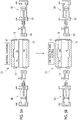
- FIG. 5 shows steps from a pipe charging step of charging the metal pipe material 14 as a material to an energizing/heating step of energizing and heating the metal pipe material 14.
- the metal pipe material 14 of a hardenable steel type is prepared.
- the metal pipe material 14 is placed on (charged in) the first and second electrodes 17 and 18, which are provided on the lower die 11 side, using a robot arm or the like.
- the concave grooves 17a and 18a are respectively formed on the first and second electrodes 17 and 18, and thus, the metal pipe material 14 is positioned by the concave grooves 17a and 18a.
- the controller 70 controls the pipe holding mechanism 30, and thus, the metal pipe material 14 is held by the pipe holding mechanism 30.
- an actuator (not shown) which can move the first electrode 17 and the second electrode 18 forward or rearward is operated, and thus, the first and second electrodes 17 and 18 positioned above and below approach each other and abut against each other. According to this abutment, both end portions of the metal pipe material 14 are clamped from above and below by the first and second electrodes 17 and 18.
- this clamping is performed in an aspect in which the concave grooves 17a and 18a respectively formed on the first and second electrodes 17 and 18 are provided such that the first and second electrodes 17 and 18 come into close contact with the entire circumference of the metal pipe material 14.
- the present invention is not limited to the configuration in which the first and second electrodes 17 and 18 come into close contact with the entire circumference of the metal pipe material 14. That is, the first and second electrodes 17 and 18 may abut against a portion of the metal pipe material 14 in the circumferential direction.
- the controller 70 controls the heating mechanism 50 so as to heat the metal pipe material 14. Specifically, the controller 70 turns on the switch 53 of the heating mechanism 50. Accordingly, power from the power supply 51 is supplied to the metal pipe material 14, and the metal pipe material 14 itself is heated (Joule heat) by a resistance existing in the metal pipe material 14. In this case, a measurement value of the thermocouple 21 is always monitored, and the energization is controlled based on this result.
- FIG. 6 is a view showing an outline of a blow forming step performed by the forming device and a flow after the blow forming step.
- the blow forming die 13 is closed with respect to the heated metal pipe material 14, and the metal pipe material 14 is disposed in the cavity of the blow forming die 13 and is sealed.
- the cylinder unit 42 of the gas supply mechanism 40 is operated, and thus, both ends of the metal pipe material 14 are sealed by the seal members 44 (also refer to FIGS. 3A to 3C ).
- the blow forming die 13 is closed, the gas is sucked into the metal pipe material 14, and the heated and softened metal pipe material 14 is formed according to a shape of the cavity (a specific forming method of the metal pipe material 14 will be described later).
- the metal pipe material 14 is heated to a high temperature (approximately 950°c) and softened, and thus, the gas supplied into the metal pipe material 14 thermally expands. Accordingly, for example, the supplied gas serves as compressed air or compressed nitrogen gas, the metal pipe material 14 having a temperature of 950°C is easily expanded by the compressed air which is thermally expanded, and the metal pipe 100 can be obtained.
- a high temperature approximately 950°c
- the supplied gas serves as compressed air or compressed nitrogen gas
- the metal pipe material 14 having a temperature of 950°C is easily expanded by the compressed air which is thermally expanded, and the metal pipe 100 can be obtained.
- an outer peripheral surface of the blow-formed and expanded metal pipe material 14 comes into contact with the cavity 16 of the lower die 11 so as to be rapidly cooled and comes into contact with the cavity 24 of the upper die 12 so as to be rapidly cooled (the upper die 12 and the lower die 11 have a large heat capacity and are controlled to a low temperature, and thus, if the metal pipe material 14 comes into contact with the upper die 12 and the lower die 11, a heat of a pipe surface is taken to the die side at once), and thus, hardening is performed on the metal pipe material 14.
- the above-described cooling method is referred to as die contact cooling or die cooling.
- austenite transforms into martensite (hereinafter, transformation from austenite to martensite is referred to as martensitic transformation).
- the cooling rate decreased in a second half of the cooling, and thus, martensite transforms into another structure (such as troostite, sorbite, or the like) due to recuperation. Therefore, it is not necessary to separately perform tempering treatment.
- the cooling may be performed by supplying a cooling medium to the metal pipe 100, instead of or in addition to the cooling of the die.
- the metal pipe material 14 comes into contact with the die (upper die 12 and lower die 11) until a temperature at which the martensitic transformation starts, and thereafter, the die is opened and a cooling medium (cooling gas) is blown onto the metal pipe material 14, and thus, the martensitic transformation is generated.
- a cooling medium cooling gas
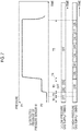
- FIG. 7 is a timing chart showing a relationship between a detected pressure of the pressure sensor and the gas supply in the blow forming step performed by the forming device.
- (a) shows a temporal change of the detected pressure of the pressure sensor 91
- (b) shows a supply timing of the low-pressure gas
- (c) shows a supply timing of the high-pressure gas.
- the heated metal pipe material 14 is prepared between the cavity 24 of the upper die 12 and the cavity 16 of the lower die 11.
- the metal pipe material 14 is supported by the second protrusion 11c and the third protrusion 11d of the lower die 11.
- a distance between the second protrusion 12c of the upper die 12 and the second protrusion 11c of the lower die 11 in the period T1 is D1 (see FIG. 8A ).
- the drive mechanism 80 moves the upper die 12 in a direction in which the upper die 12 is to be joined to the lower die 11.
- the upper die 12 and the lower die 11 are not completely closed, and a distance between the second protrusion 12c of the upper die 12 and the second protrusion 11c of the lower die 11 is D2 (D2 ⁇ D1).
- the main cavity portion MC is formed between the surface of the reference line LV1 of the cavity 24 and the surface of the reference line LV2 of the cavity 16.
- the sub cavity portion SC1 is formed between the second protrusion 12c of the upper die 12 and the second protrusion 11c of the lower die 11, and the sub cavity portion SC2 is formed between the third protrusion 12d of the upper die 12 and the third protrusion 11d of the lower die 11.
- the main cavity portion MC and the sub-cavity portions SC1 and SC2 are in a state of communicating with each other.
- an inner edge of the first protrusion 12b of the upper die 12 and an outer edge of the second protrusion 11c of the lower die 11 come into close contact with each other
- an inner edge of the fourth protrusion 12e of the upper die 12 and an outer edge of the third protrusion 11d of the lower die 11 come into close contact with each other, and thus, the main cavity portion MC and the sub cavity portions SC1 and SC2 are sealed to the outside.
- a space (clearance) is provided between the first protrusion 12b of the upper die 12 and the first protrusion 11b of the lower die 11
- a space (clearance) is provided between the fourth protrusion 12e of the upper die 12 and the fourth protrusion 11e of the lower die 11, respectively.
- the low-pressure gas is supplied to the inside of the metal pipe material 14 softened by heating of the heating mechanism 50 through the gas supply unit 60.
- This low-pressure gas is the gas accumulated in the gas tanks 111A and 111B provided in the accumulator 62 of the gas supply unit 60.
- the supply of the low-pressure gas by the gas supply unit 60 is controlled by the on/off valves 112A and 112B and the pressure control valve 68. In this case, under the control of the controller 70, the gas supply unit 60 intermittently supplies the low-pressure gas into the metal pipe material 14 so as to maintain the pressure of the low-pressure gas detected by the pressure sensor 91 at the second pressure P2.
- the metal pipe material 14 expands in the main cavity portion MC as shown in FIG. 8B .
- portions (both side portions) 14a and 14b of the metal pipe material 14 expands so as to enter the sub-cavity portions SC1 and SC2 communicating with the main cavity portion MC, respectively.
- the upper die 12 is moved by the drive mechanism 80. More specifically, the upper die 12 is moved by the drive mechanism 80, and as shown in FIG. 8C , the upper die 12 and the lower die 11 are fitted (clamped) to each other such that a distance between the second protrusion 12c of the upper die 12 and the second protrusion 11c of the lower die 11 is D3 (D3 ⁇ D2).
- the first protrusion 12b of the upper die 12 and the first protrusion 11b of the lower die 11 come into close contact with each other without gaps
- the fourth protrusion 12e of the upper die 12 and the fourth protrusion 11e of the lower die 11 come into close contact with each other without gaps.
- portions 14a and 14b of the expanded metal pipe material 14 is pressed by the upper die 12 and the lower die 11 to form the flange portion 100b of the metal pipe 100 in the sub cavity portion SC1 and the flange portion 100c of the metal pipe 100 in the sub cavity portion SC2.
- the flange portions 100b and 100c are formed by folding a portion of the metal pipe material 14 along a longitudinal direction of the metal pipe 100 (refer to FIG. 6 ).
- the high-pressure gas is supplied to the inside of the metal pipe material 14 by the gas supply unit 60.
- This high-pressure gas is the gas accumulated in the gas tanks 111C and 111D of the accumulator 62 of the gas supply unit 60.
- the supply of the high-pressure gas by the gas supply unit 60 is controlled by on/off valves 112C and 112D and the pressure control valve 68. In this case, under the control of the controller 70, the gas supply unit 60 intermittently supplies the high-pressure gas into the metal pipe material 14 so that the pressure of the high-pressure gas detected by the pressure sensor 91 is maintained at the first pressure P1.
- the metal pipe material 14 in the main cavity portion MC expands and the pipe portion 100a of the metal pipe 100 is formed as shown in FIG. 8D .
- a supply time of the high-pressure gas in the period T5 is longer than a supply time of the low-pressure gas in the period T3. Accordingly, the metal pipe material 14 expands sufficiently to reach every corner of the main cavity portion MC, and the pipe portion 100a follows the shape of the main cavity portion MC defined by the upper die 12 and the lower die 11.
- a time from the blow forming of the metal pipe material 14 to the completion of the formation of the metal pipe 100 is approximately several seconds to several tens of seconds depending on the type of the metal pipe material 14.
- the main cavity portion MC is formed in a rectangular cross section, and thus, the metal pipe material 14 is blow-formed according to the shape such that the pipe portion 100a is formed in a rectangular tubular shape.
- the shape of the main cavity portion MC is not particularly limited, and any shape such as a circular cross section, an elliptical cross section, or a polygonal cross section may be adopted according to a desired shape.
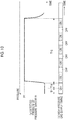
- a controller of a forming device according to the comparative example controls to supply a low-pressure gas and a high-pressure gas by a gas supply unit until the lower-pressure gas and the high-pressure gas respectively reach predetermined values. Accordingly, as shown in FIG. 9 , in the period T3 in the comparative example, the pressure in the metal pipe material 14 is temporarily set to the second pressure P2, and thereafter, the gas supply of the gas supply unit is stopped. That is, even if the pressure in the metal pipe material 14 subsequently falls outside a range of the second pressure P2, the gas supply unit does not perform the gas supply again.
- the expansion amounts of the portions 14a and 14b of the metal pipe material 14 entering the sub-cavity portions SC1 and SC2 are smaller than those of the forming method of the present embodiment. Accordingly, if the small expanded portions 14a and 14b of the metal pipe material 14 are pressed by the upper die 12 and the lower die 11, the flange portions 100b and 100c do not have sufficient sizes.
- the pressure in the metal pipe material 14 is temporarily set to the first pressure P1, and thereafter, the gas supply of the gas supply unit is stopped. That is, after the pressure in the metal pipe material 14 is temporarily set to the first pressure P1, even when the pressure in the metal pipe material 14 subsequently falls outside a range of the first pressure P1, the gas supply unit does not perform the gas supply again.
- a force for pressing the pipe portion against the first and second dies by the gas decreases in accordance with a pressure drop of the gas in the pipe portion 100a of the metal pipe 100 formed in the main cavity portion MC. Accordingly, when the hardening of the pipe portion 100a is performed by the upper die 12 and the lower die 11, adhesion between the metal pipe 100, and the upper die 12 and the lower die 11 decreases, and variations in hardenability of the metal pipe 100 occur.
- the controller 70 controls the gas supply is controlled so as to maintain the pressure in the metal pipe material 14 at the first pressure P1. Accordingly, it possible to prevent pressure drop in the pipe portion 100a caused by cooling of the pipe portion 100a due to a contact between the upper die 12 and the lower die 11 forming the main cavity portion MC, and the pipe portion 100a. The pressure drop in the pipe portion 100a is prevented, and thus, it is possible to suppress a decrease in a force for pressing the pipe portion 100a against the upper die 12 and the lower die 11.
- the metal pipe 100 when the metal pipe 100 is formed, it is possible to suppress the decrease in the adhesion between the pipe portion 100a, and the upper die 12 and the lower die 11, and it is possible to suppress occurrence of variations in hardenability in the pipe portion 100a of the metal pipe 100.
- the upper die 12 and the lower die 11 constitutes the sub cavity portions SC1 and SC2 which communicate with the main cavity portion MC so as to form the flange portions 100b and 100c of the metal pipe 100, in addition to the main cavity portion MC, and the controller 70 controls the gas supply of the gas supply unit 60 so as to expand the portions 14 and 14b of the metal pipe material 14 into the sub cavity portions SC1 and SC2 when the flange portions 100b and 100c are formed from the metal pipe material 14 before the pipe portion 100a is formed.
- the portions 14a and 14b of the metal pipe material 14 in the sub cavity portions SC1 and SC2 are respectively expanded before the pipe portion 100a is formed, the expanded portions 14a and 14b of the metal pipe material 14 are pressed by the upper die 12 and the lower die 11, and it is possible to form the flange portions 100b and 100c. Accordingly, it is possible to easily form the flange portions 100b and 100c and the pipe portion 100a having a desired shape.
- the controller 70 controls the gas supply of the gas supply unit 60 to expand the portions 14a and 14b of the metal pipe material 14 so as to form the flange portions 100b and 100c
- the controller 70 controls the gas supply of the gas supply unit 60 so as to maintain the pressure of the low-pressure gas in the metal pipe material 14 at the second pressure P2 lower than the first pressure P1. Accordingly, the expansion amounts of the portions 14a and 14b of the metal pipe material 14 can be easily adjusted by the stabilized low-pressure gas, and the flange portions 100b and 100c can be formed so as to have a desired size.
- the pipe portion 100a having a desired shape can be formed by the high-pressure gas regardless of the flange portions 100b and 100c. Accordingly, it is possible to more easily form the flange portion 100b and 100c and the pipe portion 100a having a desired shape.
- the controller 70 controls the gas supply unit 60 so as to intermittently supply the gas. Accordingly, the pressure of the gas in the metal pipe material 14 can be easily maintained at the first pressure P1 or the second pressure P2.
- the gas supply unit 60 includes the gas tanks 111A to 111D serving as the gas storage means for storing the gas, and the controller 70 supplies the gas stored in at least one of the gas tanks 111C and 111D into the metal pipe material 14 so as to maintain the pressure of the gas in the metal pipe material 14 at the first pressure P1. Accordingly, the pressure of the gas in the metal pipe material 14 can be easily maintained at the first pressure P1.
- a forming method of a metal pipe 100A (refer to FIG. 11C ) which does not have the flange portions 100b and 100c will be described.
- the lower die 11 which does not have the first protrusion 11b, the second protrusion 11c, the third protrusion 11d, and the fourth protrusion 11e and the upper die 12 which does not have the first protrusion 12b, the second protrusion 12c, the third protrusion 12d, and the fourth protrusion 12e are used.
- the flange portions are not provided in the metal pipe 100A, and thus, the accumulator 62 may not have the gas tanks 111A and 111B and the on/off valves 112A and 112B.
- the heated metal pipe material 14 is provided between the cavity 24 of the upper die 12 and the cavity 16 of the lower die 11.
- the metal pipe material 14 is placed on the cavity 24 of the lower die 11.
- the drive mechanism 80 moves the upper die 12 in the direction in which the upper die 12 is to be joined to the lower die 11. Accordingly, as shown in FIG. 11B , the upper die 12 and the lower die 11 come into close contact with each other, and thus, the sealed main cavity portion MC is formed.
- the high-pressure gas is supplied into the metal pipe material 14 by the gas supply unit 60.
- the high-pressure gas is intermittently supplied to the metal pipe material 14 so as to maintain the pressure in the metal pipe material 14 at the first pressure P1.
- the metal pipe material 14 in the main cavity portion MC expands, and as shown in FIG. 11C , the metal pipe 100A which does not have the flange portions is formed.
- the high-pressure gas is intermittently supplied into the metal pipe material 14, and thus, it is possible to prevent the pressure drop in the metal pipe 100A, and it is possible to suppress a decrease in the force for pressing the metal pipe 100A against the upper die 12 and the lower die 11. Accordingly, it is possible to suppress occurrence of variations in hardenability in the metal pipe 100A.
- the present invention is not limited to the embodiments at all.
- the forming device 10 does not necessarily have the heating mechanism 50, and the metal pipe material 14 may be heated in advance.
- the gas supply of the gas supply unit 60 may not be intermittently controlled under the control of the controller 70, or may be continuous. In a case where the gas supply of the gas supply unit 60 is continuously performed, it is preferable to control the pressure in the pipe portion 100a by the pressure control valve 68 or the like.
- the gas supply of the gas supply unit 60 may be controlled. That is, in the period T3, the controller 70 may control the gas supply of the gas supply unit 60 such that the gas supply is performed until the gas supply reaches a predetermined value.
- the gas source 61 may have both a high-pressure gas source for supplying the high-pressure gas and a low-pressure gas source for supplying the low-pressure gas.
- the gas may be supplied from the high-pressure gas source or the low-pressure gas source to the gas supply mechanism 40 according to a situation by controlling the gas source 61 of the gas supply unit 60 by the controller 70.
- the accumulator 62 (or the gas tanks 111A to 111D) may not be included in the gas supply unit 60.
- the accumulator 62 has the four gas tanks 111A to 111D, the number of the gas tanks provided in the accumulator 62 may be three or less, or five or more.
- the pressures of the gases stored in the gas tanks 111A to 111D may all be the first pressure P1. In this case, in the period T3, for example, the portions 14a and 14b of the metal pipe material 14 may be expanded using the low-pressure gas source.
- the lower die 11 may be moved.
- the lower die 11 is not fixed to the base 15 but is attached to the slide of the drive mechanism 80.
- the metal pipe 100 may have the flange portion on one side thereof.
- one sub cavity portion formed by the upper die 12 and the lower die 11 is provided.
- the metal pipe material 14 prepared between the upper die 12 and the lower die 11 may have a cross-sectional elliptical shape in which a diameter in a right-left direction is larger than a diameter in an up-down direction. Accordingly, a portion of the metal pipe material 14 may be made to easily enter the sub-cavity portions SC1 and SC2.
- the metal pipe material 14 may be bent (pre-bent) in advance along the axial direction. In this case, the formed metal pipe 100 has the flange portion and is formed in a bent cylindrical shape.
Landscapes
- Engineering & Computer Science (AREA)
- Mechanical Engineering (AREA)
- Physics & Mathematics (AREA)
- Fluid Mechanics (AREA)
- Shaping Metal By Deep-Drawing, Or The Like (AREA)
Claims (6)
- Formungsvorrichtung (10) zum Formen eines Metallrohres, das einen Rohrabschnitt aufweist, umfassend:ein erstes Werkzeug (12) und ein zweites Werkzeug (11), die miteinander gepaart sind und einen ersten Höhlungsabschnitt zum Formen des Rohrabschnitts bilden,einen Antriebsmechanismus (80), der wenigstens eines von dem ersten Werkzeug (12) und dem zweiten Werkzeug (11) in einer Richtung bewegt, in der die Werkzeuge miteinander verbunden werden sollen,eine Gaszufuhreinheit (60), die ein Gas in ein Metallrohrmaterial (14) zuführt, das zwischen dem ersten Werkzeug (12) und dem zweiten Werkzeug (11) gehalten und erhitzt wird, undeine Steuerung (70), die den Antrieb des Antriebsmechanismus (80) und die Gaszufuhr der Gaszufuhreinheit (60) steuert,dadurch gekennzeichnet, dass:
die Steuerung (70) die Gaszufuhr der Gaszufuhreinheit (60) so steuert, um während eines Härtungszeitraums, in dem das erste und das zweite Werkzeug (11, 12) gekühlt werden und das Metallrohrmaterial (14) in dem Metallrohrmaterial (14) gehärtet wird, und wenn das Gas von der Gaszufuhreinheit (60) in das Metallrohrmaterial (14) zugeführt wird und das Metallrohrmaterial (14) in dem ersten Höhlungsabschnitt in einem Zustand, in dem das erste Werkzeug (12) und das zweite Werkzeug (11) miteinander verbunden sind, zu dem Rohrabschnitt geformt wird, einen Druck in dem Metallrohrmaterial (14) bei einem ersten Druck zu halten. - Formungsvorrichtung (10) nach Anspruch 1,
wobei das erste Werkzeug (12) und das zweite Werkzeug (11), zusätzlich zu dem ersten Höhlungsabschnitt, einen zweiten Höhlungsabschnitt bilden, der mit dem ersten Höhlungsabschnitt in Verbindung steht, um so einen Flanschabschnitt des Metallrohres zu formen, und
wobei die Steuerung (70) die Gaszufuhr der Gaszufuhreinheit (60) so steuert, um einen Abschnitt des Metallrohrmaterials (14) in dem zweiten Höhlungsabschnitt zu expandieren, wenn der Flanschabschnitt aus dem Metallrohrmaterial (14) geformt wird, bevor der Rohrabschnitt geformt wird. - Formungsvorrichtung (10) nach Anspruch 2,
wobei, wenn die Steuerung (70) die Gaszufuhr der Gaszufuhreinheit (60) so steuert, um einen Abschnitt des Metallrohrmaterials (14) zu expandieren, um den Flanschabschnitt zu formen, die Steuerung (70) die Gaszufuhr der Gaszufuhreinheit (60) so steuert, um den Druck des Gases in dem Metallrohrmaterial (14) bei einem zweiten Druck zu halten, der niedriger ist als der erste Druck. - Formungsvorrichtung (10) nach einem der Ansprüche 1 bis 3,
wobei, wenn das Gas von der Gaszufuhreinheit (60) in das Metallrohrmaterial (14) zugeführt wird, die Steuerung (70) die Gaszufuhreinheit (60) so steuert, um das Gas intermittierend zuzuführen. - Formungsvorrichtung (10) nach einem der Ansprüche 1 bis 4,
wobei die Gaszufuhreinheit (60) Gasspeichermittel zum Speichern des Gases umfasst und
wobei die Steuerung (70) das in den Gasspeichermitteln gespeicherte Gas so in das Metallrohrmaterial (14) zuführt, um den Druck des Gases in dem Metallrohrmaterial (14) bei dem ersten Druck zu halten. - Formungsverfahren zum Formen eines Metallrohres, das einen Rohrabschnitt aufweist, wobei das Verfahren umfasst:Vorbereiten eines erhitzten Metallrohrmaterials (14) zwischen einem ersten Werkzeug (12) und einem zweiten Werkzeug (11),Bilden eines ersten Höhlungsabschnitts zum Ausbilden des Rohrabschnitts zwischen dem ersten Werkzeug (12) und dem zweiten Werkzeug (11) durch Bewegen wenigstens eines von dem ersten Werkzeug (12) und dem zweiten Werkzeug (11) in einer Richtung, in der die Werkzeuge miteinander verbunden werden sollen,wobei das Verfahren dadurch gekennzeichnet ist, dass es ferner umfasst:
Formen des Rohrabschnitts in dem ersten Höhlungsabschnitt durch Zuführen von Gas, um so während eines Härtungszeitraums, in dem das erste und das zweite Werkzeug (11, 12) gekühlt werden und das Metallrohrmaterial (14) gehärtet wird, einen Druck in dem Metallrohrmaterial (14) bei einem ersten Druck zu halten.
Applications Claiming Priority (2)
| Application Number | Priority Date | Filing Date | Title |
|---|---|---|---|
| JP2016038796 | 2016-03-01 | ||
| PCT/JP2017/004546 WO2017150110A1 (ja) | 2016-03-01 | 2017-02-08 | 成形装置及び成形方法 |
Publications (3)
| Publication Number | Publication Date |
|---|---|
| EP3424607A1 EP3424607A1 (de) | 2019-01-09 |
| EP3424607A4 EP3424607A4 (de) | 2019-04-10 |
| EP3424607B1 true EP3424607B1 (de) | 2020-11-18 |
Family
ID=59744028
Family Applications (1)
| Application Number | Title | Priority Date | Filing Date |
|---|---|---|---|
| EP17759581.6A Active EP3424607B1 (de) | 2016-03-01 | 2017-02-08 | Formvorrichtung und formverfahren |
Country Status (6)
| Country | Link |
|---|---|
| US (1) | US11267034B2 (de) |
| EP (1) | EP3424607B1 (de) |
| JP (1) | JP6860548B2 (de) |
| CN (1) | CN108698106B (de) |
| CA (1) | CA3015996C (de) |
| WO (1) | WO2017150110A1 (de) |
Families Citing this family (11)
| Publication number | Priority date | Publication date | Assignee | Title |
|---|---|---|---|---|
| JP6771271B2 (ja) * | 2015-03-31 | 2020-10-21 | 住友重機械工業株式会社 | 成形装置 |
| JP7080085B2 (ja) * | 2018-03-28 | 2022-06-03 | 住友重機械工業株式会社 | 成形装置 |
| CN108526284A (zh) * | 2018-04-18 | 2018-09-14 | 保隆(安徽)汽车配件有限公司 | 一种管件内高压外低压成型方法及成型机 |
| CA3101330C (en) * | 2018-08-01 | 2023-01-10 | Sumitomo Heavy Industries, Ltd. | Reinforcement member for vehicle, and method for manufacturing same |
| JP7240411B2 (ja) * | 2018-10-01 | 2023-03-15 | 住友重機械工業株式会社 | 膨張成形装置 |
| KR102786973B1 (ko) * | 2018-10-11 | 2025-03-27 | 현대자동차주식회사 | 전단장치 및 이를 이용한 알루미늄 전단방법 |
| JP2022062292A (ja) * | 2019-03-05 | 2022-04-20 | 住友重機械工業株式会社 | 成形装置及び成形方法 |
| JP2020157354A (ja) * | 2019-03-27 | 2020-10-01 | 住友重機械工業株式会社 | 金属パイプ及び金属パイプの成形方法 |
| CN110586684B (zh) * | 2019-10-25 | 2020-09-22 | 大连理工大学 | 一种大尺寸薄壁环壳充气热压弯成形装置和方法 |
| JP7286571B2 (ja) * | 2020-03-02 | 2023-06-05 | 住友重機械工業株式会社 | 成形装置、及び成形方法 |
| JP7763583B2 (ja) * | 2020-04-27 | 2025-11-04 | 住友重機械工業株式会社 | 車両用構造体 |
Family Cites Families (14)
| Publication number | Priority date | Publication date | Assignee | Title |
|---|---|---|---|---|
| GB9727063D0 (en) * | 1997-12-23 | 1998-02-18 | Gkn Sankey Ltd | A hydroforming process |
| US6322645B1 (en) * | 1999-09-24 | 2001-11-27 | William C. Dykstra | Method of forming a tubular blank into a structural component and die therefor |
| JP3820885B2 (ja) * | 2000-01-14 | 2006-09-13 | 住友金属工業株式会社 | 液圧バルジ加工部品の成形方法、金型および液圧バルジ加工部品 |
| JP3482522B2 (ja) | 2000-10-24 | 2003-12-22 | 川崎重工業株式会社 | 高温バルジ成形装置 |
| JP3761820B2 (ja) * | 2001-09-04 | 2006-03-29 | アイシン高丘株式会社 | 金属部材成形方法 |
| JP4933788B2 (ja) * | 2006-02-13 | 2012-05-16 | 本田技研工業株式会社 | バルジ成形方法及び中空成形体 |
| WO2009014233A1 (ja) * | 2007-07-20 | 2009-01-29 | Nippon Steel Corporation | ハイドロフォーム加工方法及びハイドロフォーム加工部品 |
| JP4920772B2 (ja) * | 2010-06-18 | 2012-04-18 | リンツリサーチエンジニアリング株式会社 | フランジ付金属製パイプ製造装置及びその製造方法並びにブロー成形金型 |
| JP5855914B2 (ja) | 2011-11-15 | 2016-02-09 | マツダ株式会社 | 液圧成形方法 |
| BR112014016331B1 (pt) | 2011-12-30 | 2020-07-21 | The Coca-Cola Company | método e sistema para a fabricação de um recipiente metálico |
| JP6326224B2 (ja) | 2013-12-09 | 2018-05-16 | 住友重機械工業株式会社 | 成形装置 |
| CN104525676B (zh) * | 2014-12-08 | 2017-03-22 | 无锡朗贤汽车组件研发中心有限公司 | 硼钢钢管的气胀热成形分段强化工艺 |
| CN104525675B (zh) * | 2014-12-08 | 2017-03-22 | 无锡朗贤汽车组件研发中心有限公司 | 硼钢钢管的气胀热成形工艺 |
| JP6670543B2 (ja) * | 2014-12-11 | 2020-03-25 | 住友重機械工業株式会社 | 成形装置及び成形方法 |
-
2017
- 2017-02-08 EP EP17759581.6A patent/EP3424607B1/de active Active
- 2017-02-08 CA CA3015996A patent/CA3015996C/en active Active
- 2017-02-08 WO PCT/JP2017/004546 patent/WO2017150110A1/ja not_active Ceased
- 2017-02-08 CN CN201780014553.4A patent/CN108698106B/zh active Active
- 2017-02-08 JP JP2018502981A patent/JP6860548B2/ja active Active
-
2018
- 2018-08-28 US US16/115,034 patent/US11267034B2/en active Active
Non-Patent Citations (1)
| Title |
|---|
| None * |
Also Published As
| Publication number | Publication date |
|---|---|
| CN108698106A (zh) | 2018-10-23 |
| US11267034B2 (en) | 2022-03-08 |
| JP6860548B2 (ja) | 2021-04-14 |
| US20180361458A1 (en) | 2018-12-20 |
| CN108698106B (zh) | 2020-04-24 |
| JPWO2017150110A1 (ja) | 2018-12-27 |
| EP3424607A4 (de) | 2019-04-10 |
| EP3424607A1 (de) | 2019-01-09 |
| CA3015996A1 (en) | 2017-09-08 |
| CA3015996C (en) | 2023-12-12 |
| WO2017150110A1 (ja) | 2017-09-08 |
Similar Documents
| Publication | Publication Date | Title |
|---|---|---|
| EP3424607B1 (de) | Formvorrichtung und formverfahren | |
| EP3597323B1 (de) | Formvorrichtung und formverfahren | |
| CN110038951B (zh) | 成型装置 | |
| CN106536080B (zh) | 成型装置及成型方法 | |
| EP3305430B1 (de) | Formvorrichtung | |
| JP2016002587A (ja) | 成形システム | |
| US11253900B2 (en) | Forming apparatus | |
| EP3159150B1 (de) | Formsystem | |
| JP2016002586A (ja) | 成形システム | |
| JP2018001210A (ja) | 成形装置 | |
| CA3052835C (en) | Forming device and forming method | |
| WO2020179359A1 (ja) | 成形装置及び成形方法 |
Legal Events
| Date | Code | Title | Description |
|---|---|---|---|
| STAA | Information on the status of an ep patent application or granted ep patent |
Free format text: STATUS: THE INTERNATIONAL PUBLICATION HAS BEEN MADE |
|
| PUAI | Public reference made under article 153(3) epc to a published international application that has entered the european phase |
Free format text: ORIGINAL CODE: 0009012 |
|
| STAA | Information on the status of an ep patent application or granted ep patent |
Free format text: STATUS: REQUEST FOR EXAMINATION WAS MADE |
|
| 17P | Request for examination filed |
Effective date: 20180910 |
|
| AK | Designated contracting states |
Kind code of ref document: A1 Designated state(s): AL AT BE BG CH CY CZ DE DK EE ES FI FR GB GR HR HU IE IS IT LI LT LU LV MC MK MT NL NO PL PT RO RS SE SI SK SM TR |
|
| AX | Request for extension of the european patent |
Extension state: BA ME |
|
| STAA | Information on the status of an ep patent application or granted ep patent |
Free format text: STATUS: EXAMINATION IS IN PROGRESS |
|
| A4 | Supplementary search report drawn up and despatched |
Effective date: 20190314 |
|
| RIC1 | Information provided on ipc code assigned before grant |
Ipc: B21D 26/043 20110101ALI20190307BHEP Ipc: B21D 22/02 20060101ALI20190307BHEP Ipc: B21D 37/16 20060101ALI20190307BHEP Ipc: B21D 26/039 20110101ALN20190307BHEP Ipc: B21D 26/041 20110101AFI20190307BHEP Ipc: B21D 19/08 20060101ALI20190307BHEP |
|
| 17Q | First examination report despatched |
Effective date: 20190326 |
|
| DAV | Request for validation of the european patent (deleted) | ||
| DAX | Request for extension of the european patent (deleted) | ||
| GRAP | Despatch of communication of intention to grant a patent |
Free format text: ORIGINAL CODE: EPIDOSNIGR1 |
|
| STAA | Information on the status of an ep patent application or granted ep patent |
Free format text: STATUS: GRANT OF PATENT IS INTENDED |
|
| RIC1 | Information provided on ipc code assigned before grant |
Ipc: B21D 26/043 20110101ALI20200701BHEP Ipc: B21D 26/041 20110101AFI20200701BHEP Ipc: B21D 26/039 20110101ALN20200701BHEP Ipc: B21D 22/02 20060101ALI20200701BHEP Ipc: B21D 37/16 20060101ALI20200701BHEP Ipc: B21D 19/08 20060101ALI20200701BHEP |
|
| INTG | Intention to grant announced |
Effective date: 20200728 |
|
| GRAS | Grant fee paid |
Free format text: ORIGINAL CODE: EPIDOSNIGR3 |
|
| GRAA | (expected) grant |
Free format text: ORIGINAL CODE: 0009210 |
|
| STAA | Information on the status of an ep patent application or granted ep patent |
Free format text: STATUS: THE PATENT HAS BEEN GRANTED |
|
| AK | Designated contracting states |
Kind code of ref document: B1 Designated state(s): AL AT BE BG CH CY CZ DE DK EE ES FI FR GB GR HR HU IE IS IT LI LT LU LV MC MK MT NL NO PL PT RO RS SE SI SK SM TR |
|
| REG | Reference to a national code |
Ref country code: GB Ref legal event code: FG4D |
|
| REG | Reference to a national code |
Ref country code: CH Ref legal event code: EP |
|
| REG | Reference to a national code |
Ref country code: IE Ref legal event code: FG4D |
|
| REG | Reference to a national code |
Ref country code: DE Ref legal event code: R096 Ref document number: 602017027837 Country of ref document: DE |
|
| REG | Reference to a national code |
Ref country code: AT Ref legal event code: REF Ref document number: 1335177 Country of ref document: AT Kind code of ref document: T Effective date: 20201215 |
|
| REG | Reference to a national code |
Ref country code: AT Ref legal event code: MK05 Ref document number: 1335177 Country of ref document: AT Kind code of ref document: T Effective date: 20201118 |
|
| REG | Reference to a national code |
Ref country code: NL Ref legal event code: MP Effective date: 20201118 |
|
| PG25 | Lapsed in a contracting state [announced via postgrant information from national office to epo] |
Ref country code: NO Free format text: LAPSE BECAUSE OF FAILURE TO SUBMIT A TRANSLATION OF THE DESCRIPTION OR TO PAY THE FEE WITHIN THE PRESCRIBED TIME-LIMIT Effective date: 20210218 Ref country code: PT Free format text: LAPSE BECAUSE OF FAILURE TO SUBMIT A TRANSLATION OF THE DESCRIPTION OR TO PAY THE FEE WITHIN THE PRESCRIBED TIME-LIMIT Effective date: 20210318 Ref country code: RS Free format text: LAPSE BECAUSE OF FAILURE TO SUBMIT A TRANSLATION OF THE DESCRIPTION OR TO PAY THE FEE WITHIN THE PRESCRIBED TIME-LIMIT Effective date: 20201118 Ref country code: FI Free format text: LAPSE BECAUSE OF FAILURE TO SUBMIT A TRANSLATION OF THE DESCRIPTION OR TO PAY THE FEE WITHIN THE PRESCRIBED TIME-LIMIT Effective date: 20201118 Ref country code: GR Free format text: LAPSE BECAUSE OF FAILURE TO SUBMIT A TRANSLATION OF THE DESCRIPTION OR TO PAY THE FEE WITHIN THE PRESCRIBED TIME-LIMIT Effective date: 20210219 |
|
| PG25 | Lapsed in a contracting state [announced via postgrant information from national office to epo] |
Ref country code: AT Free format text: LAPSE BECAUSE OF FAILURE TO SUBMIT A TRANSLATION OF THE DESCRIPTION OR TO PAY THE FEE WITHIN THE PRESCRIBED TIME-LIMIT Effective date: 20201118 Ref country code: BG Free format text: LAPSE BECAUSE OF FAILURE TO SUBMIT A TRANSLATION OF THE DESCRIPTION OR TO PAY THE FEE WITHIN THE PRESCRIBED TIME-LIMIT Effective date: 20210218 Ref country code: PL Free format text: LAPSE BECAUSE OF FAILURE TO SUBMIT A TRANSLATION OF THE DESCRIPTION OR TO PAY THE FEE WITHIN THE PRESCRIBED TIME-LIMIT Effective date: 20201118 Ref country code: LV Free format text: LAPSE BECAUSE OF FAILURE TO SUBMIT A TRANSLATION OF THE DESCRIPTION OR TO PAY THE FEE WITHIN THE PRESCRIBED TIME-LIMIT Effective date: 20201118 Ref country code: IS Free format text: LAPSE BECAUSE OF FAILURE TO SUBMIT A TRANSLATION OF THE DESCRIPTION OR TO PAY THE FEE WITHIN THE PRESCRIBED TIME-LIMIT Effective date: 20210318 Ref country code: SE Free format text: LAPSE BECAUSE OF FAILURE TO SUBMIT A TRANSLATION OF THE DESCRIPTION OR TO PAY THE FEE WITHIN THE PRESCRIBED TIME-LIMIT Effective date: 20201118 |
|
| REG | Reference to a national code |
Ref country code: LT Ref legal event code: MG9D |
|
| PG25 | Lapsed in a contracting state [announced via postgrant information from national office to epo] |
Ref country code: HR Free format text: LAPSE BECAUSE OF FAILURE TO SUBMIT A TRANSLATION OF THE DESCRIPTION OR TO PAY THE FEE WITHIN THE PRESCRIBED TIME-LIMIT Effective date: 20201118 |
|
| PG25 | Lapsed in a contracting state [announced via postgrant information from national office to epo] |
Ref country code: CZ Free format text: LAPSE BECAUSE OF FAILURE TO SUBMIT A TRANSLATION OF THE DESCRIPTION OR TO PAY THE FEE WITHIN THE PRESCRIBED TIME-LIMIT Effective date: 20201118 Ref country code: EE Free format text: LAPSE BECAUSE OF FAILURE TO SUBMIT A TRANSLATION OF THE DESCRIPTION OR TO PAY THE FEE WITHIN THE PRESCRIBED TIME-LIMIT Effective date: 20201118 Ref country code: LT Free format text: LAPSE BECAUSE OF FAILURE TO SUBMIT A TRANSLATION OF THE DESCRIPTION OR TO PAY THE FEE WITHIN THE PRESCRIBED TIME-LIMIT Effective date: 20201118 Ref country code: SM Free format text: LAPSE BECAUSE OF FAILURE TO SUBMIT A TRANSLATION OF THE DESCRIPTION OR TO PAY THE FEE WITHIN THE PRESCRIBED TIME-LIMIT Effective date: 20201118 Ref country code: RO Free format text: LAPSE BECAUSE OF FAILURE TO SUBMIT A TRANSLATION OF THE DESCRIPTION OR TO PAY THE FEE WITHIN THE PRESCRIBED TIME-LIMIT Effective date: 20201118 Ref country code: SK Free format text: LAPSE BECAUSE OF FAILURE TO SUBMIT A TRANSLATION OF THE DESCRIPTION OR TO PAY THE FEE WITHIN THE PRESCRIBED TIME-LIMIT Effective date: 20201118 |
|
| REG | Reference to a national code |
Ref country code: DE Ref legal event code: R097 Ref document number: 602017027837 Country of ref document: DE |
|
| PG25 | Lapsed in a contracting state [announced via postgrant information from national office to epo] |
Ref country code: DK Free format text: LAPSE BECAUSE OF FAILURE TO SUBMIT A TRANSLATION OF THE DESCRIPTION OR TO PAY THE FEE WITHIN THE PRESCRIBED TIME-LIMIT Effective date: 20201118 |
|
| PLBE | No opposition filed within time limit |
Free format text: ORIGINAL CODE: 0009261 |
|
| STAA | Information on the status of an ep patent application or granted ep patent |
Free format text: STATUS: NO OPPOSITION FILED WITHIN TIME LIMIT |
|
| PG25 | Lapsed in a contracting state [announced via postgrant information from national office to epo] |
Ref country code: MC Free format text: LAPSE BECAUSE OF FAILURE TO SUBMIT A TRANSLATION OF THE DESCRIPTION OR TO PAY THE FEE WITHIN THE PRESCRIBED TIME-LIMIT Effective date: 20201118 |
|
| 26N | No opposition filed |
Effective date: 20210819 |
|
| REG | Reference to a national code |
Ref country code: BE Ref legal event code: MM Effective date: 20210228 |
|
| PG25 | Lapsed in a contracting state [announced via postgrant information from national office to epo] |
Ref country code: NL Free format text: LAPSE BECAUSE OF FAILURE TO SUBMIT A TRANSLATION OF THE DESCRIPTION OR TO PAY THE FEE WITHIN THE PRESCRIBED TIME-LIMIT Effective date: 20201118 Ref country code: CH Free format text: LAPSE BECAUSE OF NON-PAYMENT OF DUE FEES Effective date: 20210228 Ref country code: AL Free format text: LAPSE BECAUSE OF FAILURE TO SUBMIT A TRANSLATION OF THE DESCRIPTION OR TO PAY THE FEE WITHIN THE PRESCRIBED TIME-LIMIT Effective date: 20201118 Ref country code: LI Free format text: LAPSE BECAUSE OF NON-PAYMENT OF DUE FEES Effective date: 20210228 Ref country code: LU Free format text: LAPSE BECAUSE OF NON-PAYMENT OF DUE FEES Effective date: 20210208 Ref country code: IT Free format text: LAPSE BECAUSE OF FAILURE TO SUBMIT A TRANSLATION OF THE DESCRIPTION OR TO PAY THE FEE WITHIN THE PRESCRIBED TIME-LIMIT Effective date: 20201118 |
|
| PG25 | Lapsed in a contracting state [announced via postgrant information from national office to epo] |
Ref country code: SI Free format text: LAPSE BECAUSE OF FAILURE TO SUBMIT A TRANSLATION OF THE DESCRIPTION OR TO PAY THE FEE WITHIN THE PRESCRIBED TIME-LIMIT Effective date: 20201118 |
|
| PG25 | Lapsed in a contracting state [announced via postgrant information from national office to epo] |
Ref country code: IE Free format text: LAPSE BECAUSE OF NON-PAYMENT OF DUE FEES Effective date: 20210208 Ref country code: ES Free format text: LAPSE BECAUSE OF FAILURE TO SUBMIT A TRANSLATION OF THE DESCRIPTION OR TO PAY THE FEE WITHIN THE PRESCRIBED TIME-LIMIT Effective date: 20201118 |
|
| PG25 | Lapsed in a contracting state [announced via postgrant information from national office to epo] |
Ref country code: IS Free format text: LAPSE BECAUSE OF FAILURE TO SUBMIT A TRANSLATION OF THE DESCRIPTION OR TO PAY THE FEE WITHIN THE PRESCRIBED TIME-LIMIT Effective date: 20210318 |
|
| PG25 | Lapsed in a contracting state [announced via postgrant information from national office to epo] |
Ref country code: BE Free format text: LAPSE BECAUSE OF NON-PAYMENT OF DUE FEES Effective date: 20210228 |
|
| PG25 | Lapsed in a contracting state [announced via postgrant information from national office to epo] |
Ref country code: CY Free format text: LAPSE BECAUSE OF FAILURE TO SUBMIT A TRANSLATION OF THE DESCRIPTION OR TO PAY THE FEE WITHIN THE PRESCRIBED TIME-LIMIT Effective date: 20201118 |
|
| PG25 | Lapsed in a contracting state [announced via postgrant information from national office to epo] |
Ref country code: HU Free format text: LAPSE BECAUSE OF FAILURE TO SUBMIT A TRANSLATION OF THE DESCRIPTION OR TO PAY THE FEE WITHIN THE PRESCRIBED TIME-LIMIT; INVALID AB INITIO Effective date: 20170208 |
|
| PG25 | Lapsed in a contracting state [announced via postgrant information from national office to epo] |
Ref country code: MK Free format text: LAPSE BECAUSE OF FAILURE TO SUBMIT A TRANSLATION OF THE DESCRIPTION OR TO PAY THE FEE WITHIN THE PRESCRIBED TIME-LIMIT Effective date: 20201118 |
|
| PG25 | Lapsed in a contracting state [announced via postgrant information from national office to epo] |
Ref country code: MT Free format text: LAPSE BECAUSE OF FAILURE TO SUBMIT A TRANSLATION OF THE DESCRIPTION OR TO PAY THE FEE WITHIN THE PRESCRIBED TIME-LIMIT Effective date: 20201118 |
|
| PG25 | Lapsed in a contracting state [announced via postgrant information from national office to epo] |
Ref country code: TR Free format text: LAPSE BECAUSE OF FAILURE TO SUBMIT A TRANSLATION OF THE DESCRIPTION OR TO PAY THE FEE WITHIN THE PRESCRIBED TIME-LIMIT Effective date: 20201118 |
|
| PGFP | Annual fee paid to national office [announced via postgrant information from national office to epo] |
Ref country code: FR Payment date: 20251231 Year of fee payment: 10 |
|
| PGFP | Annual fee paid to national office [announced via postgrant information from national office to epo] |
Ref country code: GB Payment date: 20260106 Year of fee payment: 10 |
|
| PGFP | Annual fee paid to national office [announced via postgrant information from national office to epo] |
Ref country code: DE Payment date: 20251230 Year of fee payment: 10 |