EP3424696A1 - Procédé de rétrécissement d'une bande composite renforcée par des fibres - Google Patents
Procédé de rétrécissement d'une bande composite renforcée par des fibres Download PDFInfo
- Publication number
- EP3424696A1 EP3424696A1 EP18181174.6A EP18181174A EP3424696A1 EP 3424696 A1 EP3424696 A1 EP 3424696A1 EP 18181174 A EP18181174 A EP 18181174A EP 3424696 A1 EP3424696 A1 EP 3424696A1
- Authority
- EP
- European Patent Office
- Prior art keywords
- strip
- end portion
- strips
- tapered
- composite
- Prior art date
- Legal status (The legal status is an assumption and is not a legal conclusion. Google has not performed a legal analysis and makes no representation as to the accuracy of the status listed.)
- Granted
Links
Images


Classifications
-
- B—PERFORMING OPERATIONS; TRANSPORTING
- B29—WORKING OF PLASTICS; WORKING OF SUBSTANCES IN A PLASTIC STATE IN GENERAL
- B29D—PRODUCING PARTICULAR ARTICLES FROM PLASTICS OR FROM SUBSTANCES IN A PLASTIC STATE
- B29D99/00—Subject matter not provided for in other groups of this subclass
- B29D99/0003—Producing profiled members, e.g. beams
- B29D99/0007—Producing profiled members, e.g. beams having a variable cross-section
-
- B—PERFORMING OPERATIONS; TRANSPORTING
- B29—WORKING OF PLASTICS; WORKING OF SUBSTANCES IN A PLASTIC STATE IN GENERAL
- B29C—SHAPING OR JOINING OF PLASTICS; SHAPING OF MATERIAL IN A PLASTIC STATE, NOT OTHERWISE PROVIDED FOR; AFTER-TREATMENT OF THE SHAPED PRODUCTS, e.g. REPAIRING
- B29C67/00—Shaping techniques not covered by groups B29C39/00 - B29C65/00, B29C70/00 or B29C73/00
- B29C67/0044—Shaping techniques not covered by groups B29C39/00 - B29C65/00, B29C70/00 or B29C73/00 for shaping edges or extremities
-
- B—PERFORMING OPERATIONS; TRANSPORTING
- B29—WORKING OF PLASTICS; WORKING OF SUBSTANCES IN A PLASTIC STATE IN GENERAL
- B29C—SHAPING OR JOINING OF PLASTICS; SHAPING OF MATERIAL IN A PLASTIC STATE, NOT OTHERWISE PROVIDED FOR; AFTER-TREATMENT OF THE SHAPED PRODUCTS, e.g. REPAIRING
- B29C70/00—Shaping composites, i.e. plastics material comprising reinforcements, fillers or preformed parts, e.g. inserts
- B29C70/04—Shaping composites, i.e. plastics material comprising reinforcements, fillers or preformed parts, e.g. inserts comprising reinforcements only, e.g. self-reinforcing plastics
- B29C70/28—Shaping operations therefor
- B29C70/30—Shaping by lay-up, i.e. applying fibres, tape or broadsheet on a mould, former or core; Shaping by spray-up, i.e. spraying of fibres on a mould, former or core
- B29C70/302—Details of the edges of fibre composites, e.g. edge finishing or means to avoid delamination
-
- B—PERFORMING OPERATIONS; TRANSPORTING
- B29—WORKING OF PLASTICS; WORKING OF SUBSTANCES IN A PLASTIC STATE IN GENERAL
- B29C—SHAPING OR JOINING OF PLASTICS; SHAPING OF MATERIAL IN A PLASTIC STATE, NOT OTHERWISE PROVIDED FOR; AFTER-TREATMENT OF THE SHAPED PRODUCTS, e.g. REPAIRING
- B29C70/00—Shaping composites, i.e. plastics material comprising reinforcements, fillers or preformed parts, e.g. inserts
- B29C70/04—Shaping composites, i.e. plastics material comprising reinforcements, fillers or preformed parts, e.g. inserts comprising reinforcements only, e.g. self-reinforcing plastics
- B29C70/28—Shaping operations therefor
- B29C70/40—Shaping or impregnating by compression not applied
- B29C70/42—Shaping or impregnating by compression not applied for producing articles of definite length, i.e. discrete articles
- B29C70/46—Shaping or impregnating by compression not applied for producing articles of definite length, i.e. discrete articles using matched moulds, e.g. for deforming sheet moulding compounds [SMC] or prepregs
-
- B—PERFORMING OPERATIONS; TRANSPORTING
- B29—WORKING OF PLASTICS; WORKING OF SUBSTANCES IN A PLASTIC STATE IN GENERAL
- B29C—SHAPING OR JOINING OF PLASTICS; SHAPING OF MATERIAL IN A PLASTIC STATE, NOT OTHERWISE PROVIDED FOR; AFTER-TREATMENT OF THE SHAPED PRODUCTS, e.g. REPAIRING
- B29C70/00—Shaping composites, i.e. plastics material comprising reinforcements, fillers or preformed parts, e.g. inserts
- B29C70/04—Shaping composites, i.e. plastics material comprising reinforcements, fillers or preformed parts, e.g. inserts comprising reinforcements only, e.g. self-reinforcing plastics
- B29C70/28—Shaping operations therefor
- B29C70/54—Component parts, details or accessories; Auxiliary operations, e.g. feeding or storage of prepregs or SMC after impregnation or during ageing
- B29C70/545—Perforating, cutting or machining during or after moulding
-
- B—PERFORMING OPERATIONS; TRANSPORTING
- B29—WORKING OF PLASTICS; WORKING OF SUBSTANCES IN A PLASTIC STATE IN GENERAL
- B29C—SHAPING OR JOINING OF PLASTICS; SHAPING OF MATERIAL IN A PLASTIC STATE, NOT OTHERWISE PROVIDED FOR; AFTER-TREATMENT OF THE SHAPED PRODUCTS, e.g. REPAIRING
- B29C2793/00—Shaping techniques involving a cutting or machining operation
- B29C2793/0081—Shaping techniques involving a cutting or machining operation before shaping
-
- B—PERFORMING OPERATIONS; TRANSPORTING
- B29—WORKING OF PLASTICS; WORKING OF SUBSTANCES IN A PLASTIC STATE IN GENERAL
- B29C—SHAPING OR JOINING OF PLASTICS; SHAPING OF MATERIAL IN A PLASTIC STATE, NOT OTHERWISE PROVIDED FOR; AFTER-TREATMENT OF THE SHAPED PRODUCTS, e.g. REPAIRING
- B29C70/00—Shaping composites, i.e. plastics material comprising reinforcements, fillers or preformed parts, e.g. inserts
- B29C70/04—Shaping composites, i.e. plastics material comprising reinforcements, fillers or preformed parts, e.g. inserts comprising reinforcements only, e.g. self-reinforcing plastics
- B29C70/28—Shaping operations therefor
- B29C70/40—Shaping or impregnating by compression not applied
- B29C70/50—Shaping or impregnating by compression not applied for producing articles of indefinite length, e.g. prepregs, sheet moulding compounds [SMC] or cross moulding compounds [XMC]
- B29C70/52—Pultrusion, i.e. forming and compressing by continuously pulling through a die
- B29C70/521—Pultrusion, i.e. forming and compressing by continuously pulling through a die and impregnating the reinforcement before the die
-
- B—PERFORMING OPERATIONS; TRANSPORTING
- B29—WORKING OF PLASTICS; WORKING OF SUBSTANCES IN A PLASTIC STATE IN GENERAL
- B29K—INDEXING SCHEME ASSOCIATED WITH SUBCLASSES B29B, B29C OR B29D, RELATING TO MOULDING MATERIALS OR TO MATERIALS FOR MOULDS, REINFORCEMENTS, FILLERS OR PREFORMED PARTS, e.g. INSERTS
- B29K2101/00—Use of unspecified macromolecular compounds as moulding material
- B29K2101/12—Thermoplastic materials
-
- B—PERFORMING OPERATIONS; TRANSPORTING
- B29—WORKING OF PLASTICS; WORKING OF SUBSTANCES IN A PLASTIC STATE IN GENERAL
- B29L—INDEXING SCHEME ASSOCIATED WITH SUBCLASS B29C, RELATING TO PARTICULAR ARTICLES
- B29L2031/00—Other particular articles
- B29L2031/001—Profiled members, e.g. beams, sections
- B29L2031/003—Profiled members, e.g. beams, sections having a profiled transverse cross-section
-
- B—PERFORMING OPERATIONS; TRANSPORTING
- B29—WORKING OF PLASTICS; WORKING OF SUBSTANCES IN A PLASTIC STATE IN GENERAL
- B29L—INDEXING SCHEME ASSOCIATED WITH SUBCLASS B29C, RELATING TO PARTICULAR ARTICLES
- B29L2031/00—Other particular articles
- B29L2031/08—Blades for rotors, stators, fans, turbines or the like, e.g. screw propellers
- B29L2031/082—Blades, e.g. for helicopters
- B29L2031/085—Wind turbine blades
-
- Y—GENERAL TAGGING OF NEW TECHNOLOGICAL DEVELOPMENTS; GENERAL TAGGING OF CROSS-SECTIONAL TECHNOLOGIES SPANNING OVER SEVERAL SECTIONS OF THE IPC; TECHNICAL SUBJECTS COVERED BY FORMER USPC CROSS-REFERENCE ART COLLECTIONS [XRACs] AND DIGESTS
- Y02—TECHNOLOGIES OR APPLICATIONS FOR MITIGATION OR ADAPTATION AGAINST CLIMATE CHANGE
- Y02P—CLIMATE CHANGE MITIGATION TECHNOLOGIES IN THE PRODUCTION OR PROCESSING OF GOODS
- Y02P70/00—Climate change mitigation technologies in the production process for final industrial or consumer products
- Y02P70/50—Manufacturing or production processes characterised by the final manufactured product
Definitions
- the present invention relates to tapered fibre-reinforced composite strips such as those used in structural elements in wind turbine blades and to methods and apparatus for making such strips.
- a plurality of tapered strips are used to form a spar cap for a wind turbine blade.
- Fibre-reinforced composite strips may be used to form structural members in a variety of different applications. Such strips typically contain structural fibres such as carbon or glass fibres extending along the length of the strip and suspended in a matrix material typically comprising a thermoset resin. Such strips may have a high tensile strength, and hence have a high load bearing capacity. The strips may be stacked on top of one another and bonded together to form a laminate component having structural properties suitable for strengthening a wind turbine blade, for example as a spar cap.
- a stack of composite strips may be bonded together using an adhesive such as resin.
- a resin infusion process may be used, in which liquid resin is infused between the stacked strips.
- the strips may be generally rectangular in cross section, and have upper and lower adherend surfaces bonded to similar adherend surfaces of adjacent strips in the stack.
- the strips in the stack may have different lengths and their respective ends may be arranged in a staggered relation to form a spar cap that decreases in thickness towards one or both ends.
- the ends of the strips may be tapered.
- Such composite strips are typically produced by pultrusion.
- the pultrusion process as well as other known strip producing methods, produces a strip having a uniform cross-section along its length. Accordingly, the strip must be subsequently modified in order to create a tapered end.
- One known method of creating a tapered end of a composite strip involves a grinding process as described in WO2015/067279 .
- the grinding process creates significant amounts of dust and noise and can be a time-consuming process. In some cases, the grinding process can also cause damage to the strips, which may then need to be discarded.
- the present invention provides a method of making a structural component of a wind turbine blade comprising providing an elongate composite strip comprising structural fibres disposed in a thermoplastic matrix, the strip comprising an end portion defining an end of the strip, heating the end portion of the strip and shaping the end portion of the strip to form a tapered end of the strip.
- the strip has a constant thickness along its entire length prior to moulding and tapers in thickness after moulding such that the tapered end portion has substantially straight end edge.
- the end portion may also taper in width.
- the strip is a precured item, in other words the thermoplastic material in the strip has cured before the end portion of the strip is heated.
- Shaping the end portion of the strip may comprise compressing the end portion, for example compressing the end portion between first and second mould surfaces.
- the end portion of the strip is provided with one or more recesses prior to shaping the end portion to form the tapered end.
- the end portion prior to shaping the end portion to form the tapered end, the end portion may have a zigzag profile in which the one or more recesses are defined between serrations. More broadly, the or each recess may vary in width and have a maximum width at or adjacent the end of the strip.
- the method may further comprise removing material from the end portion to form the one or more recesses.
- the one or more recesses may be formed by a dividing cut in which a longer strip is divided into a plurality of shorter strips.
- the method may comprise heating the end portion to a temperature that is greater than or equal to a glass transition temperature of the thermoplastic matrix.
- the strip may be a pultruded strip.
- the method may comprise shaping the end portion of the strip to define a linear taper or a parabolic taper or a stepped taper, for example.
- no material is removed from the strip in order to form the tapered end of the strip.
- no material is removed by grinding or milling or the like.
- the present invention also provides a composite strip having a tapered end formed by the method described in relation to any of the embodiments above.
- a fibre volume fraction of the tapered end may be substantially the same as a fibre volume fraction of the remainder of the strip.
- a spar cap for a wind turbine blade comprises a stack of composite strips integrated together.
- One or more of the composite strips is a strip according to any of the embodiments described above.
- a wind turbine blade may comprise such a spar cap.
- Figures 1 to 3 show an end portion of a fibre reinforced composite strip 10 during various stages of a tapering process according to an embodiment of the invention.
- Figure 1 shows an end portion of a fibre reinforced composite strip 10 prior to tapering.
- the strip 10 has a constant rectangular cross-sectional profile such that the width w and thickness t of the strip are substantially constant along its length I.
- the strip may have a width w of between 100m and 200mm and a thickness of between 4mm and 6mm.
- the strip 10 has a rectangular end face 12 extending across its width w and generally perpendicular to the length I of the strip 10. The width w is greater than the thickness t of the strip 10.
- the strip 10 therefore has two opposing major surfaces 14, 16 extending perpendicularly between two side surfaces 18, 20 of the strip 10.
- the strip 10 includes an end portion 22 extending from an end 24 of the strip 10 and along a portion of the length I of the strip 10.
- a main portion 26 of the strip 10 extends from the end portion 22 along a majority of the remainder of the strip 10.
- the strip 10 is formed from a plurality of structural fibres, e.g. carbon and/or glass fibres, suspended in a thermoplastic matrix material, e.g. a thermoplastic resin.
- the matrix material surrounds the structural fibres to hold them together and to form the external shape of the strip.
- the strip 10 comprises a plurality of continuous carbon fibres extending along the length I of the strip and suspended in a high density polyethylene (HDPE) matrix material. Any other suitable thermoplastic matrix materials may be used in other embodiments.
- the strip 10 is preferably manufactured by pultrusion, although the strip may be manufactured by any other suitable method.
- the strip 10 of the embodiment has a substantially constant fibre volume fraction along its length, wherein the fibre volume fraction is the percentage of fibre volume in the total volume of the composite strip 10.
- the fibre volume fraction of the exemplary strip 10 is between 60% and 90%.
- the fibres may also be arranged uniformly throughout the cross-sectional profile of the strip.
- Figure 2 shows the end portion 22 of the strip 10 of Figure 1 after material has been removed from the end portion 22.
- material has been removed to form a zigzag profile in the end portion 22 of the strip 10.
- the zigzag profile comprises a plurality of serrations 27 alternating with a plurality of recesses 28 across the width of the strip 10.
- the serrations 27 and recesses 28 are substantially triangular in plan view.
- the recesses 28 are substantially free of composite material such that the volume of composite material per unit length in the end portion 22 is now less than that in the main portion 26 of the strip 10. More particularly, the recesses 28 of the embodiment each have a width 30 that increases as it approaches the end 24 of the strip 10. As such, the volume of composite material per unit length in the end portion 22 reduces as it approaches the end 24 of the strip 10. It will be appreciated that other end profiles could be used which also provide such a reduction in volume per unit length.
- the volume of material in the end portion 22 substantially corresponds to the volume of material in the desired taper such that no additional material needs to be removed during the subsequent forming of the taper.
- the recesses 28 may be created in the strip 10 by any means known in the art.
- the recesses 28 are formed via die cutting, for example using a metal die having a zigzag cutting edge. Any waste material removed as a result of forming the recesses 28 may be recycled.
- the composite strip 10 shown in Figure 2 is subsequently heated and moulded to provide a strip 10 having a tapered end, i.e. an end portion 22 with tapering thickness t as shown in Figure 3 .
- Figure 3 shows the end portion 22 of the strip of Figure 2 after forming it into a tapered end 30 in accordance with the invention.
- the main portion 26 of the strip 10 has a constant rectangular cross-sectional profile along its length and is substantially free of voids.
- the end portion 22 no longer includes recesses and instead tapers in thickness t towards the end 24 of the strip.
- the tapered end 30 tapers linearly such the end portion 22 has a generally triangular profile on the side surface 18 thereof.
- the tapered end 22 defines a tapered end surface 31, which is inclined relative to the first major surface 14 of the main portion 26 the strip 10.
- the strip 10 Prior to forming the taper 30, the strip 10 is heated to soften the thermoplastic matrix material.
- the end portion 22 of the strip 10 is positioned in an oven and heated. More particularly, the end portion 22 is heated to greater than or equal to the glass transition temperature of the thermoplastic matrix material. In embodiments the end portion 22 is heated to a temperature that is between the glass transition temperature and the melting temperature of the thermoplastic material.
- the oven heats to a temperature greater than 60°C, the glass transition temperature of the HDPE matrix material, but less than 130°C, the melting temperature of HDPE. For example, the end portion 22 is heated to between 60°C and 100°C such as between 70°C and 90°C.
- the glass transition temperature may be established by the use of the dynamic mechanical thermal analysis (DMTA) method.
- DMTA dynamic mechanical thermal analysis
- the heated matrix material in the end portion 22 is softer than the main portion 26 of the strip 10 and is therefore able to be moulded. Once softened, the end portion 22 of the strip 10 may then be shaped into the desired taper 30 using a compression mould.
- Figures 4a and 4b illustrate a moulding apparatus 41 comprising a compression mould 40 for forming a taper 30 according to an embodiment of the invention.
- Figure 4a is a cross-sectional side-view of the apparatus 41
- Figure 4b is a front view of the compression mould 40 seen from a feed direction indicated in Figure 4a .
- the compression mould 40 includes an upper mould part 42 positioned above the end portion 22 and a lower mould part 44 positioned below the end portion 22 of the strip 10.
- the upper and lower mould parts 42, 44 include upper and lower mould surfaces 46, 48 for contacting the major surfaces 14, 16 of the strip 10.
- the upper mould surface 46 is a flat plate inclined relative to the first major surface 14 of the strip 10.
- the lower mould surface 48 is also a flat plate, which in this example is generally parallel to second major surface 16 of the strip 10.
- the lower mould part comprises a cavity 50 which defines the lower mould surface 48 and further defines side surfaces 52 spaced from each other in the width direction 51 and a flat back plate 54 extending between the side surfaces 52.
- the spacing between the side surfaces 52 is substantially equal to the width w of the strip 10 (as indicated in Figure 1 ).
- the mould parts 42, 44 are each moveable towards each other in the thickness direction t, as shown generally by the arrows 57 in Figure 4a , such that they press against the opposing major surfaces 14, 16 of the strip 10 positioned therebetween.
- the mould 40 may be configured such that only one of the mould parts is moved to achieve the required compression.
- the relative positioning of the upper and lower mould surfaces 46, 48 forms the desired taper thickness.
- the side surfaces 52 and back plate 54 ensure the width w and length I of the strip 10 remain substantially constant during moulding such that any thermoplastic material spreading outwards under the pressure of the upper and lower surfaces 46, 48 does not spread beyond the side surfaces 52 or back plate 54.
- the mould parts 42, 44 may also be heated to further soften and/or to maintain the elevated temperature of the thermoplastic material during compression and thereby improve the mouldability thereof.
- the mould parts 42, 44 may be heated to a temperature greater than or equal to 60°C.
- the end portion 22 of the strip 10 may optionally be fed, in a feed direction indicated by the arrow 55, such that it is in-between the two mould parts 42, 44 by a pair of rollers 56, as shown in Figure 4a .
- the fibre volume fraction of the tapered end portion 30 is advantageously similar to and preferably substantially the same as the fibre volume fraction of the main part 24 of the strip 10.
- the end portion 22 may then be cooled by any method known in the art to solidify the thermoplastic matrix material in the tapered end portion 22.
- the thermoplastic material of the end portion 22 has substantially the same properties as the thermoplastic material of the main portion 24 of the strip 10. No stress concentrations are added to the end portion 22 of the strip 10 during the tapering process.
- the matrix material may be cooled while still under the pressure provided by mould parts 42, 44.
- the mould parts may include heating and/or cooling circuits therein.
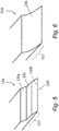
- Figure 5 shows an end portion 122 of a composite strip 110 having a taper 130 in accordance with a further embodiment of the invention.
- the end portion 122 differs from the embodiment of Figure 3 in that the end portion 122 has a stepped taper. More particularly, the end portion has two, spaced apart tapered regions 130a, 130b and a region 131 having little or no taper positioned between the tapered regions 130a, 130b.
- Figure 6 is a detail view of an end portion 222 of a composite strip 210 having a taper 130 in accordance with a yet further embodiment of the invention.
- the end portion 222 differs from the embodiment of Figures 3 and 5 in that the resulting taper 230 has a parabolic profile or curved taper.
- the tapers 130, 230 shown in Figures 5 and 6 can be created by the same method as described above in relation to Figure 3 and using correspondingly-shaped moulding surfaces.
- the taper 30, 130, 230 may have a gradient of 1:100.
- the taper starts at 500mm from the end of the strip and the thickness at the end of the strip is 0mm.
- the taper could have a gradient of between 1:50 and 1:200, and preferably about 1:100.
- the present invention involves providing a composite strip comprising a thermoplastic material and forming an end portion of the strip into a tapered shape using heat and pressure.
- material Prior to heat forming, material may be removed from the end portion of the composite strip. Removing material results in the end portion having a lower volume of composite material per unit length than a main portion of the strip. Consequently, the resulting taper may advantageously have a similar fibre volume fraction as the main portion of the strip.
- the moulding of the taper as described above presents a number of advantages compared to known tapering techniques such as grinding.
- the method may provide a safer and easier way of producing a tapered strip.
- the method may also reduce residual stresses at the surface of the strip which may be caused by machining.
- thermoset matrix materials which is typically used in such strips, because thermoset matrix materials cannot be reshaped by moulding.
- thermoplastic materials become plastic or deformable when heated and then harden when cooled. Heating of the thermoplastic material does not substantially change the chemical properties of the thermoplastic, compared to thermoset materials in which irreversible cross-linking occurs.
- Thermoplastic materials in contrast to thermosets, can also be more readily recycled, hence the strips of the present invention provide the advantage that they may be recycled at the end of their serve life.
- Another advantage of the present invention is that it involves the deformation in only a localised region of the strip. Deforming only a relatively small localized region of the strip requires only minimal heating energy and may be achieved quickly with a minimum of labour and tooling compared to heat forming the whole strip, for example. The tooling can therefore be compact and low in cost.
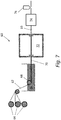
- the composite strip that is to be tapered is formed by a pultrusion process 60 as illustrated in Figure 7 .
- the tapering method as described above may be incorporated into the process 60 for forming the strip 10.
- carbon fibres 62 are pulled from at least one continuous reel 64 in a process direction by a pulling device (not shown).
- the fibres 62 are directed through a supply of molten thermoplastic matrix material 66, by rollers 68 which maintain tension in the fibres 62.
- the matrix-impregnated fibres 70 are then pulled through a die 72 having a cross-sectional profile for forming the material into the final desired cross-sectional shape of the strip 10.
- the strip 10 is then cooled at a cooling station 74 to solidify the matrix material 66 and set the strip 10.
- Cooling of the strip 10 may be performed using any means known in the art.
- the cooling station 74 may comprise a water tank, a cold air stream or a cooling jacket.
- the temperature at which the strip 10 is cooled may be controlled to achieve optimal mechanical properties as known in the art.
- the temperature of the strip 10 may be controlled to achieve optimal properties as it advances through any section of the pultrusion process 60, for example using heaters and/or coolers.
- the pultrusion process 60 produces a continuous strip 10 having a constant cross-sectional profile along its length.
- the strip 10 is cut into discrete portions by a cutting device 76.
- the portions of pultruded material are rolled into reels for subsequent processing such as the tapering method described above.
- the portions of pultruded material are subsequently divided into smaller lengths suitable for use in a spar cap of a wind turbine.
- the cutting may be performed as part of the pultrusion or other strip forming process or may be a subsequent processing step.
- the strips 10 may first be cut into the desired length (e.g. forming a straight edge of the strip) and then subsequently be cut to form the recesses 28 as described above.
- the recesses 28 may be formed in the strips 10 with the dividing cut, for example the cutting means 76 may comprise a die cutter having a zigzag profile.
- the tapering apparatus shown in Figures 4a and 4b may optionally be provided inline with the pultrusion apparatus.
- thermoplastic composite strips made by other methods suitable for forming thermoplastic composite strips, including but not limited to extrusion and lamination.
- thermoplastic matrix material may be applied to the fibres by any means known in the art.
- the fibres are drawn through a bath of liquid matrix material.
- the matrix material may be sprayed onto the fibres or extruded thereon.
- the matrix material of the described embodiment comprises HDPE, other thermoplastic polymers could be used additionally or alternatively without departing from the scope of the invention.
- the matrix material may comprise polypropylene or acrylic e.g. ABS or ASA.
- the thermoplastic matrix material may comprise a polymer that may be a high molecular weight thermoplastic polymer, including but not limited to, polypropylene, polyethylene, nylon, PEI (polyetherimide) and copolymers, more preferably, polypropylene and/or polyethylene.
- thermoplastic polymers for use in the present invention may include, for example, polyolefins, polycarbonates, polyamides, polyether ketones, polyetherimides, polyarylene ketones, liquid crystal polymers, polyarylene sulfides fluoropolymers, polyacetals, polyurethanes, polycarbonates, styrenic polymers, and other thermoplastic polymers known in the art.
- the continuous fibres employed in the present invention may be formed from any conventional fibre material known in the art, such as metal fibres; glass fibres, carbon fibres (e.g. graphite), boron fibres, ceramic fibres (e.g. alumina or silica), aramid fibres, synthetic organic fibres and various other natural or synthetic inorganic or organic fibrous materials known for reinforcing thermoplastic composites. Glass fibres and carbon fibres are particularly desirable for use in the continuous fibres.
- the described embodiments relate to tapering a strip having a substantially rectangular cross-section
- the skilled person would appreciate that the present invention could be applied to composite strips having alternative cross-sectional shapes.
- the strip could have a curved profile or any other alternative shape as known in the art.
- the mould parts would be shaped accordingly.
- the disclosed method allows effective tapering that would have been extremely difficult to achieve by grinding of a curved profile.
- Alternative end profiles may be used to reduce the volume of composite material in the end portion prior to moulding, additionally or alternatively to the described zigzag profile.
- the end may have a sinusoidal, saw toothed, notched or wavy profile or any other regular or irregular geometries that would result in recesses.
- the end may comprise a smaller number of spaced apart notches.
- the notches may be triangular, square or semi-circular, for example.
- recesses described in relation to any of the embodiments above may be formed using other techniques know in the art such as by water jet, laser cutting, ultrasonic knives or a guided saw blade.
- the end portion may be heated by other means known in the art such as infrared heating.
- the end material may be heated to at least 90°C (the glass transition temperature of PP) and/or up to 180°C (the melting temperature of PP).
- a strip may comprise a dividing line through which the strip will subsequently cut. A portion of the strip either side of the dividing line will form end portions of the strip after cutting along the dividing line.
- material may be removed from the portions of the strip and thereafter the strip may be heated and tapered in two directions towards the dividing line. The strip may then subsequently be cut along the cutting line such that the resulting strips already include a taper.
- the 'end portion' to be tapered would be the portion of the strip adjacent the cutting line that would form the end portion of the strip after cutting.
- the side surfaces of the mould may have a varying spacing therebetween.
- the spacing between the side surfaces may be equal to the width of the pultruded strip along the main portion thereof or alternatively may have converging surfaces in order to create a tapered width of the strip.
- the upper or lower mould part could be fixed such that the other of the upper or lower mould part moves relative to the fixed part.
- the mould parts may move relative to each other in any manner such that they exert pressure on the surfaces of the strip to be tapered.
- Figure 4a shows the strip being fed by rollers into the mould
- the strips might be placed in the mould manually or by robotic means.
- the moulding could be integrated into the pultrusion process such that the strip is pulled into position by the pultrusion apparatus as shown in Figure 7 .
- the tapered end portion of the strip desirably has substantially the same fibre volume fraction as the remaining portion of the strip.
- the fibre volume fraction is within 2%, for example within 1% or 0.5%, of the fibre volume fraction of the main portion of the strip.
- a lower fibre volume fraction would result in a lower stiffness, strength and strain to failure of that portion of the strip, which could lead to a large stress concentration locally around the taper. Accordingly, a more even fibre volume fraction will improve the mechanical properties of the strip and resulting component.
- a tapered strip formed in accordance with the invention may be stacked together with a plurality of other tapered strips and bonded together to form a spar cap of a wind turbine blade, for example.
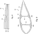
- Figure 8 is a side view showing a plurality of tapered strips 10a-c forming a component 80 such as a spar cap.
- the strips are of generally decreasing lengths from the lowermost strip 10c to the uppermost strip 10a such that the respective ends of the strips are staggered.
- the component 80 therefore generally reduces in thickness towards its end.
- the strips 10a and 10b also have tapered ends 24a, 24b formed according to the methods described above.
- the tapered ends 24a, 24b serve to spread the load path between adjacent strips 10 and avoids abrupt discontinuities between the layers such that stress concentrations that may initiate cracks or delamination are avoided.
- the strips 10a-c may be bonded to each other using an adhesive such as resin.
- a resin infusion process may be used, in which liquid resin is infused between the stacked strips 10a-c to bond the major surfaces of adjacent strips 10a-c in the stack.
- a skin of composite material 100 may optionally be disposed on top of the stack of strips 10a-c to form a smooth surface of the component 80.
- Figure 9 is a cross-sectional view of a wind turbine rotor blade 90 having a plurality of spar caps 80a-d.
- the blade 90 has an outer shell 92, which may be fabricated from two half shells.
- the shell is moulded from glass-fibre reinforced plastic (GRP).
- GRP glass-fibre reinforced plastic
- Parts of the outer shell 92 are of sandwich panel construction and comprise a blade core of lightweight foam (e.g. polyurethane), which is sandwiched between inner and outer GRP layers or 'skins'.
- the blade comprises first and second pairs of spar caps 80a-d arranged between sandwich panel regions of the outer shell 92.
- One spar cap of each pair is integrated with the windward shell and the other spar cap of each pair is integrated with the leeward shell.
- the spar caps 80a-d of the respective pairs are mutually opposed and extend longitudinally along the length of the blade 90.
- a first longitudinally-extending shear web 94 bridges the first pair of spar caps 80a, 80b and a second longitudinally-extending shear web 96 bridges the second pair of spar caps 80c, 80d.
- the shear webs 94, 96 in combination with the spar caps 80a-d form a pair of I-beam structures, which transfer loads effectively from the rotating blade 90 to the hub of the wind turbine (not shown).
- the spar caps 80a-d in particular transfer tensile and compressive bending loads, whilst the shear webs 94, 96 transfer shear stresses in the blade 90.
- Each spar cap 80a-d has a substantially rectangular cross section and is made up of a stack of pultruded strips 10, some or all of which have a tapered end portion as described above in relation to any of the embodiments.
- the number of strips 10 in the stack depends upon the thickness of the strips 10 and the required thickness of the shell, but typically there may be between four and twelve strips 10 in the stack.
Landscapes
- Engineering & Computer Science (AREA)
- Mechanical Engineering (AREA)
- Chemical & Material Sciences (AREA)
- Composite Materials (AREA)
- Moulding By Coating Moulds (AREA)
- Wind Motors (AREA)
Applications Claiming Priority (1)
| Application Number | Priority Date | Filing Date | Title |
|---|---|---|---|
| DKPA201770546 | 2017-07-04 |
Publications (3)
| Publication Number | Publication Date |
|---|---|
| EP3424696A1 true EP3424696A1 (fr) | 2019-01-09 |
| EP3424696C0 EP3424696C0 (fr) | 2023-09-27 |
| EP3424696B1 EP3424696B1 (fr) | 2023-09-27 |
Family
ID=62841981
Family Applications (1)
| Application Number | Title | Priority Date | Filing Date |
|---|---|---|---|
| EP18181174.6A Active EP3424696B1 (fr) | 2017-07-04 | 2018-07-02 | Procédé de rétrécissement d'une bande composite renforcée par des fibres |
Country Status (2)
| Country | Link |
|---|---|
| EP (1) | EP3424696B1 (fr) |
| ES (1) | ES2959366T3 (fr) |
Cited By (5)
| Publication number | Priority date | Publication date | Assignee | Title |
|---|---|---|---|---|
| US20220034293A1 (en) * | 2018-12-10 | 2022-02-03 | Vestas Wind Systems A/S | Improvements relating to wind turbine blade manufacture |
| WO2022073967A1 (fr) * | 2020-10-07 | 2022-04-14 | Lm Wind Power A/S | Bande fibreuse pré-durcie pour une structure porteuse et procédé de fabrication d'une semelle de longeron pour une pale d'éolienne |
| EP4108439A1 (fr) * | 2021-06-25 | 2022-12-28 | LM Wind Power A/S | Capuchon de longeron doté d'une section d'extrémité conique et dentelée |
| WO2025131206A1 (fr) * | 2023-12-20 | 2025-06-26 | Vestas Wind Systems A/S | Capuchon de longeron de pale d'éolienne |
| WO2025131207A1 (fr) * | 2023-12-20 | 2025-06-26 | Vestas Wind Systems A/S | Capuchon de longeron de pale d'éolienne |
Citations (2)
| Publication number | Priority date | Publication date | Assignee | Title |
|---|---|---|---|---|
| WO2011092486A1 (fr) * | 2010-01-28 | 2011-08-04 | Vestas Wind Systems A/S | Amelioration apportees a des techniques de production composites manufacturing |
| US20140154091A1 (en) * | 2008-12-05 | 2014-06-05 | Modular Wind Energy, Inc. | Efficient wind turbine blades, wind turbine blade structures, and associated systems and methods of manufacture, assembly and use |
Family Cites Families (2)
| Publication number | Priority date | Publication date | Assignee | Title |
|---|---|---|---|---|
| GB2482345A (en) * | 2010-07-30 | 2012-02-01 | Vestas Wind Sys As | Tapering an edge of a fibrous reinforcement sheet using a rotary tool |
| WO2014000742A1 (fr) * | 2012-06-25 | 2014-01-03 | Vestas Wind Systems A/S | Procédé et appareil de production d'un bord biseauté sur une tôle contenant un matériau fibreux |
-
2018
- 2018-07-02 EP EP18181174.6A patent/EP3424696B1/fr active Active
- 2018-07-02 ES ES18181174T patent/ES2959366T3/es active Active
Patent Citations (2)
| Publication number | Priority date | Publication date | Assignee | Title |
|---|---|---|---|---|
| US20140154091A1 (en) * | 2008-12-05 | 2014-06-05 | Modular Wind Energy, Inc. | Efficient wind turbine blades, wind turbine blade structures, and associated systems and methods of manufacture, assembly and use |
| WO2011092486A1 (fr) * | 2010-01-28 | 2011-08-04 | Vestas Wind Systems A/S | Amelioration apportees a des techniques de production composites manufacturing |
Cited By (9)
| Publication number | Priority date | Publication date | Assignee | Title |
|---|---|---|---|---|
| US20220034293A1 (en) * | 2018-12-10 | 2022-02-03 | Vestas Wind Systems A/S | Improvements relating to wind turbine blade manufacture |
| US11761422B2 (en) * | 2018-12-10 | 2023-09-19 | Vestas Wind Systems A/S | Relating to wind turbine blade manufacture |
| WO2022073967A1 (fr) * | 2020-10-07 | 2022-04-14 | Lm Wind Power A/S | Bande fibreuse pré-durcie pour une structure porteuse et procédé de fabrication d'une semelle de longeron pour une pale d'éolienne |
| US12466144B2 (en) | 2020-10-07 | 2025-11-11 | Lm Wind Power A/S | Precured fibrous strip for a load-carrying structure for a wind turbine blade |
| EP4108439A1 (fr) * | 2021-06-25 | 2022-12-28 | LM Wind Power A/S | Capuchon de longeron doté d'une section d'extrémité conique et dentelée |
| WO2022269048A1 (fr) * | 2021-06-25 | 2022-12-29 | Lm Wind Power A/S | Protection de longeron pourvue d'une section d'extrémité effilée et dentelée |
| US12540597B2 (en) | 2021-06-25 | 2026-02-03 | Lm Wind Power A/S | Spar cap with tapering and serrated end section |
| WO2025131206A1 (fr) * | 2023-12-20 | 2025-06-26 | Vestas Wind Systems A/S | Capuchon de longeron de pale d'éolienne |
| WO2025131207A1 (fr) * | 2023-12-20 | 2025-06-26 | Vestas Wind Systems A/S | Capuchon de longeron de pale d'éolienne |
Also Published As
| Publication number | Publication date |
|---|---|
| EP3424696C0 (fr) | 2023-09-27 |
| EP3424696B1 (fr) | 2023-09-27 |
| ES2959366T3 (es) | 2024-02-23 |
Similar Documents
| Publication | Publication Date | Title |
|---|---|---|
| EP3424696B1 (fr) | Procédé de rétrécissement d'une bande composite renforcée par des fibres | |
| EP2441571B1 (fr) | Procédé pour la fabrication d'un composant composite en fibres | |
| EP3060385B1 (fr) | Pales d'éolienne | |
| CN1915649B (zh) | 可用于制造转子叶片圆柱盖的一种制造连续层压片的方法 | |
| US9550332B2 (en) | Wing and blade structure using pultruded composites | |
| AU688203B2 (en) | Pultrusion method and apparatus | |
| EP3069017B1 (fr) | Bande de renforcement pour pale d'éolienne | |
| JP7148305B2 (ja) | 航空機の構造的構成要素の強度及び靭性を高めるための方法及び装置 | |
| EP2610165B1 (fr) | Agent de remplissage de gousset composite et procédé de fabrication de cet agent de remplissage de gousset composite | |
| DE69205416T2 (de) | Verfahren zum kontinuierlichen formen von einem faserverstaerkten kunstharzcomposit. | |
| EP0804332B1 (fr) | Dispositif de fabrication d'une barre de renforcement utilisee en construction | |
| US11858225B2 (en) | Pultruded strips | |
| EP2271478B1 (fr) | Préforme composite consolidée | |
| JP6464602B2 (ja) | 積層基材の製造方法、及び積層基材 | |
| EP2815874B1 (fr) | Biseaux décalés pour matrices d'outillage de moulage par compression en continu | |
| CN109311240B (zh) | 用于生产至少部分具有轮廓的纤维增强塑料型材的方法、具有轮廓的纤维增强塑料型材及其用途 | |
| CN114599505B (zh) | 用于由纤维复合材料生产构件的方法 | |
| US12257787B2 (en) | Composite structures | |
| EP3711935A1 (fr) | Procédé et système de fabrication d'un sous-composant pour une pale de rotor d'une éolienne | |
| US12162228B2 (en) | Composite structures | |
| WO2017046577A1 (fr) | Matériau composite | |
| US10786942B2 (en) | Process for the production of a tubular hybrid molding and tubular hybrid molding | |
| EP2580046B1 (fr) | Procédé et dispositif pour la fabrication d'un profilé composite à la section non circulaire | |
| BRPI0716045A2 (pt) | mÉtodo de produÇço para uma peÇa de trabalho composta de material de compàsito de fibra e um componente de compàsito de fibra na forma de um perfil com uma seÇço transversal de perfil que varia sobre o seu comprimento | |
| JPH081801A (ja) | 成形金型 |
Legal Events
| Date | Code | Title | Description |
|---|---|---|---|
| PUAI | Public reference made under article 153(3) epc to a published international application that has entered the european phase |
Free format text: ORIGINAL CODE: 0009012 |
|
| STAA | Information on the status of an ep patent application or granted ep patent |
Free format text: STATUS: THE APPLICATION HAS BEEN PUBLISHED |
|
| AK | Designated contracting states |
Kind code of ref document: A1 Designated state(s): AL AT BE BG CH CY CZ DE DK EE ES FI FR GB GR HR HU IE IS IT LI LT LU LV MC MK MT NL NO PL PT RO RS SE SI SK SM TR |
|
| AX | Request for extension of the european patent |
Extension state: BA ME |
|
| STAA | Information on the status of an ep patent application or granted ep patent |
Free format text: STATUS: REQUEST FOR EXAMINATION WAS MADE |
|
| 17P | Request for examination filed |
Effective date: 20190703 |
|
| RBV | Designated contracting states (corrected) |
Designated state(s): AL AT BE BG CH CY CZ DE DK EE ES FI FR GB GR HR HU IE IS IT LI LT LU LV MC MK MT NL NO PL PT RO RS SE SI SK SM TR |
|
| STAA | Information on the status of an ep patent application or granted ep patent |
Free format text: STATUS: EXAMINATION IS IN PROGRESS |
|
| 17Q | First examination report despatched |
Effective date: 20220222 |
|
| GRAP | Despatch of communication of intention to grant a patent |
Free format text: ORIGINAL CODE: EPIDOSNIGR1 |
|
| STAA | Information on the status of an ep patent application or granted ep patent |
Free format text: STATUS: GRANT OF PATENT IS INTENDED |
|
| INTG | Intention to grant announced |
Effective date: 20230509 |
|
| GRAS | Grant fee paid |
Free format text: ORIGINAL CODE: EPIDOSNIGR3 |
|
| GRAA | (expected) grant |
Free format text: ORIGINAL CODE: 0009210 |
|
| STAA | Information on the status of an ep patent application or granted ep patent |
Free format text: STATUS: THE PATENT HAS BEEN GRANTED |
|
| AK | Designated contracting states |
Kind code of ref document: B1 Designated state(s): AL AT BE BG CH CY CZ DE DK EE ES FI FR GB GR HR HU IE IS IT LI LT LU LV MC MK MT NL NO PL PT RO RS SE SI SK SM TR |
|
| REG | Reference to a national code |
Ref country code: GB Ref legal event code: FG4D |
|
| REG | Reference to a national code |
Ref country code: CH Ref legal event code: EP |
|
| REG | Reference to a national code |
Ref country code: DE Ref legal event code: R096 Ref document number: 602018058158 Country of ref document: DE |
|
| REG | Reference to a national code |
Ref country code: IE Ref legal event code: FG4D |
|
| U01 | Request for unitary effect filed |
Effective date: 20231004 |
|
| U07 | Unitary effect registered |
Designated state(s): AT BE BG DE DK EE FI FR IT LT LU LV MT NL PT SE SI Effective date: 20231013 |
|
| PG25 | Lapsed in a contracting state [announced via postgrant information from national office to epo] |
Ref country code: GR Free format text: LAPSE BECAUSE OF FAILURE TO SUBMIT A TRANSLATION OF THE DESCRIPTION OR TO PAY THE FEE WITHIN THE PRESCRIBED TIME-LIMIT Effective date: 20231228 |
|
| PG25 | Lapsed in a contracting state [announced via postgrant information from national office to epo] |
Ref country code: RS Free format text: LAPSE BECAUSE OF FAILURE TO SUBMIT A TRANSLATION OF THE DESCRIPTION OR TO PAY THE FEE WITHIN THE PRESCRIBED TIME-LIMIT Effective date: 20230927 Ref country code: NO Free format text: LAPSE BECAUSE OF FAILURE TO SUBMIT A TRANSLATION OF THE DESCRIPTION OR TO PAY THE FEE WITHIN THE PRESCRIBED TIME-LIMIT Effective date: 20231227 Ref country code: HR Free format text: LAPSE BECAUSE OF FAILURE TO SUBMIT A TRANSLATION OF THE DESCRIPTION OR TO PAY THE FEE WITHIN THE PRESCRIBED TIME-LIMIT Effective date: 20230927 Ref country code: GR Free format text: LAPSE BECAUSE OF FAILURE TO SUBMIT A TRANSLATION OF THE DESCRIPTION OR TO PAY THE FEE WITHIN THE PRESCRIBED TIME-LIMIT Effective date: 20231228 |
|
| REG | Reference to a national code |
Ref country code: ES Ref legal event code: FG2A Ref document number: 2959366 Country of ref document: ES Kind code of ref document: T3 Effective date: 20240223 |
|
| PG25 | Lapsed in a contracting state [announced via postgrant information from national office to epo] |
Ref country code: IS Free format text: LAPSE BECAUSE OF FAILURE TO SUBMIT A TRANSLATION OF THE DESCRIPTION OR TO PAY THE FEE WITHIN THE PRESCRIBED TIME-LIMIT Effective date: 20240127 |
|
| PG25 | Lapsed in a contracting state [announced via postgrant information from national office to epo] |
Ref country code: SM Free format text: LAPSE BECAUSE OF FAILURE TO SUBMIT A TRANSLATION OF THE DESCRIPTION OR TO PAY THE FEE WITHIN THE PRESCRIBED TIME-LIMIT Effective date: 20230927 Ref country code: RO Free format text: LAPSE BECAUSE OF FAILURE TO SUBMIT A TRANSLATION OF THE DESCRIPTION OR TO PAY THE FEE WITHIN THE PRESCRIBED TIME-LIMIT Effective date: 20230927 Ref country code: IS Free format text: LAPSE BECAUSE OF FAILURE TO SUBMIT A TRANSLATION OF THE DESCRIPTION OR TO PAY THE FEE WITHIN THE PRESCRIBED TIME-LIMIT Effective date: 20240127 Ref country code: CZ Free format text: LAPSE BECAUSE OF FAILURE TO SUBMIT A TRANSLATION OF THE DESCRIPTION OR TO PAY THE FEE WITHIN THE PRESCRIBED TIME-LIMIT Effective date: 20230927 Ref country code: SK Free format text: LAPSE BECAUSE OF FAILURE TO SUBMIT A TRANSLATION OF THE DESCRIPTION OR TO PAY THE FEE WITHIN THE PRESCRIBED TIME-LIMIT Effective date: 20230927 |
|
| PG25 | Lapsed in a contracting state [announced via postgrant information from national office to epo] |
Ref country code: PL Free format text: LAPSE BECAUSE OF FAILURE TO SUBMIT A TRANSLATION OF THE DESCRIPTION OR TO PAY THE FEE WITHIN THE PRESCRIBED TIME-LIMIT Effective date: 20230927 |
|
| REG | Reference to a national code |
Ref country code: DE Ref legal event code: R097 Ref document number: 602018058158 Country of ref document: DE |
|
| PLBE | No opposition filed within time limit |
Free format text: ORIGINAL CODE: 0009261 |
|
| STAA | Information on the status of an ep patent application or granted ep patent |
Free format text: STATUS: NO OPPOSITION FILED WITHIN TIME LIMIT |
|
| U20 | Renewal fee for the european patent with unitary effect paid |
Year of fee payment: 7 Effective date: 20240725 |
|
| 26N | No opposition filed |
Effective date: 20240628 |
|
| PG25 | Lapsed in a contracting state [announced via postgrant information from national office to epo] |
Ref country code: MC Free format text: LAPSE BECAUSE OF FAILURE TO SUBMIT A TRANSLATION OF THE DESCRIPTION OR TO PAY THE FEE WITHIN THE PRESCRIBED TIME-LIMIT Effective date: 20230927 |
|
| REG | Reference to a national code |
Ref country code: CH Ref legal event code: PL |
|
| PG25 | Lapsed in a contracting state [announced via postgrant information from national office to epo] |
Ref country code: CH Free format text: LAPSE BECAUSE OF NON-PAYMENT OF DUE FEES Effective date: 20240731 |
|
| PG25 | Lapsed in a contracting state [announced via postgrant information from national office to epo] |
Ref country code: IE Free format text: LAPSE BECAUSE OF NON-PAYMENT OF DUE FEES Effective date: 20240702 |
|
| U20 | Renewal fee for the european patent with unitary effect paid |
Year of fee payment: 8 Effective date: 20250725 |
|
| PGFP | Annual fee paid to national office [announced via postgrant information from national office to epo] |
Ref country code: ES Payment date: 20250812 Year of fee payment: 8 |
|
| PGFP | Annual fee paid to national office [announced via postgrant information from national office to epo] |
Ref country code: GB Payment date: 20250722 Year of fee payment: 8 |
|
| PG25 | Lapsed in a contracting state [announced via postgrant information from national office to epo] |
Ref country code: CY Free format text: LAPSE BECAUSE OF FAILURE TO SUBMIT A TRANSLATION OF THE DESCRIPTION OR TO PAY THE FEE WITHIN THE PRESCRIBED TIME-LIMIT; INVALID AB INITIO Effective date: 20180702 |
|
| PG25 | Lapsed in a contracting state [announced via postgrant information from national office to epo] |
Ref country code: HU Free format text: LAPSE BECAUSE OF FAILURE TO SUBMIT A TRANSLATION OF THE DESCRIPTION OR TO PAY THE FEE WITHIN THE PRESCRIBED TIME-LIMIT; INVALID AB INITIO Effective date: 20180702 |