EP3424708B1 - Fabrication additive avec une gaine renforcée de fibres - Google Patents
Fabrication additive avec une gaine renforcée de fibres Download PDFInfo
- Publication number
- EP3424708B1 EP3424708B1 EP18168731.0A EP18168731A EP3424708B1 EP 3424708 B1 EP3424708 B1 EP 3424708B1 EP 18168731 A EP18168731 A EP 18168731A EP 3424708 B1 EP3424708 B1 EP 3424708B1
- Authority
- EP
- European Patent Office
- Prior art keywords
- feedstock line
- resin
- uncured state
- rigid uncured
- rigid
- Prior art date
- Legal status (The legal status is an assumption and is not a legal conclusion. Google has not performed a legal analysis and makes no representation as to the accuracy of the status listed.)
- Not-in-force
Links
Images


Classifications
-
- B—PERFORMING OPERATIONS; TRANSPORTING
- B33—ADDITIVE MANUFACTURING TECHNOLOGY
- B33Y—ADDITIVE MANUFACTURING, i.e. MANUFACTURING OF THREE-DIMENSIONAL [3D] OBJECTS BY ADDITIVE DEPOSITION, ADDITIVE AGGLOMERATION OR ADDITIVE LAYERING, e.g. BY 3D PRINTING, STEREOLITHOGRAPHY OR SELECTIVE LASER SINTERING
- B33Y70/00—Materials specially adapted for additive manufacturing
- B33Y70/10—Composites of different types of material, e.g. mixtures of ceramics and polymers or mixtures of metals and biomaterials
-
- B—PERFORMING OPERATIONS; TRANSPORTING
- B29—WORKING OF PLASTICS; WORKING OF SUBSTANCES IN A PLASTIC STATE IN GENERAL
- B29C—SHAPING OR JOINING OF PLASTICS; SHAPING OF MATERIAL IN A PLASTIC STATE, NOT OTHERWISE PROVIDED FOR; AFTER-TREATMENT OF THE SHAPED PRODUCTS, e.g. REPAIRING
- B29C64/00—Additive manufacturing, i.e. manufacturing of three-dimensional [3D] objects by additive deposition, additive agglomeration or additive layering, e.g. by 3D printing, stereolithography or selective laser sintering
- B29C64/10—Processes of additive manufacturing
- B29C64/106—Processes of additive manufacturing using only liquids or viscous materials, e.g. depositing a continuous bead of viscous material
- B29C64/118—Processes of additive manufacturing using only liquids or viscous materials, e.g. depositing a continuous bead of viscous material using filamentary material being melted, e.g. fused deposition modelling [FDM]
-
- B—PERFORMING OPERATIONS; TRANSPORTING
- B29—WORKING OF PLASTICS; WORKING OF SUBSTANCES IN A PLASTIC STATE IN GENERAL
- B29C—SHAPING OR JOINING OF PLASTICS; SHAPING OF MATERIAL IN A PLASTIC STATE, NOT OTHERWISE PROVIDED FOR; AFTER-TREATMENT OF THE SHAPED PRODUCTS, e.g. REPAIRING
- B29C64/00—Additive manufacturing, i.e. manufacturing of three-dimensional [3D] objects by additive deposition, additive agglomeration or additive layering, e.g. by 3D printing, stereolithography or selective laser sintering
- B29C64/30—Auxiliary operations or equipment
- B29C64/307—Handling of material to be used in additive manufacturing
- B29C64/314—Preparation
-
- B—PERFORMING OPERATIONS; TRANSPORTING
- B29—WORKING OF PLASTICS; WORKING OF SUBSTANCES IN A PLASTIC STATE IN GENERAL
- B29C—SHAPING OR JOINING OF PLASTICS; SHAPING OF MATERIAL IN A PLASTIC STATE, NOT OTHERWISE PROVIDED FOR; AFTER-TREATMENT OF THE SHAPED PRODUCTS, e.g. REPAIRING
- B29C64/00—Additive manufacturing, i.e. manufacturing of three-dimensional [3D] objects by additive deposition, additive agglomeration or additive layering, e.g. by 3D printing, stereolithography or selective laser sintering
- B29C64/10—Processes of additive manufacturing
- B29C64/141—Processes of additive manufacturing using only solid materials
- B29C64/147—Processes of additive manufacturing using only solid materials using sheet material, e.g. laminated object manufacturing [LOM] or laminating sheet material precut to local cross sections of the 3D object
-
- B—PERFORMING OPERATIONS; TRANSPORTING
- B29—WORKING OF PLASTICS; WORKING OF SUBSTANCES IN A PLASTIC STATE IN GENERAL
- B29C—SHAPING OR JOINING OF PLASTICS; SHAPING OF MATERIAL IN A PLASTIC STATE, NOT OTHERWISE PROVIDED FOR; AFTER-TREATMENT OF THE SHAPED PRODUCTS, e.g. REPAIRING
- B29C64/00—Additive manufacturing, i.e. manufacturing of three-dimensional [3D] objects by additive deposition, additive agglomeration or additive layering, e.g. by 3D printing, stereolithography or selective laser sintering
- B29C64/10—Processes of additive manufacturing
- B29C64/165—Processes of additive manufacturing using a combination of solid and fluid materials, e.g. a powder selectively bound by a liquid binder, catalyst, inhibitor or energy absorber
-
- B—PERFORMING OPERATIONS; TRANSPORTING
- B29—WORKING OF PLASTICS; WORKING OF SUBSTANCES IN A PLASTIC STATE IN GENERAL
- B29C—SHAPING OR JOINING OF PLASTICS; SHAPING OF MATERIAL IN A PLASTIC STATE, NOT OTHERWISE PROVIDED FOR; AFTER-TREATMENT OF THE SHAPED PRODUCTS, e.g. REPAIRING
- B29C64/00—Additive manufacturing, i.e. manufacturing of three-dimensional [3D] objects by additive deposition, additive agglomeration or additive layering, e.g. by 3D printing, stereolithography or selective laser sintering
- B29C64/20—Apparatus for additive manufacturing; Details thereof or accessories therefor
- B29C64/205—Means for applying layers
- B29C64/209—Heads; Nozzles
-
- B—PERFORMING OPERATIONS; TRANSPORTING
- B29—WORKING OF PLASTICS; WORKING OF SUBSTANCES IN A PLASTIC STATE IN GENERAL
- B29C—SHAPING OR JOINING OF PLASTICS; SHAPING OF MATERIAL IN A PLASTIC STATE, NOT OTHERWISE PROVIDED FOR; AFTER-TREATMENT OF THE SHAPED PRODUCTS, e.g. REPAIRING
- B29C64/00—Additive manufacturing, i.e. manufacturing of three-dimensional [3D] objects by additive deposition, additive agglomeration or additive layering, e.g. by 3D printing, stereolithography or selective laser sintering
- B29C64/20—Apparatus for additive manufacturing; Details thereof or accessories therefor
- B29C64/295—Heating elements
-
- B—PERFORMING OPERATIONS; TRANSPORTING
- B29—WORKING OF PLASTICS; WORKING OF SUBSTANCES IN A PLASTIC STATE IN GENERAL
- B29C—SHAPING OR JOINING OF PLASTICS; SHAPING OF MATERIAL IN A PLASTIC STATE, NOT OTHERWISE PROVIDED FOR; AFTER-TREATMENT OF THE SHAPED PRODUCTS, e.g. REPAIRING
- B29C64/00—Additive manufacturing, i.e. manufacturing of three-dimensional [3D] objects by additive deposition, additive agglomeration or additive layering, e.g. by 3D printing, stereolithography or selective laser sintering
- B29C64/30—Auxiliary operations or equipment
- B29C64/307—Handling of material to be used in additive manufacturing
- B29C64/321—Feeding
- B29C64/336—Feeding of two or more materials
-
- B—PERFORMING OPERATIONS; TRANSPORTING
- B29—WORKING OF PLASTICS; WORKING OF SUBSTANCES IN A PLASTIC STATE IN GENERAL
- B29C—SHAPING OR JOINING OF PLASTICS; SHAPING OF MATERIAL IN A PLASTIC STATE, NOT OTHERWISE PROVIDED FOR; AFTER-TREATMENT OF THE SHAPED PRODUCTS, e.g. REPAIRING
- B29C64/00—Additive manufacturing, i.e. manufacturing of three-dimensional [3D] objects by additive deposition, additive agglomeration or additive layering, e.g. by 3D printing, stereolithography or selective laser sintering
- B29C64/30—Auxiliary operations or equipment
- B29C64/386—Data acquisition or data processing for additive manufacturing
- B29C64/393—Data acquisition or data processing for additive manufacturing for controlling or regulating additive manufacturing processes
-
- B—PERFORMING OPERATIONS; TRANSPORTING
- B29—WORKING OF PLASTICS; WORKING OF SUBSTANCES IN A PLASTIC STATE IN GENERAL
- B29C—SHAPING OR JOINING OF PLASTICS; SHAPING OF MATERIAL IN A PLASTIC STATE, NOT OTHERWISE PROVIDED FOR; AFTER-TREATMENT OF THE SHAPED PRODUCTS, e.g. REPAIRING
- B29C70/00—Shaping composites, i.e. plastics material comprising reinforcements, fillers or preformed parts, e.g. inserts
- B29C70/04—Shaping composites, i.e. plastics material comprising reinforcements, fillers or preformed parts, e.g. inserts comprising reinforcements only, e.g. self-reinforcing plastics
- B29C70/06—Fibrous reinforcements only
- B29C70/10—Fibrous reinforcements only characterised by the structure of fibrous reinforcements, e.g. hollow fibres
- B29C70/16—Fibrous reinforcements only characterised by the structure of fibrous reinforcements, e.g. hollow fibres using fibres of substantial or continuous length
- B29C70/20—Fibrous reinforcements only characterised by the structure of fibrous reinforcements, e.g. hollow fibres using fibres of substantial or continuous length oriented in a single direction, e.g. roofing or other parallel fibres
- B29C70/205—Fibrous reinforcements only characterised by the structure of fibrous reinforcements, e.g. hollow fibres using fibres of substantial or continuous length oriented in a single direction, e.g. roofing or other parallel fibres the structure being shaped to form a three-dimensional configuration
-
- B—PERFORMING OPERATIONS; TRANSPORTING
- B29—WORKING OF PLASTICS; WORKING OF SUBSTANCES IN A PLASTIC STATE IN GENERAL
- B29C—SHAPING OR JOINING OF PLASTICS; SHAPING OF MATERIAL IN A PLASTIC STATE, NOT OTHERWISE PROVIDED FOR; AFTER-TREATMENT OF THE SHAPED PRODUCTS, e.g. REPAIRING
- B29C70/00—Shaping composites, i.e. plastics material comprising reinforcements, fillers or preformed parts, e.g. inserts
- B29C70/04—Shaping composites, i.e. plastics material comprising reinforcements, fillers or preformed parts, e.g. inserts comprising reinforcements only, e.g. self-reinforcing plastics
- B29C70/06—Fibrous reinforcements only
- B29C70/10—Fibrous reinforcements only characterised by the structure of fibrous reinforcements, e.g. hollow fibres
- B29C70/16—Fibrous reinforcements only characterised by the structure of fibrous reinforcements, e.g. hollow fibres using fibres of substantial or continuous length
- B29C70/24—Fibrous reinforcements only characterised by the structure of fibrous reinforcements, e.g. hollow fibres using fibres of substantial or continuous length oriented in at least three directions forming a three-dimensional [3D] structure
-
- B—PERFORMING OPERATIONS; TRANSPORTING
- B29—WORKING OF PLASTICS; WORKING OF SUBSTANCES IN A PLASTIC STATE IN GENERAL
- B29C—SHAPING OR JOINING OF PLASTICS; SHAPING OF MATERIAL IN A PLASTIC STATE, NOT OTHERWISE PROVIDED FOR; AFTER-TREATMENT OF THE SHAPED PRODUCTS, e.g. REPAIRING
- B29C70/00—Shaping composites, i.e. plastics material comprising reinforcements, fillers or preformed parts, e.g. inserts
- B29C70/04—Shaping composites, i.e. plastics material comprising reinforcements, fillers or preformed parts, e.g. inserts comprising reinforcements only, e.g. self-reinforcing plastics
- B29C70/28—Shaping operations therefor
- B29C70/30—Shaping by lay-up, i.e. applying fibres, tape or broadsheet on a mould, former or core; Shaping by spray-up, i.e. spraying of fibres on a mould, former or core
- B29C70/38—Automated lay-up, e.g. using robots, laying filaments according to predetermined patterns
- B29C70/382—Automated fiber placement [AFP]
-
- B—PERFORMING OPERATIONS; TRANSPORTING
- B33—ADDITIVE MANUFACTURING TECHNOLOGY
- B33Y—ADDITIVE MANUFACTURING, i.e. MANUFACTURING OF THREE-DIMENSIONAL [3D] OBJECTS BY ADDITIVE DEPOSITION, ADDITIVE AGGLOMERATION OR ADDITIVE LAYERING, e.g. BY 3D PRINTING, STEREOLITHOGRAPHY OR SELECTIVE LASER SINTERING
- B33Y10/00—Processes of additive manufacturing
-
- B—PERFORMING OPERATIONS; TRANSPORTING
- B33—ADDITIVE MANUFACTURING TECHNOLOGY
- B33Y—ADDITIVE MANUFACTURING, i.e. MANUFACTURING OF THREE-DIMENSIONAL [3D] OBJECTS BY ADDITIVE DEPOSITION, ADDITIVE AGGLOMERATION OR ADDITIVE LAYERING, e.g. BY 3D PRINTING, STEREOLITHOGRAPHY OR SELECTIVE LASER SINTERING
- B33Y30/00—Apparatus for additive manufacturing; Details thereof or accessories therefor
-
- B—PERFORMING OPERATIONS; TRANSPORTING
- B33—ADDITIVE MANUFACTURING TECHNOLOGY
- B33Y—ADDITIVE MANUFACTURING, i.e. MANUFACTURING OF THREE-DIMENSIONAL [3D] OBJECTS BY ADDITIVE DEPOSITION, ADDITIVE AGGLOMERATION OR ADDITIVE LAYERING, e.g. BY 3D PRINTING, STEREOLITHOGRAPHY OR SELECTIVE LASER SINTERING
- B33Y40/00—Auxiliary operations or equipment, e.g. for material handling
-
- B—PERFORMING OPERATIONS; TRANSPORTING
- B33—ADDITIVE MANUFACTURING TECHNOLOGY
- B33Y—ADDITIVE MANUFACTURING, i.e. MANUFACTURING OF THREE-DIMENSIONAL [3D] OBJECTS BY ADDITIVE DEPOSITION, ADDITIVE AGGLOMERATION OR ADDITIVE LAYERING, e.g. BY 3D PRINTING, STEREOLITHOGRAPHY OR SELECTIVE LASER SINTERING
- B33Y50/00—Data acquisition or data processing for additive manufacturing
- B33Y50/02—Data acquisition or data processing for additive manufacturing for controlling or regulating additive manufacturing processes
-
- B—PERFORMING OPERATIONS; TRANSPORTING
- B29—WORKING OF PLASTICS; WORKING OF SUBSTANCES IN A PLASTIC STATE IN GENERAL
- B29C—SHAPING OR JOINING OF PLASTICS; SHAPING OF MATERIAL IN A PLASTIC STATE, NOT OTHERWISE PROVIDED FOR; AFTER-TREATMENT OF THE SHAPED PRODUCTS, e.g. REPAIRING
- B29C64/00—Additive manufacturing, i.e. manufacturing of three-dimensional [3D] objects by additive deposition, additive agglomeration or additive layering, e.g. by 3D printing, stereolithography or selective laser sintering
- B29C64/10—Processes of additive manufacturing
- B29C64/106—Processes of additive manufacturing using only liquids or viscous materials, e.g. depositing a continuous bead of viscous material
-
- B—PERFORMING OPERATIONS; TRANSPORTING
- B29—WORKING OF PLASTICS; WORKING OF SUBSTANCES IN A PLASTIC STATE IN GENERAL
- B29C—SHAPING OR JOINING OF PLASTICS; SHAPING OF MATERIAL IN A PLASTIC STATE, NOT OTHERWISE PROVIDED FOR; AFTER-TREATMENT OF THE SHAPED PRODUCTS, e.g. REPAIRING
- B29C70/00—Shaping composites, i.e. plastics material comprising reinforcements, fillers or preformed parts, e.g. inserts
- B29C70/04—Shaping composites, i.e. plastics material comprising reinforcements, fillers or preformed parts, e.g. inserts comprising reinforcements only, e.g. self-reinforcing plastics
- B29C70/28—Shaping operations therefor
- B29C70/30—Shaping by lay-up, i.e. applying fibres, tape or broadsheet on a mould, former or core; Shaping by spray-up, i.e. spraying of fibres on a mould, former or core
- B29C70/38—Automated lay-up, e.g. using robots, laying filaments according to predetermined patterns
- B29C70/386—Automated tape laying [ATL]
-
- B—PERFORMING OPERATIONS; TRANSPORTING
- B29—WORKING OF PLASTICS; WORKING OF SUBSTANCES IN A PLASTIC STATE IN GENERAL
- B29K—INDEXING SCHEME ASSOCIATED WITH SUBCLASSES B29B, B29C OR B29D, RELATING TO MOULDING MATERIALS OR TO MATERIALS FOR MOULDS, REINFORCEMENTS, FILLERS OR PREFORMED PARTS, e.g. INSERTS
- B29K2105/00—Condition, form or state of moulded material or of the material to be shaped
- B29K2105/06—Condition, form or state of moulded material or of the material to be shaped containing reinforcements, fillers or inserts
- B29K2105/08—Condition, form or state of moulded material or of the material to be shaped containing reinforcements, fillers or inserts of continuous length, e.g. cords, rovings, mats, fabrics, strands or yarns
-
- B—PERFORMING OPERATIONS; TRANSPORTING
- B29—WORKING OF PLASTICS; WORKING OF SUBSTANCES IN A PLASTIC STATE IN GENERAL
- B29K—INDEXING SCHEME ASSOCIATED WITH SUBCLASSES B29B, B29C OR B29D, RELATING TO MOULDING MATERIALS OR TO MATERIALS FOR MOULDS, REINFORCEMENTS, FILLERS OR PREFORMED PARTS, e.g. INSERTS
- B29K2995/00—Properties of moulding materials, reinforcements, fillers, preformed parts or moulds
- B29K2995/0037—Other properties
- B29K2995/0078—Shear strength
-
- B—PERFORMING OPERATIONS; TRANSPORTING
- B29—WORKING OF PLASTICS; WORKING OF SUBSTANCES IN A PLASTIC STATE IN GENERAL
- B29L—INDEXING SCHEME ASSOCIATED WITH SUBCLASS B29C, RELATING TO PARTICULAR ARTICLES
- B29L2031/00—Other particular articles
- B29L2031/30—Vehicles, e.g. ships or aircraft, or body parts thereof
- B29L2031/3076—Aircrafts
Definitions
- the present disclosure relates to additive manufacturing.
- An additive manufacturing process may include dispensing or extruding a feedstock material from a print head, or nozzle, that is capable of moving in three dimensions under computer control to manufacture a part.
- a feedstock material from a print head, or nozzle
- its advancement through the print head may be difficult or result in undesirable effects.
- the feedstock material is or includes a glutinous material
- the feedstock material may gum-up, clog, or otherwise foul the print head.
- the fibers may kink, break, or otherwise buckle and become damaged or clog the print head.
- the resin may undesirably gradually cure inside the print head to progressively clog the print head and partially or completely obstruct the operative advancement of the feedstock material through the print head.
- Document EP 3 124 213 A1 relates to a system for additively manufacturing a composite part, the system comprising a delivery guide, movable relative to a surface.
- the delivery guide is configured to deposit at least a segment of a continuous flexible line along a print path.
- the continuous flexible line comprises a non-resin component and a thermosetting-resin component.
- the thermosetting-resin component comprises a first part and a second part.
- the system further comprises a first resin-part applicator, configured to apply a first quantity of the first part to the non-resin component, and a second resin-part applicator, configured to apply a second quantity of the second part to the first quantity of the first part of a thermosetting resin, applied to the non-resin component.
- the system also comprises a feed mechanism, configured to pull the non-resin component through the first resin-part applicator and the second resin-part applicator, and to push the continuous flexible line out of the delivery guide.
- the system comprises a fiber supply, a resin supply, a rigidizing mechanism, a delivery guide, a feed mechanism, a de-rigidizing mechanism, and a curing mechanism.
- the fiber supply is configured to dispense the elongate fibers.
- the resin supply is configured to apply a resin to the elongate fibers, dispensed from the fiber supply, to create a feedstock line.
- the feedstock line comprises the elongate fibers, at least partially encapsulated in the resin, which is in a first non-rigid uncured state.
- the rigidizing mechanism is to receive the feedstock line with the resin in the first non-rigid uncured state.
- the rigidizing mechanism is configured to transform the resin of the feedstock line from the first non-rigid uncured state to a rigid uncured state.
- the feedstock line and the resin are more rigid when the resin is in the rigid uncured state than when the resin is in the first non-rigid uncured state.
- the delivery guide is to receive the feedstock line from the rigidizing mechanism with the resin in the rigid uncured state.
- the delivery guide is configured to deposit the feedstock line along a print path.
- the feed mechanism is configured to feed the feedstock line through the delivery guide.
- the de-rigidizing mechanism is configured to transform the resin of the feedstock line, as the feedstock line passes through the delivery guide or as the feedstock line exits the delivery guide, from the rigid uncured state to a second non-rigid uncured state, so that, before the feedstock line is deposited along the print path by the delivery guide, the resin of the feedstock line, exiting the delivery guide, is in the second non-rigid uncured state.
- the feedstock line and the resin are less rigid when the resin is in the second non-rigid uncured state than when the resin is in the rigid uncured state.
- the curing mechanism is configured to transform the resin of the feedstock line, deposited by the delivery guide along the print path, from the second non-rigid uncured state to an at least partially cured state.
- the system therefore may be used to manufacture the object from a fiber reinforced composite material that is created from the resin and the elongate fibers while the object is being manufactured. Moreover, the system may be used to manufacture the object with the elongate fibers being oriented in desired and/or predetermined orientations throughout the object, such as to define desired properties of the object.
- the resin is uncured when applied to the elongate fibers to create the feedstock line
- the first non-rigid uncured state of the feedstock line comprises the resin in a viscous condition.
- the resin of the feedstock line would be difficult to handle by the system, and the feed mechanism and the delivery guide thereof, for example, gumming up or otherwise soiling component parts of the system. Moreover, if the resin were in such a viscous state, the elongate fibers may be caused to buckle at the inlet to or within the delivery guide. Accordingly, the rigidizing mechanism transforms the feedstock line from the first non-rigid uncured state to the rigid uncured state so that the feed mechanism can advance the feedstock line into the delivery guide without soiling or damaging the feed mechanism, and without the elongate fibers buckling, breaking, or otherwise becoming damaged.
- the feedstock line is then in the rigid uncured state, it will easily be advanced through the delivery guide for ultimate depositing along the print path to manufacture the object.
- the feedstock line in its rigid uncured state is too rigid for deposition along the print path in three-dimensions. Accordingly, the de-rigidizing mechanism is provided to transform the feedstock line from the rigid uncured state to a sufficiently non-rigid uncured state-the second non-rigid uncured state-for ultimate deposition along the print path.
- the de-rigidizing mechanism may de-rigidize the feedstock line either as it is passing through the delivery guide or as the feedstock line exits the delivery guide, depending on the configuration of the de-rigidizing mechanism and depending on the properties of the feedstock line in the second non-rigid uncured state.
- the curing mechanism transforms the resin from the second non-rigid uncured state to the at least partially cured state, to at least partially cure the object while it is being manufactured, or in situ.
- the method comprises applying a resin in a first non-rigid uncured state to elongate fibers to create a feedstock line.
- the feedstock line comprises the elongate fibers at least partially encapsulated in the resin.
- the method also comprises transforming the resin of the feedstock line from the first non-rigid uncured state to a rigid uncured state.
- the feedstock line and the resin are more rigid when the resin is in the rigid uncured state than when the resin is in the first non-rigid uncured state.
- the method further comprises introducing the feedstock line into a delivery guide with the resin of the feedstock line in the rigid uncured state.
- the method additionally comprises transforming the resin of the feedstock line from the rigid uncured state to a second non-rigid uncured state as the feedstock line passes through the delivery guide or as the feedstock line exits the delivery guide.
- the feedstock line and the resin are less rigid when the resin is in the second non-rigid uncured state than when the resin is in the rigid uncured state.
- the method also comprises depositing the feedstock line along a print path, with the resin of the feedstock line in the second non-rigid uncured state, using the delivery guide.
- the method further comprises at least partially curing the resin of the feedstock line after the feedstock line is deposited by the delivery guide along the print path.
- the method therefore may implemented to manufacture the object from a fiber reinforced composite material that is created from the resin and the elongate fibers while the object is being manufactured. Moreover, the method may be implemented to manufacture the object with the elongate fibers being oriented in desired and/or predetermined orientations throughout the object, such as to define desired properties of the object.
- the resin is uncured when applied to the elongate fibers to create the feedstock line
- the first non-rigid uncured state of the feedstock line comprises the resin in a viscous condition.
- the resin of the feedstock line would be difficult to introduce into the delivery guide, for example, potentially gumming up the delivery guide or buckling, kinking, or even breaking the elongate fibers. Accordingly, transforming the resin to the rigid uncured state facilitates the introduction of the feedstock line into and the passage of the feedstock line through the delivery guide, without the elongate fibers buckling, breaking, or otherwise becoming damaged, and without the resin soiling an associated system.
- Fig. 1 solid lines, if any, connecting various elements and/or components may represent mechanical, electrical, fluid, optical, electromagnetic and other couplings and/or combinations thereof.
- "coupled” means associated directly as well as indirectly.
- a member A may be directly associated with a member B, or may be indirectly associated therewith, e.g., via another member C. It will be understood that not all relationships among the various disclosed elements are necessarily represented. Accordingly, couplings other than those depicted in the block diagrams may also exist.
- Dashed lines, if any, connecting blocks designating the various elements and/or components represent couplings similar in function and purpose to those represented by solid lines; however, couplings represented by the dashed lines may either be selectively provided or may relate to alternative examples of the present disclosure.
- elements and/or components, if any, represented with dashed lines indicate alternative examples of the present disclosure.
- One or more elements shown in solid and/or dashed lines may be omitted from a particular example without departing from the scope of the present disclosure.
- Environmental elements, if any, are represented with dotted lines. Virtual (imaginary) elements may also be shown for clarity.
- the blocks may represent operations and/or portions thereof and lines connecting the various blocks do not imply any particular order or dependency of the operations or portions thereof. Blocks represented by dashed lines indicate alternative operations and/or portions thereof. Dashed lines, if any, connecting the various blocks represent alternative dependencies of the operations or portions thereof. It will be understood that not all dependencies among the various disclosed operations are necessarily represented. Figs. 3 and 4 and the accompanying disclosure describing the operations of the method(s) set forth herein should not be interpreted as necessarily determining a sequence in which the operations are to be performed. Rather, although one illustrative order is indicated, it is to be understood that the sequence of the operations may be modified when appropriate. Accordingly, certain operations may be performed in a different order or simultaneously. Additionally, those skilled in the art will appreciate that not all operations described need be performed.
- first, second, etc. are used herein merely as labels, and are not intended to impose ordinal, positional, or hierarchical requirements on the items to which these terms refer. Moreover, reference to, e.g., a “second” item does not require or preclude the existence of, e.g., a "first” or lower-numbered item, and/or, e.g., a "third" or higher-numbered item.
- a system, apparatus, structure, article, element, component, or hardware “configured to” perform a specified function is indeed capable of performing the specified function without any alteration, rather than merely having potential to perform the specified function after further modification.
- the system, apparatus, structure, article, element, component, or hardware “configured to” perform a specified function is specifically selected, created, implemented, utilized, programmed, and/or designed for the purpose of performing the specified function.
- "configured to” denotes existing characteristics of a system, apparatus, structure, article, element, component, or hardware which enable the system, apparatus, structure, article, element, component, or hardware to perform the specified function without further modification.
- a system, apparatus, structure, article, element, component, or hardware described as being “configured to” perform a particular function may additionally or alternatively be described as being “adapted to” and/or as being “operative to” perform that function.
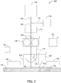
- System 100 for additively manufacturing object 102 is disclosed.
- System 100 comprises fiber supply 122, resin supply 124, rigidizing mechanism 112, delivery guide 116, feed mechanism 126, de-rigidizing mechanism 118, and curing mechanism 120.
- Fiber supply 122 is configured to dispense elongate fibers 108.
- Resin supply 124 is configured to apply resin 110 to elongate fibers 108, dispensed from fiber supply 122, to create feedstock line 106.
- Feedstock line 106 comprises elongate fibers 108, at least partially encapsulated in resin 110, which is in a first non-rigid uncured state.
- Rigidizing mechanism 112 is to receive feedstock line 106 with resin 110 in the first non-rigid uncured state. Rigidizing mechanism 112 is configured to transform resin 110 of feedstock line 106 from the first non-rigid uncured state to a rigid uncured state. Feedstock line 106 and resin 110 are more rigid when resin 110 is in the rigid uncured state than when resin 110 is in the first non-rigid uncured state. Delivery guide 116 is to receive feedstock line 106 from rigidizing mechanism 112 with resin 110 in the rigid uncured state. Delivery guide 116 is configured to deposit feedstock line 106 along print path 114. Feed mechanism 126 is configured to feed feedstock line 106 through delivery guide 116.
- De-rigidizing mechanism 118 is configured to transform resin 110 of feedstock line 106, as feedstock line 106 passes through delivery guide 116 or as feedstock line 106 exits delivery guide 116, from the rigid uncured state to a second non-rigid uncured state, so that, before feedstock line 106 is deposited along print path 114 by delivery guide 116, resin 110 of feedstock line 106, exiting delivery guide 116, is in the second non-rigid uncured state.
- Feedstock line 106 and resin 110 are less rigid when resin 110 is in the second non-rigid uncured state than when resin 110 is in the rigid uncured state.
- Curing mechanism 120 is configured to transform resin 110 of feedstock line 106, deposited by delivery guide 116 along print path 114, from the second non-rigid uncured state to an at least partially cured state.
- System 100 therefore may be used to manufacture object 102 from a fiber reinforced composite material that is created from resin 110 and elongate fibers 108 while object 102 is being manufactured. Moreover, system 100 may be used to manufacture object 102 with elongate fibers 108 being oriented in desired and/or predetermined orientations throughout object 102, such as to define desired properties of object 102. In addition, because resin 110 is uncured when applied to elongate fibers 108 to create feedstock line 106, the first non-rigid uncured state of feedstock line 106 comprises resin 110 in a viscous condition.
- resin 110 of feedstock line 106 would be difficult to handle by system 100, and feed mechanism 126 and delivery guide 116 thereof, for example, gumming up or otherwise soiling component parts of system 100. Moreover, if resin 110 were in such a viscous state, elongate fibers 108 may be caused to buckle at the inlet to or within delivery guide 116. Accordingly, rigidizing mechanism 112 transforms feedstock line 106 from the first non-rigid uncured state to the rigid uncured state so that feed mechanism 126 can advance feedstock line 106 into delivery guide 116 without soiling or damaging feed mechanism 126, and without elongate fibers 108 buckling, breaking, or otherwise becoming damaged.
- feedstock line 106 is then in the rigid uncured state, it will easily be advanced through delivery guide 116 for ultimate depositing along print path 114 to manufacture object 102.
- feedstock line 106 in its rigid uncured state is too rigid for deposition along print path 114 in three-dimensions. Accordingly, de-rigidizing mechanism 118 is provided to transform feedstock line 106 from the rigid uncured state to a sufficiently non-rigid uncured state-the second non-rigid uncured state-for ultimate deposition along print path 114.
- de-rigidizing mechanism 118 ensures appropriate wetting, or adhesion, between two adjacent layers of feedstock line 106, when a length of feedstock line 106 is being deposited against a prior-deposited length of feedstock line 106.
- De-rigidizing mechanism 118 may de-rigidize feedstock line 106 either as it is passing through delivery guide 116 or as feedstock line 106 exits delivery guide 116, depending on the configuration of de-rigidizing mechanism 118 and depending on the properties of feedstock line 106 in the second non-rigid uncured state.
- curing mechanism 120 transforms resin 110 from the second non-rigid uncured state to the at least partially cured state, to at least partially cure object 102 while it is being manufactured, or in situ.
- system 100 additionally or alternatively may be described as 3-D printers.
- Elongate fibers 108 may take any suitable form and be constructed of any suitable material depending on desired properties of object 102 to be manufactured by system 100.
- elongate fibers 108 include, but are not limited, to carbon fibers, glass fibers, synthetic organic fibers, aramid fibers, natural fibers, wood fibers, boron fibers, silicon-carbide fibers, optical fibers, fiber bundles, fiber tows, fiber weaves, fiber braids, wires, metal wires, conductive wires, and wire bundles.
- Feedstock line 106 may be created from a single configuration, or type, of elongate fibers 108 or may be created from more than one configuration, or type, of elongate fibers 108.
- elongate fibers 108 are generally continuous in nature along feedstock line 106 as it is being created, as opposed to, for example, use of chopped-fiber segments. That said, elongate fibers 108 may comprise discontinuous segments of fibers that are bundled, woven, braided, or otherwise combined, and still be considered generally continuous in nature along feedstock line 106. Elongate fibers 108 have a length that is significantly longer than a dimension (e.g., diameter or width) that is transverse, or perpendicular, to its length. As an illustrative, non-exclusive example, elongate fibers 108 may have a length that is at least 100, at least 1000, at least 10000, at least 100000, or at least 1000000 times greater than their diameter or width.
- Resin 110 may take any suitable form depending on desired properties of object 102 and depending on the functionality of system 100 and curing mechanism 120.
- resin 110 may comprise a photopolymer resin that is configured to be cured by selective application of light.
- resin 110 may comprise a thermoset resin that is configured to be cured by selective application of heat or radiation.
- Other types of resin 110 also may be used and incorporated into system 100.
- feedstock line 106 in the first non-rigid uncured state has a shear modulus less than or equal to 0.1 GPa.
- Feedstock line 106 in the rigid uncured state has a shear modulus greater than 0.1 GPa.
- Feedstock line 106 in the second non-rigid uncured state has a shear modulus less than or equal to 0.1 GPa.
- feedstock line 106 when rigidized by rigidizing mechanism 112, is sufficiently rigid to be advanced by feed mechanism 126 into and through delivery guide 116. Moreover, by de-rigidizing feedstock line 106 below a shear modulus of 0.1 GPa, feedstock line 106 may be deposited along a circuitous print path, e.g., print path 114 with curves in two or three dimensions.
- threshold values of shear modulus may be utilized, such as based on the stiffness of elongate fibers 108, the number of elongate fibers 108 in a corresponding tow, a shape of feedstock line 106, a diameter of feedstock line 106, properties of resin 110, etc.
- rigidizing mechanism 112 is configured to withdraw heat from resin 110 of feedstock line 106 in the first non-rigid uncured state to transform resin 110 of feedstock line 106 from the first non-rigid uncured state to the rigid uncured state.
- De-rigidizing mechanism 118 is configured to heat resin 110 of feedstock line 106 in the rigid uncured state to transform resin 110 of feedstock line 106 from the rigid uncured state to the second non-rigid uncured state.
- rigidizing mechanism 112 When rigidizing mechanism 112 withdraws heat from resin 110 of feedstock line 106 to transform it to the rigid uncured state, rigidizing mechanism 112 cools resin 110 to a sufficient degree that its shear modulus, or rigidity, is sufficiently high for feed mechanism 126 to operatively advance feedstock line 106 into and through delivery guide 116 without undesirably soiling, gumming up, or damaging feed mechanism 126 and delivery guide 116.
- rigidizing mechanism 112 may be described as freezing resin 110 and/or feedstock line 106.
- de-rigidizing mechanism 118 heats resin 110 to transform it to the second non-rigid uncured state for operative deposition by delivery guide 116 along print path 114.
- Rigidizing mechanism 112 and de-rigidizing mechanism 118 may take any suitable configuration and utilize any suitable mechanism for withdrawing heat and applying heat, respectively.
- rigidizing mechanism 112 may utilize a refrigeration cycle to withdraw heat from resin 110.
- rigidizing mechanism 112 may utilize a cold fluid that is passed over and contacts feedstock line 106 to withdraw heat from resin 110.
- de-rigidizing mechanism 118 may be or include a resistive heater, an inductive heater, or a radiative heater, such as operatively coupled to or positioned within delivery guide 116, such as at or adjacent to where feedstock line 106 exits delivery guide 116.
- de-rigidizing mechanism 118 may include or utilize a laser or a heated fluid stream to heat resin 110.
- curing mechanism 120 may additionally serve as de-rigidizing mechanism 118.
- Other examples of rigidizing mechanism 112 and de-rigidizing mechanism 118 also are within the scope of the present disclosure and may be incorporated into system 100.
- feed mechanism 126 is configured to push feedstock line 106 through delivery guide 116.
- Feed mechanism 126 facilitates the advancement of feedstock line 106 into, through, and out of delivery guide 116. By being positioned to push feedstock line 106 though delivery guide 116, it is upstream of the exit of delivery guide 116 and thus is positioned out of the way of the movement of delivery guide 116 and deposition of feedstock line 106 along print path 114.
- feed mechanism 126 comprises opposing rollers or belts 128, configured to engage opposite sides of feedstock line 106 and to selectively rotate to push feedstock line 106 through delivery guide 116.
- Feed mechanism 126 additionally or alternatively may comprise other pinch mechanisms configured to push feedstock line 106 through delivery guide 116.
- system 100 further comprises control system 130 that comprises at least one sensor 132, configured to sense at least one physical characteristic associated with feedstock line 106.
- Control system 130 is configured to actively control at least one of rigidizing mechanism 112, feed mechanism 126, de-rigidizing mechanism 118, or curing mechanism 120, based at least in part on at least the one physical characteristic associated with feedstock line 106.
- system 100 may in real time control the rigidity of feedstock line 106, the feed rate of feedstock line 106, and the cure rate of feedstock line 106.
- Illustrative, non-exclusive examples of physical characteristics associated with feedstock line 106 that may be sensed by at least one sensor 132 include rigidity, stiffness, flexibility, hardness, viscosity, temperature, degree of cure, size, volume fractions, and shape.
- Fig. 2 communication between control system 130 and various components of system 100 is schematically represented by lightning bolts. Such communication may be wired and/or wireless in nature.
- control system 130 is configured to actively control rigidizing mechanism 112, based at least in part on at least the one physical characteristic, associated with feedstock line 106, to control rigidity of resin 110 in the rigid uncured state.
- the rigidity of feedstock line 106 in the rigid uncured state may be controlled to ensure that feedstock line 106 is sufficiently rigid to be operatively advanced by feed mechanism 126 into and through delivery guide 116.
- control system 130 is configured to actively control feed mechanism 126, based at least in part on at least the one physical characteristic, associated with feedstock line 106, to control a feed rate of feedstock line 106.
- the feed rate of feedstock line 106 may be controlled, such as to ensure that rigidizing mechanism 112 has ample time to suitably rigidize feedstock line 106 and/or so that de-rigidizing mechanism 118 has ample time to suitably de-rigidize feedstock line 106.
- control system 130 is configured to actively control de-rigidizing mechanism 118, based at least in part on at least the one physical characteristic, associated with feedstock line 106, to control rigidity of resin 110 in the second non-rigid uncured state.
- the second non-rigid uncured state of feedstock line 106 may be controlled to ensure a sufficient flexibility of feedstock line 106 for operative deposition by delivery guide 116 along print path 114.
- actively controlling de-rigidizing mechanism 118 ensures wetting, or adhesion, between two adjacent layers of feedstock line 106, when a length of feedstock line 106 is being deposited against a prior-deposited length of feedstock line 106.
- control system 130 is configured to actively control curing mechanism 120, based at least in part on at least the one physical characteristic, associated with feedstock line 106, to control a cure rate of resin 110 of feedstock line 106.
- the intensity or power of curing energy may be controlled to ensure that a desired degree of cure or cure rate is imparted to feedstock line 106 as object 102 is being manufactured by system 100.
- system 100 further comprises surface 134 and drive assembly 136.
- Print path 114 is stationary relative to surface 134.
- Drive assembly 136 is configured to operatively and selectively move at least one of delivery guide 116 or surface 134 relative to each other to additively manufacture object 102.
- Drive assembly 136 facilitates the relative movement between delivery guide 116 and surface 134 so that object 102 is manufactured from feedstock line 106 as it is deposited via delivery guide 116.
- Drive assembly 136 may take any suitable form, such that delivery guide 116 and surface 134 may be operatively moved relative to each other in three dimensions for additive manufacturing of object 102.
- drive assembly 136 may be a robotic arm, and delivery guide 116 may be described as an end effector of the robotic arm.
- Drive assembly 136 may provide for relative movement between delivery guide 116 and surface 134 in any multiple degrees of freedom, including, for example, orthogonally in three dimensions relative to another, in three dimensions with at least three degrees of freedom relative to another, in three dimensions with at least six degrees of freedom relative to another, in three dimensions with at least nine degrees of freedom relative to another, and/or in three dimensions with at least twelve degrees of freedom relative to another.
- system 100 further comprises print-path heater 138, configured to heat print path 114 ahead of delivery guide 116 as delivery guide 116 deposits feedstock line 106 along print path 114.
- print-path heater 138 configured to heat print path 114 ahead of delivery guide 116 as delivery guide 116 deposits feedstock line 106 along print path 114.
- print-path heater 138 prepares the surface against which feedstock line 106 is deposited. For example, when feedstock line 106 is being deposited against a prior length of feedstock line 106 that has already been cured, or at least partially cured, by curing mechanism 120, heating of the prior length of feedstock line 106 facilitates wetting and adhesion between the two layers of feedstock line 106.
- print-path heater 138 may utilize induction heating and/or resistive heating, for example, with print-path heater 138 inductively and/or electrically coupled with elongate fibers 108 within feedstock line 106. Additionally or alternatively, print-path heater 138 may comprise a radiative heater and/or a laser to heat print path 114.
- system 100 further comprises deposited-feedstock-line heater 140, configured to heat feedstock line 106 after feedstock line 106 is deposited by delivery guide 116.
- deposited-feedstock-line heater 140 configured to heat feedstock line 106 after feedstock line 106 is deposited by delivery guide 116.
- deposited-feedstock-line heater 140 suitably prepares feedstock line 106, which has already been deposited, for subsequent deposition and adhesion of feedstock line 106 against itself.
- feedstock line 106 which has already been deposited, for subsequent deposition and adhesion of feedstock line 106 against itself.
- subsequent or simultaneous heating of the length of feedstock line 106 may facilitate adhesion between a subsequent layer of feedstock line 106 deposited against the length of feedstock line 106.
- heating feedstock line 106 after it has been deposited by delivery guide 116 may increase the degree of cure of feedstock line 106 and may be used to control cure kinetics or cure rate of resin 110 of feedstock line 106.
- deposited-feedstock-line heater 140 may utilize induction heating and/or resistive heating, for example, with deposited-feedstock-line heater 140 inductively and/or electrically coupled with elongate fibers 108 within feedstock line 106. Additionally or alternatively, deposited-feedstock-line heater 140 may comprise a radiative heater and/or a laser to heat feedstock line 106.
- Method 200 comprises (block 202) applying resin 110 in a first non-rigid uncured state to elongate fibers 108 to create feedstock line 106.
- Feedstock line 106 comprises elongate fibers 108, at least partially encapsulated in resin 110.
- Method 200 also comprises (block 204) transforming resin 110 of feedstock line 106 from the first non-rigid uncured state to a rigid uncured state. Feedstock line 106 and resin 110 are more rigid when resin 110 is in the rigid uncured state than when resin 110 is in the first non-rigid uncured state.
- Method 200 further comprises (block 206) introducing feedstock line 106 into delivery guide 116 with resin 110 of feedstock line 106 in the rigid uncured state.
- Method 200 additionally comprises (block 208) transforming resin 110 of feedstock line 106 from the rigid uncured state to a second non-rigid uncured state as feedstock line 106 passes through delivery guide 116 or as feedstock line 106 exits delivery guide 116.
- Feedstock line 106 and resin 110 are less rigid when resin 110 is in the second non-rigid uncured state than when resin 110 is in the rigid uncured state.
- Method 200 also comprises (block 210) depositing feedstock line 106 along print path 114, with resin 110 of feedstock line 106 in the second non-rigid uncured state, using delivery guide 116.
- Method 200 further comprises (block 212) at least partially curing resin 110 of feedstock line 106 after feedstock line 106 is deposited by delivery guide 116 along print path 114.
- Method 200 therefore may be implemented to manufacture object 102 from a fiber reinforced composite material that is created from resin 110 and elongate fibers 108 while object 102 is being manufactured. Moreover, method 200 may be implemented to manufacture object 102 with elongate fibers 108 being oriented in desired and/or predetermined orientations throughout object 102, such as to define desired properties of object 102. In addition, because resin 110 is uncured when applied to elongate fibers 108 to create feedstock line 106, the first non-rigid uncured state of feedstock line 106 comprises resin 110 in a viscous condition.
- resin 110 of feedstock line 106 would be difficult to introduce into delivery guide 116, for example, potentially gumming up delivery guide 116 or buckling, kinking, or even breaking elongate fibers 108. Accordingly, transforming resin 110 to the rigid uncured state facilitates the introduction of feedstock line 106 into and the passage of feedstock line 106 through delivery guide 116, without elongate fibers 108 buckling, breaking, or otherwise becoming damaged, and without resin 110 soiling an associated system (e.g., system 100 herein).
- an associated system e.g., system 100 herein
- feedstock line 106 is sufficiently flexible to operatively be deposited in three dimensions by delivery guide 116 to additively manufacture object 102.
- at least partially curing resin 110 from the second non-rigid uncured state to an at least partially cured state enables curing of object 102 as it is being manufactured, or in situ.
- feedstock line 106 in the first non-rigid uncured state has a shear modulus less than or equal to 0.1 GPa.
- Feedstock line 106 in the rigid uncured state has a shear modulus greater than 0.1 GPa.
- Feedstock line 106 in the second non-rigid uncured state has a shear modulus less than or equal to 0.1 GPa.
- feedstock line 106 when rigidized by rigidizing mechanism 112, is sufficiently rigid to be introduced into delivery guide 116 without elongate fibers 108 buckling, breaking, or otherwise becoming damaged. Moreover, by when having a shear modulus below 0.1 GPa, feedstock line 106 may be deposited along a circuitous print path, e.g., print path 114 with curves in two or three dimensions.
- threshold values of shear modulus may be utilized, such as based on the stiffness of elongate fibers 108, the number of elongate fibers 108 in a corresponding tow, a shape of feedstock line 106, a diameter of feedstock line 106, properties of resin 110, etc.
- transforming resin 110 of feedstock line 106 from the first non-rigid uncured state to the rigid uncured state comprises (block 214) withdrawing heat from resin 110 of feedstock line 106 in the first non-rigid uncured state.
- (block 208) transforming resin 110 of feedstock line 106 from the rigid uncured state to the second non-rigid uncured state as feedstock line 106 passes through delivery guide 116 or as feedstock line 106 exits delivery guide 116 comprises (block 216) heating resin 110 of feedstock line 106 in the rigid uncured state.
- withdrawing heat from resin 110 may be described as freezing resin 110.
- heating resin 110 to transform it to the second non-rigid uncured state facilitates the operative deposition of feedstock line 106 by delivery guide 116 along print path 114.
- introducing feedstock line 106 into delivery guide 116 with resin 110 of feedstock line 106 in the rigid uncured state comprises (block 218) pushing feedstock line 106 into delivery guide 116 with resin 110 of feedstock line 106 in the rigid uncured state.
- the feed mechanism e.g., feed mechanism 126) of an associated additive manufacturing system (e.g., system 100 herein) may be positioned upstream of delivery guide 116, and thus out of the way of delivery guide 116 to operatively move relative to print path 114.
- method 200 further comprises (block 220) sensing at least one physical characteristic associated with feedstock line 106.
- Method 200 also comprises, responsive to (block 220) sensing at least the one physical characteristic associated with feedstock line 106, (block 222) actively controlling at least one of (block 204) transforming resin 110 of feedstock line 106 from the first non-rigid uncured state to the rigid uncured state, (block 206) introducing feedstock line 106 into delivery guide 116 with resin 110 of feedstock line 106 in the rigid uncured state, (block 208) transforming resin 110 of feedstock line 106 from the rigid uncured state to the second non-rigid uncured state as feedstock line 106 passes through delivery guide 116 or as feedstock line 106 exits delivery guide 116, or (block 212) at least partially curing resin 110 of feedstock line 106 after feedstock line 106 is deposited by delivery guide 116 along print path 114.
- an implementation of method 200 may in real time control the rigidity of feedstock line 106, the feed rate of feedstock line 106, and the cure rate of feedstock line 106.
- (block 222) actively controlling (block 204) transforming resin 110 of feedstock line 106 from the first non-rigid uncured state to the rigid uncured state comprises (block 224) controlling rigidity of resin 110 in the rigid uncured state.
- the rigidity of feedstock line 106 in the rigid uncured state may be controlled to ensure that feedstock line 106 is sufficiently rigid to be operatively introduced into and advanced through delivery guide 116.
- the feed rate of feedstock line 106 may be controlled, such as to ensure that there is ample time to suitably rigidize feedstock line 106 prior to its introduction into delivery guide 116 and/or ample time to suitably de-rigidize feedstock line 106 prior to its operative deposition along print path 114 by delivery guide 116.
- (block 222) actively controlling (block 208) transforming resin 110 of feedstock line 106 from the rigid uncured state to the second non-rigid uncured state as feedstock line 106 passes through delivery guide 116 or as feedstock line 106 exits delivery guide 116 comprises (block 228) controlling rigidity of resin 110 in the second non-rigid uncured state.
- the second non-rigid uncured state of feedstock line 106 may be controlled to ensure a sufficient flexibility of feedstock line 106 for operative deposition by delivery guide 116 along print path 114.
- (block 222) actively controlling (block 212) at least partially curing resin 110 of feedstock line 106 after feedstock line 106 is deposited by delivery guide 116 along print path 114 comprises (block 230) controlling a cure rate of resin 110 of feedstock line 106.
- the cure rate that is imparted to feedstock line 106 as object 102 is being manufactured may be controlled.
- method 200 further comprises (block 232) heating print path 114 ahead of delivery guide 116 as delivery guide 116 deposits feedstock line 106 along print path 114.
- the surface against which feedstock line 106 is deposited is suitably prepared.
- heating of the prior length of feedstock line 106 facilitates wetting and adhesion between the two layers of feedstock line 106.
- method 200 further comprises (block 234) heating feedstock line 106 after feedstock line 106 is deposited by delivery guide 116 along print path 114.
- feedstock line 106 By heating feedstock line 106 after it has been deposited by delivery guide 116, feedstock line 106, which has been deposited, is suitably prepared for subsequent deposition and adhesion of feedstock line 106 against itself. For example, when a length of feedstock line 106 is cured, or at least partially cured, subsequent or simultaneous heating of the length of feedstock line 106 may facilitate adhesion between a subsequent layer of feedstock line 106 deposited against the length of feedstock line 106.
- applying resin 110 in the first non-rigid uncured state to elongate fibers 108 to create feedstock line 106 comprises applying resin 110 in the first non-rigid uncured state to elongate fibers 108 below a threshold temperature to create feedstock line 106. Also, applying resin 110 in the first non-rigid uncured state to elongate fibers 108 below the threshold temperature to create feedstock line 106 (block 204) transforms resin 110 of feedstock line 106 from the first non-rigid uncured state to the rigid uncured state.
- elongate fibers 108 By applying resin 110 to elongate fibers 108 that are below a threshold temperature, elongate fibers 108 act as a cold thermal mass, or heat sink, to withdraw heat from resin 110 and thereby transform resin 110 to the rigid uncured state.
- the threshold temperature is a function of the properties of resin 110 and the desired rigidity of resin 110 in the rigid uncured state.
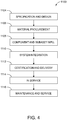
- illustrative method 1100 may include specification and design (block 1104) of aircraft 1102 and material procurement (block 1106).
- component and subassembly manufacturing (block 1108) and system integration (block 1110) of aircraft 1102 may take place. Thereafter, aircraft 1102 may go through certification and delivery (block 1112) to be placed in service (block 1114). While in service, aircraft 1102 may be scheduled for routine maintenance and service (block 1116). Routine maintenance and service may include modification, reconfiguration, refurbish-ment, etc. of one or more systems of aircraft 1102.
- a system integrator may include, without limitation, any number of aircraft manufacturers and major-system subcontractors; a third party may include, without limitation, any number of vendors, subcontractors, and suppliers; and an operator may be an airline, leasing company, military entity, service organization, and so on.
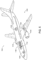
- aircraft 1102 produced by illustrative method 1100 may include airframe 1118 with a plurality of high-level systems 1120 and interior 1122.
- high-level systems 1120 include one or more of propulsion system 1124, electrical system 1126, hydraulic system 1128, and environmental system 1130. Any number of other systems may be included.
- propulsion system 1124 one or more of propulsion system 1124, electrical system 1126, hydraulic system 1128, and environmental system 1130. Any number of other systems may be included.
- propulsion system 1124 include one or more of propulsion system 1124, electrical system 1126, hydraulic system 1128, and environmental system 1130. Any number of other systems may be included.
- propulsion system 1124 include one or more of propulsion system 1124, electrical system 1126, hydraulic system 1128, and environmental system 1130. Any number of other systems may be included.
- electrical system 1126 electrical system 1126
- hydraulic system 1128 hydraulic system 1128
- environmental system 1130 any number of other systems may be included.
- Any number of other systems may be included.
- Apparatus(es) and method(s) shown or described herein may be employed during any one or more of the stages of the manufacturing and service method 1100.
- components or subassemblies corresponding to component and subassembly manufacturing (block 1108) may be fabricated or manufactured in a manner similar to components or subassemblies produced while aircraft 1102 is in service (block 1114).
- one or more examples of the apparatus(es), method(s), or combination thereof may be utilized during production stages 1108 and 1110, for example, by substantially expediting assembly of or reducing the cost of aircraft 1102.
- one or more examples of the apparatus or method realizations, or a combination thereof may be utilized, for example and without limitation, while aircraft 1102 is in service (block 1114) and/or during maintenance and service (block 1116).
Landscapes
- Engineering & Computer Science (AREA)
- Chemical & Material Sciences (AREA)
- Materials Engineering (AREA)
- Manufacturing & Machinery (AREA)
- Mechanical Engineering (AREA)
- Physics & Mathematics (AREA)
- Optics & Photonics (AREA)
- Composite Materials (AREA)
- Textile Engineering (AREA)
- Structural Engineering (AREA)
- Civil Engineering (AREA)
- Ceramic Engineering (AREA)
- Robotics (AREA)
Claims (15)
- Système (100) pour la fabrication additive d'un objet (102), le système (100) comprenant :une source d'alimentation en fibres (122), configurée pour distribuer des fibres allongées (108) ;une source d'alimentation en résine (124), configurée pour appliquer une résine (110) aux fibres allongées (108), distribuées depuis la source d'alimentation en fibres (122), pour créer une ligne de matière première (106), comprenant les fibres allongées (108) au moins partiellement encapsulées dans la résine (110), qui est dans un premier état non durci non rigide ;un mécanisme de rigidification (112) pour recevoir la ligne de matière première (106) avec la résine (110) dans le premier état non durci non rigide, le mécanisme de rigidification (112) étant configuré pour transformer la résine (110) de la ligne de matière première (106) du premier état non durci non rigide en un état non durci rigide, et la ligne de matière première (106) et la résine (110) étant plus rigides lorsque la résine (110) est dans l'état non durci rigide que lorsque la résine (110) est dans le premier état non durci non rigide ;un guide de délivrance (116) pour recevoir la ligne de matière première (106) depuis le mécanisme de rigidification (112) avec la résine (110) dans l'état non durci rigide, le guide de délivrance (116) étant configuré pour déposer la ligne de matière première (106) le long d'un chemin d'impression (114) ;un mécanisme d'avance (126), configuré pour faire avancer la ligne de matière première (106) à travers le guide de délivrance (116) ;un mécanisme de dérigidification (118), configuré pour transformer la résine (110) de la ligne de matière première (106), lorsque la ligne de matière première (106) passe à travers le guide de délivrance (116) ou lorsque la ligne de matière première (106) sort du guide de délivrance (116), de l'état non durci rigide en un deuxième état non durci non rigide, de telle sorte que, avant que la ligne de matière première (106) soit déposée le long du chemin d'impression (114) par le guide de délivrance (116), la résine (110) de la ligne de matière première (106), sortant du guide de délivrance (116), est dans le deuxième état non durci non rigide, la ligne de matière première (106) et la résine (110) étant moins rigides lorsque la résine (110) est dans le deuxième état non durci non rigide que lorsque la résine (110) est dans l'état non durci rigide ; etun mécanisme de durcissement (120), configuré pour transformer la résine (110) de la ligne de matière première (106), déposée par le guide de délivrance (116) le long du chemin d'impression (114), du deuxième état non durci non rigide en un état au moins partiellement durci.
- Système (100) selon la revendication 1, dans lequel :la ligne de matière première (106) dans le premier état non durci non rigide a un module de cisaillement inférieur ou égal à 0,1 GPa ;la ligne de matière première (106) dans l'état non durci rigide a un module de cisaillement supérieur à 0,1 GPa ; etla ligne de matière première (106) dans le deuxième état non durci non rigide a un module de cisaillement inférieur ou égal à 0,1 GPa.
- Système (100) selon la revendication 1 ou 2, dans lequel :le mécanisme de rigidification (112) est configuré pour extraire de la chaleur de la résine (110) de la ligne de matière première (106) dans le premier état non durci non rigide pour transformer la résine (110) de la ligne de matière première (106) du premier état non durci non rigide à l'état non durci rigide ; etle mécanisme de dérigidification (118) est configuré pour chauffer la résine (110) de la ligne de matière première (106) dans l'état non durci rigide pour transformer la résine (110) de la ligne de matière première (106) de l'état non durci rigide au deuxième état non durci non rigide.
- Système (100) selon l'une quelconque des revendications 1 à 3, comprenant en outre un système de contrôle (130), dans lequel :le système de contrôle (130) comprend au moins un capteur (132), configuré pour détecter au moins une caractéristique physique associée à la ligne de matière première (106) ; etle système de contrôle (130) est configuré pour contrôler activement au moins un mécanisme parmi le mécanisme de rigidification (112), le mécanisme d'avance (126), le mécanisme de dérigidification (118) et le mécanisme de durcissement (120), au moins en partie sur la base de l'au moins une caractéristique physique associée à la ligne de matière première (106).
- Système (100) selon la revendication 4, dans lequel le système de contrôle (130) est configuré pour contrôler activement le mécanisme de rigidification (112), au moins en partie sur la base de l'au moins une caractéristique physique associée à la ligne de matière première (106), pour contrôler la rigidité de la résine (110) dans l'état non durci rigide.
- Système (100) selon la revendication 4 ou 5, dans lequel le système de contrôle (130) est configuré pour contrôler activement le mécanisme d'avance (126), au moins en partie sur la base de l'au moins une caractéristique physique associée à la ligne de matière première (106), pour contrôler une vitesse d'avance de la ligne de matière première (106).
- Système (100) selon l'une quelconque des revendications 4 à 6, dans lequel le système de contrôle (130) est configuré pour contrôler activement le mécanisme de dérigidification (118), au moins en partie sur la base de l'au moins une caractéristique physique associée à la ligne de matière première (106), pour contrôler la rigidité de la résine (110) dans le deuxième état non durci non rigide.
- Système (100) selon l'une quelconque des revendications 4 à 7, dans lequel le système de contrôle (130) est configuré pour contrôler activement le mécanisme de durcissement (120), au moins en partie sur la base de l'au moins une caractéristique physique associée à la ligne de matière première (106), pour contrôler une vitesse de durcissement de la résine (110) de la ligne de matière première (106).
- Système (100) selon l'une quelconque des revendications 1 à 8, comprenant en outre un dispositif de chauffage de chemin d'impression (138), configuré pour chauffer le chemin d'impression (114) devant le guide de délivrance (116) lorsque le guide de délivrance (116) dépose la ligne de matière première (106) le long du chemin d'impression (114).
- Système (100) selon l'une quelconque des revendications 1 à 9, comprenant en outre un dispositif de chauffage de ligne de matière première déposée (140), configuré pour chauffer la ligne de matière première (106) après que la ligne de matière première (106) a été déposée par le guide de délivrance (116).
- Procédé (200) de fabrication additive d'un objet (102), le procédé (200) comprenant :l'application d'une résine (110) dans un premier état non durci non rigide à des fibres allongées (108) pour créer une ligne de matière première (106), la ligne de matière première (106) comprenant les fibres allongées (108) au moins partiellement encapsulées dans la résine (110) ;la transformation de la résine (110) de la ligne de matière première (106) du premier état non durci non rigide en un état non durci rigide, la ligne de matière première (106) et la résine (110) étant plus rigides lorsque la résine (110) est dans l'état non durci rigide que lorsque la résine (110) est dans le premier état non durci non rigide ;l'introduction de la ligne de matière première (106) dans un guide de délivrance (116) avec la résine (110) de la ligne de matière première (106) dans l'état non durci rigide ;la transformation de la résine (110) de la ligne de matière première (106) de l'état non durci rigide en un deuxième état non durci non rigide lorsque la ligne de matière première (106) passe à travers le guide de délivrance (116) ou lorsque la ligne de matière première (106) sort du guide de délivrance (116), la ligne de matière première (106) et la résine (110) étant moins rigides lorsque la résine (110) est dans le deuxième état non durci non rigide que lorsque la résine (110) est dans l'état non durci rigide ;le dépôt de la ligne de matière première (106) le long d'un chemin d'impression (114), avec la résine (110) de la ligne de matière première (106) dans le deuxième état non durci non rigide, au moyen du guide de délivrance (116) ; etle durcissement au moins partiel de la résine (110) de la ligne de matière première (106) après que la ligne de matière première (106) a été déposée par le guide de délivrance (116) le long du chemin d'impression (114).
- Procédé (200) selon la revendication 11, dans lequel :la ligne de matière première (106) dans le premier état non durci non rigide a un module de cisaillement inférieur ou égal à 0,1 GPa ;la ligne de matière première (106) dans l'état non durci rigide a un module de cisaillement supérieur à 0,1 GPa ; etla ligne de matière première (106) dans le deuxième état non durci non rigide a un module de cisaillement inférieur ou égal à 0,1 GPa.
- Procédé (200) selon la revendication 11 ou 12, dans lequel :la transformation de la résine (110) de la ligne de matière première (106) du premier état non durci non rigide à l'état non durci rigide comprend l'extraction de chaleur de la résine (110) de la ligne de matière première (106) dans le premier état non durci non rigide ; etla transformation de la résine (110) de la ligne de matière première (106) de l'état non durci rigide au deuxième état non durci non rigide lorsque la ligne de matière première (106) passe à travers le guide de délivrance (116) ou lorsque la ligne de matière première (106) sort du guide de délivrance (116) comprend le chauffage de la résine (110) de la ligne de matière première (106) dans l'état non durci rigide.
- Procédé (200) selon l'une quelconque des revendications 11 à 13, comprenant en outre :la détection d'au moins une caractéristique physique associée à la ligne de matière première (106) ; eten réponse à la détection de l'au moins une caractéristique physique associée à la ligne de matière première (106), le contrôle actif d'au moins une opération parmi :la transformation de la résine (110) de la ligne de matière première (106) du premier état non durci non rigide à l'état non durci rigide ;l'introduction de la ligne de matière première (106) dans le guide de délivrance (116) avec la résine (110) de la ligne de matière première (106) dans l'état non durci rigide ;la transformation de la résine (110) de la ligne de matière première (106) de l'état non durci rigide au deuxième état non durci non rigide lorsque la ligne de matière première (106) passe à travers le guide de délivrance (116) ou lorsque la ligne de matière première (106) sort du guide de délivrance (116) ; etle durcissement au moins partiel de la résine (110) de la ligne de matière première (106) après que la ligne de matière première (106) a été déposée par le guide de délivrance (116) le long du chemin d'impression (114).
- Procédé (200) selon la revendication 14, dans lequel le contrôle actif de la transformation de la résine (110) de la ligne de matière première (106) du premier état non durci non rigide à l'état non durci rigide comprend le contrôle de la rigidité de la résine (110) dans l'état non durci rigide.
Applications Claiming Priority (1)
| Application Number | Priority Date | Filing Date | Title |
|---|---|---|---|
| US15/642,705 US10814550B2 (en) | 2017-07-06 | 2017-07-06 | Methods for additive manufacturing |
Publications (2)
| Publication Number | Publication Date |
|---|---|
| EP3424708A1 EP3424708A1 (fr) | 2019-01-09 |
| EP3424708B1 true EP3424708B1 (fr) | 2021-09-15 |
Family
ID=62062839
Family Applications (2)
| Application Number | Title | Priority Date | Filing Date |
|---|---|---|---|
| EP18168731.0A Not-in-force EP3424708B1 (fr) | 2017-07-06 | 2018-04-23 | Fabrication additive avec une gaine renforcée de fibres |
| EP18168735.1A Active EP3424687B1 (fr) | 2017-07-06 | 2018-04-23 | Fabrication additive avec une gaine renforcée de fibres |
Family Applications After (1)
| Application Number | Title | Priority Date | Filing Date |
|---|---|---|---|
| EP18168735.1A Active EP3424687B1 (fr) | 2017-07-06 | 2018-04-23 | Fabrication additive avec une gaine renforcée de fibres |
Country Status (4)
| Country | Link |
|---|---|
| US (2) | US10814550B2 (fr) |
| EP (2) | EP3424708B1 (fr) |
| JP (1) | JP7223516B2 (fr) |
| CN (2) | CN109203453A (fr) |
Families Citing this family (16)
| Publication number | Priority date | Publication date | Assignee | Title |
|---|---|---|---|---|
| US10457033B2 (en) | 2016-11-07 | 2019-10-29 | The Boeing Company | Systems and methods for additively manufacturing composite parts |
| WO2018189062A1 (fr) * | 2017-04-13 | 2018-10-18 | Philips Lighting Holding B.V. | Procédé d'impression 3d d'un article 3d |
| US10525635B2 (en) | 2017-09-15 | 2020-01-07 | The Boeing Company | Systems and methods for creating feedstock lines for additive manufacturing of an object |
| US10611081B2 (en) | 2017-09-15 | 2020-04-07 | The Boeing Company | Systems and methods for creating feedstock lines for additive manufacturing of an object |
| US10618222B2 (en) | 2017-09-15 | 2020-04-14 | The Boeing Company | Systems and methods for additively manufacturing an object |
| US10603890B2 (en) | 2017-09-15 | 2020-03-31 | The Boeing Company | Systems and methods for creating feedstock lines for additive manufacturing of an object |
| CN109676925B (zh) * | 2019-01-16 | 2021-08-24 | 广西富乐科技有限责任公司 | 一种3d打印机工作时材料供给装置 |
| US20200238603A1 (en) * | 2019-01-25 | 2020-07-30 | Continuous Composites Inc. | System for additively manufacturing composite structure |
| US11858064B2 (en) * | 2019-02-19 | 2024-01-02 | Illinois Tool Works Inc. | Path planning systems and methods for additive manufacturing |
| CN111361151B (zh) * | 2020-03-17 | 2021-04-27 | 重庆市美客无双智能科技有限公司 | 一种混色3d打印喷头组件以及混色方法 |
| CN111873359A (zh) * | 2020-06-04 | 2020-11-03 | 武义斯汀纳睿三维科技有限公司 | 一种连续纤维芯状复合线材的制备方法及3d打印头 |
| IT202100006800A1 (it) * | 2021-03-22 | 2022-09-22 | Spherecube S R L | Metodo e sistema di stampa tridimensionale di materiali compositi |
| US12409496B2 (en) | 2022-04-27 | 2025-09-09 | The Boeing Company | Pre-heating methods for performing electron beam powder bed fusion |
| US12485621B2 (en) | 2022-08-25 | 2025-12-02 | The Boeing Company | Methods of additively manufacturing a manufactured component and systems that perform the methods |
| US12343933B2 (en) | 2022-08-25 | 2025-07-01 | The Boeing Company | Methods of additively manufacturing a manufactured component and systems that perform the methods |
| US12269110B2 (en) * | 2023-01-26 | 2025-04-08 | Goodrich Corporation | Field-assisted friction stir additive manufacturing |
Family Cites Families (108)
| Publication number | Priority date | Publication date | Assignee | Title |
|---|---|---|---|---|
| US3600272A (en) | 1968-08-29 | 1971-08-17 | Scott Paper Co | Polyethyleneimine cured epoxy-modified paper |
| US3813976A (en) | 1973-06-20 | 1974-06-04 | Guardian Industries | Photographic print cutter |
| US3993726A (en) | 1974-01-16 | 1976-11-23 | Hercules Incorporated | Methods of making continuous length reinforced plastic articles |
| US4154634A (en) | 1977-09-22 | 1979-05-15 | Plas/Steel Products, Inc. | Method for fabricating improved fiber reinforced plastic rods having a smooth surface |
| JPS6052208B2 (ja) | 1979-09-25 | 1985-11-18 | 住友化学工業株式会社 | 炭素繊維トウの製造方法 |
| US4435246A (en) | 1982-10-04 | 1984-03-06 | Franchise Mailing Systems | Label dispensing and applying apparatus |
| US4943472A (en) | 1988-03-03 | 1990-07-24 | Basf Aktiengesellschaft | Improved preimpregnated material comprising a particulate thermosetting resin suitable for use in the formation of a substantially void-free fiber-reinforced composite article |
| US5495328A (en) | 1988-04-18 | 1996-02-27 | 3D Systems, Inc. | Apparatus and method for calibrating and normalizing a stereolithographic apparatus |
| CA1336483C (fr) | 1989-01-30 | 1995-08-01 | Hatsuo Ishida | Procede pour la preparation de composites |
| US5121329A (en) | 1989-10-30 | 1992-06-09 | Stratasys, Inc. | Apparatus and method for creating three-dimensional objects |
| US5204124A (en) | 1990-10-09 | 1993-04-20 | Stanley Secretan | Continuous extruded bead object fabrication apparatus |
| US5398193B1 (en) | 1993-08-20 | 1997-09-16 | Alfredo O Deangelis | Method of three-dimensional rapid prototyping through controlled layerwise deposition/extraction and apparatus therefor |
| US5936861A (en) * | 1997-08-15 | 1999-08-10 | Nanotek Instruments, Inc. | Apparatus and process for producing fiber reinforced composite objects |
| US6129872A (en) | 1998-08-29 | 2000-10-10 | Jang; Justin | Process and apparatus for creating a colorful three-dimensional object |
| US6149856A (en) | 1998-11-13 | 2000-11-21 | Anvik Corporation | Ultraviolet-based, large-area scanning system for photothermal processing of composite structures |
| US6395210B1 (en) | 1999-05-12 | 2002-05-28 | A&P Technology, Inc. | Pultrusion method and device for forming composites using pre-consolidated braids |
| US6722872B1 (en) | 1999-06-23 | 2004-04-20 | Stratasys, Inc. | High temperature modeling apparatus |
| US6214279B1 (en) | 1999-10-02 | 2001-04-10 | Nanotek Instruments, Inc. | Apparatus and process for freeform fabrication of composite reinforcement preforms |
| US6362388B1 (en) | 1999-11-30 | 2002-03-26 | Gregory J. Lucas | Adhesive bandage |
| US20050104241A1 (en) | 2000-01-18 | 2005-05-19 | Objet Geometried Ltd. | Apparatus and method for three dimensional model printing |
| US6369157B1 (en) * | 2000-01-21 | 2002-04-09 | Cyclics Corporation | Blend material including macrocyclic polyester oligomers and processes for polymerizing the same |
| US6574523B1 (en) | 2000-05-05 | 2003-06-03 | 3D Systems, Inc. | Selective control of mechanical properties in stereolithographic build style configuration |
| US6899777B2 (en) | 2001-01-02 | 2005-05-31 | Advanced Ceramics Research, Inc. | Continuous fiber reinforced composites and methods, apparatuses, and compositions for making the same |
| WO2003085022A1 (fr) | 2002-03-29 | 2003-10-16 | Huntsman International Llc | Procede d'enroulement de filaments |
| US20040119188A1 (en) | 2002-12-20 | 2004-06-24 | Lowe Kenneth A. | Impregnated fiber precursors and methods and systems for producing impregnated fibers and fabricating composite structures |
| DE20307300U1 (de) | 2003-05-09 | 2003-09-11 | Uniwell Wellrohr GmbH, 96106 Ebern | Isolierschlauch mit Schlitz |
| US20050023719A1 (en) | 2003-07-28 | 2005-02-03 | Nielsen Jeffrey Allen | Separate solidification of build material and support material in solid freeform fabrication system |
| DE10342882A1 (de) | 2003-09-15 | 2005-05-19 | Trumpf Werkzeugmaschinen Gmbh + Co. Kg | Vorrichtung und Verfahren zur Herstellung eines dreidimensionalen Formkörpers |
| JP2005319634A (ja) | 2004-05-07 | 2005-11-17 | Roland Dg Corp | 三次元造形装置および三次元造形方法 |
| US7939003B2 (en) | 2004-08-11 | 2011-05-10 | Cornell Research Foundation, Inc. | Modular fabrication systems and methods |
| US20060070697A1 (en) | 2004-09-23 | 2006-04-06 | Ingersoll Machine Tools, Inc. | Method and apparatus for directing resin-impregnated tape |
| US7114943B1 (en) | 2005-05-11 | 2006-10-03 | 3D Systems, Inc. | Post processor for three-dimensional objects |
| US7681615B2 (en) | 2005-08-04 | 2010-03-23 | The Boeing Company | Tow width adaptable placement head device and method |
| DE102005050665A1 (de) | 2005-10-20 | 2007-04-26 | Bego Medical Gmbh | Schichtweises Herstellungsverfahren mit Korngrößenbeeinflussung |
| US7879177B2 (en) | 2006-11-20 | 2011-02-01 | The Boeing Company | Apparatus and method for composite material trim-on-the-fly |
| US8691037B2 (en) | 2006-12-14 | 2014-04-08 | The Boeing Company | Method for minimizing fiber distortion during fabrication of one-piece composite barrel section |
| US7891964B2 (en) | 2007-02-12 | 2011-02-22 | Stratasys, Inc. | Viscosity pump for extrusion-based deposition systems |
| US20080315462A1 (en) | 2007-06-25 | 2008-12-25 | General Electric Company | Systems and methods for monitoring a composite cure cycle |
| US8151854B2 (en) | 2007-10-16 | 2012-04-10 | Ingersoll Machine Tools, Inc. | Fiber placement machine platform system having interchangeable head and creel assemblies |
| DK2052693T4 (da) | 2007-10-26 | 2021-03-15 | Envisiontec Gmbh | Proces og fri-formfabrikationssystem til at fremstille en tredimensionel genstand |
| US9132587B2 (en) | 2008-04-10 | 2015-09-15 | Stratasys Ltd. | System and method for three dimensional model printing |
| US7942987B2 (en) | 2008-06-24 | 2011-05-17 | Stratasys, Inc. | System and method for building three-dimensional objects with metal-based alloys |
| GB0818468D0 (en) | 2008-10-08 | 2008-11-12 | Alta Innovations Ltd | A resin applicator |
| US7960024B2 (en) | 2009-01-27 | 2011-06-14 | Milliken & Company | Multi-layered fiber |
| US8920697B2 (en) | 2010-09-17 | 2014-12-30 | Stratasys, Inc. | Method for building three-dimensional objects in extrusion-based additive manufacturing systems using core-shell consumable filaments |
| CA2809278C (fr) | 2010-09-17 | 2015-10-20 | Stratasys, Inc. | Materiaux consommables semi-cristallins destines a etre utilises dans des systemes de fabrication d'additifs bases sur l'extrusion |
| US20120077397A1 (en) | 2010-09-23 | 2012-03-29 | Saint-Gobain Adfors Canada, Ltd. | Reinforcing carbon fibers and material containing the fibers |
| WO2012149127A1 (fr) | 2011-04-29 | 2012-11-01 | Ticona Llc | Matrice à passage à grille diffusant un écoulement et procédé d'imprégnation de stratifils de fibres |
| AU2012350360B2 (en) | 2011-12-16 | 2017-08-10 | Alan ERDMAN | Apparatus and method for retreading tyres |
| US8985497B2 (en) | 2011-12-22 | 2015-03-24 | Stratasys, Inc. | Consumable assembly with payout tube for additive manufacturing system |
| KR20130108026A (ko) | 2012-03-23 | 2013-10-02 | 주식회사 엘지화학 | 유기발광소자 |
| GB201210851D0 (en) * | 2012-06-19 | 2012-08-01 | Eads Uk Ltd | Extrusion-based additive manufacturing system |
| GB201212629D0 (en) | 2012-07-16 | 2012-08-29 | Prec Engineering Technologies Ltd | A machine tool |
| US9511543B2 (en) | 2012-08-29 | 2016-12-06 | Cc3D Llc | Method and apparatus for continuous composite three-dimensional printing |
| IN2015DN02636A (fr) | 2012-09-21 | 2015-09-18 | Conformis Inc | |
| US9102098B2 (en) | 2012-12-05 | 2015-08-11 | Wobbleworks, Inc. | Hand-held three-dimensional drawing device |
| US20140265000A1 (en) | 2013-03-14 | 2014-09-18 | Bayer Materialscience, Llc | Water-clear aliphatic polyurethane pultrusion formulations and processes |
| US9138940B2 (en) | 2013-03-15 | 2015-09-22 | Type A Machines, Inc. | Winchester print head |
| US9527240B2 (en) | 2013-03-15 | 2016-12-27 | Stratasys, Inc. | Additive manufacturing system and method for printing three-dimensional parts using velocimetry |
| GB201304968D0 (en) * | 2013-03-19 | 2013-05-01 | Eads Uk Ltd | Extrusion-based additive manufacturing |
| CN107399076B (zh) | 2013-03-22 | 2020-03-27 | 格雷戈里·托马斯·马克 | 三维打印 |
| US9694544B2 (en) | 2013-03-22 | 2017-07-04 | Markforged, Inc. | Methods for fiber reinforced additive manufacturing |
| US9126365B1 (en) * | 2013-03-22 | 2015-09-08 | Markforged, Inc. | Methods for composite filament fabrication in three dimensional printing |
| US9149988B2 (en) | 2013-03-22 | 2015-10-06 | Markforged, Inc. | Three dimensional printing |
| US9156205B2 (en) * | 2013-03-22 | 2015-10-13 | Markforged, Inc. | Three dimensional printer with composite filament fabrication |
| US9186848B2 (en) * | 2013-03-22 | 2015-11-17 | Markforged, Inc. | Three dimensional printing of composite reinforced structures |
| US9126367B1 (en) * | 2013-03-22 | 2015-09-08 | Markforged, Inc. | Three dimensional printer for fiber reinforced composite filament fabrication |
| DE102013103973A1 (de) | 2013-04-19 | 2014-10-23 | Fit Fruth Innovative Technologien Gmbh | Werkzeugkopf |
| US9789462B2 (en) | 2013-06-25 | 2017-10-17 | The Boeing Company | Apparatuses and methods for accurate structure marking and marking-assisted structure locating |
| CN107443721A (zh) | 2013-07-17 | 2017-12-08 | 马克弗盖德公司 | 用于纤维增强的添加制造的装置 |
| US9751260B2 (en) | 2013-07-24 | 2017-09-05 | The Boeing Company | Additive-manufacturing systems, apparatuses and methods |
| GB201313840D0 (en) | 2013-08-02 | 2013-09-18 | Rolls Royce Plc | Method of Manufacturing a Component |
| US20150174824A1 (en) | 2013-12-19 | 2015-06-25 | Karl Joseph Gifford | Systems and methods for 3D printing with multiple exchangeable printheads |
| US9102099B1 (en) | 2014-02-05 | 2015-08-11 | MetaMason, Inc. | Methods for additive manufacturing processes incorporating active deposition |
| CN103817937B (zh) | 2014-02-19 | 2016-04-06 | 浙江大学宁波理工学院 | 蠕动泵式3d打印笔 |
| JP6306907B2 (ja) | 2014-03-14 | 2018-04-04 | 富士機械製造株式会社 | 立体造形物の製造方法及び製造装置 |
| US9650537B2 (en) | 2014-04-14 | 2017-05-16 | Ut-Battelle, Llc | Reactive polymer fused deposition manufacturing |
| WO2015189600A2 (fr) | 2014-06-09 | 2015-12-17 | Ex Scintilla Ltd | Procédés de traitement de matériau et appareil associé |
| CN106660268A (zh) | 2014-06-16 | 2017-05-10 | 沙特基础工业全球技术有限公司 | 在材料挤出增材制造中用于增强粘结的方法和装置 |
| US9931778B2 (en) * | 2014-09-18 | 2018-04-03 | The Boeing Company | Extruded deposition of fiber reinforced polymers |
| EP3200612B1 (fr) | 2014-09-29 | 2021-05-26 | Natural Machines, Inc. | Appareil et procédé de chauffage et de cuisson d'aliments au moyen de faisceaux laser et d'un rayonnement électromagnétique |
| EP3218160A4 (fr) | 2014-11-14 | 2018-10-17 | Nielsen-Cole, Cole | Techniques et systèmes d'impression en 3d pour former des matériaux composites |
| JP2016107454A (ja) | 2014-12-04 | 2016-06-20 | ローランドディー.ジー.株式会社 | 三次元造形装置 |
| US20160159009A1 (en) | 2014-12-05 | 2016-06-09 | Philip L. Canale | Combined thermal and uv/visible light curing stereolithography |
| KR101995650B1 (ko) | 2015-01-30 | 2019-09-24 | 휴렛-팩커드 디벨롭먼트 컴퍼니, 엘.피. | 3차원 물체 제조 기법 |
| JP6625653B2 (ja) | 2015-02-02 | 2019-12-25 | マッシビット スリーディー プリンティング テクノロジーズ リミテッド | 3d物体プリンティング用の硬化システム |
| WO2016126779A1 (fr) | 2015-02-05 | 2016-08-11 | Carbon3D, Inc. | Procédé de fabrication additive par fabrication via des zones multiples |
| JP6808635B2 (ja) | 2015-03-03 | 2021-01-06 | シグニファイ ホールディング ビー ヴィSignify Holding B.V. | 改良された機械的特性のための、硬化性追従材料を挿入することによる、付加製造技術で製造された複数の部分のスティッチング |
| DE102015002967A1 (de) | 2015-03-07 | 2016-10-13 | Willi Viktor LAUER | 3D-Druckwerkzeug und 3D-Druck von Bündeln |
| US10913202B2 (en) | 2015-03-19 | 2021-02-09 | The Board Of Regents, The University Of Texas System | Structurally integrating metal objects into additive manufactured structures |
| US10016932B2 (en) | 2015-05-13 | 2018-07-10 | The Boeing Company | Fiber placement system and method with modulated laser scan heating |
| WO2017004042A1 (fr) | 2015-06-29 | 2017-01-05 | Applied Materials, Inc. | Impression 3d à température régulée |
| CN107921707A (zh) | 2015-07-17 | 2018-04-17 | 应用材料公司 | 具有冷却剂系统的增材制造 |
| US10201941B2 (en) * | 2015-07-31 | 2019-02-12 | The Boeing Company | Systems for additively manufacturing composite parts |
| US10195784B2 (en) * | 2015-07-31 | 2019-02-05 | The Boeing Company | Systems for additively manufacturing composite parts |
| US10232570B2 (en) * | 2015-07-31 | 2019-03-19 | The Boeing Company | Systems for additively manufacturing composite parts |
| US10343355B2 (en) * | 2015-07-31 | 2019-07-09 | The Boeing Company | Systems for additively manufacturing composite parts |
| US10343330B2 (en) * | 2015-07-31 | 2019-07-09 | The Boeing Company | Systems for additively manufacturing composite parts |
| US10232550B2 (en) * | 2015-07-31 | 2019-03-19 | The Boeing Company | Systems for additively manufacturing composite parts |
| CN105109042A (zh) * | 2015-09-14 | 2015-12-02 | 武汉华星光电技术有限公司 | 一种3d打印系统 |
| US12269211B2 (en) * | 2016-05-26 | 2025-04-08 | Wisconsin Alumni Research Foundation | Additive manufacturing process continuous reinforcement fibers and high fiber volume content |
| CN106273497B (zh) * | 2016-08-31 | 2019-02-19 | 青岛理工大学 | 一种多材料复合3d打印机及其工作方法和应用 |
| US10457033B2 (en) | 2016-11-07 | 2019-10-29 | The Boeing Company | Systems and methods for additively manufacturing composite parts |
| US11440261B2 (en) | 2016-11-08 | 2022-09-13 | The Boeing Company | Systems and methods for thermal control of additive manufacturing |
| US10766241B2 (en) | 2016-11-18 | 2020-09-08 | The Boeing Company | Systems and methods for additive manufacturing |
| JP6892983B2 (ja) | 2016-11-29 | 2021-06-23 | キョーラク株式会社 | 3dプリンタ及び3次元造形方法 |
| US10843452B2 (en) | 2016-12-01 | 2020-11-24 | The Boeing Company | Systems and methods for cure control of additive manufacturing |
| US10759159B2 (en) | 2017-05-31 | 2020-09-01 | The Boeing Company | Feedstock lines for additive manufacturing |
-
2017
- 2017-07-06 US US15/642,705 patent/US10814550B2/en not_active Expired - Fee Related
-
2018
- 2018-04-23 EP EP18168731.0A patent/EP3424708B1/fr not_active Not-in-force
- 2018-04-23 EP EP18168735.1A patent/EP3424687B1/fr active Active
- 2018-06-08 CN CN201810585185.5A patent/CN109203453A/zh active Pending
- 2018-06-08 CN CN201810585294.7A patent/CN109203454A/zh active Pending
- 2018-06-29 JP JP2018124087A patent/JP7223516B2/ja active Active
-
2020
- 2020-09-15 US US17/021,281 patent/US11318674B2/en not_active Expired - Fee Related
Also Published As
| Publication number | Publication date |
|---|---|
| US10814550B2 (en) | 2020-10-27 |
| JP7223516B2 (ja) | 2023-02-16 |
| US11318674B2 (en) | 2022-05-03 |
| EP3424687A1 (fr) | 2019-01-09 |
| US20200406540A1 (en) | 2020-12-31 |
| CN109203454A (zh) | 2019-01-15 |
| EP3424687B1 (fr) | 2022-06-08 |
| US20190009462A1 (en) | 2019-01-10 |
| JP2019031074A (ja) | 2019-02-28 |
| EP3424708A1 (fr) | 2019-01-09 |
| CN109203453A (zh) | 2019-01-15 |
Similar Documents
| Publication | Publication Date | Title |
|---|---|---|
| US11318674B2 (en) | Systems and methods for additive manufacturing | |
| US11318675B2 (en) | Systems and methods for additive manufacturing | |
| CA2900778C (fr) | Depot extrude de polymeres renforces par des fibres | |
| EP3124212B1 (fr) | Système de fabrication de parties composites de manière additive | |
| US20170028638A1 (en) | Systems and methods for additively manufacturing composite parts | |
| CA3068714C (fr) | Systemes et procedes de placement automatise de fibres et articles produits a partir de celles-ci | |
| EP3456508B1 (fr) | Système et procédé de fabrication additive d'un objet | |
| CA3002479C (fr) | Systemes et methodes de fabrication d'additif de production | |
| US10828848B2 (en) | Automated fiber-placement systems and methods | |
| US10828849B2 (en) | Articles produced from automated fiber-placement systems and methods | |
| EP3456517B1 (fr) | Systèmes et procédés pour la création de lignes d'alimentation pour la fabrication additive d'un objet | |
| US20190047209A1 (en) | Additive manufacturing fiber tows with bindments and related systems and methods |
Legal Events
| Date | Code | Title | Description |
|---|---|---|---|
| PUAI | Public reference made under article 153(3) epc to a published international application that has entered the european phase |
Free format text: ORIGINAL CODE: 0009012 |
|
| STAA | Information on the status of an ep patent application or granted ep patent |
Free format text: STATUS: REQUEST FOR EXAMINATION WAS MADE |
|
| 17P | Request for examination filed |
Effective date: 20180423 |
|
| AK | Designated contracting states |
Kind code of ref document: A1 Designated state(s): AL AT BE BG CH CY CZ DE DK EE ES FI FR GB GR HR HU IE IS IT LI LT LU LV MC MK MT NL NO PL PT RO RS SE SI SK SM TR |
|
| AX | Request for extension of the european patent |
Extension state: BA ME |
|
| RIC1 | Information provided on ipc code assigned before grant |
Ipc: B29K 105/08 20060101ALN20210331BHEP Ipc: B29L 31/30 20060101ALN20210331BHEP Ipc: B29C 70/24 20060101ALI20210331BHEP Ipc: B29C 70/38 20060101ALI20210331BHEP Ipc: B29C 64/295 20170101ALI20210331BHEP Ipc: B29C 64/209 20170101ALI20210331BHEP Ipc: B29C 64/165 20170101ALI20210331BHEP Ipc: B33Y 30/00 20150101ALI20210331BHEP Ipc: B33Y 10/00 20150101AFI20210331BHEP |
|
| GRAP | Despatch of communication of intention to grant a patent |
Free format text: ORIGINAL CODE: EPIDOSNIGR1 |
|
| STAA | Information on the status of an ep patent application or granted ep patent |
Free format text: STATUS: GRANT OF PATENT IS INTENDED |
|
| RIC1 | Information provided on ipc code assigned before grant |
Ipc: B29K 105/08 20060101ALN20210407BHEP Ipc: B29L 31/30 20060101ALN20210407BHEP Ipc: B29C 70/24 20060101ALI20210407BHEP Ipc: B29C 70/38 20060101ALI20210407BHEP Ipc: B29C 64/295 20170101ALI20210407BHEP Ipc: B29C 64/209 20170101ALI20210407BHEP Ipc: B29C 64/165 20170101ALI20210407BHEP Ipc: B33Y 30/00 20150101ALI20210407BHEP Ipc: B33Y 10/00 20150101AFI20210407BHEP |
|
| RIN1 | Information on inventor provided before grant (corrected) |
Inventor name: TORRES, FARAON Inventor name: EVANS, NICK S. Inventor name: HARRISON, SAMUEL F. Inventor name: WILENSKI, MARK S. |
|
| INTG | Intention to grant announced |
Effective date: 20210510 |
|
| GRAS | Grant fee paid |
Free format text: ORIGINAL CODE: EPIDOSNIGR3 |
|
| GRAA | (expected) grant |
Free format text: ORIGINAL CODE: 0009210 |
|
| STAA | Information on the status of an ep patent application or granted ep patent |
Free format text: STATUS: THE PATENT HAS BEEN GRANTED |
|
| AK | Designated contracting states |
Kind code of ref document: B1 Designated state(s): AL AT BE BG CH CY CZ DE DK EE ES FI FR GB GR HR HU IE IS IT LI LT LU LV MC MK MT NL NO PL PT RO RS SE SI SK SM TR |
|
| REG | Reference to a national code |
Ref country code: CH Ref legal event code: EP |
|
| REG | Reference to a national code |
Ref country code: DE Ref legal event code: R096 Ref document number: 602018023479 Country of ref document: DE |
|
| REG | Reference to a national code |
Ref country code: IE Ref legal event code: FG4D |
|
| REG | Reference to a national code |
Ref country code: AT Ref legal event code: REF Ref document number: 1430221 Country of ref document: AT Kind code of ref document: T Effective date: 20211015 |
|
| REG | Reference to a national code |
Ref country code: LT Ref legal event code: MG9D |
|
| REG | Reference to a national code |
Ref country code: NL Ref legal event code: MP Effective date: 20210915 |
|
| PG25 | Lapsed in a contracting state [announced via postgrant information from national office to epo] |
Ref country code: SE Free format text: LAPSE BECAUSE OF FAILURE TO SUBMIT A TRANSLATION OF THE DESCRIPTION OR TO PAY THE FEE WITHIN THE PRESCRIBED TIME-LIMIT Effective date: 20210915 Ref country code: RS Free format text: LAPSE BECAUSE OF FAILURE TO SUBMIT A TRANSLATION OF THE DESCRIPTION OR TO PAY THE FEE WITHIN THE PRESCRIBED TIME-LIMIT Effective date: 20210915 Ref country code: FI Free format text: LAPSE BECAUSE OF FAILURE TO SUBMIT A TRANSLATION OF THE DESCRIPTION OR TO PAY THE FEE WITHIN THE PRESCRIBED TIME-LIMIT Effective date: 20210915 Ref country code: HR Free format text: LAPSE BECAUSE OF FAILURE TO SUBMIT A TRANSLATION OF THE DESCRIPTION OR TO PAY THE FEE WITHIN THE PRESCRIBED TIME-LIMIT Effective date: 20210915 Ref country code: NO Free format text: LAPSE BECAUSE OF FAILURE TO SUBMIT A TRANSLATION OF THE DESCRIPTION OR TO PAY THE FEE WITHIN THE PRESCRIBED TIME-LIMIT Effective date: 20211215 Ref country code: LT Free format text: LAPSE BECAUSE OF FAILURE TO SUBMIT A TRANSLATION OF THE DESCRIPTION OR TO PAY THE FEE WITHIN THE PRESCRIBED TIME-LIMIT Effective date: 20210915 Ref country code: BG Free format text: LAPSE BECAUSE OF FAILURE TO SUBMIT A TRANSLATION OF THE DESCRIPTION OR TO PAY THE FEE WITHIN THE PRESCRIBED TIME-LIMIT Effective date: 20211215 |
|
| REG | Reference to a national code |
Ref country code: AT Ref legal event code: MK05 Ref document number: 1430221 Country of ref document: AT Kind code of ref document: T Effective date: 20210915 |
|
| PG25 | Lapsed in a contracting state [announced via postgrant information from national office to epo] |
Ref country code: LV Free format text: LAPSE BECAUSE OF FAILURE TO SUBMIT A TRANSLATION OF THE DESCRIPTION OR TO PAY THE FEE WITHIN THE PRESCRIBED TIME-LIMIT Effective date: 20210915 Ref country code: GR Free format text: LAPSE BECAUSE OF FAILURE TO SUBMIT A TRANSLATION OF THE DESCRIPTION OR TO PAY THE FEE WITHIN THE PRESCRIBED TIME-LIMIT Effective date: 20211216 |
|
| PG25 | Lapsed in a contracting state [announced via postgrant information from national office to epo] |
Ref country code: AT Free format text: LAPSE BECAUSE OF FAILURE TO SUBMIT A TRANSLATION OF THE DESCRIPTION OR TO PAY THE FEE WITHIN THE PRESCRIBED TIME-LIMIT Effective date: 20210915 |
|
| PG25 | Lapsed in a contracting state [announced via postgrant information from national office to epo] |
Ref country code: IS Free format text: LAPSE BECAUSE OF FAILURE TO SUBMIT A TRANSLATION OF THE DESCRIPTION OR TO PAY THE FEE WITHIN THE PRESCRIBED TIME-LIMIT Effective date: 20220115 Ref country code: SM Free format text: LAPSE BECAUSE OF FAILURE TO SUBMIT A TRANSLATION OF THE DESCRIPTION OR TO PAY THE FEE WITHIN THE PRESCRIBED TIME-LIMIT Effective date: 20210915 Ref country code: SK Free format text: LAPSE BECAUSE OF FAILURE TO SUBMIT A TRANSLATION OF THE DESCRIPTION OR TO PAY THE FEE WITHIN THE PRESCRIBED TIME-LIMIT Effective date: 20210915 Ref country code: RO Free format text: LAPSE BECAUSE OF FAILURE TO SUBMIT A TRANSLATION OF THE DESCRIPTION OR TO PAY THE FEE WITHIN THE PRESCRIBED TIME-LIMIT Effective date: 20210915 Ref country code: PT Free format text: LAPSE BECAUSE OF FAILURE TO SUBMIT A TRANSLATION OF THE DESCRIPTION OR TO PAY THE FEE WITHIN THE PRESCRIBED TIME-LIMIT Effective date: 20220117 Ref country code: PL Free format text: LAPSE BECAUSE OF FAILURE TO SUBMIT A TRANSLATION OF THE DESCRIPTION OR TO PAY THE FEE WITHIN THE PRESCRIBED TIME-LIMIT Effective date: 20210915 Ref country code: NL Free format text: LAPSE BECAUSE OF FAILURE TO SUBMIT A TRANSLATION OF THE DESCRIPTION OR TO PAY THE FEE WITHIN THE PRESCRIBED TIME-LIMIT Effective date: 20210915 Ref country code: ES Free format text: LAPSE BECAUSE OF FAILURE TO SUBMIT A TRANSLATION OF THE DESCRIPTION OR TO PAY THE FEE WITHIN THE PRESCRIBED TIME-LIMIT Effective date: 20210915 Ref country code: EE Free format text: LAPSE BECAUSE OF FAILURE TO SUBMIT A TRANSLATION OF THE DESCRIPTION OR TO PAY THE FEE WITHIN THE PRESCRIBED TIME-LIMIT Effective date: 20210915 Ref country code: CZ Free format text: LAPSE BECAUSE OF FAILURE TO SUBMIT A TRANSLATION OF THE DESCRIPTION OR TO PAY THE FEE WITHIN THE PRESCRIBED TIME-LIMIT Effective date: 20210915 Ref country code: AL Free format text: LAPSE BECAUSE OF FAILURE TO SUBMIT A TRANSLATION OF THE DESCRIPTION OR TO PAY THE FEE WITHIN THE PRESCRIBED TIME-LIMIT Effective date: 20210915 |
|
| REG | Reference to a national code |
Ref country code: DE Ref legal event code: R097 Ref document number: 602018023479 Country of ref document: DE |
|
| PLBE | No opposition filed within time limit |
Free format text: ORIGINAL CODE: 0009261 |
|
| STAA | Information on the status of an ep patent application or granted ep patent |
Free format text: STATUS: NO OPPOSITION FILED WITHIN TIME LIMIT |
|
| PG25 | Lapsed in a contracting state [announced via postgrant information from national office to epo] |
Ref country code: DK Free format text: LAPSE BECAUSE OF FAILURE TO SUBMIT A TRANSLATION OF THE DESCRIPTION OR TO PAY THE FEE WITHIN THE PRESCRIBED TIME-LIMIT Effective date: 20210915 |
|
| 26N | No opposition filed |
Effective date: 20220616 |
|
| PG25 | Lapsed in a contracting state [announced via postgrant information from national office to epo] |
Ref country code: SI Free format text: LAPSE BECAUSE OF FAILURE TO SUBMIT A TRANSLATION OF THE DESCRIPTION OR TO PAY THE FEE WITHIN THE PRESCRIBED TIME-LIMIT Effective date: 20210915 |
|
| REG | Reference to a national code |
Ref country code: CH Ref legal event code: PL |
|
| REG | Reference to a national code |
Ref country code: BE Ref legal event code: MM Effective date: 20220430 |
|
| PG25 | Lapsed in a contracting state [announced via postgrant information from national office to epo] |
Ref country code: MC Free format text: LAPSE BECAUSE OF FAILURE TO SUBMIT A TRANSLATION OF THE DESCRIPTION OR TO PAY THE FEE WITHIN THE PRESCRIBED TIME-LIMIT Effective date: 20210915 Ref country code: LU Free format text: LAPSE BECAUSE OF NON-PAYMENT OF DUE FEES Effective date: 20220423 Ref country code: LI Free format text: LAPSE BECAUSE OF NON-PAYMENT OF DUE FEES Effective date: 20220430 Ref country code: IT Free format text: LAPSE BECAUSE OF FAILURE TO SUBMIT A TRANSLATION OF THE DESCRIPTION OR TO PAY THE FEE WITHIN THE PRESCRIBED TIME-LIMIT Effective date: 20210915 Ref country code: CH Free format text: LAPSE BECAUSE OF NON-PAYMENT OF DUE FEES Effective date: 20220430 |
|
| PG25 | Lapsed in a contracting state [announced via postgrant information from national office to epo] |
Ref country code: BE Free format text: LAPSE BECAUSE OF NON-PAYMENT OF DUE FEES Effective date: 20220430 |
|
| PG25 | Lapsed in a contracting state [announced via postgrant information from national office to epo] |
Ref country code: IE Free format text: LAPSE BECAUSE OF NON-PAYMENT OF DUE FEES Effective date: 20220423 |
|
| P01 | Opt-out of the competence of the unified patent court (upc) registered |
Effective date: 20230516 |
|
| PGFP | Annual fee paid to national office [announced via postgrant information from national office to epo] |
Ref country code: FR Payment date: 20230425 Year of fee payment: 6 Ref country code: DE Payment date: 20230427 Year of fee payment: 6 |
|
| PGFP | Annual fee paid to national office [announced via postgrant information from national office to epo] |
Ref country code: GB Payment date: 20230427 Year of fee payment: 6 |
|
| PG25 | Lapsed in a contracting state [announced via postgrant information from national office to epo] |
Ref country code: HU Free format text: LAPSE BECAUSE OF FAILURE TO SUBMIT A TRANSLATION OF THE DESCRIPTION OR TO PAY THE FEE WITHIN THE PRESCRIBED TIME-LIMIT; INVALID AB INITIO Effective date: 20180423 |
|
| PG25 | Lapsed in a contracting state [announced via postgrant information from national office to epo] |
Ref country code: MK Free format text: LAPSE BECAUSE OF FAILURE TO SUBMIT A TRANSLATION OF THE DESCRIPTION OR TO PAY THE FEE WITHIN THE PRESCRIBED TIME-LIMIT Effective date: 20210915 Ref country code: CY Free format text: LAPSE BECAUSE OF FAILURE TO SUBMIT A TRANSLATION OF THE DESCRIPTION OR TO PAY THE FEE WITHIN THE PRESCRIBED TIME-LIMIT Effective date: 20210915 |
|
| PG25 | Lapsed in a contracting state [announced via postgrant information from national office to epo] |
Ref country code: TR Free format text: LAPSE BECAUSE OF FAILURE TO SUBMIT A TRANSLATION OF THE DESCRIPTION OR TO PAY THE FEE WITHIN THE PRESCRIBED TIME-LIMIT Effective date: 20210915 |
|
| PG25 | Lapsed in a contracting state [announced via postgrant information from national office to epo] |
Ref country code: MT Free format text: LAPSE BECAUSE OF FAILURE TO SUBMIT A TRANSLATION OF THE DESCRIPTION OR TO PAY THE FEE WITHIN THE PRESCRIBED TIME-LIMIT Effective date: 20210915 |
|
| REG | Reference to a national code |
Ref country code: DE Ref legal event code: R119 Ref document number: 602018023479 Country of ref document: DE |
|
| GBPC | Gb: european patent ceased through non-payment of renewal fee |
Effective date: 20240423 |
|
| PG25 | Lapsed in a contracting state [announced via postgrant information from national office to epo] |
Ref country code: DE Free format text: LAPSE BECAUSE OF NON-PAYMENT OF DUE FEES Effective date: 20241105 |
|
| PG25 | Lapsed in a contracting state [announced via postgrant information from national office to epo] |
Ref country code: GB Free format text: LAPSE BECAUSE OF NON-PAYMENT OF DUE FEES Effective date: 20240423 |
|
| PG25 | Lapsed in a contracting state [announced via postgrant information from national office to epo] |
Ref country code: FR Free format text: LAPSE BECAUSE OF NON-PAYMENT OF DUE FEES Effective date: 20240430 |
|
| PG25 | Lapsed in a contracting state [announced via postgrant information from national office to epo] |
Ref country code: GB Free format text: LAPSE BECAUSE OF NON-PAYMENT OF DUE FEES Effective date: 20240423 Ref country code: FR Free format text: LAPSE BECAUSE OF NON-PAYMENT OF DUE FEES Effective date: 20240430 Ref country code: DE Free format text: LAPSE BECAUSE OF NON-PAYMENT OF DUE FEES Effective date: 20241105 |