EP3424788B1 - Véhicule de travail agricole - Google Patents
Véhicule de travail agricole Download PDFInfo
- Publication number
- EP3424788B1 EP3424788B1 EP18163100.3A EP18163100A EP3424788B1 EP 3424788 B1 EP3424788 B1 EP 3424788B1 EP 18163100 A EP18163100 A EP 18163100A EP 3424788 B1 EP3424788 B1 EP 3424788B1
- Authority
- EP
- European Patent Office
- Prior art keywords
- implement
- working vehicle
- control device
- braking
- attachment
- Prior art date
- Legal status (The legal status is an assumption and is not a legal conclusion. Google has not performed a legal analysis and makes no representation as to the accuracy of the status listed.)
- Active
Links
Images
Classifications
-
- B—PERFORMING OPERATIONS; TRANSPORTING
- B60—VEHICLES IN GENERAL
- B60T—VEHICLE BRAKE CONTROL SYSTEMS OR PARTS THEREOF; BRAKE CONTROL SYSTEMS OR PARTS THEREOF, IN GENERAL; ARRANGEMENT OF BRAKING ELEMENTS ON VEHICLES IN GENERAL; PORTABLE DEVICES FOR PREVENTING UNWANTED MOVEMENT OF VEHICLES; VEHICLE MODIFICATIONS TO FACILITATE COOLING OF BRAKES
- B60T8/00—Arrangements for adjusting wheel-braking force to meet varying vehicular or ground-surface conditions, e.g. limiting or varying distribution of braking force
- B60T8/17—Using electrical or electronic regulation means to control braking
- B60T8/176—Brake regulation specially adapted to prevent excessive wheel slip during vehicle deceleration, e.g. ABS
- B60T8/1766—Proportioning of brake forces according to vehicle axle loads, e.g. front to rear of vehicle
-
- B—PERFORMING OPERATIONS; TRANSPORTING
- B60—VEHICLES IN GENERAL
- B60T—VEHICLE BRAKE CONTROL SYSTEMS OR PARTS THEREOF; BRAKE CONTROL SYSTEMS OR PARTS THEREOF, IN GENERAL; ARRANGEMENT OF BRAKING ELEMENTS ON VEHICLES IN GENERAL; PORTABLE DEVICES FOR PREVENTING UNWANTED MOVEMENT OF VEHICLES; VEHICLE MODIFICATIONS TO FACILITATE COOLING OF BRAKES
- B60T8/00—Arrangements for adjusting wheel-braking force to meet varying vehicular or ground-surface conditions, e.g. limiting or varying distribution of braking force
- B60T8/17—Using electrical or electronic regulation means to control braking
- B60T8/1701—Braking or traction control means specially adapted for particular types of vehicles
-
- B—PERFORMING OPERATIONS; TRANSPORTING
- B60—VEHICLES IN GENERAL
- B60T—VEHICLE BRAKE CONTROL SYSTEMS OR PARTS THEREOF; BRAKE CONTROL SYSTEMS OR PARTS THEREOF, IN GENERAL; ARRANGEMENT OF BRAKING ELEMENTS ON VEHICLES IN GENERAL; PORTABLE DEVICES FOR PREVENTING UNWANTED MOVEMENT OF VEHICLES; VEHICLE MODIFICATIONS TO FACILITATE COOLING OF BRAKES
- B60T8/00—Arrangements for adjusting wheel-braking force to meet varying vehicular or ground-surface conditions, e.g. limiting or varying distribution of braking force
- B60T8/26—Arrangements for adjusting wheel-braking force to meet varying vehicular or ground-surface conditions, e.g. limiting or varying distribution of braking force characterised by producing differential braking between front and rear wheels
- B60T8/30—Arrangements for adjusting wheel-braking force to meet varying vehicular or ground-surface conditions, e.g. limiting or varying distribution of braking force characterised by producing differential braking between front and rear wheels responsive to load
Definitions
- the present invention relates to an agricultural work vehicle with a device for accommodating an attachment and a device for accommodating counterweights, as well as a chassis comprising at least two axles, a front axle and a rear axle, on which torque transmission means are arranged, with a brake system that can be controlled by a control device, which comprises at least one braking device acting on at least one of the axles or the torque transmission means arranged thereon. Furthermore, the invention relates to a method for operating a rural work vehicle according to the preamble of claim 11.
- the EP 2 009 329 B1 describes a harvesting machine with a control device for regulating the hydraulic drive unit of a travel drive as a function of static and dynamic machine parameters.
- a static machine parameter is formed by the respective front attachment arranged on the harvesting machine, which enters the control device with specification of the type designation and equipment.
- the interchangeable attachments determine the wheel or axle load on the drive wheels and thus influence the traction and slip behavior of the drive wheels.
- the static and dynamic machine parameters are used to adjust the displacement of the hydraulic drive units to optimize traction and prevent slippage.
- the agricultural working vehicle designed as a tractor has front and rear device interfaces for attaching different working devices and/or ballasts counterweights.
- the tractor also has a chassis with a front axle and a rear axle, on which wheels are arranged as torque transmission means.
- a braking system is provided for braking the tractor, which has braking devices acting on the wheels.
- the braking system is controlled by a control device.
- the braking system is controlled as a function of the static and dynamic chassis forces acting on the axles in the vertical direction, which are detected by a sensor arrangement.
- the control device calculates a distribution of the occurring axle forces in order to derive from the calculated distribution for the braking devices a specification with regard to the distribution of the braking forces provided by the braking system.
- the detection of the static and dynamic chassis forces requires the arrangement of wheel and axle sensors in order to distribute the available brake pressure depending on the chassis forces.
- a rural working vehicle is proposed, with a device for accommodating an attachment and a device for accommodating counterweights, as well as one comprising at least two axles Running gear, a front axle and a rear axle, on which torque transmission means are arranged, and with a controllable by a control device brake system, which comprises at least one braking device acting on at least one of the axles or the torque transmission means arranged thereon.
- Torque transmission means are understood to mean tires or crawler tracks, which can each be arranged exclusively or in combination with one another on the axles.
- the control device be set up to, depending on at least one attachment-specific property which can be determined by the control device using information provided about the type of attachment, one of the braking system on the Front axle provided maximum brake pressure and / or adjust a brake pressure curve.
- This has the advantage that the braking system provides the braking power as required, ie adapted to the actual total weight of the working vehicle and the respective attachment mounted on it.
- the invention provides a need-based widening of the brake pressure, which ensures that the work vehicle with the attached implement comes to a standstill within a legally prescribed braking distance.
- the control of the braking system according to the invention by the control device takes place both when driving in fields and when driving on the road when an attachment is connected to the working vehicle.
- Implement type information can be provided in a number of ways.
- a preferred possibility is that when the attachment is connected to the work vehicle, the type of attachment is automatically determined by the control device.
- the provision of information about the type of attachment can also take place based on a manual input by an operator if this cannot be determined automatically, for example. In this way, the same braking distances can be achieved landscape working vehicle with different types of attachments.
- the need-based provision of braking power leads to a reduced locking tendency of the front axle, which is associated with improved controllability and more stable handling of the work vehicle during braking.
- control device can be set up to increase the maximum brake pressure provided as the weight of the attachment increases.
- the negative acceleration per unit of time increases as the weight of the attachment increases.
- the brake system can include a load-dependent brake valve.
- a specific brake pressure can be set by means of the load-dependent brake valve, which can be determined from the weight of the working vehicle and that of the attachment mounted on it. That is, the load-sensing brake valve is adjustable depending on the machine load. In this way, the front axle can be braked to different extents depending on the attached implement, with the resulting braking distance always being within the legally specified braking distances within which the working vehicle must come to a standstill.
- the load-dependent brake valve can be designed as a continuous valve, in particular as a proportional valve.
- control device is set up to determine the counterweight to be accommodated as a function of the attachment type and the at least one attachment-specific property.
- An arrangement of counterweights adapted to the respective attachment results in less ballast on the working vehicle.
- the counterweight that is specific to the respective type of attachment and is to be arranged on the work vehicle can be brought to the knowledge of an operator by the control device so that this can be taken into account when equipping the work vehicle. This leads to a reduction in the overall weight of the working vehicle, which is associated with lower fuel consumption.
- the at least one braking device can expediently be designed as a friction brake, with at least one of the axles being assigned a friction brake to at least each of the torque transmission means. Friction brakes can thus be assigned to each of the torque transmission means, both the front axle and the at least one further rear axle.
- the friction brakes can be disk brakes, disc brakes or drum brakes.
- At least one of the axles of the utility vehicle can be assigned a hydrostatic travel drive, which is set up to partially or completely generate a braking effect.
- a braking effect can be generated entirely or partially by the pressure difference in the hydrostatic circuit of the drive. In this way, a purely hydrostatic braking device could be implemented, which would do without a friction brake as the service brake.
- the control device can preferably be set up to control a hydraulic motor or a hydraulic pump of the hydrostatic travel drive in order to generate at least an additional braking force as a function of at least one attachment-specific property.
- the braking effect of the friction brakes on the front axle and/or rear axle can be supported as a function of the load.
- the braking force can be generated solely by the at least one hydraulic motor or the at least one hydraulic pump, with the actuation taking place as a function of at least one attachment-specific property.
- control device can be set up to adjust a maximum brake pressure provided by the brake system on the rear axle and/or on an additional axle assigned to the work vehicle as a function of the at least one attachment-specific property.
- the additional axle can be a third axle of the working vehicle or act an axle arranged on the attachment.
- the additional axle also has braking devices, which can be subjected to a braking pressure by the braking system in a manner according to the invention.
- a further attachment-specific property can be a support arrangement located on the attachment.
- the support arrangement can include support wheels or skids which are integrated into the attachment or are attached to the attachment by means of an attachment device.
- the latter arrangement of the support arrangement by means of the hitch comes into play when the working vehicle is driving on the road. Since the presence of a support arrangement on the attachment serves, among other things, to relieve the axle to which the attachment is arranged adjacent, usually the front axle, this also affects the required braking power.
- the agricultural working vehicle can preferably be designed as a tractor, self-propelled combine harvester or forage harvester.
- the object is also achieved by a method for operating an agricultural working vehicle, in particular a forage harvester.
- the agricultural work vehicle includes a device that picks up an attachment and a device that picks up counterweights, as well as a chassis that has at least two axles, a front axle and a rear axle, on which torque transmission means are arranged, with the at least one axle or the torque transmission means arranged thereon is acted upon by a braking system which is controlled by a control device.
- a maximum brake pressure provided by the brake system at least on the front axle and/or a brake pressure curve is adjusted as a function of at least one attachment-specific property, which is determined by the control device based on information provided about the type of attachment picked up, so that as the mass of the attachment increases the braking effect increases.
- the provision of the recorded attachment type is carried out when connecting the attachment to the work vehicle. This can be done automatically by recognizing the attachment, for example by the transmission of data by the attachment to the control device of the work vehicle, which enables identification of the type of attachment or by reading out a memory provided on the attachment, which stores specific data for the attachment. Of course, this data can also be entered manually by a person operating the work vehicle using an input/output device.
- the weight of the attachment is determined as an attachment-specific property, which, in conjunction with the weight of the work vehicle, is taken as a basis for adjusting the maximum brake pressure provided on the front axle.
- the necessary counterweight to be taken up can be determined and displayed.
- the control device can be in signaling connection with an input/output device which is arranged in a cab of the utility vehicle.
- the maximum brake pressure available on the front axle can be changed in such a way that the braking effect increases.
- At least one load-dependent brake valve can preferably be activated to change the maximum brake pressure provided.
- the displacement of a hydraulic motor and/or a hydraulic pump of a hydraulic travel drive can be changed as a function of the at least one attachment-specific property.
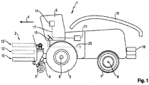
- attachment 1 shows a schematic representation of an agricultural working vehicle with attachment 2 arranged on it.
- the agricultural working vehicle is designed as a forage harvester 1 .
- the attachment 2 is designed to be foldable in order not to exceed the maximum width permitted for road travel. Accordingly, the attachment 2 is unfolded during harvesting.
- the term attachment includes any attachment or attachment that can be attached to an agricultural working vehicle, regardless of whether it can be folded up or not.
- the attachment or attachment 2 includes integrated support wheels 3, which support the attachment 2 relative to the ground. The support force applied by the support wheels 3 can be adjustable by an actuator in each case.
- the forage harvester 1 shown in a side view is driven by front main drive wheels 5 arranged on a front axle 6 and steered by steerable rear wheels 7 arranged on a rear axle 8 .
- the rear wheels 7 can also be driven.
- the front wheels and/or rear wheels of the forage harvester shown can also be designed as belt, caterpillar or chain drives. The following explanations also apply accordingly in this case.
- a feed device 4 is provided in the front area, through which the harvested crop is fed into the interior of the forage harvester 1 .
- the harvested crop arrives from the intake device 4 through processing devices for the harvested crop (not shown), in particular a chopping device, an optional conditioning device and a post-acceleration device, to an ejection device 10 which is arranged behind a driver's cab 9 .
- the ejection device 10 conveys the harvested crop into a trailer which is carried alongside or behind the forage harvester 1 and which is pulled by a tractor, for example.
- Means are provided on the intake device 4, on which the attachment 2 can be hung.
- a main frame of the attachment 2 runs into and out of the image plane and thus transversely, i.e. offset by an angle of about 90°, to the direction of travel F of the vehicle 1.
- the foldable attachment 2 has a middle section 12 and outer sections 12 ', 12
- the outer sections 12′, 12′′ in the transport position of the attachment 2 are indicated with dashed lines.
- the forage harvester 1 includes a control device 13 which is used to control a braking system of the forage harvester 1 .
- the control device 13 is connected to an input/output device 14 in the cabin 9 by a signal and control line 17 .
- a brake pedal 15 is arranged in the cab 9, which is actuated by an operator in order to bring the forage harvester 1 to a standstill.
- the brake pedal 15 is also connected to the control device 13 by a signal and control line 17 .
- counterweights 16 are arranged, which are used for ballasting.
- the counterweights 16 provide a corresponding load on the rear axle 8 in order to at least reduce the lifting tendency of the forage harvester 1 when braking.
- the front axle 6 can be relieved by the ballasting.
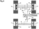
- FIG. 2 is a schematic representation of a chassis of the forage harvester 1. Due to the arrangement of the attachment 2 on the intake device 4, the common center of gravity of the attachment and the harvesting machine is closer to the front axle 6 than to the rear axle 8 of the chassis, so that the proportion of the weight of the Forage harvester 1, which carries the front axle 6, is greater than the part carried by the rear axle 8. In order to evenly distribute the weight of the machine on the surface being driven on, the front wheels 5 are larger than the steerable rear wheels 7. Since the center of gravity of the machine is higher than the axles 6, 8, the proportion of the load carried by the front axle 1 increases weight even if the machine is decelerated while driving.
- Each wheel 5, 7 is provided with a braking device 18, 19 designed as a friction brake, in this case a—preferably wet—disc brake in the case of the front wheels 5 and a drum brake in the case of the rear wheels 4.
- the braking devices 18 and 19 can each also be used as disc brakes be executed.
- the braking devices 18 of the front wheels 5 and the braking devices 19 of the rear wheels 7 belong to two separate brake circuits 20, 21, both of which are externally controlled by the same brake pedal 15, but use two brake pressure valves 22, 23 actuated by the brake pedal 15 for this purpose .
- the brake pressure valves 22, 23 can use different characteristic curves or differ in terms of valve type, so that the relationship between the actuating force exerted on the brake pedal 15 by an operator of the forage harvester 1 and the resulting brake pressure in the brake circuits 20 or 21 is different.
- At least one hydraulic motor 24 (hydraulic motor), which is part of a hydrostatic travel drive of the forage harvester 1, is assigned to the front axle 6 designed as a drive axle.
- the at least one hydraulic motor 24 is hydraulically connected to a hydraulic pump, not shown, whose displacement is variable.
- the hydraulic motor 24 and the hydraulic pump can each have a Be formed provided unit swash plate, ie as an adjustable axial piston motor or adjustable axial piston pump.
- At least the brake pressure valve 22 of the brake circuit 20 of the front axle 6 is designed as a continuous valve.
- the brake pressure valves 22 and 23 and the hydraulic motor 24 are connected to the control device 13 by signal and control lines 25 .
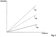
- a graphic which shows an example of the relationship between the external force applied to brake pedal 15 and the braking force generated by the braking system if, according to the invention, the braking system is controlled by control device 13 as a function of an attachment-specific property, in particular the weight of the respective attachment 2 is controlled.
- the graphic shows an example of three curves 26a, 26b and 26c of a braking force, with the braking force curve 26a being an example of an attachment 2 which is characterized by its low weight, the braking force curve in 26b being characteristic of an attachment 2 with a medium weight and the braking force curve 26c, which occurs when attachments 2 are heavy.
- the respective weight of the attachment 2 is determined in particular by its working width.
- the proportional braking force curve depending on the respective combination of work vehicle 1 and attachment 2 is advantageous.
- the adjustment of the braking force depending in particular on the weight of the attachment 2 allows the same braking distances to be achieved with different total machine weights.
- a large number of braking force curves can be stored in the control device 13 so that they can be called up.
- the braking force curves 26a, 26b, 26c can be adjusted.
- the attachment-specific property is determined by the control device 13 using information provided about the attachment type.
- the attachment type can be entered manually by the operator using the input/output device 14 .
- the information provided about the attachment type is used by the control device 13 in order to call up the corresponding attachment-specific properties in a database that can be stored in a memory device of the control device 13 .
- control device 13 can be set up to automatically determine the attachment type of the respective attachment 2 by automatically transferring data between the attachment 2 and the control device 13 when the attachment 2 is connected to the intake device 4 .
- the provided attachment-specific properties are not just limited to the weight of the attached attachment 2.
- the working width of the attachment 2 can be called up or information about whether a support arrangement such as the support wheels 3 is provided on the attachment 2.
- control device 13 is set up to use the attachment-specific properties in order to determine the weight of the counterweights 16 to be attached at the rear.
- This information is transmitted from the control device 13 to the input/output device 14 so that it is available to the operator of the forage harvester 1 so that it can be called up. Accordingly, the operator can adjust the counterweights 16 to the actual weight of the attachment 2, which leads to a reduction in the total weight of the unit made up of the forage harvester 1 and the attachment 2. In addition to fuel savings due to the lower overall machine weight, this leads to a reduction in the required braking power or the maximum braking pressure that has to be provided by the braking system.
- the brake system is actuated by the control device 13 depending on the attachment-specific property only for the brake pressure valve 22 , which is arranged in the brake circuit 20 of the front axle 6 . Corresponding dependencies are stored in the control device 13 for this purpose, so that a predetermined maximum brake pressure is set by the brake pressure valve 22 as a function of the recognized attachment. Accordingly, the front axle 6 is braked to different extents depending on the attachment 2 .
- a development provides that the brake pressure valve 23 of the brake circuit 21 of the rear axle 8 is also controlled by the control device as a function of the attachment-specific property of the attachment 2 .
- the attachment 2 is provided with a spacer arrangement designed as support wheels 3, a braking device can also be arranged on the support wheels 3, which can also be controlled by the control device 13 in the finding according to the manner.
- Another aspect can be the at least load-dependent support of the braking effect of the braking system by the hydraulic motor or motors 24 .
- the braking power of the braking system can be increased, particularly with heavy attachments, by the control device 13 controlling the hydraulic pump feeding the at least one hydraulic motor 24 in such a way that the displacement of the hydraulic pump is at least reduced.
- the hydrostatic travel drive is set up for the partial or complete generation of a braking effect.
- the control device 13 is set up to control the hydraulic motor 24 or a hydraulic pump of the hydrostatic travel drive to generate an additional braking force as a function of the at least one attachment-specific property.
Landscapes
- Engineering & Computer Science (AREA)
- Transportation (AREA)
- Mechanical Engineering (AREA)
- Regulating Braking Force (AREA)
- Control Of Driving Devices And Active Controlling Of Vehicle (AREA)
Claims (15)
- Véhicule de travail agricole (1), avec un dispositif (4) pour loger un appareil rapporté (2) et un système pour loger des contrepoids (16), ainsi qu'avec un train de roulement comprenant au moins deux essieux, un essieu avant (6) et un essieu arrière (8), sur lesquels sont disposés des moyens de transfert de couple de rotation (5, 7), et avec un système de freinage pouvant être piloté par un système de commande (13), lequel comprend au moins un système de freinage (18, 19, 24) agissant sur au moins un des essieux (6, 8) ou sur les moyens de transfert de couple de rotation (5, 7) disposés sur ceux-ci, caractérisé en ce que le système de commande (13) est mis au point pour adapter une pression de freinage maximale fournie par le système de freinage à l'essieu avant (6) et/ou une variation de pression de freinage (26a, 26b, 26c) en fonction d'au moins une propriété spécifique à l'appareil rapporté, laquelle peut être déterminée par le système de commande (13) à l'aide d'une information fournie sur le type de l'appareil rapporté.
- Véhicule de travail agricole (1) selon la revendication 1, caractérisé en ce que le système de commande (13) est mis au point pour augmenter la pression de freinage maximale fournie au fur et à mesure que le poids de l'appareil rapporté (2) augmente.
- Véhicule de travail agricole (1) selon l'une quelconque des revendications 1 ou 2, caractérisé en ce que le système de freinage comprend au moins une soupape de pression de freinage (22) dépendant de la charge.
- Véhicule de travail agricole (1) selon l'une quelconque des revendications 1 à 3, caractérisé en ce que le système de commande (13) est mis au point pour définir le contrepoids (16) à absorber en fonction du type de l'appareil rapporté et de l'au moins une propriété spécifique à l'appareil rapporté.
- Véhicule de travail agricole (1) selon l'une quelconque des revendications 1 à 4, caractérisé en ce que l'au moins un système de freinage (18, 19) est réalisé en tant que frein à friction, dans lequel un frein à friction est associé à au moins chacun des moyens de transfert de couple de rotation (5) d'un des essieux (6, 8).
- Véhicule de travail agricole (1) selon l'une quelconque des revendications précédentes, caractérisé en ce qu'est associé à au moins un des essieux (6, 8) un entraînement de déplacement hydrostatique, qui est mis au point pour produire en partie ou en totalité un effet de freinage.
- Véhicule de travail agricole (1) selon la revendication 6, caractérisé en ce que le système de commande (13) est mis au point pour piloter un moteur hydraulique (24) ou une pompe hydraulique de l'entraînement de déplacement hydrostatique pour produire une force de freinage supplémentaire en fonction de l'au moins une propriété spécifique à l'appareil rapporté.
- Véhicule de travail agricole (1) selon l'une quelconque des revendications précédentes, caractérisé en ce que le système de commande (13) est mis au point pour adapter une pression de freinage maximale fournie par le système de freinage à l'essieu arrière (8) et/ou à un essieu supplémentaire associé au véhicule de travail en fonction de l'au moins une propriété spécifique à l'appareil rapporté.
- Véhicule de travail agricole selon l'une quelconque des revendications précédentes, caractérisé en ce qu'une autre propriété spécifique à l'appareil rapporté est un ensemble de soutien (3) se trouvant sur l'appareil rapporté.
- Véhicule de travail agricole (1) selon l'une quelconque des revendications précédentes, caractérisé en ce que le véhicule de travail agricole est réalisé en tant que tracteur, que moissonneuse-batteuse automotrice ou que ramasseuse-hacheuse.
- Procédé pour faire fonctionner un véhicule de travail agricole (1), en particulier une ramasseuse-hacheuse, comprenant un dispositif (4), qui loge un appareil rapporté (2), et un système, qui loge des contrepoids (16), ainsi qu'avec un train de roulement comprenant au moins deux essieux, un essieu avant (6) et un essieu arrière (8), sur lesquels sont disposés des moyens de transfert de couple de rotation (5, 7), et avec un système de freinage agissant sur au moins un des essieux ou sur les moyens de transfert de couple de rotation (5, 7), lequel est piloté par un système de commande (13), caractérisé en ce qu'une pression de freinage maximale fournie par le système de freinage au moins à l'essieu avant (6) et/ou une variation de pression de freinage (26a, 26b, 26c) sont adaptées en fonction d'au moins une propriété spécifique à l'appareil rapporté, laquelle est déterminée par le système de commande (13) à l'aide d'une information fournie sur le type de l'appareil rapporté logé.
- Procédé selon la revendication 11, caractérisé en ce que le contrepoids (16) nécessaire à loger est défini et affiché en fonction du type de l'appareil rapporté et de l'au moins une propriété spécifique à l'appareil rapporté liée à celui-ci.
- Procédé selon l'une quelconque des revendications 11 ou 12, caractérisé en ce que la pression de freinage maximale disponible est modifiée sur l'essieu avant (6) au fur et à mesure que le poids de l'appareil rapporté (2) installé respectivement augmente de telle manière que l'effet de freinage augmente.
- Procédé selon l'une quelconque des revendications 11 à 13, caractérisé en ce qu'au moins une soupape de freinage (22) dépendant de la charge est pilotée pour modifier la pression de freinage fournie au maximum.
- Procédé selon l'une quelconque des revendications 11 à 14,
caractérisé en ce que le volume d'absorption d'un moteur hydraulique (24) d'un entraînement de déplacement hydraulique est modifié en fonction de l'au moins une propriété spécifique à l'appareil rapporté pour produire un effet de freinage supplémentaire.
Applications Claiming Priority (1)
| Application Number | Priority Date | Filing Date | Title |
|---|---|---|---|
| DE102017114917.1A DE102017114917A1 (de) | 2017-07-04 | 2017-07-04 | Landwirtschaftliches Arbeitsfahrzeug |
Publications (2)
| Publication Number | Publication Date |
|---|---|
| EP3424788A1 EP3424788A1 (fr) | 2019-01-09 |
| EP3424788B1 true EP3424788B1 (fr) | 2022-07-20 |
Family
ID=61911353
Family Applications (1)
| Application Number | Title | Priority Date | Filing Date |
|---|---|---|---|
| EP18163100.3A Active EP3424788B1 (fr) | 2017-07-04 | 2018-03-21 | Véhicule de travail agricole |
Country Status (2)
| Country | Link |
|---|---|
| EP (1) | EP3424788B1 (fr) |
| DE (1) | DE102017114917A1 (fr) |
Families Citing this family (3)
| Publication number | Priority date | Publication date | Assignee | Title |
|---|---|---|---|---|
| US11136744B2 (en) | 2019-10-31 | 2021-10-05 | Deere & Company | Vehicles with control systems to perform various functions based on payload weight and methods of operating the same |
| DE102020125639A1 (de) | 2020-10-01 | 2022-04-07 | Zf Cv Systems Global Gmbh | Fremdkraftbremsanlage eines Fahrzeugs und Verfahren zu deren Steuerung |
| DE102023120749A1 (de) * | 2023-08-04 | 2025-02-06 | Deere & Company | Heckgewichtzusammenbau zur Anbringung an einem Feldhäcksler |
Family Cites Families (5)
| Publication number | Priority date | Publication date | Assignee | Title |
|---|---|---|---|---|
| DE4210743A1 (de) * | 1992-04-01 | 1993-10-07 | Bosch Gmbh Robert | Zugmaschine |
| GB2376992B (en) * | 2001-05-18 | 2005-03-23 | Bamford Excavators Ltd | Vehicle |
| GB2439333A (en) * | 2006-06-20 | 2007-12-27 | Bamford Excavators Ltd | Loading machine with ABS |
| DE102007030168A1 (de) | 2007-06-27 | 2009-01-08 | Claas Selbstfahrende Erntemaschinen Gmbh | Elektronische Steuerung für die Antriebseinheit eines Fahrzeugs |
| DE102014105758A1 (de) | 2014-04-24 | 2015-10-29 | Claas Tractor Sas | Landwirtschaftliches Nutzfahrzeug, insbesondere Traktor |
-
2017
- 2017-07-04 DE DE102017114917.1A patent/DE102017114917A1/de not_active Withdrawn
-
2018
- 2018-03-21 EP EP18163100.3A patent/EP3424788B1/fr active Active
Also Published As
| Publication number | Publication date |
|---|---|
| DE102017114917A1 (de) | 2019-01-10 |
| EP3424788A1 (fr) | 2019-01-09 |
Similar Documents
| Publication | Publication Date | Title |
|---|---|---|
| EP2387870B1 (fr) | Machine agricole dotée d'un appareil adaptable | |
| EP1582389B1 (fr) | Entraînement pour véhicule de travail | |
| EP2930086B1 (fr) | Moissonneuse automotrice | |
| EP2183950B1 (fr) | Moissonneuse agricole | |
| EP2977300B1 (fr) | Vehicule agricole | |
| DE102007021498A1 (de) | Aktives Bewegungssystem eines landwirtschaftlichen oder industriellen Nutzfahrzeugs | |
| EP1818245B1 (fr) | Remorque et procédé d'entraînement d'un remorque | |
| EP3424788B1 (fr) | Véhicule de travail agricole | |
| EP1488676B1 (fr) | Moissonneuse automotrice | |
| EP2363014A1 (fr) | Récolteuse dotée d'un élément de récolte et d'une roue d'appui | |
| EP2937252A1 (fr) | Véhicule agricole, notamment tracteur | |
| DE102013111426A1 (de) | Zusatzgerät für ein landwirtschaftliches Fahrzeug und landwirtschaftliches Fahrzeug | |
| EP3603376B1 (fr) | Machine de récolte doté d'une tête de récolte et d'une roue d'appui | |
| EP1473203B1 (fr) | véhicule remorqué utilisable sur route et hors route | |
| DE102008032104B4 (de) | Landmaschine | |
| EP3771601B1 (fr) | Procédé de fonctionnement d'un système de freinage d'un train agricole | |
| DE102015114055A1 (de) | Landwirtschaftliches Fahrzeug | |
| BE1022416B1 (de) | Selbstfahrende arbeitsmaschine mit hydrostatischem fahrantrieb | |
| DE69217278T2 (de) | Verbesserung für landwirtschaftliche Maschinen wie Aufsattelpflüge mit einer Hilfsantriebsvorrichtung | |
| DE102006046329B4 (de) | Arbeitsfahrzeug mit einer Kupplungsvorrichtung zum Anhängen eines Arbeitsgerätes | |
| EP2653324B1 (fr) | Moissonneuse agricole | |
| EP3569458B1 (fr) | Procédé de fonctionnement d'un système de freinage d'un tracteur agricole, système de freinage pour un tracteur agricole ainsi que tracteur agricole | |
| EP1674306B1 (fr) | Machine de travail agricole |
Legal Events
| Date | Code | Title | Description |
|---|---|---|---|
| PUAI | Public reference made under article 153(3) epc to a published international application that has entered the european phase |
Free format text: ORIGINAL CODE: 0009012 |
|
| STAA | Information on the status of an ep patent application or granted ep patent |
Free format text: STATUS: THE APPLICATION HAS BEEN PUBLISHED |
|
| AK | Designated contracting states |
Kind code of ref document: A1 Designated state(s): AL AT BE BG CH CY CZ DE DK EE ES FI FR GB GR HR HU IE IS IT LI LT LU LV MC MK MT NL NO PL PT RO RS SE SI SK SM TR |
|
| AX | Request for extension of the european patent |
Extension state: BA ME |
|
| STAA | Information on the status of an ep patent application or granted ep patent |
Free format text: STATUS: REQUEST FOR EXAMINATION WAS MADE |
|
| 17P | Request for examination filed |
Effective date: 20190709 |
|
| RBV | Designated contracting states (corrected) |
Designated state(s): AL AT BE BG CH CY CZ DE DK EE ES FI FR GB GR HR HU IE IS IT LI LT LU LV MC MK MT NL NO PL PT RO RS SE SI SK SM TR |
|
| GRAP | Despatch of communication of intention to grant a patent |
Free format text: ORIGINAL CODE: EPIDOSNIGR1 |
|
| STAA | Information on the status of an ep patent application or granted ep patent |
Free format text: STATUS: GRANT OF PATENT IS INTENDED |
|
| INTG | Intention to grant announced |
Effective date: 20220218 |
|
| GRAS | Grant fee paid |
Free format text: ORIGINAL CODE: EPIDOSNIGR3 |
|
| GRAA | (expected) grant |
Free format text: ORIGINAL CODE: 0009210 |
|
| STAA | Information on the status of an ep patent application or granted ep patent |
Free format text: STATUS: THE PATENT HAS BEEN GRANTED |
|
| AK | Designated contracting states |
Kind code of ref document: B1 Designated state(s): AL AT BE BG CH CY CZ DE DK EE ES FI FR GB GR HR HU IE IS IT LI LT LU LV MC MK MT NL NO PL PT RO RS SE SI SK SM TR |
|
| REG | Reference to a national code |
Ref country code: CH Ref legal event code: EP |
|
| REG | Reference to a national code |
Ref country code: DE Ref legal event code: R096 Ref document number: 502018010168 Country of ref document: DE |
|
| REG | Reference to a national code |
Ref country code: AT Ref legal event code: REF Ref document number: 1505353 Country of ref document: AT Kind code of ref document: T Effective date: 20220815 |
|
| REG | Reference to a national code |
Ref country code: IE Ref legal event code: FG4D Free format text: LANGUAGE OF EP DOCUMENT: GERMAN |
|
| REG | Reference to a national code |
Ref country code: LT Ref legal event code: MG9D |
|
| REG | Reference to a national code |
Ref country code: NL Ref legal event code: MP Effective date: 20220720 |
|
| PG25 | Lapsed in a contracting state [announced via postgrant information from national office to epo] |
Ref country code: SE Free format text: LAPSE BECAUSE OF FAILURE TO SUBMIT A TRANSLATION OF THE DESCRIPTION OR TO PAY THE FEE WITHIN THE PRESCRIBED TIME-LIMIT Effective date: 20220720 Ref country code: RS Free format text: LAPSE BECAUSE OF FAILURE TO SUBMIT A TRANSLATION OF THE DESCRIPTION OR TO PAY THE FEE WITHIN THE PRESCRIBED TIME-LIMIT Effective date: 20220720 Ref country code: PT Free format text: LAPSE BECAUSE OF FAILURE TO SUBMIT A TRANSLATION OF THE DESCRIPTION OR TO PAY THE FEE WITHIN THE PRESCRIBED TIME-LIMIT Effective date: 20221121 Ref country code: NO Free format text: LAPSE BECAUSE OF FAILURE TO SUBMIT A TRANSLATION OF THE DESCRIPTION OR TO PAY THE FEE WITHIN THE PRESCRIBED TIME-LIMIT Effective date: 20221020 Ref country code: NL Free format text: LAPSE BECAUSE OF FAILURE TO SUBMIT A TRANSLATION OF THE DESCRIPTION OR TO PAY THE FEE WITHIN THE PRESCRIBED TIME-LIMIT Effective date: 20220720 Ref country code: LV Free format text: LAPSE BECAUSE OF FAILURE TO SUBMIT A TRANSLATION OF THE DESCRIPTION OR TO PAY THE FEE WITHIN THE PRESCRIBED TIME-LIMIT Effective date: 20220720 Ref country code: LT Free format text: LAPSE BECAUSE OF FAILURE TO SUBMIT A TRANSLATION OF THE DESCRIPTION OR TO PAY THE FEE WITHIN THE PRESCRIBED TIME-LIMIT Effective date: 20220720 Ref country code: FI Free format text: LAPSE BECAUSE OF FAILURE TO SUBMIT A TRANSLATION OF THE DESCRIPTION OR TO PAY THE FEE WITHIN THE PRESCRIBED TIME-LIMIT Effective date: 20220720 Ref country code: ES Free format text: LAPSE BECAUSE OF FAILURE TO SUBMIT A TRANSLATION OF THE DESCRIPTION OR TO PAY THE FEE WITHIN THE PRESCRIBED TIME-LIMIT Effective date: 20220720 |
|
| PG25 | Lapsed in a contracting state [announced via postgrant information from national office to epo] |
Ref country code: PL Free format text: LAPSE BECAUSE OF FAILURE TO SUBMIT A TRANSLATION OF THE DESCRIPTION OR TO PAY THE FEE WITHIN THE PRESCRIBED TIME-LIMIT Effective date: 20220720 Ref country code: IS Free format text: LAPSE BECAUSE OF FAILURE TO SUBMIT A TRANSLATION OF THE DESCRIPTION OR TO PAY THE FEE WITHIN THE PRESCRIBED TIME-LIMIT Effective date: 20221120 Ref country code: HR Free format text: LAPSE BECAUSE OF FAILURE TO SUBMIT A TRANSLATION OF THE DESCRIPTION OR TO PAY THE FEE WITHIN THE PRESCRIBED TIME-LIMIT Effective date: 20220720 Ref country code: GR Free format text: LAPSE BECAUSE OF FAILURE TO SUBMIT A TRANSLATION OF THE DESCRIPTION OR TO PAY THE FEE WITHIN THE PRESCRIBED TIME-LIMIT Effective date: 20221021 |
|
| REG | Reference to a national code |
Ref country code: DE Ref legal event code: R097 Ref document number: 502018010168 Country of ref document: DE |
|
| PG25 | Lapsed in a contracting state [announced via postgrant information from national office to epo] |
Ref country code: SM Free format text: LAPSE BECAUSE OF FAILURE TO SUBMIT A TRANSLATION OF THE DESCRIPTION OR TO PAY THE FEE WITHIN THE PRESCRIBED TIME-LIMIT Effective date: 20220720 Ref country code: RO Free format text: LAPSE BECAUSE OF FAILURE TO SUBMIT A TRANSLATION OF THE DESCRIPTION OR TO PAY THE FEE WITHIN THE PRESCRIBED TIME-LIMIT Effective date: 20220720 Ref country code: DK Free format text: LAPSE BECAUSE OF FAILURE TO SUBMIT A TRANSLATION OF THE DESCRIPTION OR TO PAY THE FEE WITHIN THE PRESCRIBED TIME-LIMIT Effective date: 20220720 Ref country code: CZ Free format text: LAPSE BECAUSE OF FAILURE TO SUBMIT A TRANSLATION OF THE DESCRIPTION OR TO PAY THE FEE WITHIN THE PRESCRIBED TIME-LIMIT Effective date: 20220720 |
|
| PLBE | No opposition filed within time limit |
Free format text: ORIGINAL CODE: 0009261 |
|
| STAA | Information on the status of an ep patent application or granted ep patent |
Free format text: STATUS: NO OPPOSITION FILED WITHIN TIME LIMIT |
|
| PG25 | Lapsed in a contracting state [announced via postgrant information from national office to epo] |
Ref country code: SK Free format text: LAPSE BECAUSE OF FAILURE TO SUBMIT A TRANSLATION OF THE DESCRIPTION OR TO PAY THE FEE WITHIN THE PRESCRIBED TIME-LIMIT Effective date: 20220720 Ref country code: EE Free format text: LAPSE BECAUSE OF FAILURE TO SUBMIT A TRANSLATION OF THE DESCRIPTION OR TO PAY THE FEE WITHIN THE PRESCRIBED TIME-LIMIT Effective date: 20220720 |
|
| P01 | Opt-out of the competence of the unified patent court (upc) registered |
Effective date: 20230516 |
|
| 26N | No opposition filed |
Effective date: 20230421 |
|
| PG25 | Lapsed in a contracting state [announced via postgrant information from national office to epo] |
Ref country code: AL Free format text: LAPSE BECAUSE OF FAILURE TO SUBMIT A TRANSLATION OF THE DESCRIPTION OR TO PAY THE FEE WITHIN THE PRESCRIBED TIME-LIMIT Effective date: 20220720 |
|
| PG25 | Lapsed in a contracting state [announced via postgrant information from national office to epo] |
Ref country code: SI Free format text: LAPSE BECAUSE OF FAILURE TO SUBMIT A TRANSLATION OF THE DESCRIPTION OR TO PAY THE FEE WITHIN THE PRESCRIBED TIME-LIMIT Effective date: 20220720 |
|
| PG25 | Lapsed in a contracting state [announced via postgrant information from national office to epo] |
Ref country code: MC Free format text: LAPSE BECAUSE OF FAILURE TO SUBMIT A TRANSLATION OF THE DESCRIPTION OR TO PAY THE FEE WITHIN THE PRESCRIBED TIME-LIMIT Effective date: 20220720 |
|
| REG | Reference to a national code |
Ref country code: CH Ref legal event code: PL |
|
| GBPC | Gb: european patent ceased through non-payment of renewal fee |
Effective date: 20230321 |
|
| PG25 | Lapsed in a contracting state [announced via postgrant information from national office to epo] |
Ref country code: LU Free format text: LAPSE BECAUSE OF NON-PAYMENT OF DUE FEES Effective date: 20230321 |
|
| REG | Reference to a national code |
Ref country code: IE Ref legal event code: MM4A |
|
| PG25 | Lapsed in a contracting state [announced via postgrant information from national office to epo] |
Ref country code: GB Free format text: LAPSE BECAUSE OF NON-PAYMENT OF DUE FEES Effective date: 20230321 |
|
| PG25 | Lapsed in a contracting state [announced via postgrant information from national office to epo] |
Ref country code: LI Free format text: LAPSE BECAUSE OF NON-PAYMENT OF DUE FEES Effective date: 20230331 Ref country code: IE Free format text: LAPSE BECAUSE OF NON-PAYMENT OF DUE FEES Effective date: 20230321 Ref country code: GB Free format text: LAPSE BECAUSE OF NON-PAYMENT OF DUE FEES Effective date: 20230321 Ref country code: FR Free format text: LAPSE BECAUSE OF NON-PAYMENT OF DUE FEES Effective date: 20230331 Ref country code: CH Free format text: LAPSE BECAUSE OF NON-PAYMENT OF DUE FEES Effective date: 20230331 |
|
| REG | Reference to a national code |
Ref country code: AT Ref legal event code: MM01 Ref document number: 1505353 Country of ref document: AT Kind code of ref document: T Effective date: 20230321 |
|
| PG25 | Lapsed in a contracting state [announced via postgrant information from national office to epo] |
Ref country code: IT Free format text: LAPSE BECAUSE OF FAILURE TO SUBMIT A TRANSLATION OF THE DESCRIPTION OR TO PAY THE FEE WITHIN THE PRESCRIBED TIME-LIMIT Effective date: 20220720 |
|
| PG25 | Lapsed in a contracting state [announced via postgrant information from national office to epo] |
Ref country code: AT Free format text: LAPSE BECAUSE OF NON-PAYMENT OF DUE FEES Effective date: 20230321 |
|
| PG25 | Lapsed in a contracting state [announced via postgrant information from national office to epo] |
Ref country code: AT Free format text: LAPSE BECAUSE OF NON-PAYMENT OF DUE FEES Effective date: 20230321 |
|
| PG25 | Lapsed in a contracting state [announced via postgrant information from national office to epo] |
Ref country code: BG Free format text: LAPSE BECAUSE OF FAILURE TO SUBMIT A TRANSLATION OF THE DESCRIPTION OR TO PAY THE FEE WITHIN THE PRESCRIBED TIME-LIMIT Effective date: 20220720 |
|
| PG25 | Lapsed in a contracting state [announced via postgrant information from national office to epo] |
Ref country code: BG Free format text: LAPSE BECAUSE OF FAILURE TO SUBMIT A TRANSLATION OF THE DESCRIPTION OR TO PAY THE FEE WITHIN THE PRESCRIBED TIME-LIMIT Effective date: 20220720 |
|
| PG25 | Lapsed in a contracting state [announced via postgrant information from national office to epo] |
Ref country code: CY Free format text: LAPSE BECAUSE OF FAILURE TO SUBMIT A TRANSLATION OF THE DESCRIPTION OR TO PAY THE FEE WITHIN THE PRESCRIBED TIME-LIMIT; INVALID AB INITIO Effective date: 20180321 |
|
| PG25 | Lapsed in a contracting state [announced via postgrant information from national office to epo] |
Ref country code: HU Free format text: LAPSE BECAUSE OF FAILURE TO SUBMIT A TRANSLATION OF THE DESCRIPTION OR TO PAY THE FEE WITHIN THE PRESCRIBED TIME-LIMIT; INVALID AB INITIO Effective date: 20180321 |
|
| PG25 | Lapsed in a contracting state [announced via postgrant information from national office to epo] |
Ref country code: TR Free format text: LAPSE BECAUSE OF FAILURE TO SUBMIT A TRANSLATION OF THE DESCRIPTION OR TO PAY THE FEE WITHIN THE PRESCRIBED TIME-LIMIT Effective date: 20220720 |
|
| PGFP | Annual fee paid to national office [announced via postgrant information from national office to epo] |
Ref country code: DE Payment date: 20260319 Year of fee payment: 9 |
|
| PGFP | Annual fee paid to national office [announced via postgrant information from national office to epo] |
Ref country code: BE Payment date: 20260319 Year of fee payment: 9 |