EP3424802A1 - Reisemobil - Google Patents
Reisemobil Download PDFInfo
- Publication number
- EP3424802A1 EP3424802A1 EP18176553.8A EP18176553A EP3424802A1 EP 3424802 A1 EP3424802 A1 EP 3424802A1 EP 18176553 A EP18176553 A EP 18176553A EP 3424802 A1 EP3424802 A1 EP 3424802A1
- Authority
- EP
- European Patent Office
- Prior art keywords
- head
- anbauchassis
- chassis
- holding means
- carrier
- Prior art date
- Legal status (The legal status is an assumption and is not a legal conclusion. Google has not performed a legal analysis and makes no representation as to the accuracy of the status listed.)
- Granted
Links
Images
Classifications
-
- B—PERFORMING OPERATIONS; TRANSPORTING
- B62—LAND VEHICLES FOR TRAVELLING OTHERWISE THAN ON RAILS
- B62D—MOTOR VEHICLES; TRAILERS
- B62D21/00—Understructures, i.e. chassis frame on which a vehicle body may be mounted
- B62D21/18—Understructures, i.e. chassis frame on which a vehicle body may be mounted characterised by the vehicle type and not provided for in groups B62D21/02 - B62D21/17
-
- B—PERFORMING OPERATIONS; TRANSPORTING
- B62—LAND VEHICLES FOR TRAVELLING OTHERWISE THAN ON RAILS
- B62D—MOTOR VEHICLES; TRAILERS
- B62D21/00—Understructures, i.e. chassis frame on which a vehicle body may be mounted
- B62D21/12—Understructures, i.e. chassis frame on which a vehicle body may be mounted assembled from readily detachable parts
-
- B—PERFORMING OPERATIONS; TRANSPORTING
- B62—LAND VEHICLES FOR TRAVELLING OTHERWISE THAN ON RAILS
- B62D—MOTOR VEHICLES; TRAILERS
- B62D27/00—Connections between superstructure or understructure sub-units
- B62D27/02—Connections between superstructure or understructure sub-units rigid
-
- B—PERFORMING OPERATIONS; TRANSPORTING
- B62—LAND VEHICLES FOR TRAVELLING OTHERWISE THAN ON RAILS
- B62D—MOTOR VEHICLES; TRAILERS
- B62D27/00—Connections between superstructure or understructure sub-units
- B62D27/06—Connections between superstructure or understructure sub-units readily releasable
- B62D27/065—Connections between superstructure or understructure sub-units readily releasable using screwthread
-
- B—PERFORMING OPERATIONS; TRANSPORTING
- B62—LAND VEHICLES FOR TRAVELLING OTHERWISE THAN ON RAILS
- B62D—MOTOR VEHICLES; TRAILERS
- B62D63/00—Motor vehicles or trailers not otherwise provided for
- B62D63/02—Motor vehicles
- B62D63/025—Modular vehicles
Definitions
- the invention relates to a motorhome according to the preamble of claim 1 and a method for connecting a traction head with an attachment chassis according to claim 7.
- the object of the invention is to eliminate the disadvantages mentioned and to provide a motorhome, which has a stable connection of the head carrier of the pulling head with longitudinal members of the Anbauchassis, this connection can be particularly easily provided. It is a further object of the invention to provide a method for connecting a traction head with an attachment chassis, wherein it can also be ensured that the cultivation chassis can be prefabricated to a desired or defined degree and can be connected only after the train head.
- a motorhome or the like recreational vehicle comprising a motorized traction head and a Anbauchassis, the Glaskopf viewed in the forward or direction of travel on a right side of a rear end a first head carrier and on a left side of a rear end a second And wherein the Anbauchassis on a right side of a front end comprises a first longitudinal member and on a left side of a front end of a second side member, wherein the first side member of the tether chassis is connectable to the first head carrier of the pulling head by means of at least one positive connection and wherein the second longitudinal carrier of the mounting chassis is connectable to the second head carrier of the pulling head by means of at least one positive connection.
- the at least one connection comprises at least one plate-shaped holding means, which is connected in a form-locking manner to the first longitudinal carrier of the mounting chassis and / or to the second longitudinal carrier of the Anbauchassis or with the first head carrier of the pulling head and / or with the second head carrier of the pulling head connected and can be fixed by means of fastening means.
- the plate-shaped holding means allows longitudinal members of the cultivation chassis and longitudinal members of the pulling head by means of fasteners can be stable and very easy to connect. Furthermore, it is made possible that the head carrier and side members are simple and in particular without widening of the side members, i. non-destructively connected. Thus, it can be made possible that the cultivation chassis is prefabricated to a desired or defined degree and only subsequently connected to the pulling head or head carriers. This can also be construed in such a way that the traction head and the mounting frame can be connected to one another without tension and / or connected.
- the holding means and the fastening means are integrally formed. As a result, the assembly effort in the connection of cultivation chassis with pulling head can be further reduced.
- the holding means comprises recesses which in recesses on the first head carrier of the pull head and / or on the second head carrier of the pull head and / or on the first side member of the Anbauchassis and / or on the second side member of the Anbauchassis are positively engageable.
- recesses can on the one hand simplify the assembly work by their arrangement or orientations and on the other hand increase the stability of the connection of the traction head and the mounting chassis.
- the holding means comprises shear cams.
- the invention may provide in an advantageous embodiment that the holding means by means of screw and / or riveted joints with the first side member of the Anbauchassis and / or with the second side member of the Anbauchassis and / or with the first head carrier of the pulling head and / or with the second head carrier of the pulling head is connectable.
- Removable screw connections can reduce any repair effort. Rivet compounds, however, can allow a permanent and in particular an increased stability of the connection of traction head and Anbauchassis.
- an advantageous further development of the invention may provide that the holding means and the head carrier of the pulling head each comprise recesses, wherein the recesses of the holding means and the recesses of the head carrier of the pulling head have the same depths.
- the base surfaces of the recesses do not touch in this way, since the material thickness of the longitudinal member is given a distance.
- the positioning and locking takes place in particular via the conical surfaces in the recesses.
- the side members of the cultivation chassis are pushed onto the head carrier of the pulling head and secured, in particular locked or that the head carrier of the pulling head on the side members of the growing chassis slid and fastened, in particular locked.
- tension-free pushing on is to be understood in particular as meaning that side members of the planting chassis are not widened in order to be connected to headrests. This can allow even low-stability growing chassis, eg sandwich constructions, to be stable Moreover, they can be connected non-destructively with tension heads or can be connected.
- planting chassis is designed as a sandwich construction, which comprises at least one raised floor.
- sandwich constructions allow weight savings and increased storage space usages.
- the attachment chassis comprises a steel frame.
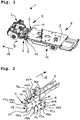
- Fig. 1 is a motorhome shown schematically 1.
- a motorhome shown schematically 1.
- FIG. 1 For reasons of simplified illustration, further details of a residential structure or of a driver's cabin are not shown in greater detail here.
- the motorhome 1 comprises a motorized traction head 2 and an attachment chassis 3.
- the traction head 2 comprises viewed in the forward direction 18 on a right side 4 of a rear end 5 a first head support 6 and on a left side 7 of a rear end 5 a second Head support 8.
- the attachment chassis 3 comprises on a right side 9 of a front End 10 a first side member 11 and on a left side 12 of a front end 10, a second side member 13th
- first longitudinal member 11 of the cultivation chassis can be connected to the first head carrier 6 of the pulling head by means of a positive connection 14.
- the invention analogously also provides that the second longitudinal member of the cultivation chassis is connectable to the second head carrier of the pulling head by means of a positive connection.
- connection 14 comprises a plate-shaped holding means 15, wherein the holding means 15 is positively connected to the first side member 11 of the Anbauchassis and with the first head support 6 and fixable by means of fastening means (not shown).
- the holding means 15 recesses 19 to 19e, which form-fitting manner with recesses 16 to 16e on the side member 11 and with recesses 17 to 17e (17c, 17d, 17e are concealed by the side member 11) cooperate.
- the holding means 15 allows a motorhome (see Fig. 1 ) can be provided, in which longitudinal beams of the cultivation chassis can be connected stress-free with head straps of the pulling head.
Landscapes
- Engineering & Computer Science (AREA)
- Chemical & Material Sciences (AREA)
- Combustion & Propulsion (AREA)
- Transportation (AREA)
- Mechanical Engineering (AREA)
- Body Structure For Vehicles (AREA)
Abstract
Description
- Die Erfindung betrifft ein Reisemobil nach dem Oberbegriff des Anspruchs 1 sowie ein Verfahren zur Verbindung eines Zugkopfes mit einem Anbauchassis nach Anspruch 7.
- Aus dem Stand der Technik sind bereits zahlreiche Ausführungsformen von Reisemobilen bekannt. Hierzu ist u.a. auch der Nachteil bekannt, dass die Fertigung solcher Reisemobile mit geringer Flexibilität möglich ist, da die Komponenten Zugkopf und Anbauchassis einerseits bereits fertig montiert beziehbar sind und von diesem ausgehend ein Wohnaufbau erfolgen muss.
- Andererseits ist es beispielsweise bei als so genannten Sandwich-Konstruktionen ausgestalteten Anbauchassis bzw. Längsträgern des Anbauchassis nicht möglich, diese zu einem gewünschten bzw. definierten Fertigungsgrad vorzumontieren und das vorgefertigte Anbauchassis sodann mit dem Zugkopf bzw. mit entsprechenden Kopfträgern zu verbinden. Dies begründet sich z.B. darin, dass das Anbauchassis bzw. die Längsträger des Anbauchassis zumindest kurzzeitig entsprechend unter entsprechender Spannung aufgeweitet werden müssten, um diese sodann mit Kopfträgern verbinden zu können.
- Aufgrund mangelnder Stabilität beispielsweise bei Sandwich-Konstruktionen sind derartige Aufweitungen von Längsträgern des Anbauchassis jedoch zumindest spannungsfrei bzw. zerstörungsfrei nicht durchführbar.
- Aufgabe der Erfindung ist es, die genannten Nachteile zu beseitigen und ein Reisemobil bereitzustellen, welches eine stabile Verbindung der Kopfträger des Zugkopfes mit Längsträgern des Anbauchassis aufweist, wobei diese Verbindung besonders einfach bereitgestellt werden kann. Es ist weiterhin Aufgabe der Erfindung, ein Verfahren zur Verbindung eines Zugkopfes mit einem Anbauchassis bereitzustellen, wobei auch sichergestellt werden kann, dass das Anbauchassis zu einem gewünschten bzw. definierten Grad vorgefertigt werden kann und erst im Anschluss mit dem Zugkopf verbunden werden kann.
- Zur Lösung der Aufgabe wird ein Reisemobil oder dergleichen Freizeitfahrzeug vorgeschlagen, umfassend einen motorisierten Zugkopf und ein Anbauchassis, wobei der Zugkopf in Vorwärts- bzw. Fahrtrichtung betrachtet an einer rechten Seite eines hinteren Endes einen ersten Kopfträger und an einer linken Seite eines hinteren Endes einen zweiten Kopfträger umfasst und wobei das Anbauchassis an einer rechten Seite eines vorderen Endes einen ersten Längsträger und an einer linken Seite eines vorderen Endes einen zweiten Längsträger umfasst, wobei der erste Längsträger des Anbauchassis mit dem ersten Kopfträger des Zugkopfes mittels wenigstens einer formschlüssigen Verbindung verbindbar ist und wobei der zweite Längsträger des Anbauchassis mit dem zweiten Kopfträger des Zugkopfes mittels wenigstens einer formschlüssigen Verbindung verbindbar ist.
- Erfindungsgemäß ist vorgesehen, dass die wenigstens eine Verbindung zumindest ein plattenförmiges Haltemittel umfasst, welches formschlüssig mit dem ersten Längsträger des Anbauchassis und/oder mit dem zweiten Längsträger des Anbauchassis oder mit dem ersten Kopfträger des Zugkopfes und/oder mit dem zweiten Kopfträger des Zugkopfes verbindbar und mittels Befestigungsmitteln fixierbar ist.
- Das plattenförmige Haltemittel ermöglicht, dass Längsträger des Anbauchassis und Längsträger des Zugkopfes mittels Befestigungsmitteln stabil und besonders einfach verbunden werden können. Weiterhin wird ermöglicht, dass Kopfträger und Längsträger einfach und insbesondere ohne Aufweitung der Längsträger, d.h. zerstörungsfrei miteinander verbunden werden können. Somit kann ermöglicht werden, dass das Anbauchassis zu einem gewünschten bzw. definierten Grad vorgefertigt wird und erst im Anschluss daran mit dem Zugkopf bzw. mit Kopfträgern verbunden wird. Dies kann auch so aufgefasst werden, dass Zugkopf und Anbauchassis spannungsfrei miteinander verbindbar sind bzw. verbunden werden.
- In einer besonders vorteilhaften Ausgestaltung der Erfindung kann vorgesehen sein, dass das Haltemittel und das Befestigungsmittel einstückig ausgebildet sind. Dadurch kann der Montageaufwand bei der Verbindung von Anbauchassis mit Zugkopfes weiter verringert werden.
- In einer weiteren besonders vorteilhaften Ausgestaltung der Erfindung kann vorgesehen sein, dass das Haltemittel Ausnehmungen umfasst, welche in Ausnehmungen am ersten Kopfträger des Zugkopfes und/oder am zweiten Kopfträger des Zugkopfes und/oder am ersten Längsträger des Anbauchassis und/oder am zweiten Längsträger des Anbauchassis formschlüssig eingreifbar sind. Derartige Ausnehmungen können einerseits durch deren Anordnung bzw. Orientierungen den Montageaufwand vereinfachen und andererseits die Stabilität der Verbindung von Zugkopf und Anbauchassis erhöhen.
- Um Stabilitäten der Verbindungen von Längsträger und Kopfträger weiter zu erhöhen, kann in einer besonders bevorzugten Weiterbildung der Erfindung vorgesehen sein, dass das Haltemittel Schernocken umfasst.
- Um zumindest eine ausreichende Befestigung von Kopfträger und Längsträger zu ermöglichen, kann die Erfindung in einer vorteilhaften Ausgestaltung vorsehen, dass das Haltemittel mittels Schraubverbindungen und/oder Nietverbindungen mit dem ersten Längsträger des Anbauchassis und/oder mit dem zweiten Längsträger des Anbauchassis und/oder mit dem ersten Kopfträger des Zugkopfes und/oder mit dem zweiten Kopfträger des Zugkopfes verbindbar ist. Lösbare Schraubverbindungen können einen etwaigen Reparaturaufwand senken. Nietverbindungen hingegen können eine dauerhafte und insbesondere auch eine erhöhte Stabilität der Verbindung von Zugkopf und Anbauchassis ermöglichen.
- Eine vorteilhafte Weiterentwicklung der Erfindung kann vorsehen, dass das Haltemittel und die Kopfträger des Zugkopfes jeweils Ausnehmungen umfassen, wobei die Ausnehmungen des Haltemittels und die Ausnehmungen der Kopfträger des Zugkopfes gleiche Tiefen aufweisen. Hierdurch können abgleitende Bewegungen von Haltemittel und Kopfträger vermieden werden. Zudem berühren sich die Grundflächen der Ausnehmungen auf diese Weise nicht, da durch die Materialstärke des Längsträgers ein Abstand gegeben ist. Die Positionierung und Arretierung erfolgt insbesondere über die Kegelflächen in den Ausnehmungen. Somit kann die Verbindung von Haltemittel und Kopfträger bzw. von Längsträger und Kopfträger weiter stabilisiert werden.
- Die Erfindung betrifft auch ein Verfahren zur Verbindung eines Zugkopfes mit einem Anbauchassis, insbesondere Fertigung eines Reisemobils oder dergleichen Freizeitfahrzeugs, welches durch die folgenden Schritte gekennzeichnet ist:
- 1) Bereitstellen eines Anbauchassis, wobei das Anbauchassis an einer rechten Seite eines vorderen Endes einen ersten Längsträger und an einer linken Seite eines vorderen Endes einen zweiten Längsträger umfasst und Bereitstellen eines Zugkopfes, wobei der Zugkopf an einer rechten Seite eines hinteren Endes einen ersten Kopfträger und an einer linken Seite eines hinteren Endes einen zweiten Kopfträger umfasst;
- 2) Verbinden der Längsträger des Anbauchassis mit den Kopfträgern des Zugkopfes mittels je wenigstens eines plattenförmigen Haltemittels und Befestigungsmitteln.
- Um die Stabilität der Verbindung von Anbauchassis und Zugkopf zu erhöhen, kann in einer Weiterbildung der Erfindung vorgesehen sein, dass die Längsträger des Anbauchassis auf die Kopfträger des Zugkopfes aufgeschoben werden und befestigt, insbesondere verriegelt werden oder dass die Kopfträger des Zugkopfes auf die Längsträger des Anbauchassis aufgeschoben und befestigt, insbesondere verriegelt werden.
- In einer besonders vorteilhaften Weiterbildung der Erfindung kann auch vorgesehen sein, dass das Aufschieben spannungsfrei erfolgt.
- Ein spannungsfreies Aufschieben ist im Sinne der Erfindung insbesondere so aufzufassen, dass Längsträger des Anbauchassis nicht aufgeweitet werden, um mit Kopfträgern verbunden zu werden. Dies kann ermöglichen, dass auch Anbauchassis mit geringerer Stabilität, z.B. Sandwich-Konstruktionen, stabil und überdies zerstörungsfrei mit Zugköpfen verbunden werden können bzw. verbindbar sind.
- Eine weitere vorteilhafte Weiterbildung der Erfindung kann vorsehen, dass das Anbauchassis als Sandwich-Konstruktion ausgebildet wird, welches wenigstens einen Doppelboden umfasst. Derartige Sandwich-Konstruktionen ermöglichen Gewichtseinsparungen sowie erhöhte Stauraumnutzungen.
- Um ein Anbauchassis mit erhöhter Stabilität und Tragkraft bereitstellen zu können, kann in einer weiteren vorteilhaften Weiterbildung der Erfindung vorsehen sein, dass das Anbauchassis ein Stahlgerippe umfasst.
- Nachfolgend wird die Erfindung anhand von Zeichnungen näher erläutert. Hierbei zeigt:
- Fig. 1:
- eine stark vereinfachte schematische Darstellung eines erfindungsgemäßen Reisemobils;
- Fig. 2:
- einen Ausschnitt aus dem in
Fig. 1 gezeigten Reisemobils in einer Explosionsdarstellung. - In der
Fig. 1 ist ein Reisemobil schematisch 1 dargestellt. Aus Gründen vereinfachter Darstellung sind hierbei weitere Details zu einem Wohnaufbau bzw. zu einer Fahrerkabine nicht näher gezeigt. - Das Reisemobil 1 umfasst einen motorisierten Zugkopf 2 und ein Anbauchassis 3. Der Zugkopf 2 umfasst in Vorwärts- bzw. Fahrtrichtung 18 betrachtet an einer rechten Seite 4 eines hinteren Endes 5 einen ersten Kopfträger 6 und an einer linken Seite 7 eines hinteren Endes 5 einen zweiten Kopfträger 8. Das Anbauchassis 3 umfasst an einer rechten Seite 9 eines vorderen Endes 10 einen ersten Längsträger 11 und an einer linken Seite 12 eines vorderen Endes 10 einen zweiten Längsträger 13.
- Es ist aus der
Fig. 2 ersichtlich, dass der erste Längsträger 11 des Anbauchassis mit dem ersten Kopfträger 6 des Zugkopfes mittels einer formschlüssigen Verbindung 14 verbindbar ist. - Ohne weitere Darstellung sieht die Erfindung in Analogie hierzu auch vor, dass der zweite Längsträger des Anbauchassis mit dem zweiten Kopfträger des Zugkopfes mittels einer formschlüssigen Verbindung verbindbar ist.
- Im Kern sieht die Erfindung wie in der
Fig. 2 gezeigt vor, dass die Verbindung 14 ein plattenförmiges Haltemittel 15 umfasst, wobei das Haltemittel 15 formschlüssig mit dem ersten Längsträger 11 des Anbauchassis und mit dem ersten Kopfträger 6 verbindbar und mittels Befestigungsmitteln (nicht gezeigt) fixierbar ist. Zur Herstellung dieser formschlüssigen Verbindung umfasst das Haltemittel 15 Ausnehmungen 19 bis 19e, welche formschlüssig mit Ausnehmungen 16 bis 16e am Längsträger 11 bzw. mit Ausnehmungen 17 bis 17e (17c, 17d, 17e sind hierbei verdeckt vom Längsträger 11) zusammenwirken. - Das Haltemittel 15 ermöglicht, dass ein Reisemobil (siehe
Fig. 1 ) bereitgestellt werden kann, bei welchem Längsträger des Anbauchassis spannungsfrei mit Kopfträgern des Zugkopfes verbunden werden können. -
- 1
- Reisemobil oder dergleichen Freizeitfahrzeug
- 2
- Zugkopf
- 3
- Anbauchassis
- 4
- rechte Seite
- 5
- hinteres Ende (des Zugkopfes)
- 6
- erster Kopfträger
- 7
- linke Seite
- 8
- zweiter Kopfträger
- 9
- rechte Seite
- 10
- vorderes Ende (des Anbauchassis)
- 11
- erster Längsträger
- 12
- linke Seite
- 13
- zweiter Längsträger
- 14
- Verbindung
- 15
- Haltemittel
- 16
- Ausnehmung (am vorderen Ende 10)
- 16a
- Ausnehmung (am vorderen Ende 10)
- 16b
- Ausnehmung (am vorderen Ende 10)
- 16c
- Ausnehmung (am vorderen Ende 10)
- 16d
- Ausnehmung (am vorderen Ende 10)
- 16e
- Ausnehmung (am vorderen Ende 10)
- 17
- Ausnehmung (des ersten Kopfträgers)
- 17a
- Ausnehmung (des ersten Kopfträgers)
- 17b
- Ausnehmung (des ersten Kopfträgers)
- 17c
- Ausnehmung (des ersten Kopfträgers)
- 17d
- Ausnehmung (des ersten Kopfträgers)
- 17e
- Ausnehmung (des ersten Kopfträgers)
- 18
- Vorwärts- bzw. Fahrtrichtung
- 19
- Ausnehmung (des Haltemittels)
- 19a
- Ausnehmung (des Haltemittels)
- 19b
- Ausnehmung (des Haltemittels)
- 19c
- Ausnehmung (des Haltemittels)
- 19d
- Ausnehmung (des Haltemittels)
- 19e
- Ausnehmung (des Haltemittels)
Claims (11)
- Reisemobil oder dergleichen Freizeitfahrzeug (1), umfassend einen motorisierten Zugkopf (2) und ein Anbauchassis (3),- wobei der Zugkopf (2) in Vorwärts- bzw. Fahrtrichtung (18) betrachtet an einer rechten Seite (4) eines hinteren Endes (5) einen ersten Kopfträger (6) und an einer linken Seite (7) eines hinteren Endes (5) einen zweiten Kopfträger (8) umfasst und- wobei das Anbauchassis (3) an einer rechten Seite (9) eines vorderen Endes (10) einen ersten Längsträger (11) und an einer linken Seite (12) eines vorderen Endes (10) einen zweiten Längsträger (13) umfasst,- wobei der erste Längsträger (11) des Anbauchassis (3) mit dem ersten Kopfträger (6) des Zugkopfes (2) mittels wenigstens einer formschlüssigen Verbindung (14) verbindbar ist und- wobei der zweite Längsträger (13) des Anbauchassis (3) mit dem zweiten Kopfträger (8) des Zugkopfes (2) mittels wenigstens einer formschlüssigen Verbindung (14) verbindbar ist,dadurch gekennzeichnet, dass- die wenigstens eine Verbindung (14) zumindest ein plattenförmiges Haltemittel (15) umfasst, welches formschlüssig mit dem ersten Längsträger (11) des Anbauchassis (3) und/oder mit dem zweiten Längsträger (13) des Anbauchassis (3) oder mit dem ersten Kopfträger (6) des Zugkopfes (2) und/oder mit dem zweiten Kopfträger (8) des Zugkopfes (2) verbindbar und mittels Befestigungsmitteln fixierbar ist.
- Reisemobil nach Anspruch 1, dadurch gekennzeichnet, dass das Haltemittel (15) und das Befestigungsmittel einstückig ausgebildet sind.
- Reisemobil nach einem der vorangehenden Ansprüche, dadurch gekennzeichnet, dass das Haltemittel (15) Ausnehmungen (19, 19a, 19b, 19c, 19d, 19e) umfasst, welche in Ausnehmungen (16, 16a, 16b, 16c; 16d, 16e; 17, 17a, 17b, 17c, 17d, 17e) am ersten Kopfträger (6) des Zugkopfes (2) und/oder am zweiten Kopfträger (8) des Zugkopfes (2) und/oder am ersten Längsträger (11) des Anbauchassis (3) und/oder am zweiten Längsträger (13) des Anbauchassis (3) formschlüssig eingreifbar sind.
- Reisemobil nach einem der vorangehenden Ansprüche, dadurch gekennzeichnet, dass das Haltemittel (15) Schernocken umfasst.
- Reisemobil nach einem der vorangehenden Ansprüche, dadurch gekennzeichnet, dass das Haltemittel (15) mittels Schraubverbindungen und/oder Nietverbindungen mit dem ersten Längsträger (11) des Anbauchassis (3) und/oder mit dem zweiten Längsträger (13) des Anbauchassis (3) und/oder mit dem ersten Kopfträger (6) des Zugkopfes (2) und/oder mit dem zweiten Kopfträger (8) des Zugkopfes (2) verbindbar ist.
- Reisemobil nach einem der vorangehenden Ansprüche, dadurch gekennzeichnet, dass das Haltemittel (15) und die Kopfträger (6, 8) des Zugkopfes (2) jeweils Ausnehmungen umfassen, wobei die Ausnehmungen (19, 19a, 19b, 19c, 19d, 19e) des Haltemittels (15) und die Ausnehmungen (17, 17a, 17b, 17c, 17d, 17e) der Kopfträger (6, 8) des Zugkopfes (2) gleiche Tiefen aufweisen.
- Verfahren zur Verbindung eines Zugkopfes (2) mit einem Anbauchassis (3), insbesondere Fertigung eines Reisemobils oder dergleichen Freizeitfahrzeugs, gekennzeichnet durch folgende Schritte:1) Bereitstellen eines Anbauchassis (3), wobei das Anbauchassis (3) an einer rechten Seite (9) eines vorderen Endes (10) einen ersten Längsträger (11) und an einer linken Seite (12) eines vorderen Endes (10) einen zweiten Längsträger (13) umfasst und Bereitstellen eines Zugkopfes (2), wobei der Zugkopf (2) an einer rechten Seite (4) eines hinteren Endes (5) einen ersten Kopfträger (6) und an einer linken Seite (7) eines hinteren Endes (5) einen zweiten Kopfträger (8) umfasst;2) Verbinden der Längsträger (11, 13) des Anbauchassis (3) mit den Kopfträgern (6, 8) des Zugkopfes (2) mittels je wenigstens eines plattenförmigen Haltemittels (15) und Befestigungsmitteln.
- Verfahren nach Anspruch 7, dadurch gekennzeichnet, dass die Längsträger (11, 13) des Anbauchassis (3) auf die Kopfträger (6, 8) des Zugkopfes (2) aufgeschoben werden und befestigt, insbesondere verriegelt werden oder dass die Kopfträger (6, 8) des Zugkopfes (2) auf die Längsträger (11, 13) des Anbauchassis (3) aufgeschoben und befestigt, insbesondere verriegelt werden.
- Verfahren nach Anspruch 8, dadurch gekennzeichnet, dass das Aufschieben spannungsfrei erfolgt.
- Verfahren nach Anspruch 7, dadurch gekennzeichnet, dass das Anbauchassis (3) als Sandwich-Konstruktion ausgebildet wird, welches wenigstens einen Doppelboden umfasst.
- Verfahren nach Anspruch 7, dadurch gekennzeichnet, dass das Anbauchassis (3) ein Stahlgerippe umfasst.
Priority Applications (1)
| Application Number | Priority Date | Filing Date | Title |
|---|---|---|---|
| SI201831088T SI3424802T1 (sl) | 2017-07-03 | 2018-06-07 | Avtodom |
Applications Claiming Priority (1)
| Application Number | Priority Date | Filing Date | Title |
|---|---|---|---|
| DE102017114815.9A DE102017114815A1 (de) | 2017-07-03 | 2017-07-03 | Reisemobil |
Publications (2)
| Publication Number | Publication Date |
|---|---|
| EP3424802A1 true EP3424802A1 (de) | 2019-01-09 |
| EP3424802B1 EP3424802B1 (de) | 2024-01-31 |
Family
ID=62712748
Family Applications (1)
| Application Number | Title | Priority Date | Filing Date |
|---|---|---|---|
| EP18176553.8A Active EP3424802B1 (de) | 2017-07-03 | 2018-06-07 | Reisemobil |
Country Status (4)
| Country | Link |
|---|---|
| EP (1) | EP3424802B1 (de) |
| DE (1) | DE102017114815A1 (de) |
| PL (1) | PL3424802T3 (de) |
| SI (1) | SI3424802T1 (de) |
Cited By (2)
| Publication number | Priority date | Publication date | Assignee | Title |
|---|---|---|---|---|
| CN110510006A (zh) * | 2019-08-29 | 2019-11-29 | 陕西重型汽车有限公司 | 一种承载式车辆分段式连接结构 |
| EP3785966A1 (de) * | 2019-08-29 | 2021-03-03 | Scolotech GmbH | Reisefahrzeugvorrichtung |
Citations (7)
| Publication number | Priority date | Publication date | Assignee | Title |
|---|---|---|---|---|
| DE2930036A1 (de) * | 1979-07-24 | 1981-02-19 | Kober Kg A | Fahrgestell fuer einen selbstfahrenden wohnwagen (wohnmobil) |
| CH686945A5 (de) * | 1993-01-14 | 1996-08-15 | Marcel Baldinger | Vorrichtung zum Verbinden eines Fahrzeugaufbau-Traegers mit einem Chassis-Tragbalken eines Nutzfahrzeuges. |
| WO2000037301A1 (de) * | 1998-12-18 | 2000-06-29 | Al-Ko Kober Ag | Chassis für ein frontgetriebenes kraftfahrzeug |
| DE202005009101U1 (de) * | 2004-09-13 | 2006-02-02 | Al-Ko Kober Ag | Adapter für Zugköpfe und Anbauchassis |
| EP2334539A1 (de) * | 2008-09-12 | 2011-06-22 | Volvo Group North America, LLC | Strukturverbindung für einen nutzfahrzeugrahmen und mit einer strukturverbindung hergestellter rahmen |
| EP2738068A1 (de) * | 2012-11-30 | 2014-06-04 | Hymer AG | Straßenfahrzeugchassis und Straßenfahrzeug |
| WO2016134281A1 (en) * | 2015-02-20 | 2016-08-25 | Champion Bus, Inc. | Low-floor drop frame for passenger transport vehicle |
-
2017
- 2017-07-03 DE DE102017114815.9A patent/DE102017114815A1/de not_active Withdrawn
-
2018
- 2018-06-07 PL PL18176553.8T patent/PL3424802T3/pl unknown
- 2018-06-07 EP EP18176553.8A patent/EP3424802B1/de active Active
- 2018-06-07 SI SI201831088T patent/SI3424802T1/sl unknown
Patent Citations (7)
| Publication number | Priority date | Publication date | Assignee | Title |
|---|---|---|---|---|
| DE2930036A1 (de) * | 1979-07-24 | 1981-02-19 | Kober Kg A | Fahrgestell fuer einen selbstfahrenden wohnwagen (wohnmobil) |
| CH686945A5 (de) * | 1993-01-14 | 1996-08-15 | Marcel Baldinger | Vorrichtung zum Verbinden eines Fahrzeugaufbau-Traegers mit einem Chassis-Tragbalken eines Nutzfahrzeuges. |
| WO2000037301A1 (de) * | 1998-12-18 | 2000-06-29 | Al-Ko Kober Ag | Chassis für ein frontgetriebenes kraftfahrzeug |
| DE202005009101U1 (de) * | 2004-09-13 | 2006-02-02 | Al-Ko Kober Ag | Adapter für Zugköpfe und Anbauchassis |
| EP2334539A1 (de) * | 2008-09-12 | 2011-06-22 | Volvo Group North America, LLC | Strukturverbindung für einen nutzfahrzeugrahmen und mit einer strukturverbindung hergestellter rahmen |
| EP2738068A1 (de) * | 2012-11-30 | 2014-06-04 | Hymer AG | Straßenfahrzeugchassis und Straßenfahrzeug |
| WO2016134281A1 (en) * | 2015-02-20 | 2016-08-25 | Champion Bus, Inc. | Low-floor drop frame for passenger transport vehicle |
Cited By (3)
| Publication number | Priority date | Publication date | Assignee | Title |
|---|---|---|---|---|
| CN110510006A (zh) * | 2019-08-29 | 2019-11-29 | 陕西重型汽车有限公司 | 一种承载式车辆分段式连接结构 |
| EP3785966A1 (de) * | 2019-08-29 | 2021-03-03 | Scolotech GmbH | Reisefahrzeugvorrichtung |
| CN110510006B (zh) * | 2019-08-29 | 2021-05-04 | 陕西重型汽车有限公司 | 一种承载式车辆分段式连接结构 |
Also Published As
| Publication number | Publication date |
|---|---|
| EP3424802B1 (de) | 2024-01-31 |
| DE102017114815A1 (de) | 2019-01-03 |
| PL3424802T3 (pl) | 2024-07-01 |
| SI3424802T1 (sl) | 2024-05-31 |
Similar Documents
| Publication | Publication Date | Title |
|---|---|---|
| EP2734414B1 (de) | Ladeschiene sowie gleitstein für eine ladeschiene | |
| DE602005000493T2 (de) | Flugzeugdeck | |
| EP3484744A1 (de) | Längseinsteller sowie fahrzeugsitz | |
| EP3274213B1 (de) | Adapteranordung für einen fahrzeugsitz und fahrzeugsitz | |
| WO2009013133A2 (de) | Profil mit wenigstens einem hohlprofilabschnitt | |
| EP2508407A1 (de) | Gerüst, insbesondere für elektrische Einrichtungen in einem Schienenfahrzeug, und Verfahren zur Herstellung des Gerüsts | |
| EP3424802B1 (de) | Reisemobil | |
| EP2945828B1 (de) | Montagevorrichtung für ein seitenwandverkleidungselement eines schienenfahrzeugs | |
| DE102006052281B4 (de) | Abstützelement für einen Cockpitträger | |
| EP2626272A1 (de) | Befestigungsvorrichtung mit Steckelement für eine Gepäckablage, sowie Gepäckablage für einen Schienenfahrzeugwagen | |
| EP0770540B1 (de) | Kraftfahrzeug mit umklappbaren Sitzlehnen | |
| EP2700554A1 (de) | Vorrichtung zur freitragenden Befestigung eines Fahrgastsitzes und Verfahren zur Herstellung einer solchen Vorrichtung sowie Wagenkasten | |
| DE102014226522B4 (de) | Montagelehre zur Anordnung von Zierteilen an einem Kraftfahrzeug | |
| EP2945827B1 (de) | Montagevorrichtung für ein seitenwandverkleidungselement eines schienenfahrzeugs | |
| DE102012009428A1 (de) | Lagerungselement für eine Rückenlehne einer Sitzanlage eines Kraftwagens | |
| EP3756940A1 (de) | Fahrzeug | |
| DE20201327U1 (de) | Vorrichtung zum Verankern eines Sitzes an einem Fahrzeugboden | |
| DE102014007165A1 (de) | Sitzquerträger für eine Personenkraftwagenkarosserie | |
| DE102006030932B4 (de) | Fahrgastsitz | |
| EP4275995A1 (de) | Kraftfahrzeug-dachkonstruktion mit mehreren dach-querträgern und einer dachverkleidung sowie montageverfahren | |
| DE102013108049B4 (de) | KFZ-Außenrückblickspiegelmodul und KFZ-Außenrückblickspiegel | |
| EP4088958A1 (de) | Versteifungsstruktur für ein aufstelldach eines freizeitfahrzeugs sowie freizeitfahrzeug mit einer solchen versteifungsstruktur | |
| DE102016103948A1 (de) | Vorrichtung zum Führen einer verschiebbaren Fensterscheibe sowie Verfahren zur Herstellung einer solchen Vorrichtung | |
| DE102010052454B4 (de) | Halteteil für den Haltegriff in einem Kraftfahrzeug und Haltegriffanordnung in einem Kraftfahrzeug | |
| DE10343744B4 (de) | Befestigungsanordnung zwischen einem Befestigungsteil und einem Karosseriebauteil eines Kraftfahrzeugs |
Legal Events
| Date | Code | Title | Description |
|---|---|---|---|
| PUAI | Public reference made under article 153(3) epc to a published international application that has entered the european phase |
Free format text: ORIGINAL CODE: 0009012 |
|
| STAA | Information on the status of an ep patent application or granted ep patent |
Free format text: STATUS: THE APPLICATION HAS BEEN PUBLISHED |
|
| AK | Designated contracting states |
Kind code of ref document: A1 Designated state(s): AL AT BE BG CH CY CZ DE DK EE ES FI FR GB GR HR HU IE IS IT LI LT LU LV MC MK MT NL NO PL PT RO RS SE SI SK SM TR |
|
| AX | Request for extension of the european patent |
Extension state: BA ME |
|
| STAA | Information on the status of an ep patent application or granted ep patent |
Free format text: STATUS: REQUEST FOR EXAMINATION WAS MADE |
|
| 17P | Request for examination filed |
Effective date: 20190628 |
|
| RBV | Designated contracting states (corrected) |
Designated state(s): AL AT BE BG CH CY CZ DE DK EE ES FI FR GB GR HR HU IE IS IT LI LT LU LV MC MK MT NL NO PL PT RO RS SE SI SK SM TR |
|
| STAA | Information on the status of an ep patent application or granted ep patent |
Free format text: STATUS: EXAMINATION IS IN PROGRESS |
|
| 17Q | First examination report despatched |
Effective date: 20200508 |
|
| GRAP | Despatch of communication of intention to grant a patent |
Free format text: ORIGINAL CODE: EPIDOSNIGR1 |
|
| STAA | Information on the status of an ep patent application or granted ep patent |
Free format text: STATUS: GRANT OF PATENT IS INTENDED |
|
| INTG | Intention to grant announced |
Effective date: 20230908 |
|
| GRAS | Grant fee paid |
Free format text: ORIGINAL CODE: EPIDOSNIGR3 |
|
| GRAA | (expected) grant |
Free format text: ORIGINAL CODE: 0009210 |
|
| STAA | Information on the status of an ep patent application or granted ep patent |
Free format text: STATUS: THE PATENT HAS BEEN GRANTED |
|
| AK | Designated contracting states |
Kind code of ref document: B1 Designated state(s): AL AT BE BG CH CY CZ DE DK EE ES FI FR GB GR HR HU IE IS IT LI LT LU LV MC MK MT NL NO PL PT RO RS SE SI SK SM TR |
|
| REG | Reference to a national code |
Ref country code: GB Ref legal event code: FG4D Free format text: NOT ENGLISH Ref country code: CH Ref legal event code: EP |
|
| REG | Reference to a national code |
Ref country code: DE Ref legal event code: R096 Ref document number: 502018014057 Country of ref document: DE |
|
| REG | Reference to a national code |
Ref country code: IE Ref legal event code: FG4D Free format text: LANGUAGE OF EP DOCUMENT: GERMAN |
|
| P01 | Opt-out of the competence of the unified patent court (upc) registered |
Effective date: 20240408 |
|
| REG | Reference to a national code |
Ref country code: LT Ref legal event code: MG9D |
|
| REG | Reference to a national code |
Ref country code: NL Ref legal event code: MP Effective date: 20240131 |
|
| PG25 | Lapsed in a contracting state [announced via postgrant information from national office to epo] |
Ref country code: IS Free format text: LAPSE BECAUSE OF FAILURE TO SUBMIT A TRANSLATION OF THE DESCRIPTION OR TO PAY THE FEE WITHIN THE PRESCRIBED TIME-LIMIT Effective date: 20240531 |
|
| PG25 | Lapsed in a contracting state [announced via postgrant information from national office to epo] |
Ref country code: LT Free format text: LAPSE BECAUSE OF FAILURE TO SUBMIT A TRANSLATION OF THE DESCRIPTION OR TO PAY THE FEE WITHIN THE PRESCRIBED TIME-LIMIT Effective date: 20240131 |
|
| PG25 | Lapsed in a contracting state [announced via postgrant information from national office to epo] |
Ref country code: GR Free format text: LAPSE BECAUSE OF FAILURE TO SUBMIT A TRANSLATION OF THE DESCRIPTION OR TO PAY THE FEE WITHIN THE PRESCRIBED TIME-LIMIT Effective date: 20240501 |
|
| PG25 | Lapsed in a contracting state [announced via postgrant information from national office to epo] |
Ref country code: HR Free format text: LAPSE BECAUSE OF FAILURE TO SUBMIT A TRANSLATION OF THE DESCRIPTION OR TO PAY THE FEE WITHIN THE PRESCRIBED TIME-LIMIT Effective date: 20240131 Ref country code: RS Free format text: LAPSE BECAUSE OF FAILURE TO SUBMIT A TRANSLATION OF THE DESCRIPTION OR TO PAY THE FEE WITHIN THE PRESCRIBED TIME-LIMIT Effective date: 20240430 Ref country code: NL Free format text: LAPSE BECAUSE OF FAILURE TO SUBMIT A TRANSLATION OF THE DESCRIPTION OR TO PAY THE FEE WITHIN THE PRESCRIBED TIME-LIMIT Effective date: 20240131 |
|
| PG25 | Lapsed in a contracting state [announced via postgrant information from national office to epo] |
Ref country code: ES Free format text: LAPSE BECAUSE OF FAILURE TO SUBMIT A TRANSLATION OF THE DESCRIPTION OR TO PAY THE FEE WITHIN THE PRESCRIBED TIME-LIMIT Effective date: 20240131 |
|
| PG25 | Lapsed in a contracting state [announced via postgrant information from national office to epo] |
Ref country code: RS Free format text: LAPSE BECAUSE OF FAILURE TO SUBMIT A TRANSLATION OF THE DESCRIPTION OR TO PAY THE FEE WITHIN THE PRESCRIBED TIME-LIMIT Effective date: 20240430 Ref country code: NO Free format text: LAPSE BECAUSE OF FAILURE TO SUBMIT A TRANSLATION OF THE DESCRIPTION OR TO PAY THE FEE WITHIN THE PRESCRIBED TIME-LIMIT Effective date: 20240430 Ref country code: NL Free format text: LAPSE BECAUSE OF FAILURE TO SUBMIT A TRANSLATION OF THE DESCRIPTION OR TO PAY THE FEE WITHIN THE PRESCRIBED TIME-LIMIT Effective date: 20240131 Ref country code: LT Free format text: LAPSE BECAUSE OF FAILURE TO SUBMIT A TRANSLATION OF THE DESCRIPTION OR TO PAY THE FEE WITHIN THE PRESCRIBED TIME-LIMIT Effective date: 20240131 Ref country code: IS Free format text: LAPSE BECAUSE OF FAILURE TO SUBMIT A TRANSLATION OF THE DESCRIPTION OR TO PAY THE FEE WITHIN THE PRESCRIBED TIME-LIMIT Effective date: 20240531 Ref country code: HR Free format text: LAPSE BECAUSE OF FAILURE TO SUBMIT A TRANSLATION OF THE DESCRIPTION OR TO PAY THE FEE WITHIN THE PRESCRIBED TIME-LIMIT Effective date: 20240131 Ref country code: GR Free format text: LAPSE BECAUSE OF FAILURE TO SUBMIT A TRANSLATION OF THE DESCRIPTION OR TO PAY THE FEE WITHIN THE PRESCRIBED TIME-LIMIT Effective date: 20240501 Ref country code: FI Free format text: LAPSE BECAUSE OF FAILURE TO SUBMIT A TRANSLATION OF THE DESCRIPTION OR TO PAY THE FEE WITHIN THE PRESCRIBED TIME-LIMIT Effective date: 20240131 Ref country code: ES Free format text: LAPSE BECAUSE OF FAILURE TO SUBMIT A TRANSLATION OF THE DESCRIPTION OR TO PAY THE FEE WITHIN THE PRESCRIBED TIME-LIMIT Effective date: 20240131 Ref country code: BG Free format text: LAPSE BECAUSE OF FAILURE TO SUBMIT A TRANSLATION OF THE DESCRIPTION OR TO PAY THE FEE WITHIN THE PRESCRIBED TIME-LIMIT Effective date: 20240131 |
|
| PG25 | Lapsed in a contracting state [announced via postgrant information from national office to epo] |
Ref country code: PT Free format text: LAPSE BECAUSE OF FAILURE TO SUBMIT A TRANSLATION OF THE DESCRIPTION OR TO PAY THE FEE WITHIN THE PRESCRIBED TIME-LIMIT Effective date: 20240531 |
|
| PG25 | Lapsed in a contracting state [announced via postgrant information from national office to epo] |
Ref country code: SE Free format text: LAPSE BECAUSE OF FAILURE TO SUBMIT A TRANSLATION OF THE DESCRIPTION OR TO PAY THE FEE WITHIN THE PRESCRIBED TIME-LIMIT Effective date: 20240131 Ref country code: PT Free format text: LAPSE BECAUSE OF FAILURE TO SUBMIT A TRANSLATION OF THE DESCRIPTION OR TO PAY THE FEE WITHIN THE PRESCRIBED TIME-LIMIT Effective date: 20240531 Ref country code: LV Free format text: LAPSE BECAUSE OF FAILURE TO SUBMIT A TRANSLATION OF THE DESCRIPTION OR TO PAY THE FEE WITHIN THE PRESCRIBED TIME-LIMIT Effective date: 20240131 |
|
| PG25 | Lapsed in a contracting state [announced via postgrant information from national office to epo] |
Ref country code: DK Free format text: LAPSE BECAUSE OF FAILURE TO SUBMIT A TRANSLATION OF THE DESCRIPTION OR TO PAY THE FEE WITHIN THE PRESCRIBED TIME-LIMIT Effective date: 20240131 |
|
| PG25 | Lapsed in a contracting state [announced via postgrant information from national office to epo] |
Ref country code: SM Free format text: LAPSE BECAUSE OF FAILURE TO SUBMIT A TRANSLATION OF THE DESCRIPTION OR TO PAY THE FEE WITHIN THE PRESCRIBED TIME-LIMIT Effective date: 20240131 |
|
| PG25 | Lapsed in a contracting state [announced via postgrant information from national office to epo] |
Ref country code: EE Free format text: LAPSE BECAUSE OF FAILURE TO SUBMIT A TRANSLATION OF THE DESCRIPTION OR TO PAY THE FEE WITHIN THE PRESCRIBED TIME-LIMIT Effective date: 20240131 Ref country code: CZ Free format text: LAPSE BECAUSE OF FAILURE TO SUBMIT A TRANSLATION OF THE DESCRIPTION OR TO PAY THE FEE WITHIN THE PRESCRIBED TIME-LIMIT Effective date: 20240131 |
|
| PG25 | Lapsed in a contracting state [announced via postgrant information from national office to epo] |
Ref country code: SK Free format text: LAPSE BECAUSE OF FAILURE TO SUBMIT A TRANSLATION OF THE DESCRIPTION OR TO PAY THE FEE WITHIN THE PRESCRIBED TIME-LIMIT Effective date: 20240131 |
|
| PG25 | Lapsed in a contracting state [announced via postgrant information from national office to epo] |
Ref country code: SM Free format text: LAPSE BECAUSE OF FAILURE TO SUBMIT A TRANSLATION OF THE DESCRIPTION OR TO PAY THE FEE WITHIN THE PRESCRIBED TIME-LIMIT Effective date: 20240131 Ref country code: SK Free format text: LAPSE BECAUSE OF FAILURE TO SUBMIT A TRANSLATION OF THE DESCRIPTION OR TO PAY THE FEE WITHIN THE PRESCRIBED TIME-LIMIT Effective date: 20240131 Ref country code: RO Free format text: LAPSE BECAUSE OF FAILURE TO SUBMIT A TRANSLATION OF THE DESCRIPTION OR TO PAY THE FEE WITHIN THE PRESCRIBED TIME-LIMIT Effective date: 20240131 Ref country code: EE Free format text: LAPSE BECAUSE OF FAILURE TO SUBMIT A TRANSLATION OF THE DESCRIPTION OR TO PAY THE FEE WITHIN THE PRESCRIBED TIME-LIMIT Effective date: 20240131 Ref country code: DK Free format text: LAPSE BECAUSE OF FAILURE TO SUBMIT A TRANSLATION OF THE DESCRIPTION OR TO PAY THE FEE WITHIN THE PRESCRIBED TIME-LIMIT Effective date: 20240131 Ref country code: CZ Free format text: LAPSE BECAUSE OF FAILURE TO SUBMIT A TRANSLATION OF THE DESCRIPTION OR TO PAY THE FEE WITHIN THE PRESCRIBED TIME-LIMIT Effective date: 20240131 |
|
| REG | Reference to a national code |
Ref country code: DE Ref legal event code: R097 Ref document number: 502018014057 Country of ref document: DE |
|
| PLBE | No opposition filed within time limit |
Free format text: ORIGINAL CODE: 0009261 |
|
| STAA | Information on the status of an ep patent application or granted ep patent |
Free format text: STATUS: NO OPPOSITION FILED WITHIN TIME LIMIT |
|
| 26N | No opposition filed |
Effective date: 20241101 |
|
| PG25 | Lapsed in a contracting state [announced via postgrant information from national office to epo] |
Ref country code: MC Free format text: LAPSE BECAUSE OF FAILURE TO SUBMIT A TRANSLATION OF THE DESCRIPTION OR TO PAY THE FEE WITHIN THE PRESCRIBED TIME-LIMIT Effective date: 20240131 |
|
| REG | Reference to a national code |
Ref country code: CH Ref legal event code: PL |
|
| PG25 | Lapsed in a contracting state [announced via postgrant information from national office to epo] |
Ref country code: LU Free format text: LAPSE BECAUSE OF NON-PAYMENT OF DUE FEES Effective date: 20240607 |
|
| GBPC | Gb: european patent ceased through non-payment of renewal fee |
Effective date: 20240607 |
|
| PG25 | Lapsed in a contracting state [announced via postgrant information from national office to epo] |
Ref country code: IE Free format text: LAPSE BECAUSE OF NON-PAYMENT OF DUE FEES Effective date: 20240607 |
|
| PG25 | Lapsed in a contracting state [announced via postgrant information from national office to epo] |
Ref country code: CH Free format text: LAPSE BECAUSE OF NON-PAYMENT OF DUE FEES Effective date: 20240630 Ref country code: BE Free format text: LAPSE BECAUSE OF NON-PAYMENT OF DUE FEES Effective date: 20240630 |
|
| PG25 | Lapsed in a contracting state [announced via postgrant information from national office to epo] |
Ref country code: GB Free format text: LAPSE BECAUSE OF NON-PAYMENT OF DUE FEES Effective date: 20240607 |
|
| REG | Reference to a national code |
Ref country code: BE Ref legal event code: MM Effective date: 20240630 |
|
| PGFP | Annual fee paid to national office [announced via postgrant information from national office to epo] |
Ref country code: PL Payment date: 20250528 Year of fee payment: 8 |
|
| PGFP | Annual fee paid to national office [announced via postgrant information from national office to epo] |
Ref country code: FR Payment date: 20250624 Year of fee payment: 8 |
|
| PGFP | Annual fee paid to national office [announced via postgrant information from national office to epo] |
Ref country code: SI Payment date: 20250528 Year of fee payment: 8 |
|
| REG | Reference to a national code |
Ref country code: AT Ref legal event code: MM01 Ref document number: 1653700 Country of ref document: AT Kind code of ref document: T Effective date: 20240607 |
|
| PGFP | Annual fee paid to national office [announced via postgrant information from national office to epo] |
Ref country code: IT Payment date: 20250630 Year of fee payment: 8 |
|
| PG25 | Lapsed in a contracting state [announced via postgrant information from national office to epo] |
Ref country code: AT Free format text: LAPSE BECAUSE OF NON-PAYMENT OF DUE FEES Effective date: 20240607 |
|
| PG25 | Lapsed in a contracting state [announced via postgrant information from national office to epo] |
Ref country code: CY Free format text: LAPSE BECAUSE OF FAILURE TO SUBMIT A TRANSLATION OF THE DESCRIPTION OR TO PAY THE FEE WITHIN THE PRESCRIBED TIME-LIMIT; INVALID AB INITIO Effective date: 20180607 |
|
| PG25 | Lapsed in a contracting state [announced via postgrant information from national office to epo] |
Ref country code: HU Free format text: LAPSE BECAUSE OF FAILURE TO SUBMIT A TRANSLATION OF THE DESCRIPTION OR TO PAY THE FEE WITHIN THE PRESCRIBED TIME-LIMIT; INVALID AB INITIO Effective date: 20180607 |
|
| PG25 | Lapsed in a contracting state [announced via postgrant information from national office to epo] |
Ref country code: TR Free format text: LAPSE BECAUSE OF FAILURE TO SUBMIT A TRANSLATION OF THE DESCRIPTION OR TO PAY THE FEE WITHIN THE PRESCRIBED TIME-LIMIT Effective date: 20240131 |
|
| PGFP | Annual fee paid to national office [announced via postgrant information from national office to epo] |
Ref country code: DE Payment date: 20260317 Year of fee payment: 9 |