EP3425331A1 - Dispositif de traitement d'image et procédé de traitement d'image - Google Patents
Dispositif de traitement d'image et procédé de traitement d'image Download PDFInfo
- Publication number
- EP3425331A1 EP3425331A1 EP16880193.4A EP16880193A EP3425331A1 EP 3425331 A1 EP3425331 A1 EP 3425331A1 EP 16880193 A EP16880193 A EP 16880193A EP 3425331 A1 EP3425331 A1 EP 3425331A1
- Authority
- EP
- European Patent Office
- Prior art keywords
- distance information
- image
- images
- image processing
- amplitude
- Prior art date
- Legal status (The legal status is an assumption and is not a legal conclusion. Google has not performed a legal analysis and makes no representation as to the accuracy of the status listed.)
- Withdrawn
Links
Images


Classifications
-
- G—PHYSICS
- G01—MEASURING; TESTING
- G01C—MEASURING DISTANCES, LEVELS OR BEARINGS; SURVEYING; NAVIGATION; GYROSCOPIC INSTRUMENTS; PHOTOGRAMMETRY OR VIDEOGRAMMETRY
- G01C3/00—Measuring distances in line of sight; Optical rangefinders
- G01C3/02—Details
- G01C3/06—Use of electric means to obtain final indication
- G01C3/08—Use of electric radiation detectors
-
- G—PHYSICS
- G01—MEASURING; TESTING
- G01C—MEASURING DISTANCES, LEVELS OR BEARINGS; SURVEYING; NAVIGATION; GYROSCOPIC INSTRUMENTS; PHOTOGRAMMETRY OR VIDEOGRAMMETRY
- G01C3/00—Measuring distances in line of sight; Optical rangefinders
- G01C3/32—Measuring distances in line of sight; Optical rangefinders by focusing the object, e.g. on a ground glass screen
-
- G—PHYSICS
- G02—OPTICS
- G02B—OPTICAL ELEMENTS, SYSTEMS OR APPARATUS
- G02B7/00—Mountings, adjusting means, or light-tight connections, for optical elements
- G02B7/28—Systems for automatic generation of focusing signals
- G02B7/36—Systems for automatic generation of focusing signals using image sharpness techniques, e.g. image processing techniques for generating autofocus signals
- G02B7/365—Systems for automatic generation of focusing signals using image sharpness techniques, e.g. image processing techniques for generating autofocus signals by analysis of the spatial frequency components of the image
-
- G—PHYSICS
- G02—OPTICS
- G02B—OPTICAL ELEMENTS, SYSTEMS OR APPARATUS
- G02B7/00—Mountings, adjusting means, or light-tight connections, for optical elements
- G02B7/28—Systems for automatic generation of focusing signals
- G02B7/36—Systems for automatic generation of focusing signals using image sharpness techniques, e.g. image processing techniques for generating autofocus signals
- G02B7/38—Systems for automatic generation of focusing signals using image sharpness techniques, e.g. image processing techniques for generating autofocus signals measured at different points on the optical axis, e.g. focussing on two or more planes and comparing image data
-
- G—PHYSICS
- G06—COMPUTING OR CALCULATING; COUNTING
- G06T—IMAGE DATA PROCESSING OR GENERATION, IN GENERAL
- G06T7/00—Image analysis
- G06T7/50—Depth or shape recovery
- G06T7/55—Depth or shape recovery from multiple images
- G06T7/571—Depth or shape recovery from multiple images from focus
-
- H—ELECTRICITY
- H04—ELECTRIC COMMUNICATION TECHNIQUE
- H04N—PICTORIAL COMMUNICATION, e.g. TELEVISION
- H04N19/00—Methods or arrangements for coding, decoding, compressing or decompressing digital video signals
- H04N19/60—Methods or arrangements for coding, decoding, compressing or decompressing digital video signals using transform coding
- H04N19/62—Methods or arrangements for coding, decoding, compressing or decompressing digital video signals using transform coding by frequency transforming in three dimensions [3D]
-
- H—ELECTRICITY
- H04—ELECTRIC COMMUNICATION TECHNIQUE
- H04N—PICTORIAL COMMUNICATION, e.g. TELEVISION
- H04N23/00—Cameras or camera modules comprising electronic image sensors; Control thereof
- H04N23/80—Camera processing pipelines; Components thereof
-
- H—ELECTRICITY
- H04—ELECTRIC COMMUNICATION TECHNIQUE
- H04N—PICTORIAL COMMUNICATION, e.g. TELEVISION
- H04N23/00—Cameras or camera modules comprising electronic image sensors; Control thereof
- H04N23/95—Computational photography systems, e.g. light-field imaging systems
- H04N23/958—Computational photography systems, e.g. light-field imaging systems for extended depth of field imaging
- H04N23/959—Computational photography systems, e.g. light-field imaging systems for extended depth of field imaging by adjusting depth of field during image capture, e.g. maximising or setting range based on scene characteristics
-
- H—ELECTRICITY
- H04—ELECTRIC COMMUNICATION TECHNIQUE
- H04N—PICTORIAL COMMUNICATION, e.g. TELEVISION
- H04N1/00—Scanning, transmission or reproduction of documents or the like, e.g. facsimile transmission; Details thereof
- H04N1/32—Circuits or arrangements for control or supervision between transmitter and receiver or between image input and image output device, e.g. between a still-image camera and its memory or between a still-image camera and a printer device
- H04N1/32101—Display, printing, storage or transmission of additional information, e.g. ID code, date and time or title
- H04N1/32144—Display, printing, storage or transmission of additional information, e.g. ID code, date and time or title embedded in the image data, i.e. enclosed or integrated in the image, e.g. watermark, super-imposed logo or stamp
- H04N1/32149—Methods relating to embedding, encoding, decoding, detection or retrieval operations
- H04N1/32154—Transform domain methods
- H04N1/3216—Transform domain methods using Fourier transforms
Definitions
- the present disclosure relates to an image processing device and an image processing method that use a plurality of images respectively having focusing positions different from each other to calculate distance information to a subject.
- an image capturing device or the like various techniques have been devised for calculating without contact a depth of a certain three-dimensional scene, that is, distance information to a subject from the image capturing device or the like.
- an active technique infrared light, ultrasound, or laser is emitted to the subject, and based on a time until a reflected wave returns or an angle of the reflected wave, the distance information to the subject is calculated.
- the passive technique the distance information to the subject is calculated based on an image of the subject.
- the passive technique is widely used that does not require a device for emitting the infrared light or the like.
- DFD Depth from Defocus
- the DFD is a technique for calculating the distance information to the subject, based on the information of the blur, from a plurality of images respectively having focusing positions different from each other.
- a captured image including the information of the blur (hereinafter, referred to as a blur image) is an image in which a point spread function being a function of the distance to the subject is convoluted with an all-in-focus image representing a state without a blur due to a lens. Since the point spread function (hereinafter, referred to as the PSF) is the function of the distance to the subject, the distance information to the subject can be calculated by detecting the information of the blur from the blur image, with the DFD. However, at this time, the all-in-focus image and the distance information to the subject are unknown.
- the plurality of images respectively having focusing positions different from each other is tried to be obtained, the plurality of images is obtained by changing focus of a lens system, so that a time difference occurs between times to obtain the respective images.
- a position, a shape, or the like of the subject greatly change within the time difference, positional deviation occurs in the subject between the plurality of images, so that it may be difficult to accurately calculate the distance information to the subject. That is, it may be difficult to use conventional DFD in capturing a still image or a moving image of a fast-moving subject.
- the present disclosure provides an image processing device and an image processing method capable of accurately calculating the distance information to the subject in capturing the still image or the moving image of the fast-moving subject.
- the image processing device in the present disclosure is an image processing device that uses a plurality of images respectively having focusing positions different from each other to calculate distance information to a subject, and includes a frequency converter, an amplitude extractor, and a distance information calculator.
- the frequency converter converts the plurality of images into frequency.
- the amplitude extractor extracts an amplitude component out of a phase component and the amplitude component of a coefficient obtained by converting the plurality of images into frequency.
- the distance information calculator calculates the distance information, by using lens blur data and only the amplitude component extracted by the amplitude extractor out of the phase component and the amplitude component of the coefficient.
- the image processing method in the present disclosure is an image processing method that uses a plurality of images respectively having focusing positions different from each other to calculate distance information to a subject, and includes converting the plurality of images into frequency, extracting an amplitude component out of a phase component and the amplitude component of a coefficient obtained by converting the plurality of images into frequency, and calculating the distance information by using lens blur data and only the amplitude component extracted out of the phase component and the amplitude component of the coefficient.
- the image processing device and the image processing method in the present disclosure are capable of accurately calculating the distance information to the subject in capturing the still image or the moving image of the fast-moving subject.
- FIG. 1 is a block diagram illustrating a functional configuration of an image processing device in the first exemplary embodiment.
- Image processing device 100 in the present exemplary embodiment is a device that uses a plurality of images respectively having focusing positions different from each other to calculate distance information to a subject. As illustrated in FIG. 1 , image processing device 100 includes frequency converter 110, amplitude extractor 120, and distance information calculator 130.
- Frequency converter 110 is a processor for converting the images into frequency. That is, frequency converter 110, for the plurality of images respectively having focusing positions different from each other, converts the images from an image space to a frequency space. The images are converted from the image space to the frequency space, whereby accuracy of distance information calculation can be improved.
- frequency converter 110 converts the plurality of images from the image space to the frequency space.
- description will be made assuming that, as the plurality of images, for example, a first image and a second image respectively having focusing positions different from each other are input to frequency converter 110.
- the plurality of images may be input in parallel or input serially.
- a method for converting the images from the image space to the frequency space by frequency converter 110 is not particularly limited, and for example, Fast Fourie Transform (FFT), Discrete Fourie Transform (DFT), and the like are used.
- FFT Fast Fourie Transform
- DFT Discrete Fourie Transform
- Amplitude extractor 120 is a processor for extracting an amplitude component out of a phase component and the amplitude component of a coefficient obtained by conversion into frequency by frequency converter 110.
- amplitude extractor 120 extracts only amplitude components of coefficients of the first image and the second image obtained by conversion into the frequency space.
- the coefficient obtained by conversion into the frequency space is a complex number
- amplitude extractor 120 extracts only the amplitude component by calculating an absolute value of the coefficient.
- the coefficient obtained by conversion into the frequency space is also referred to as a conversion coefficient.
- amplitude extractor 120 extracts a first amplitude component and a second amplitude component that are amplitude components of the first image and the second image, respectively.
- Distance information calculator 130 is a processor that uses lens blur data and only the amplitude component extracted by amplitude extractor 120 out of the phase component and the amplitude component of the coefficient, to calculate the distance information to the subject.
- the lens blur data is an optical transfer function determined by a configuration of an optical system such as a lens and an aperture of a camera acquiring the images.
- the optical transfer function is referred to as the OTF.
- FIG. 2 is a block diagram illustrating a functional configuration of a distance information calculator in the present exemplary embodiment.
- distance information calculator 130 includes cost calculator 131 and distance determiner 132.
- Cost calculator 131 is a processor that uses the lens blur data and the first amplitude component and the second amplitude component extracted by amplitude extractor 120, to calculate a cost of a distance assumed, for pixels of the images.
- the DFD is used as a technique for calculating the distance information.
- the OTF is used as the lens blur data.
- the DFD to estimate which distance corresponds to each pixel in the images, calculates the cost of the distance (Cost(d)) for a plurality of distances d assumed, for example.
- a formula for calculating the cost of the distance is shown by Formula 1 below.
- Formula 1 is calculated based on Formula 2 below that is a depth calculation formula considering image deviation.
- the present disclosure can delete the phase component from the formula by applying the image deviation to one of the first image and the second image. That is, a solution can be obtained with only the amplitude component. It is new knowledge to apply the image deviation itself and to introduce the image deviation into the depth calculation formula. Conventionally, the image deviation is not applied, so that the image deviation is not introduced into the depth calculation formula, and as a result, the phase component remains in the formula even when Fourier transform is performed, and the depth cannot be accurately calculated when there is the image deviation.
- Distance determiner 132 uses the cost of the distance calculated by cost calculator 131 to determine the distance information to the subject for each pixel.
- the distance d in which the cost of the distance in each pixel becomes the smallest is output as the distance information of the pixel. That is, distance information calculator 130 calculates the distance information to the subject for each pixel of the images.
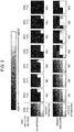
- FIG. 3 is a diagram illustrating difference in accuracy for positional deviation between distance information calculated by a conventional technique and distance information calculated by a technique of the present disclosure.
- the first image in which a subject having different distances in 16 tones is captured and the second image in which the subject is deviated vertically (Y in FIG. 3 ) and horizontally (X in FIG. 3 ) (an amount of deviation is shown by a numeral in FIG. 3 . the unit is a number of pixels) are used, and distance information calculated with the conventional technique and distance information calculated with the technique of the present disclosure are visually illustrated in FIG. 3 .
- the distance information does not represent the distance to the subject when the image is deviated by only one pixel; however, in the technique of the present disclosure, the distance information accurately represents the distance to the subject even when the pixel is deviated by one pixel vertically and horizontally.
- the distance information to the subject cannot be accurately calculated.
- the technique of the present disclosure even when the subject is moved by about one pixel during a period from acquisition of the first image to acquisition of the second image, the distance information to the subject can be accurately calculated without position correction.
- the present disclosure can be applied.
- FIG. 4 is a block diagram illustrating a functional configuration of an image processing device in the second exemplary embodiment.
- the same reference numerals are used for the same configurations as those in the first exemplary embodiment, and descriptions of the configurations are omitted.
- positional deviation between different images is corrected and then distance information is calculated.
- Image processing device 100 in the present exemplary embodiment further includes area divider 140 and area searcher 150.
- Area divider 140 is a processor for dividing a first image into a plurality of first small areas. A size of each of the first small areas divided is not particularly limited, and for example, the first area may be divided into the first small areas of four pixels ⁇ four pixels.
- Area searcher 150 is a processor that searches for a corresponding second small area for each of the plurality of first small areas divided, for another image other than the first image. That is, area searcher 150 corrects the positional deviation between images by searching for an image of the corresponding second small area in the second image for each of images of the first small areas of the first image and performing alignment.
- an image corresponding to each of the first small areas of the first image divided by area divider 140 is used, and the second image is searched for a corresponding image, and an area of a similar image is set to a second small area.
- a search algorithm although it is not particularly limited, in the present exemplary embodiment, block matching is used as the search algorithm.
- the search algorithm when it is possible to search for a corresponding area between images, another method may be used.
- the block matching searches for the corresponding second small area in the second image, for each of the first small areas of the first image.
- a difference is calculated between each of the first small areas of the first image and each of the areas of the second image, and an area in which the difference is the smallest is set to the second small area.
- the difference is calculated based on a sum of brightness differences for the area, for example.
- Frequency converter 110 in the present exemplary embodiment converts the image of each of the first small areas and the image of the corresponding second small area into frequency.
- Amplitude extractor 120 extracts an amplitude component for each of small areas that are each of the first small areas, and the corresponding second small area. That is, amplitude extractor 120 extracts the amplitude component for each of the first small areas and for each corresponding second small area.
- Distance information calculator 130 calculates distance information to a subject for each of the small areas. That is, distance information calculator 130 calculates the distance information to the subject for each of the first small areas each aligned with the corresponding second small area.
- the first image of a plurality of images is divided into the first small areas, and alignment with another image is performed for each of the first small areas, whereby the positional deviation between the images can be finely corrected. For that reason, the distance information to the subject can be calculated more accurately.
- the distance information can be accurately calculated even when some positional deviation occurs between the plurality of images, alignment between the images can be performed roughly.
- the distance information can be accurately calculated only when alignment is performed up to a unit of 0.1 pixels for an area with a weak edge.
- the distance information can be accurately calculated even in alignment of about a unit of one pixel.
- FIG. 5 is a block diagram illustrating a functional configuration of a distance information calculator in the present exemplary embodiment.
- distance information calculator 130 includes representative cost calculator 133 instead of cost calculator 131, and includes representative distance determiner 134 instead of distance determiner 132.
- Representative cost calculator 133 uses an amplitude component of each of first small areas of a first image, an amplitude component of a second small area of a second image, and input lens blur data to calculate a representative cost of a distance assumed, for each of the small areas. That is, representative cost calculator 133 calculates the representative cost of the distance assumed, for each of the first small areas each aligned with the corresponding second small area.
- one representative cost of the distance is calculated for one small area.
- Representative distance determiner 134 uses the representative cost of the distance calculated by representative cost calculator 133 to determine representative distance information for each of the small areas. Specifically, representative cost calculator 133 adds up frequency coefficient values, and representative distance determiner 134 calculates one piece of representative distance information for one small area as a representative value.
- the representative distance information is calculated for each of the small areas, not for each pixel, whereby a calculation cost and memory used can be significantly reduced. For that reason, fast processing can be achieved, and a device cost can be reduced.
- the distance information to the subject can be accurately calculated even when alignment between the images is not performed or alignment is roughly performed.
- the technique in the present disclosure is not limited to these exemplary embodiments, and can also be applied to an exemplary embodiment to which modification, replacement, addition, omission, and the like are performed.
- the distance information in only the part of the pixels may be calculated. Specifically, for example, it is not necessary to perform searching to all first small areas, and may perform searching to each of the first small areas of interest to calculate the distance information.
- first small areas divided do not have to be completely independent of each other, and may partially lie on top of one another (overlap each other).
- each of the first small areas is not limited to a square, and any shape can be selected.
- the OTF is used as an input; however, in general, the PSF is converted to the OTF by Fourier transform, so that the PSF may be used as the input, and Fourier transform may be performed internally to convert the PSF to the OTF.
- a program for causing a computer to execute image processing methods included in image processing device 100 and a recording medium in which the program is recorded are also within the scope of the present disclosure.
- the present disclosure can be applied to an image processing device and an image processing method that use a plurality of images respectively having focusing positions different from each other to calculate distance information to a subject.
- the present disclosure can be applied to a digital still camera, a digital movie camera, a mobile phone with a camera function, a smart phone, and the like.
Landscapes
- Engineering & Computer Science (AREA)
- Physics & Mathematics (AREA)
- General Physics & Mathematics (AREA)
- Computer Vision & Pattern Recognition (AREA)
- Multimedia (AREA)
- Signal Processing (AREA)
- Optics & Photonics (AREA)
- Electromagnetism (AREA)
- Radar, Positioning & Navigation (AREA)
- Remote Sensing (AREA)
- Theoretical Computer Science (AREA)
- Computing Systems (AREA)
- Image Processing (AREA)
- Length Measuring Devices By Optical Means (AREA)
- Measurement Of Optical Distance (AREA)
- Image Analysis (AREA)
- Studio Devices (AREA)
Applications Claiming Priority (2)
| Application Number | Priority Date | Filing Date | Title |
|---|---|---|---|
| JP2016038438 | 2016-02-29 | ||
| PCT/JP2016/002973 WO2017149565A1 (fr) | 2016-02-29 | 2016-06-21 | Dispositif de traitement d'image et procédé de traitement d'image |
Publications (2)
| Publication Number | Publication Date |
|---|---|
| EP3425331A1 true EP3425331A1 (fr) | 2019-01-09 |
| EP3425331A4 EP3425331A4 (fr) | 2019-02-27 |
Family
ID=59743529
Family Applications (1)
| Application Number | Title | Priority Date | Filing Date |
|---|---|---|---|
| EP16880193.4A Withdrawn EP3425331A4 (fr) | 2016-02-29 | 2016-06-21 | Dispositif de traitement d'image et procédé de traitement d'image |
Country Status (5)
| Country | Link |
|---|---|
| US (1) | US10455139B2 (fr) |
| EP (1) | EP3425331A4 (fr) |
| JP (1) | JP6354907B2 (fr) |
| CN (1) | CN107407560B (fr) |
| WO (1) | WO2017149565A1 (fr) |
Family Cites Families (13)
| Publication number | Priority date | Publication date | Assignee | Title |
|---|---|---|---|---|
| JP2963990B1 (ja) | 1998-05-25 | 1999-10-18 | 京都大学長 | 距離計測装置及び方法並びに画像復元装置及び方法 |
| JP5459768B2 (ja) * | 2009-10-28 | 2014-04-02 | 京セラ株式会社 | 被写体距離推定装置 |
| JP2011149931A (ja) * | 2009-12-21 | 2011-08-04 | Ricoh Co Ltd | 距離画像取得装置 |
| KR101675112B1 (ko) * | 2010-01-21 | 2016-11-22 | 삼성전자주식회사 | 거리 정보 추출 방법 및 상기 방법을 채용한 광학 장치 |
| US8330852B2 (en) * | 2010-04-30 | 2012-12-11 | Eastman Kodak Company | Range measurement using symmetric coded apertures |
| WO2011158508A1 (fr) * | 2010-06-17 | 2011-12-22 | パナソニック株式会社 | Dispositif de traitement d'image et procédé de traitement d'image |
| CN102812715B (zh) * | 2011-01-27 | 2015-08-19 | 松下电器产业株式会社 | 三维图像摄影装置以及三维图像拍摄方法 |
| US9047681B2 (en) * | 2011-07-07 | 2015-06-02 | Samsung Electronics Co., Ltd. | Depth image conversion apparatus and method |
| JP5830295B2 (ja) * | 2011-07-29 | 2015-12-09 | オリンパス株式会社 | 画像処理装置、画像処理装置の作動方法、及び画像処理プログラム |
| US8983221B2 (en) * | 2011-08-29 | 2015-03-17 | Panasonic Intellectual Property Management Co., Ltd. | Image processing apparatus, imaging apparatus, and image processing method |
| AU2011224051B2 (en) * | 2011-09-14 | 2014-05-01 | Canon Kabushiki Kaisha | Determining a depth map from images of a scene |
| DE102013110615B3 (de) * | 2013-09-26 | 2014-11-27 | Sick Ag | 3D-Kamera nach dem Stereoskopieprinzip und Verfahren zum Erfassen von Tiefenkarten |
| JP6272112B2 (ja) * | 2014-03-31 | 2018-01-31 | キヤノン株式会社 | 距離検出装置、撮像装置、距離検出方法及び視差量検出装置 |
-
2016
- 2016-06-21 EP EP16880193.4A patent/EP3425331A4/fr not_active Withdrawn
- 2016-06-21 WO PCT/JP2016/002973 patent/WO2017149565A1/fr not_active Ceased
- 2016-06-21 CN CN201680010718.6A patent/CN107407560B/zh active Active
- 2016-06-21 JP JP2017536901A patent/JP6354907B2/ja active Active
-
2017
- 2017-08-02 US US15/667,513 patent/US10455139B2/en active Active
Also Published As
| Publication number | Publication date |
|---|---|
| CN107407560A (zh) | 2017-11-28 |
| WO2017149565A1 (fr) | 2017-09-08 |
| JPWO2017149565A1 (ja) | 2018-03-08 |
| CN107407560B (zh) | 2019-09-24 |
| EP3425331A4 (fr) | 2019-02-27 |
| US10455139B2 (en) | 2019-10-22 |
| US20170332007A1 (en) | 2017-11-16 |
| JP6354907B2 (ja) | 2018-07-11 |
Similar Documents
| Publication | Publication Date | Title |
|---|---|---|
| US7711201B2 (en) | Method of and apparatus for generating a depth map utilized in autofocusing | |
| US20070189750A1 (en) | Method of and apparatus for simultaneously capturing and generating multiple blurred images | |
| US11348271B2 (en) | Image processing device and three-dimensional measuring system | |
| US10657672B2 (en) | Image processing device, image processing method and storage medium | |
| US20250379962A1 (en) | Motion correction for time-of-flight depth imaging | |
| Bailey et al. | Fast depth from defocus from focal stacks | |
| JPH05137047A (ja) | 焦点検出方法及び焦点検出装置 | |
| US11941835B2 (en) | Eye information estimate apparatus, eye information estimate method, and program | |
| Alam et al. | Metrics for evaluating the performance of joint-transform-correlation-based target recognition and tracking algorithms | |
| KR20100051359A (ko) | 영상 데이터 생성 방법 및 장치 | |
| TWI528783B (zh) | 產生深度影像之方法及其系統及電腦程式產品 | |
| JP6395429B2 (ja) | 画像処理装置、その制御方法及び記憶媒体 | |
| Leonard et al. | Adaptive nonlinear fringe-adjusted joint transform correlator | |
| US8260058B2 (en) | Template matching device, camera with template matching device, and program for allowing computer to carry out template matching | |
| JP2009223504A (ja) | 車両検出装置および方法、並びに、プログラム | |
| US10455139B2 (en) | Image processing device and image processing method for calculating distance information to a subject | |
| US20140152862A1 (en) | Image processing apparatus, image pickup apparatus, image pickup system, image processing method, and non-transitory computer-readable storage medium | |
| JP5170005B2 (ja) | 画像処理装置、画像処理方法、およびプログラム | |
| US11475233B2 (en) | Image processing device and image processing method | |
| Alpatov et al. | A composite algorithm for variable size object tracking for high performance FPGA-based on-board vision systems | |
| US9014464B2 (en) | Measurement device, measurement method, and computer program product | |
| KR101919879B1 (ko) | 사용자 인터랙션 정보 기반 깊이 정보 영상 보정 장치 및 방법 | |
| JP6350205B2 (ja) | 処理装置、処理方法および処理プログラム | |
| US8804251B2 (en) | Accurate auto-focus method | |
| WO2021114061A1 (fr) | Dispositif électrique, et procédé de commande d'un dispositif électrique |
Legal Events
| Date | Code | Title | Description |
|---|---|---|---|
| STAA | Information on the status of an ep patent application or granted ep patent |
Free format text: STATUS: UNKNOWN |
|
| STAA | Information on the status of an ep patent application or granted ep patent |
Free format text: STATUS: THE INTERNATIONAL PUBLICATION HAS BEEN MADE |
|
| PUAI | Public reference made under article 153(3) epc to a published international application that has entered the european phase |
Free format text: ORIGINAL CODE: 0009012 |
|
| STAA | Information on the status of an ep patent application or granted ep patent |
Free format text: STATUS: REQUEST FOR EXAMINATION WAS MADE |
|
| 17P | Request for examination filed |
Effective date: 20170707 |
|
| AK | Designated contracting states |
Kind code of ref document: A1 Designated state(s): AL AT BE BG CH CY CZ DE DK EE ES FI FR GB GR HR HU IE IS IT LI LT LU LV MC MK MT NL NO PL PT RO RS SE SI SK SM TR |
|
| AX | Request for extension of the european patent |
Extension state: BA ME |
|
| A4 | Supplementary search report drawn up and despatched |
Effective date: 20190125 |
|
| RIC1 | Information provided on ipc code assigned before grant |
Ipc: G01C 3/06 20060101ALI20190121BHEP Ipc: H04N 1/32 20060101ALI20190121BHEP Ipc: H04N 5/232 20060101ALI20190121BHEP Ipc: G01C 3/32 20060101ALI20190121BHEP Ipc: G01C 3/08 20060101ALI20190121BHEP Ipc: H04N 19/62 20140101ALI20190121BHEP Ipc: G02B 7/28 20060101ALI20190121BHEP Ipc: G06T 7/571 20170101AFI20190121BHEP Ipc: G02B 7/36 20060101ALI20190121BHEP Ipc: G02B 7/38 20060101ALI20190121BHEP Ipc: G06T 1/00 20060101ALI20190121BHEP |
|
| DAV | Request for validation of the european patent (deleted) | ||
| DAX | Request for extension of the european patent (deleted) | ||
| GRAP | Despatch of communication of intention to grant a patent |
Free format text: ORIGINAL CODE: EPIDOSNIGR1 |
|
| STAA | Information on the status of an ep patent application or granted ep patent |
Free format text: STATUS: GRANT OF PATENT IS INTENDED |
|
| RIC1 | Information provided on ipc code assigned before grant |
Ipc: G01C 3/06 20060101ALI20190614BHEP Ipc: H04N 1/32 20060101ALI20190614BHEP Ipc: G01C 3/08 20060101ALI20190614BHEP Ipc: G06T 7/571 20170101AFI20190614BHEP Ipc: G02B 7/28 20060101ALI20190614BHEP Ipc: H04N 19/62 20140101ALI20190614BHEP Ipc: G02B 7/38 20060101ALI20190614BHEP Ipc: G01C 3/32 20060101ALI20190614BHEP Ipc: G06T 1/00 20060101ALI20190614BHEP Ipc: H04N 5/232 20060101ALI20190614BHEP Ipc: G02B 7/36 20060101ALI20190614BHEP |
|
| INTG | Intention to grant announced |
Effective date: 20190704 |
|
| STAA | Information on the status of an ep patent application or granted ep patent |
Free format text: STATUS: THE APPLICATION IS DEEMED TO BE WITHDRAWN |
|
| 18D | Application deemed to be withdrawn |
Effective date: 20191115 |