EP3425337A1 - Positionnement d'un ensemble de véhicules - Google Patents
Positionnement d'un ensemble de véhicules Download PDFInfo
- Publication number
- EP3425337A1 EP3425337A1 EP17275099.4A EP17275099A EP3425337A1 EP 3425337 A1 EP3425337 A1 EP 3425337A1 EP 17275099 A EP17275099 A EP 17275099A EP 3425337 A1 EP3425337 A1 EP 3425337A1
- Authority
- EP
- European Patent Office
- Prior art keywords
- positions
- vehicles
- targets
- vehicle
- isovist
- Prior art date
- Legal status (The legal status is an assumption and is not a legal conclusion. Google has not performed a legal analysis and makes no representation as to the accuracy of the status listed.)
- Ceased
Links
Images


Classifications
-
- G—PHYSICS
- G01—MEASURING; TESTING
- G01C—MEASURING DISTANCES, LEVELS OR BEARINGS; SURVEYING; NAVIGATION; GYROSCOPIC INSTRUMENTS; PHOTOGRAMMETRY OR VIDEOGRAMMETRY
- G01C21/00—Navigation; Navigational instruments not provided for in groups G01C1/00 - G01C19/00
- G01C21/20—Instruments for performing navigational calculations
- G01C21/203—Instruments for performing navigational calculations specially adapted for water-borne vessels
-
- G—PHYSICS
- G01—MEASURING; TESTING
- G01S—RADIO DIRECTION-FINDING; RADIO NAVIGATION; DETERMINING DISTANCE OR VELOCITY BY USE OF RADIO WAVES; LOCATING OR PRESENCE-DETECTING BY USE OF THE REFLECTION OR RERADIATION OF RADIO WAVES; ANALOGOUS ARRANGEMENTS USING OTHER WAVES
- G01S13/00—Systems using the reflection or reradiation of radio waves, e.g. radar systems; Analogous systems using reflection or reradiation of waves whose nature or wavelength is irrelevant or unspecified
- G01S13/86—Combinations of radar systems with non-radar systems, e.g. sonar, direction finder
- G01S13/867—Combination of radar systems with cameras
-
- G—PHYSICS
- G01—MEASURING; TESTING
- G01S—RADIO DIRECTION-FINDING; RADIO NAVIGATION; DETERMINING DISTANCE OR VELOCITY BY USE OF RADIO WAVES; LOCATING OR PRESENCE-DETECTING BY USE OF THE REFLECTION OR RERADIATION OF RADIO WAVES; ANALOGOUS ARRANGEMENTS USING OTHER WAVES
- G01S13/00—Systems using the reflection or reradiation of radio waves, e.g. radar systems; Analogous systems using reflection or reradiation of waves whose nature or wavelength is irrelevant or unspecified
- G01S13/88—Radar or analogous systems specially adapted for specific applications
- G01S13/93—Radar or analogous systems specially adapted for specific applications for anti-collision purposes
- G01S13/937—Radar or analogous systems specially adapted for specific applications for anti-collision purposes of marine craft
-
- G—PHYSICS
- G01—MEASURING; TESTING
- G01S—RADIO DIRECTION-FINDING; RADIO NAVIGATION; DETERMINING DISTANCE OR VELOCITY BY USE OF RADIO WAVES; LOCATING OR PRESENCE-DETECTING BY USE OF THE REFLECTION OR RERADIATION OF RADIO WAVES; ANALOGOUS ARRANGEMENTS USING OTHER WAVES
- G01S13/00—Systems using the reflection or reradiation of radio waves, e.g. radar systems; Analogous systems using reflection or reradiation of waves whose nature or wavelength is irrelevant or unspecified
- G01S13/66—Radar-tracking systems; Analogous systems
- G01S13/72—Radar-tracking systems; Analogous systems for two-dimensional [2D] tracking, e.g. combination of angle and range tracking, track-while-scan radar
- G01S13/723—Radar-tracking systems; Analogous systems for two-dimensional [2D] tracking, e.g. combination of angle and range tracking, track-while-scan radar by using numerical data
-
- G—PHYSICS
- G01—MEASURING; TESTING
- G01S—RADIO DIRECTION-FINDING; RADIO NAVIGATION; DETERMINING DISTANCE OR VELOCITY BY USE OF RADIO WAVES; LOCATING OR PRESENCE-DETECTING BY USE OF THE REFLECTION OR RERADIATION OF RADIO WAVES; ANALOGOUS ARRANGEMENTS USING OTHER WAVES
- G01S13/00—Systems using the reflection or reradiation of radio waves, e.g. radar systems; Analogous systems using reflection or reradiation of waves whose nature or wavelength is irrelevant or unspecified
- G01S13/02—Systems using reflection of radio waves, e.g. primary radar systems; Analogous systems
- G01S2013/0236—Special technical features
- G01S2013/0272—Multifunction radar
-
- G—PHYSICS
- G01—MEASURING; TESTING
- G01S—RADIO DIRECTION-FINDING; RADIO NAVIGATION; DETERMINING DISTANCE OR VELOCITY BY USE OF RADIO WAVES; LOCATING OR PRESENCE-DETECTING BY USE OF THE REFLECTION OR RERADIATION OF RADIO WAVES; ANALOGOUS ARRANGEMENTS USING OTHER WAVES
- G01S13/00—Systems using the reflection or reradiation of radio waves, e.g. radar systems; Analogous systems using reflection or reradiation of waves whose nature or wavelength is irrelevant or unspecified
- G01S13/88—Radar or analogous systems specially adapted for specific applications
- G01S13/93—Radar or analogous systems specially adapted for specific applications for anti-collision purposes
- G01S13/931—Radar or analogous systems specially adapted for specific applications for anti-collision purposes of land vehicles
- G01S2013/9325—Radar or analogous systems specially adapted for specific applications for anti-collision purposes of land vehicles for inter-vehicle distance regulation, e.g. navigating in platoons
Definitions
- the present invention relates to positioning a set of vehicles.
- an aim may be to determine the positions of one or more escort vehicle around a convoy in a manner that will best protect it from hostile entities, such as pirate boats who want to capture ships from the convoy.
- hostile entities such as pirate boats who want to capture ships from the convoy.
- the visibility of the convoy and the escort vehicle(s) may be limited by obstacles in the environment, such as shore lines, islands and third party vessels. The pirates can be crafty and use such obstacles as cover in order to get close to the convoy without being detected before starting their final run, thus reducing the reaction time available to the escort vehicles.
- Embodiments of the present invention are intended to address at least some of the above technical problems.
- Embodiments can automatically compute positions for one or more vehicles, such as vehicles escorting a protected object, so that the probability of the escort vehicle(s) intercepting one or more pirate vehicles aiming for the protected object is substantially maximised.
- a (computer-implemented) method of positioning a set of vehicles with respect to an object and a set of targets comprising:
- the set of vehicles may comprise escort vehicles.
- the object may comprise at least one vehicle to be protected/screened by the escort vehicles.
- the set of targets may comprise a set of hostile vehicles aiming to attack the at least one vehicle protected/screened by the set of escort vehicles.
- the predetermined proximity may represent a distance at which one of the escort vehicles can intercept at least one of the hostile vehicles.
- the step of computing the estimated positions of the targets may comprise positioning a number of the targets at positions where detectability by the at least one sensor device is limited.
- the number may comprise a proportion (e.g. at least 10%) of the set of targets.
- the step of computing estimated positions of the targets may comprise:
- the number of the targets may be positioned at a said outer edge of the isovist that is nearest to the object.
- the step of computing estimated positions of the targets may comprise:
- the step of computing the plurality of positions of the vehicles in the environment based on the computed position of the targets may comprise:
- the Region of Approach may be computed using any suitable approach, including the method described in the "Search and Screening" paper by Koopman referenced below.
- the step of computing the plurality of positions of the vehicles may comprise determining a plurality of starting positions for the vehicle, each starting position being within a notional circle having a radius calculated based on a velocity of the target, a velocity of the vehicle and a period of time until potential interception of the target by the vehicle.
- the step of selecting a subset of the positions may comprise:
- the step of selecting a subset of the positions may comprise:
- the step of selecting a subset of the positions may comprise:
- the step of selecting the subset of the positions may comprise applying an optimisation technique to the computed ratios.
- the optimisation technique may comprise a heuristic, annealing or particle swarm optimisation technique.
- a computer program product comprising instructions which, when the program is executed by a computer, cause the computer to carry out a method substantially as described herein.
- a system adapted to position a set of vehicles with respect to an object and a set of targets, the system comprising at least one processor configured to:
- the system may comprise a management system configured to output signals representing the selected positions.
- aspects of the invention may provide a vehicle, or vehicle control system, configured to receive and execute signals representing positions output by a method/system substantially as described herein.
- a vehicle e.g. an at least partly autonomous vehicle, or a manned vehicle
- a component such as a computing device or control system, configured to execute a method substantially as described herein.
- FIG. 1 schematically illustrates a set of vehicles 102A, 102B, 102C.
- these vehicles comprise escort vehicles in the form of Unmanned Surface Vehicles (USVs), although it should be understood that the number (one or more) and type of vehicles can vary.
- Each of the escort vehicles 102 may be at least partly autonomous. That is, the positioning of the vehicle may be directly automatically controlled by computer-generated signals, rather than by a human operator.
- the extent of the autonomous control can vary. For example, the direction and/or speed of the vehicle may be controlled by computer-generated signals, whilst other features or sub-systems of the vehicle may be under (local or remote) human control. Also, it may be possible to switch the vehicle between fully-autonomous, partly-autonomous and/or manual control methods.
- Figure 1 also illustrates an object 104 that is to be screened/protected by the escort vehicles 102.
- the object comprises a convoy that includes a set of ships, which may be of different types, although it should be understood that this is exemplary only.
- the convoy may be travelling at a relatively slow speed compared to the other vehicles/objects, or it may be static at times.
- Figure 1 further illustrates a set of moving targets 106A, 106B, 106C that are being controlled to move generally towards the convoy 104 in order take some action in relation to it, e.g. an attack.
- the targets 106 will be referred to below as "pirate vehicles" and are to be targeted by the escort vehicles in order to prevent, or at least limit, an attack on the convoy.
- the pirate vehicles may be under (local or remote) human control, and/or may be at least partly autonomous.
- the pirate vehicles may be of different types to each other and, again, it should be understood that the number (one or more) and type of targets are merely exemplary.
- the vehicles 102, 104, 106 comprise waterborne vehicles, such as USVs, ships, boats or submarines.
- waterborne vehicles such as USVs, ships, boats or submarines.
- the types of the vehicles may vary, and they may include various kinds of land-based (e.g. all-terrain vehicles, etc) and/or airborne vehicles (e.g. airplanes, helicopters, drones, etc).
- some of the pirate vehicles 106A, 106B are located behind a land mass 107 and so are not in the line of sight of a sensor device 108 located on the convoy 104.
- the sensor device has a range denoted by circle 110 and one of the pirate vehicles 106C is also located outside of the range.
- the pirate vehicles may not be detectable until they are relatively close to the convoy, thereby giving the escort vehicles less time to try to intercept them and increasing the risk of a damaging attack.
- Embodiments can therefore be intended to compute positions for the escort vehicles in the environment surrounding the convoy where they are most likely to be able to intercept pirate vehicles in time should they appear, e.g. from behind a landmass or other obstacle. Embodiments can implement this by estimating positions of "virtual" pirates at locations where there is most risk of a real pirate vehicle lurking undetected. The escort vehicles can then be positioned so that they are ready to intercept these virtual pirates. Therefore, if a real pirate vehicle does appear at/near the position of a virtual pirate then it can be quickly intercepted by at least one of the escort vehicles.
- FIG. 2 is a block diagram of a computing device 200.
- This type of computing device may be installed on board at least one of the escort vehicles 102 and/or at least one of the convoy vehicles 104.
- the computing device may be located remotely (e.g. at a land base) and can be in communication with one or more devices on board one or more of the vehicles 102, 104.
- the computing device 200 may be at a location remote from the vehicles and communicate with a device on board one of the convoy vehicles 104. That device may then send control signals to devices/systems on board the escort vehicles 102 in order to autonomously position them.
- the computing device 200 may be part of a combat management system that can command and control unmanned off-board systems.
- the system may be in communication with a mission planning tool that formulates mission plans for off-board systems by decomposing the mission objectives, as stated by an operator, into tasks that are assigned to the available assets and the execution times of which are scheduled.
- the decomposition step can encode tactics and standing orders and is thus well placed to compute optimal escort positons for a given convoying mission objective.
- the computing device 200 typically includes a processor 202 and a memory 204.
- the computing device can further include at least one communications interface 206 that allows it to transfer data to/from other devices, such as other computing devices installed on broad one or more of the (other) escort vehicles 102 and/or on one or more of the (other) convoy vehicles 104.
- the communications interface will typically provide wireless communication over a communications network and may transfer data in an encrypted manner.
- the computing device may comprise further conventional components, such as a display, user interface, external storage, etc, that need not be described here in detail. In some cases the components and/or functions of the computing device may be distributed.
- the computing device 200 may further include (or be in communication with) a vehicle controller 207.
- vehicle controller can comprise circuitry or the like that can directly control one or more positioning components/sub-system of the escort vehicle, including ones that can control the direction and speed of the vehicle, thereby allowing it to function as an at least partly autonomous vehicle.
- the computing device 200 may include at least one sensor device 208.
- the computing device may be in direct or indirect communication with at least one sensor device (e.g. over a communications network or wired/wireless connection).
- the at least one sensor device can be associated with the convoy 104.
- the sensor device(s) may be installed on one of the convoy vehicles.
- the sensor device(s) may be located on another moveable object/vehicle (e.g. an autonomous vehicle, such as one of the escort vehicles 102) that maintains close proximity to the convoy, e.g. by following it.
- the sensor device(s) may be controllable, e.g.
- the sensor device(s) may comprise an electro-optical sensor, a radar-based sensor and/or any other suitable device.
- the device may comprise a still/video camera, an infra-red imaging device, an ultra-violet imaging device, etc.
- Figure 3 is a flowchart illustrating steps that can be performed by an example embodiment, e.g. by code executing on the computing device 200. It will be appreciated that the illustrated steps are exemplary only and in alternative embodiments some of them may be omitted, re-ordered and/or performed concurrently rather than sequentially. Further, additional steps (not illustrated) may be performed. The skilled person will understand that the steps can be implemented by hardware and/or software, using any suitable programming languages/techniques and data structures, where appropriate. The method may be started and/or terminated by a user, or automatically when certain conditions are met, e.g. based on external control signals being received.
- an isovist that describes the visible space around the convoy 104.
- An isovist comprises a volume of space visible from a certain point and time, with respect to its environment.
- the embodiment may generate the isovist from a computation of the line of sight using data obtained from the at least one sensor device 208 that is associated with the convoy 104.
- the isovist may be generated using any suitable technique, e.g. raytracing or visibility computations, based on data provided by an electro-optical sensor.
- an angle variable can initially be set to zero, with the method finding the closest intersection in the line of maximum sensor range from the origin in the direction of this angle. The angle is incremented until a circle is complete to generate the isovist.
- the isovist can include an area in which an object is detectable when illuminated with one or more radar-based sensor device 208 from a given point.
- the isovist does not have a clear crisp edge, but is described by a probability field where the probability of detection diminished towards the edges.
- Figure 4 illustrates an example of an isovist 400 generated based on data provided by an electro-optical sensor.
- the example isovist is approximated using a union of triangles as an internal representation, but it should be understood that this is exemplary only. In some places the line of sight of the sensor did not extend to the outer edge of the isovist. Items 402, 404 and 406 in the Figure represent generalised obstacles that block the line of sight.
- Figure 5 illustrates an example of an isovist 500 generated based on data provided by a radar.
- positions in the isovist are colour/shaded based on the probability of detectability by the radar, with lighter colours/shades representing a higher probability and darker (non-black) representing lower probability.
- the isovist is a function of the sensor device(s) 208 being used, the disposition of the convoy 104 associated with the sensor device(s), all/some of the escort vehicles 102 and/or the pirate vehicles 106 and any landmass or other obstacles.
- Embodiments can therefore process additional information in order to generate the isovist at the step 302.
- embodiments may receive data relating to positions/routes of the vehicles 102, 104 and/or 106.
- embodiments can determine/predict the positions of the convoy, the escort vehicles and other traffic. This predicted position data, together with geographical data (terrain elevation, etc), form the data that is input to the isovist computation.
- Embodiments may also receive and process data relating to the at least one sensor device 208, e.g. information regarding sensor type, position, etc.
- Embodiments can compute an estimated position of each of the pirate vehicles 106 in the generated isovist.
- Embodiments may generate (or receive input representing) an initial number (e.g. 1000) of virtual pirates.
- Embodiments may position at least some (and typically, for example, between 100 and 1000, i.e. at least 10%) of the pirate vehicles 106 where detectability from the sensor device(s) 208 associated with the convoy 104 is limited.
- the pirate vehicles 106 could attack the convoy 104 from the edge of its visibility, especially where that edge is very close to the convoy (e.g. 1 to 2 nautical miles, where the pirate has a speed of 30 knots, which would leave the escort vehicle just 4 minutes to react) such that the pirates could be concealed by other vessels and/or obstacles, such as a landmass.
- a fixed number e.g. 100 to 1000, i.e. at least 10%
- the virtual pirates 106 may be placed in a 2D or 3D representation of the environment surrounding the convoy 104 that is generated using the isovist.
- a coordinate system can be used for this representation of the environment, with the origin of the coordinate system being located at the centre of the convoy (e.g. where a sensor is positioned) and moving with the convoy.
- the coordinate system can be oriented such that its y-axis is oriented to be parallel with the track of the convoy, i.e. course over a surface.
- the isovist can be expressed (e.g.
- the positions of the virtual pirates 106 in the environment may be generated by randomly sampling an edge of the isovist. During this sampling process, the likelihood that a virtual pirate is placed in location 'x' is a function of the inverse distance to the convoy 104, i.e. a large number of virtual pirates is placed on those isovist edges that are close to the convoy.
- the generated isovist is not black and white, but, rather, a field of detection probability values.
- different sampling strategies can be used for electro-magnetic and radar-based sensor devices.
- a fixed number e.g. 100 to 1000, i.e. at least 10%
- the virtual pirates may be placed in the representation of the environment surrounding the convoy 104 by randomly sampling the entire area of the isovist.
- the likelihood that a virtual pirate is placed in location 'x' is a function of the inverse of the probability of detection by the radar sensor device(s), i.e. more virtual pirates are placed in locations of low detectability compared with regions of high detectability.
- embodiments can compute positions of the escort vehicles 102 in the representation of the environment surrounding the convoy 104 based on the estimated positions of the pirate vehicles 106. Multiple sets of possible positions for all/some of the escort vehicles can be computed. Embodiments can use these with the aim of positioning the escort vehicles in the environment such that the likelihood of them coming into predetermined proximity with at least one real/actual pirate vehicle 106 (that has not already been detected) is increased/maximized, e.g. in order to successfully intercept an attack against the convoy 104 by a real pirate. Thus, an aim can be to place the escort vehicles such that the largest possible number of pirate vehicles is interceptable.
- Embodiments will normally assume that the escort vehicles must be able to intercept the fast boats of the pirates.
- the predetermined proximity may be a fixed value (e.g. expressed as a straight-line distance or radius from the position of a pirate vehicle), or it may be updatable by an operator and/or automatically (e.g. depending on real-time factors, such as velocity of an escort and/or pirate vehicle; proximity of pirate vehicle to other vehicles/objects; type of action (such as collide, fire weapon from a distance, jam communications from a distance, etc) to be taken, and so on).
- the "Region of Approach" concept as described, for example, in Bernhard Osgood Koopman, "Search and Screening", Volume 56 of United States Office of Naval Operations. Operations Evaluation Group: OEG-report, Operations Evaluation Group, 1946, can be used to determine the area from which each pirate vehicle 106 can be intercepted by a given escort vehicle 102 placed at a given location.
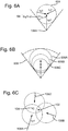
- a summary of this Region of Approach computation is schematically illustrated in Figures 6A - 6C .
- a family of circles is obtained, e.g. three circles 606A - 606C for three different values of t.
- Two cases can be distinguished: a) v E ⁇ v P , and b) v E ⁇ v p .
- the largest circle 606A i.e. of size v E t max encloses all relevant starting locations.
- all relevant starting locations are described by a family of circles 606A - 606C and the area of interest is bounded by a circular sector 608 with an arc of sin -1 (v E /v p ) degrees.
- FIG. 6C three virtual pirates 106A - 106C are shown by their track arrows, the convoy 104 located at c and an escort vehicle 102 located at x. As x is located within all three of the circles, the escort vehicle is able to intercept any one of the three pirates and will be in a good position should a real pirate appear from a similar location and direction.
- each of the computed positions can have an associated value representing a number (zero or more) of the pirate vehicles 106 that are within the predetermined proximity of the escort vehicle 102 that is at that computed position.
- the subset of escort vehicle 102 positions can be computed using an optimisation approach (e.g. a heuristic approach, such as Simulated Annealing or Particle Swarm Optimisation) to select the combination of positions having the best ratios P ; however, other approaches may be used.
- an optimisation approach e.g. a heuristic approach, such as Simulated Annealing or Particle Swarm Optimisation
- step 310 embodiments can use the subset of positions selected at the step 308 to position the escort vehicles 102 so that they generally correspond to the selected positions.
- This can involve sending signals to the vehicle controller 207 of one or more of the escort vehicles in order to directly control the positions of the vehicles. Additionally or alternatively, this can include displaying information to assist a (local or remote) operator with controlling the positions of one or more of the escort vehicles and/or for simulation purposes.
- Such operations may be done substantially in real-time as the method is executed, or position information may be stored for future use (e.g. to pre-emptively position at least some escort vehicles as soon as a warning regarding a possible attack is received).
- embodiments of the method may be performed in order to plan before a mission, e.g. repeat its calculations for future nominal time steps. In other cases, embodiments of the method may be performed initially in order to plan while the mission is being executed, then after a period of time/waiting its calculations are repeated so that the positions for the escort vehicles are recomputed based on up-to-date information obtained from the at least one sensor device.
- Embodiments can use time discretised into equally sized slots for repeating the analysis for each time slot (with control returning to the step 302 from the step 310). In order to save on computational effort, the solution of the previous time step may be used as an initial guess for the current time step.
- embodiments can compute optimum screening locations for escort vehicles such that visibility restrictions due to other vessels or land is taken into account.
- Embodiments can compute vehicle positions shortly before a mission is started or during an ongoing mission.
- embodiments may be provided for situations other than vehicles escorting a convoy to protect it from pirate vehicles, such as meeting vehicles carrying supplies to pick up the supplies and transfer them to another vehicle or location, etc.
Landscapes
- Engineering & Computer Science (AREA)
- Radar, Positioning & Navigation (AREA)
- Remote Sensing (AREA)
- Physics & Mathematics (AREA)
- General Physics & Mathematics (AREA)
- Computer Networks & Wireless Communication (AREA)
- Automation & Control Theory (AREA)
- Ocean & Marine Engineering (AREA)
- Electromagnetism (AREA)
- Traffic Control Systems (AREA)
Priority Applications (9)
| Application Number | Priority Date | Filing Date | Title |
|---|---|---|---|
| EP17275099.4A EP3425337A1 (fr) | 2017-07-07 | 2017-07-07 | Positionnement d'un ensemble de véhicules |
| EP18732865.3A EP3649433B1 (fr) | 2017-07-07 | 2018-06-26 | Positionnement d'un ensemble de véhicules |
| NZ760724A NZ760724B2 (en) | 2018-06-26 | Positioning a set of vehicles | |
| US16/629,161 US11380207B2 (en) | 2017-07-07 | 2018-06-26 | Positioning a set of vehicles |
| AU2018295438A AU2018295438B2 (en) | 2017-07-07 | 2018-06-26 | Positioning a set of vehicles |
| CA3069099A CA3069099A1 (fr) | 2017-07-07 | 2018-06-26 | Positionnement d'un ensemble de vehicules |
| ES18732865T ES2899311T3 (es) | 2017-07-07 | 2018-06-26 | Posicionamiento de un conjunto de vehículos |
| PCT/GB2018/051774 WO2019008326A1 (fr) | 2017-07-07 | 2018-06-26 | Positionnement d'un ensemble de véhicules |
| SA520410960A SA520410960B1 (ar) | 2017-07-07 | 2020-01-02 | تحديد موضع مجموعة من المركبات |
Applications Claiming Priority (1)
| Application Number | Priority Date | Filing Date | Title |
|---|---|---|---|
| EP17275099.4A EP3425337A1 (fr) | 2017-07-07 | 2017-07-07 | Positionnement d'un ensemble de véhicules |
Publications (1)
| Publication Number | Publication Date |
|---|---|
| EP3425337A1 true EP3425337A1 (fr) | 2019-01-09 |
Family
ID=59315526
Family Applications (1)
| Application Number | Title | Priority Date | Filing Date |
|---|---|---|---|
| EP17275099.4A Ceased EP3425337A1 (fr) | 2017-07-07 | 2017-07-07 | Positionnement d'un ensemble de véhicules |
Country Status (1)
| Country | Link |
|---|---|
| EP (1) | EP3425337A1 (fr) |
Cited By (1)
| Publication number | Priority date | Publication date | Assignee | Title |
|---|---|---|---|---|
| CN111132029A (zh) * | 2019-10-16 | 2020-05-08 | 张苏 | 基于地形约束的定位方法及装置 |
Citations (2)
| Publication number | Priority date | Publication date | Assignee | Title |
|---|---|---|---|---|
| EP2355451A1 (fr) * | 2010-02-01 | 2011-08-10 | Thales Nederland B.V. | Système distribué de surveillance maritime |
| US20160025850A1 (en) * | 2014-06-03 | 2016-01-28 | Watchstander, LLC | Autonomous Robotic Mobile Threat Security System |
-
2017
- 2017-07-07 EP EP17275099.4A patent/EP3425337A1/fr not_active Ceased
Patent Citations (2)
| Publication number | Priority date | Publication date | Assignee | Title |
|---|---|---|---|---|
| EP2355451A1 (fr) * | 2010-02-01 | 2011-08-10 | Thales Nederland B.V. | Système distribué de surveillance maritime |
| US20160025850A1 (en) * | 2014-06-03 | 2016-01-28 | Watchstander, LLC | Autonomous Robotic Mobile Threat Security System |
Non-Patent Citations (2)
| Title |
|---|
| BERNHARD OSGOOD KOOPMAN: "Search and Screening", vol. 56, 1946, OPERATIONS EVALUATION GROUP: OEG-REPORT, OPERATIONS EVALUATION GROUP |
| MYLANDER; SANDERS: "Naval Operations Analysis", 2002, NAVAL INSTITUTE PRESS |
Cited By (1)
| Publication number | Priority date | Publication date | Assignee | Title |
|---|---|---|---|---|
| CN111132029A (zh) * | 2019-10-16 | 2020-05-08 | 张苏 | 基于地形约束的定位方法及装置 |
Similar Documents
| Publication | Publication Date | Title |
|---|---|---|
| National Research Council et al. | Autonomous vehicles in support of naval operations | |
| US11380207B2 (en) | Positioning a set of vehicles | |
| US9240001B2 (en) | Systems and methods for vehicle survivability planning | |
| US9030347B2 (en) | Preemptive signature control for vehicle survivability planning | |
| EP1857768A2 (fr) | Programmateur de recherche de route | |
| US20170059333A1 (en) | Decision support and control systems including various graphical user interfaces configured for displaying multiple transit options for a platform with respect to hazard and objects and related methods | |
| WO2014021961A2 (fr) | Systèmes et procédés de planification de la capacité de survie d'un véhicule | |
| US20070269077A1 (en) | Sensor scan planner | |
| US8831793B2 (en) | Evaluation tool for vehicle survivability planning | |
| KR20200015311A (ko) | 위성항법 무인이동체 기만 장치 및 방법 | |
| sub Song et al. | Conceptual design of future undersea unmanned vehicle (UUV) system for mine disposal | |
| GB2564415A (en) | Positioning a set of vehicles | |
| EP3425337A1 (fr) | Positionnement d'un ensemble de véhicules | |
| AU2018357056B2 (en) | Positioning at least one vehicle in relation to a set of moving targets | |
| Alves | Economic tradeoff analysis of a product line architecture approach through model-based systems engineering: a case study of future mine countermeasures unmanned underwater vehicles | |
| Kragelund | Optimal sensor-based motion planning for autonomous vehicle teams | |
| Doyle | Mission Engineering Methodology for Realization of Unmanned Surface Vessel Operations | |
| Marcus | Sensor and Signature Modeling for Aircraft Conceptual Development | |
| Yordanova | Intelligent adaptive underwater sensor networks | |
| Goldfrank | Cyber Risks in Networked Autonomous Systems | |
| Rothal et al. | A sampling of NPS theses, reports and papers on UxS | |
| Ross | Automation of P-3 Simulations to Improve Operator Workload | |
| Marlatt | A sampling of NPS theses, reports and papers on UxS | |
| EP3476683A1 (fr) | Positionnement d'au moins un véhicule par rapport à un ensemble de cibles mobiles | |
| Stottler et al. | Intelligent surface threat identification system (ISTIS) |
Legal Events
| Date | Code | Title | Description |
|---|---|---|---|
| PUAI | Public reference made under article 153(3) epc to a published international application that has entered the european phase |
Free format text: ORIGINAL CODE: 0009012 |
|
| AK | Designated contracting states |
Kind code of ref document: A1 Designated state(s): AL AT BE BG CH CY CZ DE DK EE ES FI FR GB GR HR HU IE IS IT LI LT LU LV MC MK MT NL NO PL PT RO RS SE SI SK SM TR |
|
| AX | Request for extension of the european patent |
Extension state: BA ME |
|
| STAA | Information on the status of an ep patent application or granted ep patent |
Free format text: STATUS: THE APPLICATION HAS BEEN REFUSED |
|
| 18R | Application refused |
Effective date: 20190127 |