EP3425367A1 - Procédé de mesure et dispositif de mesure de perte dépendante du mode - Google Patents
Procédé de mesure et dispositif de mesure de perte dépendante du mode Download PDFInfo
- Publication number
- EP3425367A1 EP3425367A1 EP16892744.0A EP16892744A EP3425367A1 EP 3425367 A1 EP3425367 A1 EP 3425367A1 EP 16892744 A EP16892744 A EP 16892744A EP 3425367 A1 EP3425367 A1 EP 3425367A1
- Authority
- EP
- European Patent Office
- Prior art keywords
- mode
- light
- optical fiber
- spatial
- intensity
- Prior art date
- Legal status (The legal status is an assumption and is not a legal conclusion. Google has not performed a legal analysis and makes no representation as to the accuracy of the status listed.)
- Withdrawn
Links
Images


Classifications
-
- G—PHYSICS
- G01—MEASURING; TESTING
- G01M—TESTING STATIC OR DYNAMIC BALANCE OF MACHINES OR STRUCTURES; TESTING OF STRUCTURES OR APPARATUS, NOT OTHERWISE PROVIDED FOR
- G01M11/00—Testing of optical apparatus; Testing structures by optical methods not otherwise provided for
- G01M11/30—Testing of optical devices, constituted by fibre optics or optical waveguides
- G01M11/33—Testing of optical devices, constituted by fibre optics or optical waveguides with a light emitter being disposed at one fibre or waveguide end-face, and a light receiver at the other end-face
- G01M11/337—Testing of optical devices, constituted by fibre optics or optical waveguides with a light emitter being disposed at one fibre or waveguide end-face, and a light receiver at the other end-face by measuring polarization dependent loss [PDL]
-
- G—PHYSICS
- G02—OPTICS
- G02B—OPTICAL ELEMENTS, SYSTEMS OR APPARATUS
- G02B6/00—Light guides; Structural details of arrangements comprising light guides and other optical elements, e.g. couplings
- G02B6/02—Optical fibres with cladding with or without a coating
- G02B6/02004—Optical fibres with cladding with or without a coating characterised by the core effective area or mode field radius
- G02B6/02009—Large effective area or mode field radius, e.g. to reduce nonlinear effects in single mode fibres
- G02B6/02014—Effective area greater than 60 square microns in the C band, i.e. 1530-1565 nm
-
- G—PHYSICS
- G01—MEASURING; TESTING
- G01M—TESTING STATIC OR DYNAMIC BALANCE OF MACHINES OR STRUCTURES; TESTING OF STRUCTURES OR APPARATUS, NOT OTHERWISE PROVIDED FOR
- G01M11/00—Testing of optical apparatus; Testing structures by optical methods not otherwise provided for
- G01M11/30—Testing of optical devices, constituted by fibre optics or optical waveguides
- G01M11/33—Testing of optical devices, constituted by fibre optics or optical waveguides with a light emitter being disposed at one fibre or waveguide end-face, and a light receiver at the other end-face
-
- G—PHYSICS
- G02—OPTICS
- G02B—OPTICAL ELEMENTS, SYSTEMS OR APPARATUS
- G02B6/00—Light guides; Structural details of arrangements comprising light guides and other optical elements, e.g. couplings
- G02B6/02—Optical fibres with cladding with or without a coating
-
- G—PHYSICS
- G02—OPTICS
- G02B—OPTICAL ELEMENTS, SYSTEMS OR APPARATUS
- G02B6/00—Light guides; Structural details of arrangements comprising light guides and other optical elements, e.g. couplings
- G02B6/02—Optical fibres with cladding with or without a coating
- G02B6/02042—Multicore optical fibres
-
- G—PHYSICS
- G02—OPTICS
- G02B—OPTICAL ELEMENTS, SYSTEMS OR APPARATUS
- G02B6/00—Light guides; Structural details of arrangements comprising light guides and other optical elements, e.g. couplings
- G02B6/02—Optical fibres with cladding with or without a coating
- G02B6/02214—Optical fibres with cladding with or without a coating tailored to obtain the desired dispersion, e.g. dispersion shifted, dispersion flattened
- G02B6/02219—Characterised by the wavelength dispersion properties in the silica low loss window around 1550 nm, i.e. S, C, L and U bands from 1460-1675 nm
- G02B6/02266—Positive dispersion fibres at 1550 nm
-
- G—PHYSICS
- G02—OPTICS
- G02B—OPTICAL ELEMENTS, SYSTEMS OR APPARATUS
- G02B6/00—Light guides; Structural details of arrangements comprising light guides and other optical elements, e.g. couplings
- G02B6/24—Coupling light guides
- G02B6/26—Optical coupling means
- G02B6/28—Optical coupling means having data bus means, i.e. plural waveguides interconnected and providing an inherently bidirectional system by mixing and splitting signals
- G02B6/2804—Optical coupling means having data bus means, i.e. plural waveguides interconnected and providing an inherently bidirectional system by mixing and splitting signals forming multipart couplers without wavelength selective elements, e.g. "T" couplers, star couplers
- G02B6/2808—Optical coupling means having data bus means, i.e. plural waveguides interconnected and providing an inherently bidirectional system by mixing and splitting signals forming multipart couplers without wavelength selective elements, e.g. "T" couplers, star couplers using a mixing element which evenly distributes an input signal over a number of outputs
-
- G—PHYSICS
- G02—OPTICS
- G02B—OPTICAL ELEMENTS, SYSTEMS OR APPARATUS
- G02B6/00—Light guides; Structural details of arrangements comprising light guides and other optical elements, e.g. couplings
- G02B6/24—Coupling light guides
- G02B6/42—Coupling light guides with opto-electronic elements
Definitions
- the present invention relates to a Mode-Dependent Loss (hereinafter referred to as "MDL") measurement method and a MDL measurement device for measuring MDL in a transmission medium applied to a mode division multiplex transmission system, and relates to an optical fiber that can be applied to the transmission medium for mode division multiplexing.
- MDL Mode-Dependent Loss
- Non Patent Document 1 discloses that when Multi-Input/Multi-Output (hereinafter referred to as "MIMO") processing is performed in a mode division multiplex transmission system, transmission capacity during mode division multiplex transmission by a MIMO configuration decreases due to MDL of a transmission medium, and discloses an expression for calculating the MDL from a transfer matrix.
- MIMO Multi-Input/Multi-Output
- Non Patent Document 2 discloses results of analyzing MDL of a mode division multiplex transmission system in which a coupled Multi-Core Optical Fiber (hereinafter referred to as "MCF") is applied as a transmission medium, by using the expression disclosed in the above Non Patent Document 1 by MIMO processing.
- MCF Multi-Core Optical Fiber
- the analyzed MDL of the coupled MCF varies for each graph, but the MDL is approximately 0.06 dB/km 1/2 to 0.14 dB/km 1/2 .
- Fig. 1A is a diagram illustrating a schematic configuration of a general MDL measurement device in an optical fiber applied to a transmission medium for mode division multiplex transmission, and a MDL measurement device 100 illustrated in Fig. 1A includes: a transmission system 20 disposed on an input end 10a (first end) side of an optical fiber 10 as a measurement target; a reception system 30 disposed on an output end 10b (second end) side of an optical fiber 10; and a control device 40 configured to control the transmission system 20 via a transmission system control line (Including a data line) 25 and control the reception system 30 via a reception system control line (including a data line) 35.
- the control device 40 includes a calculation means 50 for calculating MDL of the optical fiber 10 by using observation data obtained from the reception system 30.
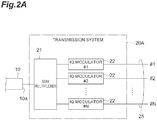
- a transmission system 20A in a conventional MDL measurement device corresponding to the transmission system 20 in Fig. 1A includes a Spatial-Division-Multiplexing (hereinafter referred to as "SDM") multiplexer 21, and N ( ⁇ 2) In-phase/Quadrature (IQ) modulators 22.
- the N IQ modulators 22 are provided respectively to N ( ⁇ 2) spatial channels #1 to #N in the optical fiber 10, and are controlled via control line (#1 to #N) 25 by the control device 40.
- the SDM multiplexer 21 inputs multiplexed light of modulated light from the N IQ modulators 22, from the input end 10a of the optical fiber 10 to the optical fiber 10.
- a reception system 30A in the conventional MDL measurement device corresponding to the reception system 30 in Fig. 1A includes an SDM splitter 31, and N coherent receivers 32 (coherent receivers #1 to #N) provided respectively to the spatial channels #1 to #N in the optical fiber 10.
- N coherent receivers 32 coherent receivers #1 to #N
- Light outputted from the output end 10b of the optical fiber 10 is split into light beams of the respective spatial channels by the SDM splitter 31, and complex amplitude information of light received by a corresponding coherent receiver 32 is measured.
- the control device 40 takes in the complex amplitude information of each of the spatial channels #1 to #N via control line 35, and the calculation means 50 calculates the MDL in the optical fiber 10.
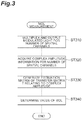
- a conventional MDL measurement method performs: multiplexing and outputting of the modulated light for the number of spatial channels (step ST310); acquisition of the complex amplitude information for the number of spatial channels (step ST320); generation of an estimation matrix of a transfer matrix T relating to the complex amplitude (step ST330); and determination of a value of the MDL (step ST340), and main operation of the method will be described below.
- step ST310 in the transmission system 20A, the IQ modulators 22 individually generate (modulate with a known pilot signal) the modulated light for each of the N spatial channels #1 to #N, and the multiplexed light multiplexed by the SDM multiplexer 21 is inputted from the input end 10a to the optical fiber 10.
- step ST320 the light outputted from the output end 10b of the optical fiber 10 is split by the SDM splitter 31, complex amplitude information of the light is acquired by the coherent receivers 32 provided respectively to the spatial channels #1 to #N, and the acquired complex amplitude information is sent to the control device 40 via the control line 35.
- step ST330 the calculation means 50 of the control device 40 uses the known pilot signal and the complex amplitude information of the light propagating through the optical fiber 10 as the measurement target, to calculate the estimation matrix of the transfer matrix T relating to the complex amplitude.
- calculation of the estimation matrix is performed by various methods such as Zero-Forcing estimation, least squares estimation, minimum norm solution, general/linear minimum mean square error estimation, maximum likelihood estimation, maximum ratio combining, subspace method, and compressed sensing.
- step ST340 the calculation means 50 performs singular decomposition of the calculated estimation matrix, and determines a ratio between the maximum value and the minimum value of squares of singular values, as an estimated value of the MDL.
- the present invention has been made to solve the above-described problem (necessity of performing complicated measurement and calculation), and it is an object of the present invention to provide a MDL measurement method and a MDL measurement device including a structure for enabling measurement of MDL of an optical fiber applied as a transmission line to a mode division multiplex transmission system without increasing a processing load, and an optical fiber applicable to the transmission medium for mode division multiplexing.
- a MDL (mode-dependent loss) measurement method measures MDL of an optical fiber as a measurement target, the optical fiber having a first end and a second end opposite to the first end and enabling optical transmission in N ( ⁇ 2) spatial modes between which a large mutual crosstalk occurs.
- the MDL measurement method executes generation of a transfer matrix relating to transmission loss in the optical fiber from the first end to the second end, and determination of a linear value of MDL per unit fiber length.
- the transfer matrix is obtained by repeating, for each of the N spatial modes while changing the target spatial mode, light-input operation and intensity measurement operation, the light-input operation inputting light of a predetermined intensity, from the first end of the optical fiber, to an arbitrary target spatial mode, the intensity measurement operation measuring intensity of light of each of the N spatial modes including the target spatial mode, the light being outputted from the second end of the optical fiber in response to light-input to the target spatial mode.
- the linear value of the MDL per unit fiber length is given by a ratio obtained by dividing the maximum value of matrix elements constituting the transfer matrix by the minimum value of the matrix elements, or a ratio obtained by dividing the maximum value of eigenvalues or singular values of the transfer matrix by the minimum value of the eigenvalues or the singular values. Further, a decibel value [dB/(unit fiber length) 1/2 ] of the MDL per unit fiber length may be determined by multiplying a common logarithm of the linear value by ten.
- the MDL of the transmission medium that is, the transmission loss difference between the spatial modes can be measured without coherent detection or calculation of a MIMO coefficient in mode division multiplex transmission.
- Fig. 1A is a diagram illustrating a schematic configuration of a general MDL measurement device in an optical fiber for mode division multiplex transmission.
- an input complex amplitude of N ( ⁇ 2) spatial channels (corresponding to N spatial modes) to the optical fiber is a column vector
- an output complex amplitude of the N spatial channels from the optical fiber is a column vector
- a transfer function of a transmission line including M pieces of time series or wavelength series information is a transfer matrix T of N rows and NM columns
- noise is n
- the state of light transmission in the optical fiber can be modeled as the expression (3) as follows:
- y ⁇ T
- the spatial mode in the optical fiber as the measurement target also includes a polarization mode.
- the spatial mode may be a spatial mode as a core mode of each core, or a spatial mode as an eigenmode of when a whole of a plurality of cores has a waveguide structure (super mode).
- a transfer matrix T of an actual optical fiber cannot be measured directly, so that the transfer matrix T is estimated from
- the above expression (3) can be thought of as N simultaneous expressions including (N ⁇ NM) variables in the transfer matrix T, so that the number of expressions is insufficient and the solution cannot be uniquely determined. For that reason, by using various methods (such as zero-forcing estimation, least squares estimation, minimum norm solution, general/linear minimum mean square error estimation, maximum likelihood estimation, maximum ratio combining, subspace method, and compressed sensing), a plausible solution (estimation matrix) is estimated as the transfer matrix T. Such calculation is not easy, and detection including phase information of light is necessary by using coherent receivers for the N spatial channels.
- MDL transmission loss difference between MIMO transmission channels
- MDL transmission loss difference between MIMO transmission channels
- a ratio between the maximum value and the minimum value of the squares of the singular values is obtained as an estimated value of the MDL (see Non Patent Document 2).
- This value is a linear value, which is usually represented in a decibel value by multiplying a common logarithm of the linear value by ten. If the transfer matrix T is not a predicted matrix but a true value, by singular value decomposition of the transfer matrix T into the form of the expression (5) below, the ratio between the maximum value and the minimum value of the squares of the singular values can be defined as the MDL.).
- T U ⁇ V * the matrices U and V* are unitary matrices of N rows and N columns, and NM rows and NM columns, respectively, and A is a matrix of N rows and NM columns in which a diagonal matrix of N rows and N columns whose diagonal components are singular values is included in the first part (a part including a matrix element (1, 1)) and the remaining matrix elements are zero.
- the transfer matrix ⁇ is considered to be an ensemble average of TT*.
- the matrix T* is an adjoint matrix of the matrix T.
- ⁇ x> represents an ensemble average of x
- ⁇ *> is a diagonal matrix whose diagonal components are ensemble averages of respective squares of absolute values of individual singular values. For that reason, a ratio obtained by dividing the maximum value of the diagonal elements of ⁇ *> by the minimum value corresponds to the linear value of the MDL.
- the above expression (7) corresponds to an expression of eigenvalue decomposition of the transfer matrix ⁇ , so that a matrix of N rows and N columns whose as diagonal elements are eigenvalues of the transfer matrix ⁇ is ⁇ *>.
- the transfer matrix ⁇ can be easily measured by the MDL measurement method of the present embodiment described above. However, if there is a measurement error, eigenvalue decomposition may not be possible.
- W* is a unitary matrix of N rows and N columns different from U.
- a ratio obtained by dividing the maximum value of elements of ⁇ *> by the minimum value may be determined as the MDL.
- a basic configuration of the MDL measurement device according to the present embodiment is similar to that of a general MDL measurement device 100 illustrated in Fig. 1A . That is, as illustrated in Fig. 1A , the MDL measurement device according to the present embodiment also includes a transmission system 20, a reception system 30, and a control device 40 including a calculation means 50.
- the control device 40 and the transmission system 20 are connected to each other via a transmission system control line (including a data line) 25, and the control device 40 and the reception system 30 are connected to each other via a reception system control line (including a data line) 35.
- a transmission system 20B in the MDL measurement device which corresponds to the transmission system 20 in Fig. 1A , includes an SDM multiplexer 21, a 1 ⁇ N optical switch 23, and a light source 24. ON/OFF of the light source 24 is controlled by the control device 40 via the control line 25.
- the control device 40 controls, via the control line 25, the 1 ⁇ N optical switch 23 to select a spatial mode as a target of light-input out of the N spatial modes (spatial channels) #1 to #N propagating in an optical fiber 10.
- light of the i-th spatial mode selected by the 1 ⁇ N optical switch 23 is inputted from an input end (first end) 10a via the SDM multiplexer 21 to the optical fiber 10.
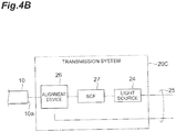
- a transmission system 20C in the MDL measurement device which corresponds to the transmission system 20 in Fig. 1A , includes an alignment device 26, a single core optical fiber (hereinafter referred to as "SCF") 27, and the light source 24.
- the alignment device 26 optically connects a specific core whose end face is positioned on the input end 10a of the optical fiber 10 as the measurement target, and the core of the SCF 27 to each other.
- the light source 24 is controlled from the control device 40 via the control line 25, and light outputted from the light source 24 is input into the core of the optical fiber 10 connected by the alignment device 26 via the SCF 27.
- a reception system 30B in the MDL measurement device which corresponds to the reception system 30 in Fig. 1A , includes an SDM splitter 31, and N power meters 33 (power meters #1 to #N) provided to correspond respectively to the N spatial modes #1 to #N propagating in the optical fiber 10.
- the SDM splitter 31 splits light outputted from an output end (second end) 10b of the optical fiber 10 into light beams of the N spatial modes #1 to #N, and each of the N power meters 33 measures light intensity of a corresponding spatial mode.
- the control device 40 takes in light intensity information of each of the spatial modes #1 to #N from corresponding one of the N power meters 33 via the control line 35.
- a reception system 30C in the MDL measurement device which corresponds to the reception system 30 in Fig. 1A , includes an alignment device 34, an SCF 36, and a power meter 37.
- the alignment device 34 optically connects a core positioned on the output end 10b of the optical fiber 10, and the core of the SCF 36 to each other, and sequentially guides, to the SCF 36, the light beams of the N spatial modes #1 to #N propagating in the optical fiber 10.
- the power meter 37 measures light intensity of each of the spatial modes reached via the SCF 36, and sequentially transmits measured light intensity information to the control device 40 via the control line 35.
- Fig. 6 is a flowchart for explaining the MDL measurement method according to the present embodiment. That is, the MDL measurement method according to the present embodiment executes identification of an unmeasured spatial mode (step ST610), measured light output to the identified spatial mode (step ST620), acquisition of a loss coefficient of all the spatial modes (step ST630), for all the spatial modes (step ST640). When steps ST610 to ST630 are completed for all the spatial modes, generation of the transfer matrix ⁇ relating to transmission loss of the optical fiber 10 (step ST650), and determination of a value of the MDL (step ST660) are executed. In the following description, Fig. 1A is appropriately referenced.
- step ST620 as the light-input operation, the transmission system 20B or 20C inputs the light of the intensity P i , from the input end (first end) 10a of the optical fiber 10 having the fiber length L i [unit fiber length], to the i-th spatial mode.
- step ST650 the calculation means 50 of the control device 40 generates the transfer matrix ⁇ given by the above expression (1).
- step ST660 the calculation means 50 of the control device 40 determines, as a linear value of the mode-dependent loss per unit fiber length, a ratio obtained by dividing the maximum value of matrix elements constituting the transfer matrix ⁇ by the minimum value of the matrix elements, or a ratio obtained by dividing the maximum value of eigenvalues or singular values of the transfer matrix ⁇ by the minimum value of the eigenvalues or the singular values, and determines the decibel value of the MDL [dB/(unit fiber length) 1/2 ] by multiplying the common logarithm of the obtained linear value by ten.
- the intensity is measured of the light of each of the N spatial modes in which the light intensity of the j-th spatial mode is represented by P ji [mW], the light being outputted from the output end 10b in response to the light-input to the i-th spatial mode.
- the cutback part is obtained having the input end 10a and the cutback length L i ' ( ⁇ L i ) [unit fiber length], obtained by cutting the optical fiber 10 at the position of 1 [m] to 50 [m] from the input end 10a while leaving the input end (first end) 10a.
- the light intensity P i ' [mW] is measured of the i-th spatial mode outputted from the output end (third end) 10c opposite to the input end 10a of the obtained cutback part.
- step ST660 the calculation means 50 of the control device 40 determines, as a linear value of the mode-dependent loss per unit fiber length, a ratio obtained by dividing the maximum value of matrix elements constituting the transfer matrix ⁇ by the minimum value of the matrix elements, or a ratio obtained by dividing the maximum value of eigenvalues or singular values of the transfer matrix ⁇ by the minimum value of the eigenvalues or the singular values, and determines the decibel value of the MDL [dB/(unit fiber length) 1/2 ] by multiplying the common logarithm of the obtained linear value by ten.
- the MDL in an optical fiber for mode division multiplex transmission in which crosstalk (hereinafter referred to as "XT") between the spatial modes is large that has been reported so far, that is, the MDL in a coupled MCF varies for each graph, but is approximately 0.06 dB/km 1/2 to 0.14 dB/km 1/2 .
- XT crosstalk
- the MDL measured by the MDL measurement method according to the present embodiment is preferably 0.02 dB/km 1/2 or less in the wavelength range of 1530 nm to 1565 nm or the wavelength range of 1460 nm to 1625 nm that are suitable for long distance transmission.
- the optical fiber for mode division multiplex transmission in which XT between spatial modes is large it is possible to maximize the capacity of a long distance transmission system using, as a transmission line, the optical fiber for mode division multiplex transmission in which XT between spatial modes is large.
- the MDL of the optical fiber 10 is preferably 0.01 dB/km 1/2 or less, further, 0.005 dB/km 1/2 or less, further 0.002 dB/km 1/2 or less, and further preferably 0.001 dB/km 1/2 or less.
- the average value of the MDL in the wavelength range of 1530 nm to 1565 nm or the wavelength range of 1460 nm to 1625 nm is 0.01 dB/km 1/2 or less, preferably 0.005 dB/km 1/2 or less, more preferably 0.002 dB/km 1/2 or less, and further preferably 0.001 dB/km 1/2 or less.
- the mode coupling coefficient is preferably 1 [m -1 ] to 100 [m -1 ] at the wavelength of 1550 nm.
- the transmission loss at all mode excitation is preferably 0.020 dB/km or less, more preferably 0.018 dB/km or less, further 0.16 dB/km or less, and further preferably 0.15 dB/km or less in the wavelength range of 1530 nm to 1565 nm or the wavelength range of 1460 nm to 1625 nm.
- the mode average of chromatic dispersion is preferably 16 ps/(nm ⁇ km) or more.
- the effective area A eff of the spatial mode localized in each core is preferably 75 ⁇ m 2 to 180 ⁇ m 2 in all the spatial modes.
- the bending loss is preferably 0.2 dB or less when the optical fiber is wound one turn around the mandrel having the diameter of 30 mm.
- bending loss at a diameter of 20 mm is preferably 20 dB/m or less.
- bending loss is preferably 0.5 dB or less when the optical fiber is wound 100 turns around a mandrel having a radius of 30 mm.
- the optical fiber 10 preferably has an average value of 10 ps/km 1/2 or less, 1 ps/km 1/2 or less, or 0.1 ps/km 1/2 or less, when the maximum value of the inter-mode DGD is measured at each wavelength over the wavelength range of 1530 nm to 1565 nm or the wavelength range of 1460 nm to 1625 nm.
- the same number of spatial modes as the number of cores included in the optical fiber are set as propagation modes in descending order of effective refractive indexes.
- transmission loss of a spatial mode having the highest effective refractive index out of spatial modes excluding the propagation modes is preferably greater than the transmission loss of each of the propagation modes by 19.3 dB or more, regardless of a bending state of the optical fiber.
- the optical fiber 10 includes a coupled MCF including a plurality of cores 11, a common optical cladding 12a covering all of the plurality of cores 11, and a physical cladding 12b covering the common optical cladding 12a.
- the optical cladding 12a is a part of a cladding 12 contributing to optical transmission
- the physical cladding 12b is a part of the cladding 12 not contributing to optical transmission.
- a cladding diameter of the optical fiber 10 is desirably 124 ⁇ m to 126 ⁇ m.
- a covering diameter of the optical fiber 10 is desirably 240 ⁇ m to 260 ⁇ m.
- 10 Optical fiber (measurement target); 20, 20B, 20C ... Transmission system; 25 ... Transmission system control line; 30, 30B, 30C ... Reception system; 35 ... Reception system control line (including data line); 40 ... Control device; 50 ... Calculation means; and 100 ... MDL measurement device.
Landscapes
- Physics & Mathematics (AREA)
- General Physics & Mathematics (AREA)
- Optics & Photonics (AREA)
- Chemical & Material Sciences (AREA)
- Dispersion Chemistry (AREA)
- Analytical Chemistry (AREA)
- Optical Communication System (AREA)
- Testing Of Optical Devices Or Fibers (AREA)
- Optical Fibers, Optical Fiber Cores, And Optical Fiber Bundles (AREA)
Applications Claiming Priority (2)
| Application Number | Priority Date | Filing Date | Title |
|---|---|---|---|
| JP2016042209A JP6790383B2 (ja) | 2016-03-04 | 2016-03-04 | モード依存損失測定方法および測定装置 |
| PCT/JP2016/088146 WO2017149910A1 (fr) | 2016-03-04 | 2016-12-21 | Procédé de mesure et dispositif de mesure de perte dépendante du mode |
Publications (2)
| Publication Number | Publication Date |
|---|---|
| EP3425367A1 true EP3425367A1 (fr) | 2019-01-09 |
| EP3425367A4 EP3425367A4 (fr) | 2019-06-19 |
Family
ID=59743675
Family Applications (1)
| Application Number | Title | Priority Date | Filing Date |
|---|---|---|---|
| EP16892744.0A Withdrawn EP3425367A4 (fr) | 2016-03-04 | 2016-12-21 | Procédé de mesure et dispositif de mesure de perte dépendante du mode |
Country Status (5)
| Country | Link |
|---|---|
| US (1) | US11022523B2 (fr) |
| EP (1) | EP3425367A4 (fr) |
| JP (1) | JP6790383B2 (fr) |
| CN (1) | CN107923816B (fr) |
| WO (1) | WO2017149910A1 (fr) |
Cited By (1)
| Publication number | Priority date | Publication date | Assignee | Title |
|---|---|---|---|---|
| WO2022035630A1 (fr) * | 2020-08-10 | 2022-02-17 | Corning Incorporated | Fibres optiques multicoeurs à coeurs couplés à très faible perte |
Families Citing this family (21)
| Publication number | Priority date | Publication date | Assignee | Title |
|---|---|---|---|---|
| US10345192B2 (en) * | 2017-03-14 | 2019-07-09 | Nokia Of America Corporation | Single-end optical fiber transfer matrix measurement using spatial pilot |
| JP6846024B2 (ja) * | 2017-09-21 | 2021-03-24 | Kddi株式会社 | モード多重光信号の測定装置、光受信装置及びプログラム |
| JP6814121B2 (ja) * | 2017-09-29 | 2021-01-13 | Kddi株式会社 | モード多重光通信システムの光受信装置及びプログラム |
| WO2020171187A1 (fr) * | 2019-02-22 | 2020-08-27 | 住友電気工業株式会社 | Dispositif et procédé de mesure de perte dépendant du mode |
| CN110673337B (zh) * | 2019-09-27 | 2021-08-24 | 南开大学 | 一种多芯波导传输特性的快速矢量分析方法 |
| CN112232503B (zh) * | 2020-06-09 | 2021-11-19 | 联合微电子中心有限责任公司 | 计算装置、计算方法以及计算系统 |
| CN114079486B (zh) * | 2020-08-21 | 2024-11-12 | 中兴通讯股份有限公司 | 空分复用光纤的特征参数监测方法、装置、设备和存储介质 |
| JP2022042131A (ja) * | 2020-09-02 | 2022-03-14 | 住友電気工業株式会社 | 面発光レーザの測定方法、製造方法、測定装置、および測定プログラム |
| JP7424510B2 (ja) * | 2020-11-10 | 2024-01-30 | 日本電信電話株式会社 | 空間多重光伝送路の特性を評価する装置及び方法 |
| US20220380694A1 (en) * | 2021-05-27 | 2022-12-01 | Lance Patrick McDermott | Cannabis Waste Cooking Fuel and Animal Feed Pellets |
| JP7542808B2 (ja) * | 2021-08-16 | 2024-09-02 | 日本電信電話株式会社 | マルチモード伝送システム |
| JP7763415B2 (ja) * | 2021-10-07 | 2025-11-04 | Ntt株式会社 | マルチモードファイバのモード依存損失算出装置及びモード依存損失算出方法 |
| JP7828602B2 (ja) * | 2022-01-31 | 2026-03-12 | 国立研究開発法人情報通信研究機構 | モード分散補償用情報の取得方法及び装置 |
| JP2025516392A (ja) * | 2022-04-21 | 2025-05-28 | アドバンスド マイクロ ファウンドリー ピーティーイー.リミテッド | 波長経路分割によるウェハレベル試験における光損失の測定方法及びシステム |
| CN114813062A (zh) * | 2022-06-30 | 2022-07-29 | 武汉锐科光纤激光技术股份有限公司 | 激光器用光器件的损耗测试系统 |
| JP7852411B2 (ja) * | 2022-07-11 | 2026-04-28 | 住友電気工業株式会社 | モード依存損失測定装置、およびモード依存損失測定方法 |
| CN116399457B (zh) * | 2022-12-30 | 2025-08-22 | 长沙大科光剑科技有限公司 | 一种少模光纤激光器光束质量测量的方法 |
| WO2024166574A1 (fr) * | 2023-02-09 | 2024-08-15 | 株式会社フジクラ | Fibre multicoeur pour communication, et dispositif de communication optique |
| CN117824996A (zh) * | 2023-12-07 | 2024-04-05 | 广东工业大学 | 一种模式相关损耗的测量系统及测量方法 |
| WO2025173489A1 (fr) * | 2024-02-14 | 2025-08-21 | 住友電気工業株式会社 | Dispositif et procédé de mesure |
| WO2025173488A1 (fr) * | 2024-02-14 | 2025-08-21 | 住友電気工業株式会社 | Dispositif de fibres optiques |
Family Cites Families (12)
| Publication number | Priority date | Publication date | Assignee | Title |
|---|---|---|---|---|
| DE60231378D1 (de) * | 2002-10-11 | 2009-04-16 | Agilent Technologies Inc | Bestimmung der Modenspektren für die Hauptzustände der Polarisation |
| US7126679B2 (en) * | 2002-10-30 | 2006-10-24 | Advantest Corporation | Device method and program for measuring polarization mode dispersion and recording medium recording the program |
| US20050063712A1 (en) * | 2003-09-22 | 2005-03-24 | Rice Robert R. | High speed large core multimode fiber optic transmission system and method therefore |
| US7633607B2 (en) * | 2004-09-01 | 2009-12-15 | Luna Innovations Incorporated | Method and apparatus for calibrating measurement equipment |
| FR2951282B1 (fr) * | 2009-10-13 | 2012-06-15 | Draka Comteq France | Fibre optique monomode a tranchee enterree |
| WO2012161811A1 (fr) * | 2011-02-24 | 2012-11-29 | Ofs Fitel, Llc | Conceptions de fibre multicœur pour multiplexage spatial |
| DK2584388T3 (en) * | 2011-10-20 | 2018-12-03 | Draka Comteq Bv | Method for calculating an effective bandwidth of a multimode fiber |
| US8873954B2 (en) * | 2012-02-01 | 2014-10-28 | Ramot At Tel-Aviv University Ltd. | System and method for exchanging information over a jacobi MIMO channel |
| WO2013161825A1 (fr) * | 2012-04-26 | 2013-10-31 | 住友電気工業株式会社 | Fibre optique multicœur, câble de fibre optique multicœur et système d'émission à fibre optique multicœur |
| US9197356B2 (en) * | 2012-11-16 | 2015-11-24 | At&T Intellectual Property I, L.P. | Distributed spatial mode processing for spatial-mode multiplexed communication systems |
| US9442246B2 (en) * | 2013-10-14 | 2016-09-13 | Futurewei Technologies, Inc. | System and method for optical fiber |
| US10901240B2 (en) * | 2016-02-04 | 2021-01-26 | Massachusetts Institute Of Technology | Electro-Optic beam controller and method |
-
2016
- 2016-03-04 JP JP2016042209A patent/JP6790383B2/ja active Active
- 2016-12-21 WO PCT/JP2016/088146 patent/WO2017149910A1/fr not_active Ceased
- 2016-12-21 CN CN201680050174.6A patent/CN107923816B/zh active Active
- 2016-12-21 EP EP16892744.0A patent/EP3425367A4/fr not_active Withdrawn
-
2018
- 2018-03-16 US US15/923,062 patent/US11022523B2/en active Active
Cited By (3)
| Publication number | Priority date | Publication date | Assignee | Title |
|---|---|---|---|---|
| WO2022035630A1 (fr) * | 2020-08-10 | 2022-02-17 | Corning Incorporated | Fibres optiques multicoeurs à coeurs couplés à très faible perte |
| US11733449B2 (en) | 2020-08-10 | 2023-08-22 | Corning Incorporated | Ultra-low-loss coupled-core multicore optical fibers |
| US12050339B2 (en) | 2020-08-10 | 2024-07-30 | Corning Incorporated | Ultra-low-loss coupled-core multicore optical fibers |
Also Published As
| Publication number | Publication date |
|---|---|
| JP6790383B2 (ja) | 2020-11-25 |
| US20180202895A1 (en) | 2018-07-19 |
| CN107923816A (zh) | 2018-04-17 |
| US11022523B2 (en) | 2021-06-01 |
| EP3425367A4 (fr) | 2019-06-19 |
| JP2017156308A (ja) | 2017-09-07 |
| CN107923816B (zh) | 2021-07-06 |
| WO2017149910A1 (fr) | 2017-09-08 |
Similar Documents
| Publication | Publication Date | Title |
|---|---|---|
| US11022523B2 (en) | Mode-dependent loss measurement method and measurement device | |
| US10845268B1 (en) | Monitorable hollow core optical fiber | |
| US11754466B2 (en) | Mode-dependent loss measurement device and mode-dependent loss measuring method | |
| US11719599B2 (en) | Optical fiber test method and optical fiber test device | |
| US8965217B2 (en) | Superimposing optical transmission modes | |
| EP3623789B1 (fr) | Procédé de mesure de non-linéarité et dispositif de mesure de non-linéarité | |
| JP6897373B2 (ja) | 光ファイバ出射ビームプロファイル測定方法および装置 | |
| JP2014153116A (ja) | マルチモード光ファイバ用モード結合測定装置 | |
| CN103067084A (zh) | 对多模光纤的给定比特错误率的功率损失进行评估的方法 | |
| US20050018174A1 (en) | Apparatus and method for measuring characteristics of iptical fibers | |
| CN114303327A (zh) | 光纤测量系统、将通信光纤适配到测量系统中的方法以及光纤测量和通信系统 | |
| Cappelletti et al. | Statistical analysis of modal dispersion in field-installed coupled-core fiber link | |
| JP7497780B2 (ja) | 光ファイバ試験方法及び光ファイバ試験装置 | |
| EP3391008B1 (fr) | Procédé de qualification de fibre multimode à large bande à partir d'une caractérisation en longueur d'onde unique par extrapolation emb, système et programme d'ordinateur correspondants | |
| Xiong et al. | Study on characteristics of coupled-core four-core fibers with different core pitches | |
| JP2023094677A (ja) | 空間モード分散測定装置および測定方法 | |
| Rademacher et al. | Time-dependent inter-core crosstalk between multiple cores of a homogeneous multi-core fiber | |
| Antonelli et al. | Near-zero modal-dispersion (NEMO) coupled-core multi-core fibers | |
| US20240344928A1 (en) | Device, method and system for calculating power coupling coefficients between cores | |
| Swain et al. | Evaluation of mode division multiplexed system by dynamic power transfer matrix characterization | |
| Cappelletti | Innovative Characterization Methods for Next Generation Optical Fibers. | |
| Hossain et al. | BER performance limitations due to inter-core crosstalk in a multi-core fiber-optic transmission system | |
| Takahashi et al. | Distributed measurement of single-way inter-modal crosstalk in spliced FMFs based on BOTDA | |
| Dadras et al. | Characterization of fiber modal impairments using direct-detection methods | |
| Sandmann et al. | Mode Group Power Coupling Analysis for Short Reach Space Division Multiplexing |
Legal Events
| Date | Code | Title | Description |
|---|---|---|---|
| STAA | Information on the status of an ep patent application or granted ep patent |
Free format text: STATUS: THE INTERNATIONAL PUBLICATION HAS BEEN MADE |
|
| PUAI | Public reference made under article 153(3) epc to a published international application that has entered the european phase |
Free format text: ORIGINAL CODE: 0009012 |
|
| STAA | Information on the status of an ep patent application or granted ep patent |
Free format text: STATUS: REQUEST FOR EXAMINATION WAS MADE |
|
| 17P | Request for examination filed |
Effective date: 20180322 |
|
| AK | Designated contracting states |
Kind code of ref document: A1 Designated state(s): AL AT BE BG CH CY CZ DE DK EE ES FI FR GB GR HR HU IE IS IT LI LT LU LV MC MK MT NL NO PL PT RO RS SE SI SK SM TR |
|
| AX | Request for extension of the european patent |
Extension state: BA ME |
|
| RIC1 | Information provided on ipc code assigned before grant |
Ipc: G02B 6/02 20060101AFI20190211BHEP Ipc: G01M 11/00 20060101ALI20190211BHEP |
|
| DAV | Request for validation of the european patent (deleted) | ||
| DAX | Request for extension of the european patent (deleted) | ||
| A4 | Supplementary search report drawn up and despatched |
Effective date: 20190520 |
|
| RIC1 | Information provided on ipc code assigned before grant |
Ipc: G02B 6/02 20060101AFI20190514BHEP Ipc: G01M 11/00 20060101ALI20190514BHEP |
|
| STAA | Information on the status of an ep patent application or granted ep patent |
Free format text: STATUS: EXAMINATION IS IN PROGRESS |
|
| 17Q | First examination report despatched |
Effective date: 20200407 |
|
| STAA | Information on the status of an ep patent application or granted ep patent |
Free format text: STATUS: THE APPLICATION IS DEEMED TO BE WITHDRAWN |
|
| 18D | Application deemed to be withdrawn |
Effective date: 20210504 |