EP3425384A1 - Piège à ions multipolaire pour spectrométrie de masse - Google Patents
Piège à ions multipolaire pour spectrométrie de masse Download PDFInfo
- Publication number
- EP3425384A1 EP3425384A1 EP18183824.4A EP18183824A EP3425384A1 EP 3425384 A1 EP3425384 A1 EP 3425384A1 EP 18183824 A EP18183824 A EP 18183824A EP 3425384 A1 EP3425384 A1 EP 3425384A1
- Authority
- EP
- European Patent Office
- Prior art keywords
- electrodes
- ions
- ion
- mass
- containment region
- Prior art date
- Legal status (The legal status is an assumption and is not a legal conclusion. Google has not performed a legal analysis and makes no representation as to the accuracy of the status listed.)
- Granted
Links
- 0 CC(*(C1)CC2)C(CC3)(C4C5C3CC3C6)C1C2C1C4C5=C3C6C1 Chemical compound CC(*(C1)CC2)C(CC3)(C4C5C3CC3C6)C1C2C1C4C5=C3C6C1 0.000 description 1
Images



Classifications
-
- H—ELECTRICITY
- H01—ELECTRIC ELEMENTS
- H01J—ELECTRIC DISCHARGE TUBES OR DISCHARGE LAMPS
- H01J49/00—Particle spectrometers or separator tubes
- H01J49/26—Mass spectrometers or separator tubes
- H01J49/34—Dynamic spectrometers
- H01J49/42—Stability-of-path spectrometers, e.g. monopole, quadrupole, multipole, farvitrons
- H01J49/4205—Device types
-
- H—ELECTRICITY
- H01—ELECTRIC ELEMENTS
- H01J—ELECTRIC DISCHARGE TUBES OR DISCHARGE LAMPS
- H01J49/00—Particle spectrometers or separator tubes
- H01J49/02—Details
- H01J49/06—Electron- or ion-optical arrangements
-
- H—ELECTRICITY
- H01—ELECTRIC ELEMENTS
- H01J—ELECTRIC DISCHARGE TUBES OR DISCHARGE LAMPS
- H01J49/00—Particle spectrometers or separator tubes
- H01J49/02—Details
-
- H—ELECTRICITY
- H01—ELECTRIC ELEMENTS
- H01J—ELECTRIC DISCHARGE TUBES OR DISCHARGE LAMPS
- H01J49/00—Particle spectrometers or separator tubes
- H01J49/26—Mass spectrometers or separator tubes
- H01J49/34—Dynamic spectrometers
- H01J49/36—Radio frequency spectrometers, e.g. Bennett-type spectrometers, Redhead-type spectrometers
-
- H—ELECTRICITY
- H01—ELECTRIC ELEMENTS
- H01J—ELECTRIC DISCHARGE TUBES OR DISCHARGE LAMPS
- H01J49/00—Particle spectrometers or separator tubes
- H01J49/26—Mass spectrometers or separator tubes
- H01J49/34—Dynamic spectrometers
- H01J49/42—Stability-of-path spectrometers, e.g. monopole, quadrupole, multipole, farvitrons
- H01J49/4205—Device types
- H01J49/422—Two-dimensional RF ion traps
- H01J49/4225—Multipole linear ion traps, e.g. quadrupoles, hexapoles
-
- H—ELECTRICITY
- H01—ELECTRIC ELEMENTS
- H01J—ELECTRIC DISCHARGE TUBES OR DISCHARGE LAMPS
- H01J49/00—Particle spectrometers or separator tubes
- H01J49/26—Mass spectrometers or separator tubes
- H01J49/34—Dynamic spectrometers
- H01J49/42—Stability-of-path spectrometers, e.g. monopole, quadrupole, multipole, farvitrons
- H01J49/4205—Device types
- H01J49/424—Three-dimensional ion traps, i.e. comprising end-cap and ring electrodes
Definitions
- the present disclosure relates to ion traps and, in particular, to a multi-pole ion trap device for efficient and high capacity storage of ions and parallel mass selective ion ejection.
- Ion trap mass spectrometers have conventionally operated with a three-dimensional (3D) quadrupole field formed, for example, using a ring electrode and two end caps.
- 3D three-dimensional
- RF radio-frequency
- quadrupole mass spectrometers having a two-dimensional quadrupole electric field were introduced in order to expand the ion storage area from a small sphere into an extended cylindrical column.
- An example of this type of spectrometer is provided in U.S. Patent 5,420,425 to Bier, et al.
- the Bier, et al. patent discloses a substantially quadrupole ion trap mass spectrometer with an enlarged or elongated ion occupied volume.
- the ion trap has a space charge limit that is proportional to the length of the device. After collision relaxation, ions occupy an extended region coinciding with the axis of the device.
- patent discloses a two-dimensional ion trap, which can be straight, or of a circular or curved shape, and also an ellipsoidal three-dimensional ion trap with increased ion trapping capacity. Ions are mass-selectively ejected from the ion trap through an elongated aperture corresponding to the elongated storage area.
- the efficiency and versatility of the mass spectrometer suffer, for example, due to the elongated slit and subsequent focusing of the ions required after ejection.
- the storage volume is limited by practical considerations, since the length of the spectrometer must be increased in order to increase the ion storage volume.
- the disclosure is directed to a high-capacity and versatile ion trap device.
- the ion trap device includes a containment region for containing ions, and a regular polyhedral structure including a plurality of electrodes encompassing the containment region, wherein the containment region for containing ions corresponds substantially to a volume encompassed by the regular polyhedral structure.
- the ion trap further includes a plurality of vertices, and a plurality of regular polygonal surfaces which define the regular polyhedral structure.
- the plurality of electrodes includes a vertex electrode positioned on each vertex of the plurality of vertices, at least four of the vertex electrodes being positioned on a first surface of the plurality of regular polygonal surfaces.
- the plurality of electrodes preferably also includes additional electrodes on the first surface, which are configured to form a plurality of quadrupoles on the first surface.
- a first RF voltage is applied to alternating electrodes of the plurality of electrodes, and a second RF voltage is applied to electrodes interspersed between the alternating electrodes, the first and second RF voltage being of equal amplitude and opposite polarity at a point in time, so that directly neighboring electrodes of the plurality of electrodes are maintained at opposite phases.
- This configuration of the plurality of electrodes with alternating RF phase forms a potential barrier for repelling the ions in the containment region from each of the regular polygonal surfaces forming the regular polyhedral structure.
- the disclosure is also directed to an efficient parallel mass spectrometer including an ion trap device formed in accordance with the disclosure.
- the parallel mass spectrometer includes: an ion source generating ions, a plurality of mass analyzers, and an ion trap device coupled to receive ions exiting the ion source and to eject ions to the plurality of mass analyzers in a mass-charge dependent manner.
- the ion trap further includes a containment region for containing the ions received from the ion source and a regular polyhedral structure including a plurality of electrodes encompassing the containment region, wherein the containment region for containing the ions corresponds substantially to a volume encompassed by the regular polyhedral structure.
- a plurality of vertices and a plurality of regular polygonal surfaces defines the regular polyhedral structure.
- the plurality of electrodes includes a vertex electrode positioned on each vertex of the plurality of vertices, at least four of the vertex electrodes being positioned on a first surface of the plurality of regular polygonal surfaces.
- the plurality of electrodes preferably also includes a set of electrodes configured to form a plurality of quadrupoles on the first surface.
- a first RF voltage is applied to alternating electrodes of the plurality of electrodes, and a second RF voltage is applied to electrodes interspersed between the alternating electrodes, the first and second RF voltage being of equal amplitude and opposite polarity at a point in time, neighboring electrodes of the plurality of electrodes being maintained at opposite phases.
- the plurality of electrodes with alternating RF phase are configured to form a potential barrier for repelling the ions from each of the plurality of regular polygonal surfaces forming the regular polyhedral structure.
- each of the plurality of quadrupoles on the first surface is configured as a mass filter for selective ejection of the ions from the containment region in a predetermined ion mass-to-charge window.
- a frequency of the first RF and the second RF voltage applied to the electrodes in each of the plurality of quadrupoles corresponds to a characteristic frequency associated with the predetermined ion mass-to-charge window.
- Each of the plurality of quadrupoles is preferably coupled to a different one of the plurality of mass analyzers for parallel analysis.
- the disclosure is also directed to an ion trap device including a containment region for containing ions; a regular polyhedral structure comprising a plurality of electrodes encompassing the containment region, wherein the containment region corresponds substantially to a volume encompassed by the regular polyhedral structure; a plurality of vertices and a plurality of regular polygonal surfaces and edges defining the regular polyhedral structure; the plurality of electrodes including an edge electrode positioned along each edge of the plurality of regular polygonal structures, and at least one additional electrode positioned on each of the plurality of regular polygonal surfaces; and a first RF voltage applied to each of the edge electrodes, and a second RF voltage applied to each of the at least one additional electrodes, the first and second RF voltage being of equal amplitude and opposite polarity at a point in time, the at least one additional electrode and the edge electrode associated with each surface being adjacent electrodes, the adjacent electrodes being maintained at opposite phases, wherein the plurality of electrodes are configured to form
- each of the plurality of electrodes in an ion trap of the present disclosure can be one of a cylindrical rod or a sphere.
- electrodes can be edge electrodes that follow the outline or edges of the polygonal surfaces associated with the polyhedral structure.
- the electrodes of alternating phase can be in the form of nested annuli structures, which can be, for example, triangular, rhombic, square, hex or any other shape corresponding to the shape of a face of a polyhedron.
- edge electrodes can alternate in phase with additional electrodes positioned on the surfaces, or faces of the regular polyhedral structure.
- the additional electrodes can be a single electrode, which can be a sphere, centered on each face of the regular polyhedral structure.
- the regular polyhedral structure of the ion trap can be in the shape of a cube, tetrahedron, octahedron, icosahedron, or dodecahedron.
- the structure of an ion trap device of the present disclosure is a cube, and includes a total of N 3 - (N-2) 3 electrodes and N 3 - (N-2) 3 - 2 quadrupoles, wherein N represents an integer preferably greater than 2.
- a volume of the containment region of a cubic ion trap device of the present disclosure is about 10 cm x 10 cm x 10 cm, the ion trap device having an ion capacity of greater than 10 10 ions.
- the ion trap device of the present disclosure can be configured as a collision cell, an ion-ion reactor, a molecule-ion reactor, or a photon-ion reactor.
- a plate electrode is positioned outside each of the surfaces of the regular polyhedral structure, and a first DC voltage sufficient to prevent depletion of ions from the containment region is applied at least to a first plate electrode.
- a second DC stopping voltage that is lower than the first DC stopping voltage is applied to a second plate electrode positioned outside another one of the surfaces, the second DC stopping voltage generating a potential barrier sufficiently high to prevent depletion of multiple charged ions and sufficiently low to deplete singly charged ions from the containment region.
- the second plate electrode is positioned outside one of the surfaces of the regular polyhedral structure which includes a plurality of quadrupoles. The depletion of the singly charged ions is preferably amplified by providing multiple channels, or axes, associated with the plurality of quadrupoles, for the depletion of the singly charged ions from the containment region.
- An ion trap device of the present disclosure is a multi-pole ion trap, which includes a plurality of electrodes positioned around an ion confinement region, preferably in a regular pattern.
- the plurality of electrodes are preferably confined to the surface area, or faces, of a regular polyhedron and are positioned on at least the vertices of the regular polyhedral structure.
- the plurality of electrodes also includes additional electrodes arranged along the edges and between the edges in a regular pattern on the surfaces or faces of the polyhedron.
- these arrangements of electrodes on a polyhedral structure provide surfaces with a high electric potential, which will repel and contain ions within an ion containment region bounded by the polyhedral structure. Accordingly, the containment volume for storage of ions corresponds substantially to the volume encompassed by the surface area of the polyhedron.
- the ion traps of the present disclosure can, therefore, offer very high ion capacity, not offered by conventional quadrupole systems.
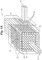
- an ion trap in the form of a cube of dimensions 10 cm x 10 cm x 10 cm an example of which is provided in FIG. 1A
- Kerchinsky the disclosure of which is incorporated herein by reference, and 10 5 -10 6 times higher than that of current commercial linear ion traps commonly used as mass analyzers for analyzing molecules (excluding large storage ring accelerators used in nuclear physics).
- a regular polyhedral structure in the form of a cube encloses an ion containment region54.
- a plurality of electrodes 52 which are in the shape of cylindrical rods, are positioned on a surface area of the cube in a regular pattern, the cylindrical electrodes 52 being positioned at the eight vertices of the cube and also between the vertices in each dimension such that there are N x N electrodes positioned on each surface.
- the number of electrodes N equals 8.
- N is greater than 2.
- Quadrupoles are commonly known for use as ion guides and/or mass filters.
- Each pair of adjacent rods in a quadrupole is connected to a positive or a negative RF potential of suitable magnitude and frequency for the particular application, so that direct neighbors are maintained at opposing polarities or phases with the same amplitude.
- This arrangement is known to provide radial confinement of ions around a central axis of the rod set forming the quadrupole. Referring to FIG.
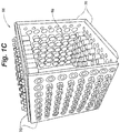
- FIG. 1C shows a partially assembled ion trap device 66 with two of its surfaces removed, clearly showing a large hollow ion containment region 68.
- a regular two-dimensional array of rod-shaped electrodes is positioned and oriented to provide an array of quadrupoles on each surface.
- an ion trap device of the present disclosure can also include plate electrodes 56 outside the surfaces 70 of the regular polyhedral structure of the device.
- a small DC potential can be applied to any number of the plate electrodes to repel the ions back towards the containment region 60.
- a DC voltage is applied in the range of between about 0 V and about +1000 V, preferably in the range of between about +0.02 V to about +100 V to at least a portion of the plate electrodes to prevent, for example, positive ions from escaping.
- any of the plate electrodes 56 can include ports 58 to allow ions to be injected into the ion containment region 54, and/or for ejecting ions out of the ion containment region 54.
- the two-dimensional array of rod-shaped electrodes on one of the surfaces of the cube can include a quadrupole ion guide 72 to guide ions into a containment volume and/or a quadrupole ion guide 74 to guide ions out of the containment volume.
- the quadrupoles for ion guiding and mass filtering are formed from sets of extended rods.
- parameters such as the length of the extended rods, and the voltage and frequency of the RF signal applied to the rods of the quadrupole ion guides 72, 74 can be appropriately adjusted for ion guiding and/or for mass filtering for a particular mass-to-charge window. Accordingly, ions can be ejected in a mass-to-charge dependent manner through a port 58 in a plate electrode 56, for example, appropriately positioned to coincide with the region centered along the axis of the quadrupole 74.
- mass selective ion ejection can be achieved along the axis of the quadrupole 74.
- the ion device can include a large number of quadrupoles.
- an extended rod set of quadrupoles 76 can be provided and used for parallel analysis of the mass-to-charge values of a large range of ions stored in the trap.
- mass selective ion ejection from the device can be performed periodically or continuously along any or all of the N 3 -(N-2) 3 -2 quadrupole axes.
- a parallel mass spectrometer of the present disclosure can include up to N 3 -(N-2) 3 -2 individual mass analyzers, one for each mass-to-charge window of ions ejected from each quadrupole for simultaneous parallel analysis of the ions stored in the device.
- Highly efficient parallel mass spectrometry free of losses associated with conventional sequential ion scanning can therefore be provided by implementing the ion device of the present disclosure.
- Electrodes shown in FIG. 1A and 1C are cylindrical rods, any appropriately shaped electrode is contemplated to be within the scope of the present invention.
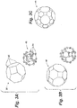
- the electrodes can be spherical, cylindrical, cubic, hyperbolic or various shaped annuli, as shown in FIGS. 3D and 3E (circular, triangular, square, and so on).
- the electrodes can have a diameter between about 1 mm and 20 mm, preferably between about 5 mm and 10 mm.
- a center-to-center distance between the electrodes aligned on a surface of the polyhedral structure can be between about 1.25D and about 1.75D, where D is a diameter of the electrodes aligned on the surface.
- the center-to-center distance can be about 1.2D to 1.5D.
- a surface structure encompassing the ion containment region have been discovered to be surprisingly high efficiency ion traps. While the surface structure of the present disclosure can be generally described as a regular polyhedral structure, having alternating RF-phased electrodes positioned at least at the vertices, it was found that superior results can be achieved with cube structures including both electrodes positioned at the vertices and additional electrodes positioned at regular intervals between the vertices. Preferred structures also include higher-order regular polyhedral structures.
- a multi-pole ion trap of the present disclosure can include a plurality of electrodes positioned around an ion confinement region in a regular pattern provided by higher-order regular polyhedrons. While a cube is one of the simplest forms of a regular, or uniform, polyhedral structure, on which the plurality of electrodes are positioned, other forms are also contemplated.
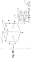
- electrodes 84 can be positioned at the vertices 85 of a tetrahedral structure 86, and an RF voltage applied with alternating polarity as shown.
- additional electrodes could also be positioned in two-dimensional arrays on any one or more of the surfaces of the structure 86.
- an octahedral structure 88 is another embodiment of a polyhedral structure suitable for enclosing an ion containment region of an ion trap of the present disclosure.
- an octahedral structure 88 By placing 24 electrodes at each vertex of the (4,6,6)-octahedron 88 and applying RF voltage with alternating polarity to adjacent electrodes, six (6) quadrupoles and eight (8) hexapoles are formed on the surfaces encompassing the ion containment region.
- higher-order regular polyhedrons such as icosahedral structures 90 are contemplated to be within the scope of the invention.
- suitable higher order 3D multi-poles will include an even number of electrodes on each side of the polyhedral structure.
- an embodiment of a 3D multi-pole 150 can be also constructed by using the edges and the sides (faces) of a polyhedron by placing alternating annular electrodes 152, 154 outlining the shape of each of the polyhedron faces, and arranged in a nested pattern.
- alternating annular electrodes 152, 154 outlining the shape of each of the polyhedron faces, and arranged in a nested pattern.
- square annular electrodes of diminishing size are placed on all 6 sides of the cube, and an alternating potential as shown is applied to the alternating pairs. This approach can be extended to any regular polyhedron.
- yet another embodiment of a 3D multi-pole 160 can be constructed from a plurality of electrodes including multiple electrodes outlining the edges 164 of a polyhedron, with additional electrodes 162 of opposite polarity as the outlined edges 164 on its faces.
- a dodecahedron shaped 3D multipole is built by applying alternating RF potentials of opposite polarity to the electrode edges 164 (-U 0 sin ⁇ t) and to spherical electrodes 162 (+U 0 sin ⁇ t) positioned on the centers of the 12 dodecahydron faces.
- FIG. 4 indicates that the ion devices of the present disclosure can be used as very efficient ion beam splitters. Furthermore, the more electrodes that are used to build the trap, the larger are the number of quadrupoles through which ions can escape. One important consequence of this result is that if each quadrupole is configured to selectively transmit or eject a narrow m/z window, then m/z analysis can be performed in parallel.
- a 17x17x17 ion trap device (built from 17 3 -15 3 or 1538 electrodes) can provide parallel analysis for mass spectrometry of all ions stored in the ion trap in a m/z range of about 1500 (the range currently used for ESI mass spectrometry) with 1 m/z wide windows.
- This provides an instrument that is potentially 1000-fold more efficient than current commercial mass spectrometers that sequentially select narrow m/z windows while rejecting, and, therefore, wasting, the rest of the ions during the analysis.
- ions can be prevented from escaping along the quadrupole axes by applying an appropriate DC potential to the plate electrodes 56 encompassing the trap. Under these conditions, ions can be stored in the trap for a long time, during which time they occupy essentially the entire inside ion containment volume.
- an ion trap device of the present disclosure of dimensions 100mm x 100mm x 100mm is expected to have a capacity of ⁇ 3x10 10 ions.
- An ion trap device formed in accordance with the present disclosure can also be used as an efficient device for real-time enrichment of multiply charged ions, by creating conditions for very efficient selective depletion of singly-charged ions.
- the potential barrier can be sufficiently reduced to allow singly charged ions to escape preferentially over multiply-charged ions.
- FIG. 5 an embodiment of a cubic ion trap having 296 rod electrodes is shown, which includes at least two plate electrodes 95 maintained at a DC potential (e.g., +10V) sufficient to contain ions in the ion containment volume. If the same potential is applied to each of the plates, ions can be contained in the trap for a long period of time, for example, on the order of seconds to minutes. However, if the DC trapping voltage is reduced on one or more of the plate electrodes 96 to a sufficiently small value, e.g., ⁇ +0.03V, singly charged ions will escape through this small potential barrier, but not multiply-charged ions.
- a sufficiently small value e.g., ⁇ +0.03V
- the singly-charged ions will quickly "evaporate" from the trap providing an opportunity for real time enrichment of the multiply-charged ions that enter and leave the trap.
- the rate of singly charged ions evaporation can be amplified by increasing the number of plates maintained at the small stopping potential, and by increasing the number of channels 98.
- Such a device in which a simple setting of a single voltage would efficiently remove all singly charged ions from the ion beam has the potential to become a potent tool for improving the signal-to-noise of MS analyses and for the highly desired discriminating reduction of the number of ions in the beam without throwing out information.
- a mass spectrometry system of the present disclosure includes an embodiment of the ion trap.
- the multiple quadrupoles of the ion trap can be used as mass filters, each having a different m/z window for conditioning the ion beam for analysis.
- a parallel mass spectrometer is provided which includes anion trap device of the present disclosure for performing parallel analysis of all ions in the enclosure (cube).
- the ion trap is adapted to selectively enrich multiply-charged ions in real-time through depletion of singly-charged ions as they pass through the ion trap.
- a parallel mass spectrometer 100 includes an embodiment of an ion trap 110 in accordance with the present disclosure, with multiple parallel outputs 115 of ions in multiple m/z windows.
- the mass spectrometer can include a plurality of mass analyzers 120 for parallel mass analysis, with each mass analyzer coupled to a different output port 115.
- the ion trap 110 which in this particular embodiment includes 296 cylindrical rod electrodes, can be coupled to any appropriate ion source 122, such as an electrospray ionization source (ESI), or an appropriate Matrix-Assisted Laser Desorption-Ionization (MALDI) source.
- ESI electrospray ionization source
- MALDI Matrix-Assisted Laser Desorption-Ionization
- the mass spectrometer 100 can also include other elements known in the art such as a collimation device 124 for coupling ions from the ion source 122 into the ion trap 110.
- ions are coupled into an ion containment region 126 through a port 128 in one 130 of the six electrode plates that surround the cubic ion structure encompassing the containment region 126.
- additional input ports can be provided to couple to additional ion or other sources.
- the plate electrode 130 is preferably biased with a high DC voltage (e.g., about +10V) for containment of the injected ions in the containment region 126.
- Additional plates 132 can be biased at a small DC voltage, e.g ., about +0.03V, for depletion of singly-charged ions. As discussed herein below, depletion of these singly-charged ions provides a mass spectrometer characterized by a high signal-to-noise ratio.
- Mass selective ion ejection from embodiments of the ion trap device with multiple mass filtered outputs, such as the device 110, can be performed periodically or continuously along any or all of the N 3 -(N-2) 3 -2 quadrupole axes.
- the mass selective ion ejection, or filtering can be performed according to methods known in the art, such as by mass resonance ion ejection, or using resonance ion injection into each quadrupole axis(channel) by supplying wide band resonance excitation containing all frequencies that excite all ions in the trap except the ions characterized by a particular m/z. These ions pass through the quadrupole to be detected at the exit using multiple ion detectors, or using a large array detector, such as a CCD, or in the case of analysis of chemical and biological assays, a "soft-landed" species device.
- a collision cell includes an ion trap device of the present disclosure.
- the ion containment region of the collision cell includes an appropriate buffer gas and mass filters are formed from quadrupoles on the surface of the polyhedral structure to accelerated ions from a narrow m/z window into the containment region.
- the ion trap device of the present disclosure is configured as an ion-ion, molecule-ion or photon-ion reactor.
- the effect of selective depletion of singly charged ions was simulated for a multi-quadrupole ion trap of the present disclosure, as described in reference to FIG. 5 , for example, built from 296 quadrupoles.
Landscapes
- Chemical & Material Sciences (AREA)
- Analytical Chemistry (AREA)
- Electron Tubes For Measurement (AREA)
- Other Investigation Or Analysis Of Materials By Electrical Means (AREA)
Applications Claiming Priority (3)
| Application Number | Priority Date | Filing Date | Title |
|---|---|---|---|
| US13/782,708 US8637817B1 (en) | 2013-03-01 | 2013-03-01 | Multi-pole ion trap for mass spectrometry |
| PCT/US2014/018330 WO2014134043A2 (fr) | 2013-03-01 | 2014-02-25 | Piège ionique multipolaire pour spectrométrie de masse |
| EP14756573.3A EP2962094B1 (fr) | 2013-03-01 | 2014-02-25 | Piège ionique multipolaire pour spectrométrie de masse |
Related Parent Applications (2)
| Application Number | Title | Priority Date | Filing Date |
|---|---|---|---|
| EP14756573.3A Division EP2962094B1 (fr) | 2013-03-01 | 2014-02-25 | Piège ionique multipolaire pour spectrométrie de masse |
| EP14756573.3A Division-Into EP2962094B1 (fr) | 2013-03-01 | 2014-02-25 | Piège ionique multipolaire pour spectrométrie de masse |
Publications (2)
| Publication Number | Publication Date |
|---|---|
| EP3425384A1 true EP3425384A1 (fr) | 2019-01-09 |
| EP3425384B1 EP3425384B1 (fr) | 2021-12-22 |
Family
ID=49957928
Family Applications (2)
| Application Number | Title | Priority Date | Filing Date |
|---|---|---|---|
| EP18183824.4A Active EP3425384B1 (fr) | 2013-03-01 | 2014-02-25 | Piège à ions multipolaire pour spectrométrie de masse |
| EP14756573.3A Active EP2962094B1 (fr) | 2013-03-01 | 2014-02-25 | Piège ionique multipolaire pour spectrométrie de masse |
Family Applications After (1)
| Application Number | Title | Priority Date | Filing Date |
|---|---|---|---|
| EP14756573.3A Active EP2962094B1 (fr) | 2013-03-01 | 2014-02-25 | Piège ionique multipolaire pour spectrométrie de masse |
Country Status (4)
| Country | Link |
|---|---|
| US (4) | US8637817B1 (fr) |
| EP (2) | EP3425384B1 (fr) |
| ES (1) | ES2690044T3 (fr) |
| WO (1) | WO2014134043A2 (fr) |
Families Citing this family (41)
| Publication number | Priority date | Publication date | Assignee | Title |
|---|---|---|---|---|
| US9136128B2 (en) | 2011-08-31 | 2015-09-15 | Micron Technology, Inc. | Methods and apparatuses including memory cells with air gaps and other low dielectric constant materials |
| US8637817B1 (en) | 2013-03-01 | 2014-01-28 | The Rockefeller University | Multi-pole ion trap for mass spectrometry |
| WO2017132444A1 (fr) * | 2016-01-28 | 2017-08-03 | Purdue Research Foundation | Systèmes et procédés de séparation d'ions à une pression environ égale ou supérieure à la pression atmosphérique |
| US10224194B2 (en) * | 2016-09-08 | 2019-03-05 | Battelle Memorial Institute | Device to manipulate ions of same or different polarities |
| WO2018087634A1 (fr) * | 2016-11-11 | 2018-05-17 | Dh Technologies Development Pte. Ltd. | Procédé et dispositif d'injection d'ions à focalisation spatiale, massique et énergétique |
| US10680006B2 (en) | 2017-08-11 | 2020-06-09 | Micron Technology, Inc. | Charge trap structure with barrier to blocking region |
| US10446572B2 (en) | 2017-08-11 | 2019-10-15 | Micron Technology, Inc. | Void formation for charge trap structures |
| US10164009B1 (en) | 2017-08-11 | 2018-12-25 | Micron Technology, Inc. | Memory device including voids between control gates |
| US10453855B2 (en) * | 2017-08-11 | 2019-10-22 | Micron Technology, Inc. | Void formation in charge trap structures |
| US10332723B1 (en) | 2017-12-20 | 2019-06-25 | Battelle Memorial Institute | Ion focusing device |
| US11219393B2 (en) | 2018-07-12 | 2022-01-11 | Trace Matters Scientific Llc | Mass spectrometry system and method for analyzing biological samples |
| EP3814762A4 (fr) * | 2018-06-05 | 2022-03-23 | The Rockefeller University | Spectromètre de masse à temps de vol à faisceaux multiples parallèles |
| US10720315B2 (en) | 2018-06-05 | 2020-07-21 | Trace Matters Scientific Llc | Reconfigurable sequentially-packed ion (SPION) transfer device |
| US12089932B2 (en) | 2018-06-05 | 2024-09-17 | Trace Matters Scientific Llc | Apparatus, system, and method for transferring ions |
| US10840077B2 (en) | 2018-06-05 | 2020-11-17 | Trace Matters Scientific Llc | Reconfigureable sequentially-packed ion (SPION) transfer device |
| US10460920B1 (en) | 2018-06-26 | 2019-10-29 | Battelle Memorial Institute | Flexible ion conduit |
| DE102018116308A1 (de) | 2018-07-05 | 2020-01-09 | Analytik Jena Ag | Dynamische Ionenfilterung zur Reduzierung hochabundanter Ionen |
| JP2021534560A (ja) * | 2018-08-24 | 2021-12-09 | ディーエイチ テクノロジーズ デベロップメント プライベート リミテッド | 汚染を低減させ、質量分析法システムのロバスト性を向上させるためのrf/dcカットオフ |
| CN113301875B (zh) | 2019-01-23 | 2022-12-09 | 宝洁公司 | 适于隐蔽携带和取用的包装女性卫生护垫产品及制造方法 |
| CN113613606B (zh) | 2019-02-13 | 2023-01-17 | 宝洁公司 | 具有增强的皮肤感觉的带有非织造顶片的女性卫生护垫 |
| EP3923882B1 (fr) | 2019-02-13 | 2024-10-23 | The Procter & Gamble Company | Serviette hygiénique féminine avec feuille supérieure hydrophile non tissée offrant une meilleure sensation sur la peau et des performances de dissimulation |
| WO2021022547A1 (fr) | 2019-08-08 | 2021-02-11 | The Procter & Gamble Company | Protection hygiénique féminine et méthode pour isoler des micro-organismes de la peau d'un utilisateur |
| US11561148B2 (en) * | 2019-11-08 | 2023-01-24 | IonQ, Inc. | Techniques for measuring collision rate with spatial filtering of scattered light |
| EP4171669B1 (fr) | 2020-06-26 | 2024-12-11 | The Procter & Gamble Company | Articles absorbants comprenant une mousse hipe renforcée avec des nanoplaquettes d'argile, et procédé de fabrication |
| WO2023205193A1 (fr) | 2022-04-22 | 2023-10-26 | The Procter & Gamble Company | Article absorbant conformable au corps |
| US20230381034A1 (en) | 2022-05-25 | 2023-11-30 | The Procter & Gamble Company | Absorbent article |
| US20230381036A1 (en) | 2022-05-25 | 2023-11-30 | The Procter & Gamble Company | Absorbent article for fluid management |
| EP4531780A1 (fr) | 2022-05-25 | 2025-04-09 | The Procter & Gamble Company | Procédé d'emballage d'un article absorbant |
| CN119451654A (zh) | 2022-05-25 | 2025-02-14 | 宝洁公司 | 具有适形特征部的吸收制品 |
| US20240115436A1 (en) | 2022-10-10 | 2024-04-11 | The Procter & Gamble Company | Feminine hygiene pad with foam absorbent and reservoir spacer layer |
| US20240156647A1 (en) | 2022-11-14 | 2024-05-16 | The Procter & Gamble Company | Body-conformable absorbent article |
| EP4683601A1 (fr) | 2023-03-21 | 2026-01-28 | The Procter & Gamble Company | Article absorbant emballé dans une matière comprenant des fibres naturelles |
| WO2024243007A1 (fr) | 2023-05-19 | 2024-11-28 | The Procter & Gamble Company | Serviette hygiénique féminine avec couche absorbante en mousse et conformité corporelle améliorée |
| US20250057705A1 (en) | 2023-08-14 | 2025-02-20 | The Procter & Gamble Company | Absorbent article with absorbent core structure having a shaped inner core layer |
| CN121712475A (zh) | 2023-08-14 | 2026-03-20 | 宝洁公司 | 包括具有成形内芯层的吸收芯结构的吸收制品 |
| WO2025038681A1 (fr) | 2023-08-14 | 2025-02-20 | The Procter & Gamble Company | Article absorbant à structure d'âme absorbante avec couche d'âme interne façonnée |
| US20250057703A1 (en) | 2023-08-14 | 2025-02-20 | The Procter & Gamble Company | Absorbent article with absorbent core structure having a shaped inner core layer |
| US20250161120A1 (en) | 2023-11-20 | 2025-05-22 | The Procter & Gamble Company | Absorbent articles with short cellulosic fiber |
| US20250161123A1 (en) | 2023-11-20 | 2025-05-22 | The Procter & Gamble Company | Absorbent products having improved packaging efficiency |
| US20250352409A1 (en) | 2024-05-14 | 2025-11-20 | The Procter & Gamble Company | Body-conformable absorbent articles with an elastic backsheet |
| US20260102535A1 (en) | 2024-10-16 | 2026-04-16 | The Procter & Gamble Company | Absorbent articles including hipe foam imparted with color, and method of manufacture |
Citations (4)
| Publication number | Priority date | Publication date | Assignee | Title |
|---|---|---|---|---|
| US5420425A (en) | 1994-05-27 | 1995-05-30 | Finnigan Corporation | Ion trap mass spectrometer system and method |
| US20050258364A1 (en) * | 2004-05-21 | 2005-11-24 | Whitehouse Craig M | RF surfaces and RF ion guides |
| US7323683B2 (en) | 2005-08-31 | 2008-01-29 | The Rockefeller University | Linear ion trap for mass spectrometry |
| EP2058837A2 (fr) * | 2007-11-09 | 2009-05-13 | Microsaic Systems Limited | Structures d'électrodes |
Family Cites Families (8)
| Publication number | Priority date | Publication date | Assignee | Title |
|---|---|---|---|---|
| DE19523859C2 (de) | 1995-06-30 | 2000-04-27 | Bruker Daltonik Gmbh | Vorrichtung für die Reflektion geladener Teilchen |
| US6838666B2 (en) * | 2003-01-10 | 2005-01-04 | Purdue Research Foundation | Rectilinear ion trap and mass analyzer system and method |
| GB0426900D0 (en) * | 2004-12-08 | 2005-01-12 | Micromass Ltd | Mass spectrometer |
| US7217922B2 (en) * | 2005-03-14 | 2007-05-15 | Lucent Technologies Inc. | Planar micro-miniature ion trap devices |
| US7358488B2 (en) | 2005-09-12 | 2008-04-15 | Mds Inc. | Mass spectrometer multiple device interface for parallel configuration of multiple devices |
| JP4905270B2 (ja) * | 2007-06-29 | 2012-03-28 | 株式会社日立製作所 | イオントラップ、質量分析計、イオンモビリティ分析計 |
| WO2012005561A2 (fr) * | 2010-07-09 | 2012-01-12 | Saparqaliyev Aldan Asanovich | Procédé de spectrométrie de masse et dispositif de sa mise en oeuvre |
| US8637817B1 (en) * | 2013-03-01 | 2014-01-28 | The Rockefeller University | Multi-pole ion trap for mass spectrometry |
-
2013
- 2013-03-01 US US13/782,708 patent/US8637817B1/en active Active
- 2013-12-20 US US14/136,132 patent/US8866076B2/en active Active
-
2014
- 2014-02-25 ES ES14756573.3T patent/ES2690044T3/es active Active
- 2014-02-25 EP EP18183824.4A patent/EP3425384B1/fr active Active
- 2014-02-25 WO PCT/US2014/018330 patent/WO2014134043A2/fr not_active Ceased
- 2014-02-25 EP EP14756573.3A patent/EP2962094B1/fr active Active
- 2014-09-23 US US14/493,776 patent/US9129789B2/en active Active
-
2015
- 2015-09-08 US US14/847,565 patent/US9299550B2/en active Active
Patent Citations (4)
| Publication number | Priority date | Publication date | Assignee | Title |
|---|---|---|---|---|
| US5420425A (en) | 1994-05-27 | 1995-05-30 | Finnigan Corporation | Ion trap mass spectrometer system and method |
| US20050258364A1 (en) * | 2004-05-21 | 2005-11-24 | Whitehouse Craig M | RF surfaces and RF ion guides |
| US7323683B2 (en) | 2005-08-31 | 2008-01-29 | The Rockefeller University | Linear ion trap for mass spectrometry |
| EP2058837A2 (fr) * | 2007-11-09 | 2009-05-13 | Microsaic Systems Limited | Structures d'électrodes |
Non-Patent Citations (1)
| Title |
|---|
| PEARSON C E ET AL: "Experimental investigation of planar ion traps", ARXIV.ORG, CORNELL UNIVERSITY LIBRARY, 201 OLIN LIBRARY CORNELL UNIVERSITY ITHACA, NY 14853, 3 November 2005 (2005-11-03), XP080214093, DOI: 10.1103/PHYSREVA.73.032307 * |
Also Published As
| Publication number | Publication date |
|---|---|
| WO2014134043A2 (fr) | 2014-09-04 |
| US20160005579A1 (en) | 2016-01-07 |
| EP2962094A2 (fr) | 2016-01-06 |
| US9299550B2 (en) | 2016-03-29 |
| US8866076B2 (en) | 2014-10-21 |
| WO2014134043A3 (fr) | 2015-06-25 |
| EP3425384B1 (fr) | 2021-12-22 |
| ES2690044T3 (es) | 2018-11-19 |
| EP2962094B1 (fr) | 2018-09-05 |
| EP2962094A4 (fr) | 2016-10-12 |
| US8637817B1 (en) | 2014-01-28 |
| US20150041640A1 (en) | 2015-02-12 |
| US9129789B2 (en) | 2015-09-08 |
| US20140246582A1 (en) | 2014-09-04 |
Similar Documents
| Publication | Publication Date | Title |
|---|---|---|
| EP2962094B1 (fr) | Piège ionique multipolaire pour spectrométrie de masse | |
| EP1704578B1 (fr) | Dispositifs d'extraction d'ions et procedes d'extraction selective d'ions | |
| US7405401B2 (en) | Ion extraction devices, mass spectrometer devices, and methods of selectively extracting ions and performing mass spectrometry | |
| US8637816B1 (en) | Systems and methods for MS-MS-analysis | |
| US6838666B2 (en) | Rectilinear ion trap and mass analyzer system and method | |
| US7595486B2 (en) | RF multipole ion guides for broad mass range | |
| CN1910727B (zh) | 将离子捕获到多极离子阱的方法及多极离子阱装置 | |
| JP6495192B2 (ja) | トロイダルトラップ構造のパルスイオン源 | |
| JP2009506515A (ja) | 質量分析のための新しい線形イオントラップ | |
| CN101369510A (zh) | 环形管状电极离子阱 | |
| WO2007130303A1 (fr) | Réseaux d'électrodes pour pièges à ions parallèles | |
| EP1806765A2 (fr) | Augmentation de l'énergie cinétique d'ions le long de l'axe de dispositifs linéaires de traitement d'ions | |
| DE102011109927A1 (de) | Einführung von Ionen in Kingdon-Ionenfallen | |
| CN1788327A (zh) | 直线式离子阱及质量分析器系统和方法 | |
| US7180057B1 (en) | Two-dimensional quadrupole ion trap | |
| EP2534670B1 (fr) | Système électrode de piège ionique linéaire | |
| CN105513938A (zh) | 一种梯形体电极线形离子阱 | |
| US20220367163A1 (en) | Parallel multi-beam time-of-flight mass spectrometer | |
| US9536723B1 (en) | Thin field terminator for linear quadrupole ion guides, and related systems and methods | |
| Mamatova | Influence of an ion trap geometry on its trapping efficiency | |
| Gill | The ion conveyor: an ion focussing and conveying device for mass spectrometry | |
| Salazar et al. | Computer simulation of the gap-tripole ion trap with linear injection, 3D ion accumulation, and versatile packet ejection | |
| Door | Fragmentation of leucine-enkephalin by collision induced dissociation for different keV projectile ions |
Legal Events
| Date | Code | Title | Description |
|---|---|---|---|
| PUAI | Public reference made under article 153(3) epc to a published international application that has entered the european phase |
Free format text: ORIGINAL CODE: 0009012 |
|
| STAA | Information on the status of an ep patent application or granted ep patent |
Free format text: STATUS: REQUEST FOR EXAMINATION WAS MADE |
|
| 17P | Request for examination filed |
Effective date: 20180717 |
|
| AC | Divisional application: reference to earlier application |
Ref document number: 2962094 Country of ref document: EP Kind code of ref document: P |
|
| AK | Designated contracting states |
Kind code of ref document: A1 Designated state(s): AL AT BE BG CH CY CZ DE DK EE ES FI FR GB GR HR HU IE IS IT LI LT LU LV MC MK MT NL NO PL PT RO RS SE SI SK SM TR |
|
| RIN1 | Information on inventor provided before grant (corrected) |
Inventor name: COHEN, HERBERT Inventor name: KRUTCHINSKY, ANDREW N. Inventor name: SHERMAN, VADIM Inventor name: CHAIT, BRIAN T. |
|
| GRAP | Despatch of communication of intention to grant a patent |
Free format text: ORIGINAL CODE: EPIDOSNIGR1 |
|
| STAA | Information on the status of an ep patent application or granted ep patent |
Free format text: STATUS: GRANT OF PATENT IS INTENDED |
|
| INTG | Intention to grant announced |
Effective date: 20210728 |
|
| GRAS | Grant fee paid |
Free format text: ORIGINAL CODE: EPIDOSNIGR3 |
|
| GRAA | (expected) grant |
Free format text: ORIGINAL CODE: 0009210 |
|
| STAA | Information on the status of an ep patent application or granted ep patent |
Free format text: STATUS: THE PATENT HAS BEEN GRANTED |
|
| AC | Divisional application: reference to earlier application |
Ref document number: 2962094 Country of ref document: EP Kind code of ref document: P |
|
| AK | Designated contracting states |
Kind code of ref document: B1 Designated state(s): AL AT BE BG CH CY CZ DE DK EE ES FI FR GB GR HR HU IE IS IT LI LT LU LV MC MK MT NL NO PL PT RO RS SE SI SK SM TR |
|
| REG | Reference to a national code |
Ref country code: GB Ref legal event code: FG4D |
|
| REG | Reference to a national code |
Ref country code: CH Ref legal event code: EP |
|
| REG | Reference to a national code |
Ref country code: DE Ref legal event code: R096 Ref document number: 602014081871 Country of ref document: DE |
|
| REG | Reference to a national code |
Ref country code: AT Ref legal event code: REF Ref document number: 1457390 Country of ref document: AT Kind code of ref document: T Effective date: 20220115 |
|
| REG | Reference to a national code |
Ref country code: IE Ref legal event code: FG4D |
|
| REG | Reference to a national code |
Ref country code: LT Ref legal event code: MG9D |
|
| PG25 | Lapsed in a contracting state [announced via postgrant information from national office to epo] |
Ref country code: RS Free format text: LAPSE BECAUSE OF FAILURE TO SUBMIT A TRANSLATION OF THE DESCRIPTION OR TO PAY THE FEE WITHIN THE PRESCRIBED TIME-LIMIT Effective date: 20211222 Ref country code: LT Free format text: LAPSE BECAUSE OF FAILURE TO SUBMIT A TRANSLATION OF THE DESCRIPTION OR TO PAY THE FEE WITHIN THE PRESCRIBED TIME-LIMIT Effective date: 20211222 Ref country code: FI Free format text: LAPSE BECAUSE OF FAILURE TO SUBMIT A TRANSLATION OF THE DESCRIPTION OR TO PAY THE FEE WITHIN THE PRESCRIBED TIME-LIMIT Effective date: 20211222 Ref country code: BG Free format text: LAPSE BECAUSE OF FAILURE TO SUBMIT A TRANSLATION OF THE DESCRIPTION OR TO PAY THE FEE WITHIN THE PRESCRIBED TIME-LIMIT Effective date: 20220322 |
|
| REG | Reference to a national code |
Ref country code: NL Ref legal event code: MP Effective date: 20211222 |
|
| PG25 | Lapsed in a contracting state [announced via postgrant information from national office to epo] |
Ref country code: SE Free format text: LAPSE BECAUSE OF FAILURE TO SUBMIT A TRANSLATION OF THE DESCRIPTION OR TO PAY THE FEE WITHIN THE PRESCRIBED TIME-LIMIT Effective date: 20211222 Ref country code: NO Free format text: LAPSE BECAUSE OF FAILURE TO SUBMIT A TRANSLATION OF THE DESCRIPTION OR TO PAY THE FEE WITHIN THE PRESCRIBED TIME-LIMIT Effective date: 20220322 Ref country code: LV Free format text: LAPSE BECAUSE OF FAILURE TO SUBMIT A TRANSLATION OF THE DESCRIPTION OR TO PAY THE FEE WITHIN THE PRESCRIBED TIME-LIMIT Effective date: 20211222 Ref country code: HR Free format text: LAPSE BECAUSE OF FAILURE TO SUBMIT A TRANSLATION OF THE DESCRIPTION OR TO PAY THE FEE WITHIN THE PRESCRIBED TIME-LIMIT Effective date: 20211222 Ref country code: GR Free format text: LAPSE BECAUSE OF FAILURE TO SUBMIT A TRANSLATION OF THE DESCRIPTION OR TO PAY THE FEE WITHIN THE PRESCRIBED TIME-LIMIT Effective date: 20220323 |
|
| PG25 | Lapsed in a contracting state [announced via postgrant information from national office to epo] |
Ref country code: NL Free format text: LAPSE BECAUSE OF FAILURE TO SUBMIT A TRANSLATION OF THE DESCRIPTION OR TO PAY THE FEE WITHIN THE PRESCRIBED TIME-LIMIT Effective date: 20211222 |
|
| PG25 | Lapsed in a contracting state [announced via postgrant information from national office to epo] |
Ref country code: SM Free format text: LAPSE BECAUSE OF FAILURE TO SUBMIT A TRANSLATION OF THE DESCRIPTION OR TO PAY THE FEE WITHIN THE PRESCRIBED TIME-LIMIT Effective date: 20211222 Ref country code: SK Free format text: LAPSE BECAUSE OF FAILURE TO SUBMIT A TRANSLATION OF THE DESCRIPTION OR TO PAY THE FEE WITHIN THE PRESCRIBED TIME-LIMIT Effective date: 20211222 Ref country code: RO Free format text: LAPSE BECAUSE OF FAILURE TO SUBMIT A TRANSLATION OF THE DESCRIPTION OR TO PAY THE FEE WITHIN THE PRESCRIBED TIME-LIMIT Effective date: 20211222 Ref country code: PT Free format text: LAPSE BECAUSE OF FAILURE TO SUBMIT A TRANSLATION OF THE DESCRIPTION OR TO PAY THE FEE WITHIN THE PRESCRIBED TIME-LIMIT Effective date: 20220422 Ref country code: ES Free format text: LAPSE BECAUSE OF FAILURE TO SUBMIT A TRANSLATION OF THE DESCRIPTION OR TO PAY THE FEE WITHIN THE PRESCRIBED TIME-LIMIT Effective date: 20211222 Ref country code: EE Free format text: LAPSE BECAUSE OF FAILURE TO SUBMIT A TRANSLATION OF THE DESCRIPTION OR TO PAY THE FEE WITHIN THE PRESCRIBED TIME-LIMIT Effective date: 20211222 Ref country code: CZ Free format text: LAPSE BECAUSE OF FAILURE TO SUBMIT A TRANSLATION OF THE DESCRIPTION OR TO PAY THE FEE WITHIN THE PRESCRIBED TIME-LIMIT Effective date: 20211222 |
|
| PG25 | Lapsed in a contracting state [announced via postgrant information from national office to epo] |
Ref country code: PL Free format text: LAPSE BECAUSE OF FAILURE TO SUBMIT A TRANSLATION OF THE DESCRIPTION OR TO PAY THE FEE WITHIN THE PRESCRIBED TIME-LIMIT Effective date: 20211222 |
|
| REG | Reference to a national code |
Ref country code: DE Ref legal event code: R097 Ref document number: 602014081871 Country of ref document: DE |
|
| PG25 | Lapsed in a contracting state [announced via postgrant information from national office to epo] |
Ref country code: MC Free format text: LAPSE BECAUSE OF FAILURE TO SUBMIT A TRANSLATION OF THE DESCRIPTION OR TO PAY THE FEE WITHIN THE PRESCRIBED TIME-LIMIT Effective date: 20211222 Ref country code: IS Free format text: LAPSE BECAUSE OF FAILURE TO SUBMIT A TRANSLATION OF THE DESCRIPTION OR TO PAY THE FEE WITHIN THE PRESCRIBED TIME-LIMIT Effective date: 20220422 |
|
| REG | Reference to a national code |
Ref country code: BE Ref legal event code: MM Effective date: 20220228 |
|
| PLBE | No opposition filed within time limit |
Free format text: ORIGINAL CODE: 0009261 |
|
| STAA | Information on the status of an ep patent application or granted ep patent |
Free format text: STATUS: NO OPPOSITION FILED WITHIN TIME LIMIT |
|
| PG25 | Lapsed in a contracting state [announced via postgrant information from national office to epo] |
Ref country code: LU Free format text: LAPSE BECAUSE OF NON-PAYMENT OF DUE FEES Effective date: 20220225 Ref country code: DK Free format text: LAPSE BECAUSE OF FAILURE TO SUBMIT A TRANSLATION OF THE DESCRIPTION OR TO PAY THE FEE WITHIN THE PRESCRIBED TIME-LIMIT Effective date: 20211222 Ref country code: AL Free format text: LAPSE BECAUSE OF FAILURE TO SUBMIT A TRANSLATION OF THE DESCRIPTION OR TO PAY THE FEE WITHIN THE PRESCRIBED TIME-LIMIT Effective date: 20211222 |
|
| 26N | No opposition filed |
Effective date: 20220923 |
|
| PG25 | Lapsed in a contracting state [announced via postgrant information from national office to epo] |
Ref country code: IE Free format text: LAPSE BECAUSE OF NON-PAYMENT OF DUE FEES Effective date: 20220225 |
|
| PG25 | Lapsed in a contracting state [announced via postgrant information from national office to epo] |
Ref country code: SI Free format text: LAPSE BECAUSE OF FAILURE TO SUBMIT A TRANSLATION OF THE DESCRIPTION OR TO PAY THE FEE WITHIN THE PRESCRIBED TIME-LIMIT Effective date: 20211222 Ref country code: BE Free format text: LAPSE BECAUSE OF NON-PAYMENT OF DUE FEES Effective date: 20220228 |
|
| PGFP | Annual fee paid to national office [announced via postgrant information from national office to epo] |
Ref country code: CH Payment date: 20230307 Year of fee payment: 10 Ref country code: AT Payment date: 20230221 Year of fee payment: 10 |
|
| PG25 | Lapsed in a contracting state [announced via postgrant information from national office to epo] |
Ref country code: IT Free format text: LAPSE BECAUSE OF FAILURE TO SUBMIT A TRANSLATION OF THE DESCRIPTION OR TO PAY THE FEE WITHIN THE PRESCRIBED TIME-LIMIT Effective date: 20211222 |
|
| P01 | Opt-out of the competence of the unified patent court (upc) registered |
Effective date: 20230525 |
|
| REG | Reference to a national code |
Ref country code: AT Ref legal event code: UEP Ref document number: 1457390 Country of ref document: AT Kind code of ref document: T Effective date: 20211222 |
|
| PG25 | Lapsed in a contracting state [announced via postgrant information from national office to epo] |
Ref country code: HU Free format text: LAPSE BECAUSE OF FAILURE TO SUBMIT A TRANSLATION OF THE DESCRIPTION OR TO PAY THE FEE WITHIN THE PRESCRIBED TIME-LIMIT; INVALID AB INITIO Effective date: 20140225 |
|
| PG25 | Lapsed in a contracting state [announced via postgrant information from national office to epo] |
Ref country code: MK Free format text: LAPSE BECAUSE OF FAILURE TO SUBMIT A TRANSLATION OF THE DESCRIPTION OR TO PAY THE FEE WITHIN THE PRESCRIBED TIME-LIMIT Effective date: 20211222 Ref country code: CY Free format text: LAPSE BECAUSE OF FAILURE TO SUBMIT A TRANSLATION OF THE DESCRIPTION OR TO PAY THE FEE WITHIN THE PRESCRIBED TIME-LIMIT Effective date: 20211222 |
|
| PG25 | Lapsed in a contracting state [announced via postgrant information from national office to epo] |
Ref country code: TR Free format text: LAPSE BECAUSE OF FAILURE TO SUBMIT A TRANSLATION OF THE DESCRIPTION OR TO PAY THE FEE WITHIN THE PRESCRIBED TIME-LIMIT Effective date: 20211222 |
|
| PG25 | Lapsed in a contracting state [announced via postgrant information from national office to epo] |
Ref country code: MT Free format text: LAPSE BECAUSE OF FAILURE TO SUBMIT A TRANSLATION OF THE DESCRIPTION OR TO PAY THE FEE WITHIN THE PRESCRIBED TIME-LIMIT Effective date: 20211222 |
|
| REG | Reference to a national code |
Ref country code: CH Ref legal event code: PL |
|
| REG | Reference to a national code |
Ref country code: AT Ref legal event code: MM01 Ref document number: 1457390 Country of ref document: AT Kind code of ref document: T Effective date: 20240225 |
|
| PG25 | Lapsed in a contracting state [announced via postgrant information from national office to epo] |
Ref country code: CH Free format text: LAPSE BECAUSE OF NON-PAYMENT OF DUE FEES Effective date: 20240229 |
|
| PG25 | Lapsed in a contracting state [announced via postgrant information from national office to epo] |
Ref country code: AT Free format text: LAPSE BECAUSE OF NON-PAYMENT OF DUE FEES Effective date: 20240225 |
|
| PG25 | Lapsed in a contracting state [announced via postgrant information from national office to epo] |
Ref country code: CH Free format text: LAPSE BECAUSE OF NON-PAYMENT OF DUE FEES Effective date: 20240229 Ref country code: AT Free format text: LAPSE BECAUSE OF NON-PAYMENT OF DUE FEES Effective date: 20240225 |
|
| PGFP | Annual fee paid to national office [announced via postgrant information from national office to epo] |
Ref country code: GB Payment date: 20260227 Year of fee payment: 13 |
|
| PGFP | Annual fee paid to national office [announced via postgrant information from national office to epo] |
Ref country code: DE Payment date: 20260227 Year of fee payment: 13 |
|
| PGFP | Annual fee paid to national office [announced via postgrant information from national office to epo] |
Ref country code: FR Payment date: 20260225 Year of fee payment: 13 |