EP3425794B1 - Least-mean-squares-anpassung eines simultanen mehrbandigen vorverzerrers mit überlappenden splines - Google Patents
Least-mean-squares-anpassung eines simultanen mehrbandigen vorverzerrers mit überlappenden splines Download PDFInfo
- Publication number
- EP3425794B1 EP3425794B1 EP18184909.2A EP18184909A EP3425794B1 EP 3425794 B1 EP3425794 B1 EP 3425794B1 EP 18184909 A EP18184909 A EP 18184909A EP 3425794 B1 EP3425794 B1 EP 3425794B1
- Authority
- EP
- European Patent Office
- Prior art keywords
- tap
- spline
- band
- dpd
- tap weight
- Prior art date
- Legal status (The legal status is an assumption and is not a legal conclusion. Google has not performed a legal analysis and makes no representation as to the accuracy of the status listed.)
- Active
Links
Images


Classifications
-
- H—ELECTRICITY
- H03—ELECTRONIC CIRCUITRY
- H03F—AMPLIFIERS
- H03F1/00—Details of amplifiers with only discharge tubes, only semiconductor devices or only unspecified devices as amplifying elements
- H03F1/32—Modifications of amplifiers to reduce non-linear distortion
- H03F1/3241—Modifications of amplifiers to reduce non-linear distortion using predistortion circuits
- H03F1/3252—Modifications of amplifiers to reduce non-linear distortion using predistortion circuits using multiple parallel paths between input and output
-
- H—ELECTRICITY
- H03—ELECTRONIC CIRCUITRY
- H03F—AMPLIFIERS
- H03F1/00—Details of amplifiers with only discharge tubes, only semiconductor devices or only unspecified devices as amplifying elements
- H03F1/32—Modifications of amplifiers to reduce non-linear distortion
- H03F1/3241—Modifications of amplifiers to reduce non-linear distortion using predistortion circuits
- H03F1/3247—Modifications of amplifiers to reduce non-linear distortion using predistortion circuits using feedback acting on predistortion circuits
-
- H—ELECTRICITY
- H03—ELECTRONIC CIRCUITRY
- H03F—AMPLIFIERS
- H03F1/00—Details of amplifiers with only discharge tubes, only semiconductor devices or only unspecified devices as amplifying elements
- H03F1/32—Modifications of amplifiers to reduce non-linear distortion
- H03F1/3241—Modifications of amplifiers to reduce non-linear distortion using predistortion circuits
- H03F1/3258—Modifications of amplifiers to reduce non-linear distortion using predistortion circuits based on polynomial terms
-
- H—ELECTRICITY
- H03—ELECTRONIC CIRCUITRY
- H03F—AMPLIFIERS
- H03F1/00—Details of amplifiers with only discharge tubes, only semiconductor devices or only unspecified devices as amplifying elements
- H03F1/32—Modifications of amplifiers to reduce non-linear distortion
- H03F1/3241—Modifications of amplifiers to reduce non-linear distortion using predistortion circuits
- H03F1/3294—Acting on the real and imaginary components of the input signal
Definitions
- Digital pre-distortion employs digital signal processing (DSP) techniques to impress an "inverse characteristic" of a Power Amplifier (PA) on an input signal to compensate for the non-linear distortion of the PA.
- DSP digital signal processing
- PA Power Amplifier
- the distortion function is modeled as a sum of output signals produced from (non-orthogonal) basis functions weighted by a corresponding set of complex-valued tap coefficients as in the generalized memory polynomial (GMP)
- GMP generalized memory polynomial
- Recent advanced transmitter architectures in wireless communication systems seek the capability to service signals in multiple bands concurrently as a means to lower cell site cost and complexity.
- Concurrent dual-band systems require DPD with much higher computational complexity since nonlinear behavior of concurrent dual-band PA's includes both intra-band and inter-band distortion products.
- a concurrent dual-band GMP framework requires extension to two dimensions, leading to a significant increase in computational complexity required for 2D-DPD.
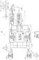
- FIG. 1 shows a typical "concurrent dual-band" system 10 using baseband DPD implemented by a pre-distortion system 12.
- the pre-distortion system 12 receives complex-valued baseband information-bearing signals u L (n) and u U (n) for the lower and upper bands from a lower and upper band source 14a and 14b, respectively.
- the signals u L (n) and u U (n) are pre-distorted by a pair of digital pre-distorters 16a, and 16b, referred to collectively herein as digital pre-distorters 16, to produce the complex-valued baseband distorted signals y L (n) and y U (n).
- the signals from both bands, y L (n) and y U (n), are up-converted by an upconverter 18 to analog signal z ⁇ i (t) at frequency ⁇ c and input to a power amplifier (PA) 20 to produce the real-valued output signal z ⁇ o (t) to be transmitted over the air.
- PA power amplifier
- the system is considered "concurrent dual-band" since the PA transmits both bands simultaneously and treats them as a single contiguous region of frequency of width W - even if the spacing between bands spans several hundreds of MHz.
- a transmit observation receiver 22 that includes a down converter and digitizer 24, down-converts and digitizes the analog PA output signal z ⁇ o (t) as observed via a coupler.
- a "Tap Weight Evaluation" block 26 produces a set of tap weights, also referred to simply as taps, required for each band based on the baseband samples r L (n) and r U (n) observed on both bands by the observation receiver 22.
- Tap weight adaptation requires access to either the DPD actuator input signals u L (n) and u U (n) or its output signals y L (n) and y U (n), depending on whether the DPD system employs a "direct learning” or "indirect learning” architecture. Most often, only one of the learning architectures is selected for any given system based on the nature of its PA nonlinearity or its chosen adaptation scheme.
- Equations 1 show a signal implementation of a typical baseband DPD architecture for a concurrent dual-band system.
- the lower band actuator synthesizes its desired pre-distorted output y L (n) by summing together over a memory depth of M samples the outputs from B basis functions ⁇ L,b ( ⁇ ) scaled by the lower band signal u L (n-m) and weighted by the complex-valued tap weights ⁇ w L (n-m,b) ⁇ .
- the upper band actuator produces y U (n) similarly using B basis functions ⁇ U,b ( ⁇ ) and tap weights ⁇ w U (n-m,b) ⁇ .
- the basis functions ⁇ L,b ( ⁇ ) and ⁇ U,b ( ⁇ ) must be smooth continuous functions of the signal envelopes
- Equations 1 takes the form shown in Equations 2, where Q+1 represents the maximum order of the nonlinearity in question.
- FIG. 2 An illustrative example of spline-based DPD for the single-band case is shown in FIG. 2 .
- the basic idea is to approximate the basis function ⁇ (
- third order (or cubic) splines are used since they are easy to compute and have continuous first and second order derivatives yielding well-behaved approximations. As shown in FIG.
- is divided into B intervals or "bins", and the borders between the bins are denoted as "knots” q 0 ,q 1 ,...,q K .
- ) is approximated by a cubic spline that is forced by construction to be continuous at the knots.
- the knot positions may be distributed uniformly to reduce computational complexity.
- ) may be approximated by fitting a cubic spline to the four knots surrounding that bin using the corresponding ordinates ⁇ Q(p-1),Qp Q(p+1), Q(p+2) ⁇ , which must be estimated for a particular PA.
- Equations 3 Based on the formulation of a Hammerstein pre-distorter model, the above cubic spline approximation is incorporated for the required non-linearity into the DPD actuator model given by Equations 3, where w(m) denotes a set of complex-valued tap weights, M is the basis of the Catmull-Rom spline, and the abscissa ⁇ q(p-1),q(p), q(p+1), q(p+2) ⁇ for the knot points are assumed to be uniformly distributed.
- Equation 4 provides the DPD actuator operation for a single-band actuator based on a second version of cubic splines, where ⁇ (j,m) ⁇ and ⁇ (p,m) ⁇ represent the complex-valued tap weights for the actuator. Note that separate cubic spline fitting is done for each memory term supported by the actuator.
- spline-based DPD schemes are implemented using lookup tables (LUTs) to reduce complexity, rather than computing explicitly the cubic terms in Equation 3 or Equation 4 based on the four knots for a particular bin.
- the dynamic range for the abscissa of the p-th bin shown in FIG. 2 may be quantized to a finite fixed-point resolution and the cubic spline computations may be pre-computed a-priori for each possible quantized signal envelope value and stored in a LUT.
- the LUT provides a cheap hardware mechanism to implement the DPD actuator, but complicates the fast adaptation of the tap weights since every time the tap weights need to be updated, the entire contents of the LUTs must be re-computed.
- the single-band DPD schemes based on cubic splines may be extended to support concurrent dual-band operation by synthesizing 1D splines independently for each band and then extending them to 2D via a tensor product of the 1D cubic spline interpolations in each band.
- One example of this approach is to produce a 2D-DPD scheme based on cubic splines and implemented using lookup tables (LUTs). Equation 5 shows the resultant tensor product of the 1D cubic splines, where x L and x U represent the baseband input signals of each band, u denotes the 1D knot index for the signal amplitude of the lower band, and v denotes the 1D knot index for the signal amplitude of the upper band.
- Equation 5 The expression in Equation 5 would be evaluated at each memory term supported by the actuator.
- Equation 5 extending the cubic spline pre-distorter equations from single-band to dual band results in a significant increase in computational complexity due to the squaring of the terms involved in the distortion products; a 1D cubic spline with 3rd order terms results in 6th order terms to be computed when a 2D cubic spline is formed as a tensor product of 1D cubic splines.
- Dual-band DPD such as 2D-DPD based on GMPs admit the use of a wide variety of tap weight adaptation and tracking schemes because their outputs are expressed as a linear function of their tap weights.
- tap weight adaptation and tracking schemes because their outputs are expressed as a linear function of their tap weights.
- Cubic splines can address issues with high order non-linearity and the fixed-point dynamic range issues found in GMP-based schemes but they also suffer from serious drawbacks when used to implement concurrent dual-band pre-distortion:
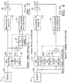
- the indirect learning architecture acts fundamentally to "post-distort" the PA output z ⁇ o (t) by passing its baseband equivalent r(n) through a "reverse” DPD actuator model 28.
- the tap weights of the reverse DPD actuator model 28 are updated or tuned by tap weight updater 30 to drive to zero the error signal e(n) between an y(n) of a DPD actuator 32 and the output of the reverse DPD actuator model 28.
- the tap weights of the reverse DPD actuator model 28 may then be transferred for use in the forward DPD actuator 32.
- the direct learning architecture acts fundamentally to "pre-distort" the PA in the "forward" direction by using the baseband actuator input u(n) as the ideal reference signal for tap adaptation, and tuning to zero the error signal e(n) formed between this ideal reference and the observed r(n) from the PA output.
- r(n) the baseband equivalent of z ⁇ o (t) is received by a DPD actuator model 29 which receives u(n) and presents an output to the tap weight updater 31.
- the tap weight updater 31 receives an error signal e(n) which is the difference between r(n) and u(n).
- the weights are applied to the DPD actuator 33 which produces the pre-distorted signal y(n).
- DPD actuator model 29 is shown explicitly in FIG. 4 for clarity, in principle its function can be absorbed into the actual DPD actuator 33. More sophisticated "direct learning" architectures incorporate explicit PA model identification with inner & outer control loops as required for general "self-tuning inverse control" systems.
- some examples provide, for each of at least one band of the input signal, determining a signal envelope, a signal envelope being determined for each of a plurality of successive bins, each bin having a knot at each edge of the corresponding bin.
- the method includes computing a spline function assigned to each knot, the spline function having a left spline and a right spline. Each of the left spline and the right spline have a value of unity at the knot and a value of zero at left and right neighboring knots, respectively.
- each bin is associated with two overlapping successive spline functions that overlap each other in only one bin.
- Each spline function is computed as a function of one of the signal envelope and a delayed signal envelope in the band.
- the method includes, for each bin, delaying one of the signal envelope and a spline function in each of at least one tap delay line to model a pre-selected memory depth.
- the method includes determining a tap weight for each knot; multiplying each spline function at each knot by its respective tap weight; and generating a pre-distorted signal using a sum of tap-weighted products of the spline functions and a delayed input signal.
- the method when there are a plurality of bands, the method includes forming cross products of the spline functions of the different bands; and multiplying the cross products at each knot by a respective tap weight; and wherein generating the pre-distorted signal includes adding a sum of tap-weighted cross products to the sum of tap-weighted products.
- the method when there are a plurality of bands, the method includes forming inter-band polar spline functions having a magnitude and phase based on the signal envelopes of the plurality of bands; and multiplying the inter-band polar spline functions at each of a plurality of radial knots by a respective tap weight at each knot; and wherein generating the pre-distorted signal includes adding a sum of tap-weighted polar spline functions to the sum of tap-weighted products.
- the method for each band, includes scaling the signal envelope and computing the spline function as a function of one of the scaled signal envelope and a delayed scaled signal envelope.
- the method includes inputting the signal envelope to a pre-emphasis unit that maps each value of the signal envelope to a scaled value of the signal envelope. In some examples, the mapping is based on cumulative distribution function of the signal envelope. In some examples, the method includes selecting, by multiplexers, different ones of the delayed input signals and spline functions to be included in the pre-distorted signal. In some examples, the generating includes, for each band: storing each tap weight in a memory; multiplying the tap weights by spline functions in parallel branches to produce a first set of multiplications; combining the first set of multiplications; and multiplying the combined multiplications by a delayed input signal.
- "a" is a stretching parameter equal to a bin width, so that the spline function spans a width of two bins.
- "a" is a stretching parameter equal to a bin width, so that the spline function spans a width of two bins.
- the left spline is associated with a first stretching parameter and the right spline is associated with a second stretching parameter different from the first stretching parameter to accommodate adjacent bins of unequal width.
- calculating the sum of tap-weighted products includes, for each bin: multiplying a tap weight determined for a left knot of the bin by a right spline of the left knot to form a first product; multiplying a tap weight determined for a right knot of the bin by a left spline of the right knot to form a second product; summing the first product and the second product to form a first sum; and multiplying the first sum by a value of the delayed input signal.
- some examples provide a digital pre-distorter, DPD, configured to pre-distort an input signal to compensate for a non-linear operation of a power amplifier.
- the DPD includes an envelope detector configured to determine a signal envelope for each of at least one band of the input signal, a signal envelope being determined for each of a plurality of successive bins, each bin having a knot at each edge of the corresponding bin.
- the DPD includes a spline function calculator configured to compute and assign, for each band, a spline function to each knot.
- the spline function has a left spline and a right spline, each of the left spline and the right spline having a value of unity at the knot and a value of zero at left and right neighboring knots, respectively. Consequently, each bin is associated with two overlapping successive spline functions that overlap each other in only one bin. Also, each spline function is computed as a function of one of the signal envelope and a delayed signal envelope in the band.
- the DPD also includes tapped delay lines configured to delay, for each bin, one of the signal envelope and a spline function to model a pre-selected memory depth.
- the DPD also includes a combiner configured to multiply tap weights by the spline functions and delayed input signals to form tap weighted products and to combine the tap weighted products to generate a pre-distorted signal.
- a set of multipliers form cross products of the spline functions of different bands and multiply each cross product at each knot by a respective tap weight.
- the combiner generates the pre-distorted signal by adding a sum of tap-weighted cross products to the combination of tap-weighted products.
- the spline function calculator forms inter-band polar spline functions having a magnitude and phase based on the signal envelopes of the plurality of bands.
- the combiner is configured to multiply the inter-band polar spline functions at each of a plurality of radial knots by a respective tap weight at each knot; and where generating the pre-distorted signal includes adding a sum of tap-weighted polar spline functions to the sum of tap-weighted products.
- the DPD includes a pre-emphasis unit configured to scale the signal envelope prior to computing the spline function as a function of one the scaled signal envelope and a delayed scaled signal envelope.
- the DPD further includes a pre-emphasis unit configured to map each value of the signal envelope to a scaled value of the signal envelope.
- the mapping is based on the cumulative distribution function of the signal envelope.
- the combiner includes, for each band: a memory configured to store each tap weight; a plurality of first multipliers configured to multiply the tap weights by spline functions in parallel branches; a combiner configured to combine the multiplications; and a second multiplier configured to multiply the combined multiplications by a delayed input signal.
- "a" is a stretching parameter equal to a bin width, so that the spline function spans a width of two bins.
- "a" is a stretching parameter equal to a bin width, so that the spline function spans a width of two bins.
- the left spline is associated with a first stretching parameter and the right spline is associated with a second stretching parameter different from the first stretching parameter to accommodate adjacent bins of unequal width.
- the combiner includes, for each bin: a first multiplier configured multiply a tap weight determined for a left knot of the bin by a right spline of the left knot to form a first product; a second multiplier to multiply a tap weight determined for a right knot of the bin by a left spline of the right knot to form a second product; an adder to sum the first product and the second product to form a first sum; and a third multiplier to multiply the first sum by a value of the delayed input signal.
- some embodiments include a method of updating tap weights in a digital pre-distorter, DPD, the DPD configured to compensate for a non-linear operation of a power amplifier.
- the method includes computing an average power of each input to a plurality of tap weight calculators over a plurality of samples.
- the method also includes computing an approximate logarithm of the average power of each input; and modulating a step size of an adaptation process to update each tap weight.
- the step size is modulated based on the approximate logarithm of the average power of the input.
- the method includes computing the approximate logarithm which includes performing a binary shift of a correlation statistic associated with each tap weight.
- the method further includes accumulating a computed power average during a first period of time in a first memory while reading a previously computed power average from a second memory, and accumulating a computed power average during a second period of time in the second memory while reading a previously computed power average from the first memory.
- the method further includes further modulating the step size based on a sum of products of a vector of tap weight inputs and a conjugate of an error value, the summation being over a plurality of samples.
- the products are computed with a first precision and then reduced to a second precision before being used to update the tap weights.
- the method further includes selectively operating in one of a direct mode to compute a difference between an input signal and an observation signal and an indirect mode to compute a difference between an output of the DPD and an output of a DPD actuator model, the DPD actuator model computing an estimate of a pre-distorted signal.
- the tap weights are based on spline functions, a spline function being a function of an envelope of an input signal to be pre-distorted, a spline function being assigned to each knot of a plurality of successive bins.
- a spline function has a left spline and a right spline, each of the left spline and the right spline having a value of unity at the knot and a value of zero at left and right neighboring knots, respectively, so that each bin is associated with two overlapping successive spline functions that overlap each other in only one bin.
- some embodiments provide a tap weight evaluator to update tap weights for use in conjunction with a digital pre-distorter, DPD, the DPD configured to compensate for a non-linear operation of a power amplifier.
- the tap weight evaluator includes an average power calculator configured to compute an average power of each input to a plurality of tap weight computations over a plurality of samples.
- the tap weight evaluator also includes a logarithm calculator configured to compute an approximate logarithm of the average power of each input.
- the tap weight evaluator further includes a least mean squares, LMS, tap correlator updater configured to modulate a step size of an adaptation process to update each tap weight. The step size is modulated based on the approximate logarithm of the average power of the input to the tap weight computation.
- the logarithm calculator is configured to perform a binary shift of a correlation statistic associated with each tap weight.
- the tap weight evaluator further includes memory circuitry configured to accumulate a computed power average during a first period of time in a first memory while a previously computed power average is read from a second memory, and configured to accumulate a computed power average during a second period of time in the second memory while a previously computed power average is read from the first memory.
- the LMS tap correlator updater is further configured to further modulate the step size based on a sum of products of a vector of tap weight inputs and a conjugate of an error value, the summation being over a plurality of samples.
- the products are computed with a first precision, and then reduced to a second precision before being used to update the tap weights.
- the tap weight evaluator further includes an error signal calculator configured in a direct mode to compute a difference between an input signal and an observation signal and configured in an indirect mode to compute a difference between an output of the DPD and an output of a DPD actuator model, the DPD actuator model computing an estimate of a pre-distorted signal.
- the tap weights are based on spline functions, a spline function being a function of an envelope of an input signal to be pre-distorted, a spline function being assigned to each knot of a plurality of successive bins.
- a spline function has a left spline and a right spline, each of the left spline and the right spline having a value of unity at the knot and a value of zero at left and right neighboring knots, respectively, so that each bin is associated with two overlapping successive spline functions that overlap each other in only one bin.
- the embodiments reside primarily in combinations of apparatus components and processing steps related to digital pre-distortion for pre-distorting a single or multi-band signal to be amplified by a non-linear power amplifier. Accordingly, the system and method components have been represented where appropriate by conventional symbols in the drawings, showing only those specific details that are pertinent to understanding the embodiments of the present disclosure so as not to obscure the disclosure with details that will be readily apparent to those of ordinary skill in the art having the benefit of the description herein.
- relational terms such as “first” and “second,” “top” and “bottom,” and the like, may be used solely to distinguish one entity or element from another entity or element without necessarily requiring or implying any physical or logical relationship or order between such entities or elements.
- Embodiments described herein encompass a novel 2D-DPD architecture based on splines for digital pre-distortion of concurrent multi-band transmitters that provides effective linearization with low computational complexity, a high degree of flexibility for addressing a wide variety of PA's with a single architecture, and admits a low-cost closed-loop real-time adaptation of its tap coefficients. Further, embodiments described herein encompass a closed-loop algorithm to perform the initial acquisition of the tap weights for the spline-based concurrent dual-band DPD actuator, and to provide real-time adaptive tracking of the actuator weights for continuous operation in non-stationary conditions.
- Some embodiments provide arrangements to implement practical low cost DPD for single band, concurrent dual-band and other multi-band systems while avoiding the drawbacks of GMP-based approaches such as the fixed-point difficulties and high cost of synthesizing high-order nonlinearities, and address the explosion in LUT depth and prohibitive LUT re-computation cost of schemes based on cubic splines.
- basis functions are described that overcome problems of known basis functions, such as GMP basis functions and cubic splines as described above. Then, methods of implementing direct adaptation of tap weights via low-cost, closed-loop filter schemes will be described.
- Basis functions ⁇ b ⁇ constructed from overlapping splines provides a simple yet effective means to subdivide the dynamic range of the signal envelope
- the bin widths may be chosen to be identical or they may be spaced non-uniformly to account for a non-uniform distribution of signal envelope.
- an overlapping low-complexity spline function is assigned to each knot, and constructed in such a way that its value is unity at the knot position, and falls to zero at both of its two neighboring knots, and each pair of neighboring knot functions exhibit a continuous 1st order derivative at the knot boundaries where they meet.
- Each spline function is a second order spline ⁇ b ,2 ( a , u ) given by Equation 6.
- the b -th spline is centered at the b -th knot where its value is unity, and it decays to zero at knot b - 1 and knot b + 1.
- the parameter ⁇ stretches the (normalized) spline so that it spans the width of two bins.
- ⁇ b , 2 a u ⁇ 1 2 u a / 2 2 , 0 ⁇ u ⁇ a / 2 1 ⁇ 1 2 u ⁇ a a / 2 2 , a / 2 ⁇ u ⁇ 3 a / 2 1 2 2 ⁇ a ⁇ u a / 2 2 , 3 ⁇ a / 2 ⁇ u ⁇ 2 ⁇ a
- each spline is identical with the same a parameter. Knots with non-uniform spacing may be supported by the following extension to the above construction.
- the actuator maintains a complex-valued weight w b ( m ) for each knot.
- These tap weights can be tuned actively by the Tap Weight Evaluation block 26 of FIG. 1 based on an appropriate closed-loop algorithm. By tuning the tap weights to the appropriate value, the DPD predistorter can linearize the PA.
- Distortion products are produced using the above construction of overlapping splines using the set of stored tap weights ⁇ w b ( m ) ⁇ as follows.
- the "active bin” is identified as the bin into which the current signal envelope value
- the active bin identifies the particular "right basis function" of the left-side knot and "left basis function" of the right-side knot that forms the boundary of the active bin.
- the distortion product w b ( m ) ⁇ ⁇ b ,2 ( a R , a R - z ) + w b +1 ( m ) ⁇ ⁇ b +1 ( a L , z ) forms the "interpolated" contribution to the current signal envelope, as expressed by the offset z from the left-size knot).
- FIG. 1 For illustration, FIG. 1
- Equation 7 provides a normalized 3rd order spline that offers continuous 2nd order derivatives in exchange for an increase in its computational complexity.
- these splines are not used strictly for interpolation there is very little difference observed between the 2nd and 3rd order splines provided a sufficient number of knots is used. For this reason, the 2nd order spline is preferred as it has the least computational complexity.
- a u ⁇ 2 a ⁇ x a 2 ⁇ a ⁇ x a ⁇ 3 2 + 1 , 0 ⁇ u ⁇ a 2 x ⁇ a a 2 ⁇ x ⁇ a a ⁇ 3 2 + 1 , a ⁇ u ⁇ 2 ⁇ a
- a number of hardware optimizations may be performed to reduce the computational complexity required to evaluate the left and right spline functions based on Equation 6.
- One possible architecture involves pre-computation and storage in a lookup table of the distortion term w b ( m ) ⁇ ⁇ b ,2 ( a R , a R - z ) + w b +1 ( m ) ⁇ ⁇ b +1 ( a L , z ) as a function of the quantized signal envelope offset z .
- This provides an economical actuator since the operation then consists of a single table lookup.
- the LUT size may become prohibitive since a large resolution (typically 12 bits or higher) is required for z .
- the LUT depth may become prohibitive in the dual-band case, where the index grows to 24 or more bits.
- tap weight adaptation may be costly since separate circuitry must be allocated to update the tap weights ⁇ w b ( m ) ⁇ directly, and then additional circuitry must be used to re-compute the LUT contents for each z value every time the tap weights change.
- Equation 6 The spline functions of Equation 6 are selected to be low-cost to enable direct computation in hardware. This helps keep the LUT size much smaller since then only the tap weights ⁇ w b ( m ) ⁇ must be stored, and their depth varies only by the number of knots B , which will be a few tens in number for most cases in practice. Further cost savings can be obtained in evaluating ⁇ b ,2 ( ⁇ ) and ⁇ b +1,2 ( ⁇ ) in certain cases:
- FIG. 6 is a block diagram of an exemplary circuit for computing second order splines of Equation 6.
- the circuit of FIG. 6 includes memory bank 36 which stores the values of the knots 0 through N-1.
- the knot values from the memory 36 are input to a bank 38 of comparators 40 and 42.
- Another input to the comparators 40 and 42 is the signal envelope
- the function of the comparators 40 and 42 are to choose the lesser of the knot value and the signal envelope value in order to determine the left knot of the current bin and the offset from the left knot at which the signal envelope is evaluated.
- the output of the comparators 40 and 42 are input to each of a bank 44 of AND gates 46 which output the logical AND of the outputs of comparators 40 and 42.
- the output of the AND gates is input to a "one hot" selector 48 which outputs a signal to a multiplexer 50. Although only one line is shown connecting the AND gates to the selector 48, actually there is a separate line from each AND gate output to the selector 48, so that the line connecting the AND gate outputs to the selector 48 is a bus.
- the output of the multiplexer 50 is a value of the left knot of the bin containing the input signal envelope. This value is subtracted from the signal envelope at a subtractor 52 to produce an offset from the left knot into the current bin.
- the output of the subtractor 52 is input to a multiplier/adder unit 54, which contain the multipliers and subtractors to compute the terms of Equation 6.
- the output of the subtractor 52 is also input to a comparator 56 which to determine which interval of the basis function of FIG. 6 is being defined.
- the outputs of the multiplier/adder unit 54 are input to a multiplexer 58 which is controlled by the output of the comparator 56 to output the right spline function value.
- the left spline is computed at the subtractor 60.
- a single-band DPD actuator may be formulated using the overlapping splines as shown in Equation 8 and outlined as follows:
- Gain-based signal envelop pre-emphasis involves multiplying the signal by a fixed constant ⁇ to scale the signal envelope before computing its basis functions.
- the envelope of the input signal is determined at block 62.
- This envelope is multiplied at multiplier 64 by ⁇ and input to a left spline basis function calculator 66.
- the right spline is computed at the subtractor 60. Consequently, distortion terms are evaluated using ⁇ b * ( ⁇ ⁇
- This gain boost serves to excite a wider portion of the available signal envelope dynamic range, leading to a wider subset of the tap weights ⁇ w b ( m ) ⁇ being excited by the DPD subsystem. As a consequence, the DPD modeling capability is improved significantly. Note that this boost gain ⁇ does not impact the data path in any way; it simply changes the active bin index b *that is excited by a particular value of the signal envelope.
- the method for each band, includes scaling the signal envelope and computing the spline function as a function of one of the scaled signal envelope and a delayed scaled signal envelope.
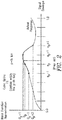
- FIG. 8 Further sophistication in the modeling capability may be achieved by replacing the gain-based pre-emphasis with a LUT 65, as shown in FIG. 8 that introduces a programmable mapping between the observed signal envelope and that used to excite the overlapping quadratic splines.
- the top plot, a) shows the estimated probability density function (PDF) of a wideband LTE signal.
- CDF estimated cumulative distribution function
- the bottom plot, c) shows the effect of the LUT on the overlapping basis functions - the impact of the LUT is to implement overlapping basis functions with non-uniform knot spacing in order to achieve the equal probability use of each tap weight in the model. This may be compared with the uniform knot spacing of FIG. 5 .
- the method includes inputting the signal envelope to a pre-emphasis unit that maps each value of the signal envelope to a scaled value of the signal envelope.
- the mapping is based on cumulative distribution function of the signal envelope.
- the overlapping quadratic splines described above may be extended to support pre-distortion of concurrent multi-band signals.
- Two distinct forms are considered: a rectangular form and a polar form.
- the dual-band basis functions are extended in a straightforward manner from the single-band case.
- two sets of overlapping quadratic splines are defined; one for each band.
- Each set of splines is defined as outlined for the single-band case described above.
- a set of B L knots is defined for the lower band, and a second set of B U knots is defined for the upper band.
- the process of this disclosure does not require B L ⁇ B U although this will be assumed hereafter for simplicity of discussion.
- As in the signal-band case only two neighboring overlapping splines will be excited for any given signal envelope observed in each band.
- bins b * and b * + 1 represent the two knots excited for the lower band, and let d * and d * + 1 represent the two knots excited for the upper band.
- Intra-band distortion may be synthesized for the lower band from distortion products w L,b * ( m , v ) ⁇ ⁇ L , b * (
- w U , d * ( m , v ) ⁇ ⁇ U , d * (
- ⁇ w L , b ( m , v ) ⁇ represent the complex-valued tap weights for the lower band
- ⁇ w U , d ( m , v ) ⁇ represent the complex-valued tap weights for the upper band.
- Inter-band or “cross-term” distortion must also be included for successful pre-distortion of concurrent dual-band transmitters.
- Cross-terms may be synthesized directly for each band by acknowledging that a total of four cross-terms may be formed from the same two pairs of non-zero overlapping splines used to model the "intra-band” distortion in each band. These four products are shown together in Equation 9.
- Distinct distortion products for each band may be generated based on the four basis function products in Equation 9 by assigning a distinct "cross-term" weight for each band, and by scaling the distortion product by the desired signal term ( u L ( n - m - v ) or u U ( n - m - v )) for that band.
- the resulting dual-band DPD actuator that includes both the "intra-band” and "inter-band” distortion products is described by Equation 10 for the lower band and by Equation 11for the upper band. Extensions for more than two bands follows in a straightforward and analogous manner.
- B L ⁇ B U the total number of "cross" tap weights is B L ⁇ B U in each band.
- ⁇ R ( n ) ⁇ exp( j ⁇ ⁇ ( n )) may be expressed as a polar magnitude R ( n ) and phase rotation ⁇ ( n ).
- a single set of overlapping splines may be defined for R ( n ) using the construction proposed above with respect to Equation 6, to produce the cross-term distortion based on a single set of cross-term weights ⁇ x L,r *, ⁇ * ( m , v ) ⁇ and ⁇ x U , r *, ⁇ * ( m , v ) ⁇ for each band and indexed by the active radial splines r * and r * + 1 and the active quantized rotation ⁇ *.
- the method when there are a plurality of bands, includes forming inter-band polar spline functions having a magnitude and phase based on the signal envelopes of the plurality of bands; and multiplying the inter-band polar spline functions at each of a plurality of radial knots by a respective tap weight at each knot; and wherein generating the pre-distorted signal includes adding a sum of tap-weighted polar spline functions to the sum of tap-weighted products.
- Equations 12 and 13 provide the DPD actuator based on a polar formulation for the lower and upper bands, respectively. Note that both bands use the same expressions for the "thru" distortion terms in both rectangular and polar forms.
- the polar form provides a reduction in computational complexity as compared to the rectangular form. Extension of the polar formulation to > 2 bands follows in a straightforward and analogous manner i.e., spherical coordinates for 3 bands, etc.
- Some examples provide a robust and flexible framework for single-band, dual-band and multi-band distortion synthesis where the basis function selection, bin and knot assignment, and signal envelope scaling and/or pre-emphasis may all be selected as appropriate to maximize modeling capability and performance or to tune computational complexity to meet desired implementation requirements. Only the rectangular form is presented hereafter for the sake of brevity.
- FIG. 11 is a block diagram of an exemplary DPD actuator 68. Complex-valued signals are denoted using solid lines, whereas real-valued signals are denoted using dotted lines.
- the actuator includes the following components:
- the method when there are a plurality of bands, includes forming cross products of the spline functions of the different bands; and multiplying the cross products at each knot by a respective tap weight; and wherein generating the pre-distorted signal includes adding a sum of tap-weighted cross products to the sum of tap-weighted products.
- the method includes selecting, by multiplexers, different ones of the delayed input signals and spline functions to be included in the pre-distorted signal.
- the rectangular dual-band tap combiner 82a for the lower band is shown in FIG. 12 , and which performs the computation of Equation 10 for a single time delay/skew assignment ( m, v ) as determined by the multiplexer settings.
- a purpose of the circuitry of FIG. 12 is to determine the tap weight inputs to tap weights adaptation circuitry that is described below.
- the circuitry of FIG. 12 has the following features:
- calculating the sum of tap-weighted products includes, for each bin: multiplying a tap weight determined for a left knot of the bin by a right spline of the left knot to form a first product; multiplying a tap weight determined for a right knot of the bin by a left spline of the right knot to form a second product; summing the first product and the second product to form a first sum; and multiplying the first sum by a value of the delayed input signal.
- the data signals that multiply each tap weight in Equations 10 and 11 may be collected into the rows of a data matrix (one row for each sample n).
- Data samples d LT ( n ) multiply weights w LT
- samples d LX ( n ) multiply weights w LX
- data samples d L n d LT T n , d LX T n T multiply weights w L for the lower band, and similarly for the upper band.
- Equation 16 The solution is given by Equation 16.
- w L D L ⁇ ⁇ D L ⁇ 1 ⁇ D L ⁇ ⁇ z
- w U D U ⁇ ⁇ D U ⁇ 1 ⁇ D U ⁇ ⁇ z U
- the solution to Equation 16 requires inversion of the matrices A L ⁇ ( D L ⁇ ⁇ D L ) -1 and A U ⁇ ( D U ⁇ ⁇ D U ) -1 .
- the Cholesky decomposition A L ⁇ L L ⁇ L L ⁇ with back-substitution often provides a feasible yet costly solution in practice.
- Equation 17 The "stochastic gradient” (SG) or “least mean squares” (LMS) algorithm adaptively solves for the tap weights in Equation 17, thus providing an alternative to the least squares approach that is computationally less complex than the least squares approach.
- the update equations are given in Equation 17 where ⁇ L and ⁇ U are the step-size parameters for the lower and upper bands, respectively.
- the standard LMS algorithm can suffer from gradient noise amplification since its update term, for example d L n ⁇ e L * n in Equation 17, is directly proportional to the data input vector. For applications where the data can exhibit large statistical fluctuations, this drawback can be avoided with the normalized LMS algorithm of Equation 18, where the update term is normalized with respect to the squared norm of the data input vector.
- the least squares tap weight solution has three primary drawbacks that limit its application in practice:
- the standard LMS algorithm exhibits slow convergence behavior when then eigenvalue spread of the matrices A L and A U is large.
- the stepsize parameter must be set carefully in relation to the strength of the correlation matrix eigenvalues or else instability may result. These issues are particularly problematic for non-linear systems.
- the DPD actuators of this disclosure demonstrate this typical behavior with the standard LMS algorithm of Equation 17. Instability is observed unless the step-size parameters ⁇ L and ⁇ U are set very small, and otherwise convergence of the taps does not occur and appears to be swamped by the tap noise inherent in the large number of small-valued tap weights related to the cross-terms.
- the normalized LMS algorithm of Equation 18 does a poor job of solving the gradient noise amplification problem for the DPD actuator since the instantaneous magnitude (
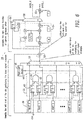
- FIGS. 13 and 14 show simulation results of the average tap input power as a function of tap index for the "thru” ( FIG. 13 ) and “cross” ( FIG. 14 ) taps in the left and right side plots, respectively, over the suite of P sets of tap weights. These results show that the average tap input power varies widely over three orders of magnitude as a function of the tap index.
- the dashed lines in FIGS. 13 and 14 show the tap input power averaged over all of the "thru” or “cross” taps, indicating even the average power E ⁇
- the normalized LMS algorithm cannot be used successfully to adapt the tap weights of the DPD actuators of Equations 10 and 11 due to the wide variability of the tap input magnitudes across its suite of tap weights; the normalized LMS algorithm suffers from instability and very poor convergence behavior due to these characteristics.
- Some embodiments provide a novel closed-loop algorithm to perform the initial acquisition of the tap weights for the concurrent dual-band DPD actuator based on overlapping splines, and to provide real-time adaptive tracking of tap weights for continuous operation in non-stationary conditions.
- the algorithm is low-cost and suitable for efficient implementation in fixed-point hardware, and does not suffer from the drawbacks of high-cost, poor numerical stability and limited adaptation rates inherent with the LMS algorithms in the prior art.
- some embodiments provide a novel tap-specific power normalization scheme to modulate the step size used for each tap according to its observed average input power.
- Some embodiments use a logarithmic step-size normalization for low-cost hardware implementation.
- a block-based LMS update strategy and power statistic gathering circuitry address directly the unique probabilistic nature of the dual-band concurrent signal to yield robust operation in non-stationary environments.
- FIG. 15 shows a block diagram of exemplary adaptation hardware 105 for computing tap weights. The following points summarize the high level operation of the circuitry of FIG. 15 :
- Equation 19 describes the closed-loop adaptation scheme described herein for updating the tap weights of the DPD actuator 68 with overlapped splines of Equation 6.
- FIG. 16 illustrates the tap update and transfer schedule for some embodiments.
- the schedule of FIG. 16 is configured to satisfy the following requirements:
- FIG. 17 shows the front-end spline processing 106 for some embodiments.
- This circuitry replicates many of the same functions performed by the DPD actuator 68 which may be partitioned in a different device, where like elements are like-numbered and perform like functions.
- the circuitry produces various components of the tap weight input signals d L ( n ) and d U ( n ) required for tap weight adaptation, along with the associated control parameters such as the over-lapping spline basis function values and their corresponding indices.
- FIG. 18 shows circuitry for the Error Branch Processing 108 to support "indirect learning.” This embodiment implements P identical branches of the circuitry in total.
- the circuitry in FIG. 18 replicates exactly the function of a "Dual-Band Tap Combiner" of FIG. 12 , where like elements are like numbered and perform like functions.
- FIG. 19 shows a block diagram of the circuitry required for Signal Statistics Branch Processing 112. There are P identical branches of the circuitry in total.
- the signal statistics branch processing hardware performs the following functions:
- FIG. 20 shows the POWER STAT PROCESSING circuitry 124 of FIG. 19 in detail.
- the power stat processing circuitry 124 generates the products of input signals and basis functions in multipliers 136a, 136b and 136c, as needed, to re-compute the signals input to each of the six active tap weights in each band. These twelve tap weight inputs 138 are fed to downstream hardware for "data/error" correlation processing.
- Magnitude units 140a and 140b calculate the instantaneous power of the tap weight inputs 138 and add them together by adders 142a and 142b to obtain a single "instantaneous power" statistic for the current sample instant.
- Downstream hardware accumulates this statistic in each of the memory bank addresses corresponding to the current twelve active tap weights.
- FIG. 21 shows the details of the POWER STAT ACCUM blocks 126 of FIG. 19 used to accumulate the average power statistics of each tap weight input.
- the circuit operates as follows:
- a method of updating tap weights further includes accumulating a computed power average during a first period of time in a first memory while reading a previously computed power average from a second memory, and accumulating a computed power average during a second period of time in the second memory while reading a previously computed power average from the first memory.
- FIG. 22 shows the circuitry for "data/error" correlation for some embodiments as computed by error/data correlation processor 128 of FIG. 19 . Only functionality for a single band is shown. There are as many instances of this circuitry as there are bands in the input signal. Note that the error signal is conjugated by a conjugator 164, as indicated in Equation 19. The conjugate of the error signal is multiplied at multipliers 166 by the input tap weights received from the output 138 of the power stat processing circuitry 124. The products of the multipliers 166 are shifted right by shift units 168. Precision reducers 170 reduce the precision of the outputs of the shift units 168 to produce the tap weight updates 172.
- tap weight updates 172 are accumulated by a circuit similar in form to the circuit of FIG. 21 , except that TOTPOW_I is replaced by an update signal of the tap weight updates 172. Thus, there are a total of 6 additional circuits, one for each tap weight update.
- a method for updating tap weights includes modulating the step size based on a sum of products of a vector of tap weight inputs and a conjugate of an error value, the summation being over a plurality of samples.
- the products are computed with a first precision and then reduced to a second precision before being used to update the tap weights.
- FIG. 23 shows a block diagram of the LMS tap correlator update processing some embodiments and corresponds to element 114 of FIG. 15 .
- the circuit operates as follows:
- FIG. 24 is a flowchart of an exemplary process for generating a pre-distorted signal based on overlapping splines.
- a signal envelope is determined by an absolute value determiner 70 in each of a plurality of successive bins (block S100).
- a spline function is computed and assigned to each knot of each bin by a spline function calculator 74.
- the spline function has a right and left spline, each having a value of unity at a knot and a value of zero at a neighboring knot, such that each bin is associated with overlapping successive spline functions that overlap in only one bin.
- Each spline function is computed by a spline function calculator 34 as a function of one of the signal envelope and a delayed signal envelope of the band (block S 102). For each bin, one of the signal envelope and a spline function is delayed in each of at least one tap delay line 78 to model a pre-selected memory depth (block S104). A tap weight is determined for each knot (block S106). Each spline function at each knot is multiplied by its respective tap weight at one of multipliers 96 (block S108). A pre-distorted signal is generated using a sum of tap-weighted products of the spine functions and a delayed input signal (block S110).
- FIG. 25 is a flowchart of an exemplary process for modulating a step size for an adaptation process for updating tap weights.
- An average power of each input to a plurality of tap weight calculators is computed power determiners 140 (block S112).
- An approximate logarithm of the average power of each input is computed (block S114).
- a step size of the adaptation process to update each weight is modulated based on the approximate logarithm of the average power of the input (block S116).
- Embodiments include a closed-loop algorithm for acquiring and adapting the complex-valued tap weights of a concurrent multi-band DPD actuator based on overlapping splines.
Landscapes
- Physics & Mathematics (AREA)
- Nonlinear Science (AREA)
- Engineering & Computer Science (AREA)
- Power Engineering (AREA)
- Algebra (AREA)
- General Physics & Mathematics (AREA)
- Mathematical Analysis (AREA)
- Mathematical Optimization (AREA)
- Pure & Applied Mathematics (AREA)
- Amplifiers (AREA)
Claims (14)
- Verfahren zur Aktualisierung von Abgriffgewichten in einem digitalen Vorverzerrer, DPD, wobei der DPD zum Kompensieren eines nichtlinearen Betriebs eines Leistungsverstärkers konfiguriert ist, und das Verfahren umfasst:Berechnen (140) einer mittleren Leistung jeder Eingabe in eine Mehrzahl von Abgriffgewichtsberechnungseinrichtungen über eine Mehrzahl von Abtastwerten (S112);Berechnen eines approximativen Logarithmus der mittleren Leistung jeder Eingabe (S114); undModulieren einer Stufengröße eines Anpassungsprozesses zum Aktualisieren jedes Abgriffgewichts, wobei die Stufengröße basierend auf dem approximativen Logarithmus der mittleren Leistung der Eingabe moduliert wird (S116).
- Verfahren nach Anspruch 1, wobei das Berechnen des approximativen Logarithmus ein Durchführen einer Binärverschiebung (188) einer mit jedem Abgriffgewicht assoziierten Korrelationsstatistik (134) umfasst.
- Verfahren nach Anspruch 1 oder 2, ferner umfassend ein Akkumulieren eines berechneten Leistungsmittelwerts während einer ersten Zeitdauer in einem ersten Speicher (144a) während des Auslesens eines vorher berechneten Leistungsmittelwerts aus einem zweiten Speicher (144b) und Akkumulieren eines berechneten Leistungsmittelwerts während einer zweiten Zeitdauer im zweiten Speicher (144b) während des Auslesens eines vorher berechneten Leistungsmittelwerts aus dem ersten Speicher (144a).
- Verfahren nach einem der vorhergehenden Ansprüche, ferner umfassend ein Weitermodulieren der Stufengröße basierend auf einer Summe von Produkten eines Vektors von Abgriffgewichtseingaben und eines Konjugats (164) eines Fehlerwerts, wobei die Summierung über eine Mehrzahl von Abtastwerten erfolgt.
- Verfahren nach Anspruch 4, wobei die Produkte mit einer ersten Präzision berechnet und dann vor ihrer Verwendung zum Aktualisieren der Abgriffgewichte auf eine zweite Präzision reduziert werden (170).
- Verfahren nach einem der vorhergehenden Ansprüche, ferner umfassend ein selektives Funktionieren in einem von einem direkten Modus zum Berechnen einer Differenz zwischen einem Eingangssignal und einem Beobachtungssignal und einem indirekten Modus zum Berechnen einer Differenz zwischen einer Ausgabe des DPDs und einer Ausgabe eines DPD-Aktormodells, wobei das DPD-Aktormodell eine Schätzung eines vorverzerrten Signals berechnet.
- Verfahren nach einem der vorhergehenden Ansprüche, wobei die Abgriffgewichte auf Splinefunktionen basieren, eine Splinefunktion eine Funktion einer Hüllkurve eines Eingangssignals ist, das vorverzerrt werden soll, eine Splinefunktion jedem Knoten einer Mehrzahl von aufeinanderfolgenden Bins zugeordnet wird, eine Splinefunktion einen linken Spline und einen rechten Spline aufweist, jeder des linken Splines und des rechten Splines einen Wert von eins am Knoten und einen Wert von null an linken bzw. rechten Nachbarknoten aufweist, so dass jeder Bin mit zwei überlappenden aufeinanderfolgenden Splinefunktionen assoziiert ist, die einander in nur einem Bin überlappen.
- Abgriffgewichtsauswerteeinrichtung zum Aktualisieren von Abgriffgewichten zur Verwendung in Verbindung mit einem digitalen Vorverzerrer, DPD, wobei der DPD zum Kompensieren eines nichtlinearen Betriebs eines Leistungsverstärkers konfiguriert ist, und die Abgriffgewichtsauswerteeinrichtung umfasst:eine Einrichtung zum Berechnen einer mittleren Leistung (140), die zum Berechnen einer mittleren Leistung jeder Eingabe in eine Mehrzahl von Abgriffgewichtsberechnungen über eine Mehrzahl von Abtastwerten konfiguriert ist;eine Logarithmusberechnungseinrichtung (188) die zum Berechnen eines approximativen Logarithmus der mittleren Leistung jeder Eingabe konfiguriert ist; undeine Least-Mean-Squares, LMS,-Abgriffkorrelatoraktualisierungseinrichtung (114), die zum Modulieren einer Stufengröße eines Anpassungsprozesses zum Aktualisieren jedes Abgriffgewichts konfiguriert ist, wobei die Stufengröße basierend auf dem approximativen Logarithmus der mittleren Leistung der Eingabe moduliert wird.
- Abgriffgewichtsauswerteeinrichtung nach Anspruch 8, wobei die Logarithmusberechnungseinrichtung (188) zum Durchführen einer Binärverschiebung einer mit jedem Abgriffgewicht assoziierten Korrelationsstatistik konfiguriert ist.
- Abgriffgewichtsauswerteeinrichtung nach Anspruch 8 oder 9, ferner umfassend Speicherschaltungsanordnung, die zum Akkumulieren eines berechneten Leistungsmittelwerts während einer ersten Zeitdauer in einem ersten Speicher (144a) während des Auslesens eines vorher berechneten Leistungsmittelwerts aus einem zweiten Speicher (144b) konfiguriert ist, und zum Akkumulieren eines berechneten Leistungsmittelwerts während einer zweiten Zeitdauer im zweiten Speicher (144b) während des Auslesens eines vorher berechneten Leistungsmittelwerts aus dem ersten Speicher (144a) konfiguriert ist.
- Abgriffgewichtsauswerteeinrichtung nach einem der Ansprüche 8 bis 10, wobei die LMS-Abgriffkorrelatoraktualisierungseinrichtung (114) ferner zum Weitermodulieren der Stufengröße basierend auf einer Summe von Produkten eines Vektors von Abgriffgewichtseingaben und eines Konjugats (164) eines Fehlerwerts konfiguriert ist, wobei die Summierung über eine Mehrzahl von Abtastwerten erfolgt.
- Abgriffgewichtsauswerteeinrichtung nach Anspruch 11, wobei die Produkte mit einer ersten Präzision berechnet und dann vor ihrer Verwendung zum Aktualisieren der Abgriffgewichte auf eine zweite Präzision reduziert werden (170).
- Abgriffgewichtsauswerteeinrichtung nach einem der Ansprüche 8 bis 12, ferner umfassend eine Fehlersignalberechnungseinrichtung, die so konfiguriert ist, dass sie in einem direkten Modus eine Differenz zwischen einem Eingangssignal und einem Beobachtungssignal berechnet, und so konfiguriert ist, dass sie einem indirekten Modus eine Differenz zwischen einer Ausgabe des DPDs und einer Ausgabe eines DPD-Aktormodells berechnet, wobei das DPD-Aktormodell eine Schätzung eines vorverzerrten Signals berechnet.
- Abgriffgewichtsauswerteeinrichtung nach einem der Ansprüche 8 bis 13, wobei die Abgriffgewichte auf Splinefunktionen basieren, eine Splinefunktion eine Funktion einer Hüllkurve eines Eingangssignals ist, das vorverzerrt werden soll, eine Splinefunktion jedem Knoten einer Mehrzahl von aufeinanderfolgenden Bins zugeordnet wird, eine Splinefunktion einen linken Spline und einen rechten Spline aufweist, jeder des linken Splines und des rechten Splines einen Wert von eins am Knoten und einen Wert von null an linken bzw. rechten Nachbarknoten aufweist, so dass jeder Bin mit zwei überlappenden aufeinanderfolgenden Splinefunktionen assoziiert ist, die einander in nur einem Bin überlappen.
Priority Applications (1)
| Application Number | Priority Date | Filing Date | Title |
|---|---|---|---|
| EP18184909.2A EP3425794B1 (de) | 2015-06-17 | 2015-06-17 | Least-mean-squares-anpassung eines simultanen mehrbandigen vorverzerrers mit überlappenden splines |
Applications Claiming Priority (3)
| Application Number | Priority Date | Filing Date | Title |
|---|---|---|---|
| EP15731724.9A EP3311484B1 (de) | 2015-06-17 | 2015-06-17 | Least-mean-squares-anpassung eines simultanen mehrbandigen vorverzerrers mit überlappenden splines |
| EP18184909.2A EP3425794B1 (de) | 2015-06-17 | 2015-06-17 | Least-mean-squares-anpassung eines simultanen mehrbandigen vorverzerrers mit überlappenden splines |
| PCT/IB2015/054583 WO2016203294A1 (en) | 2015-06-17 | 2015-06-17 | Least mean squares adaptation of a concurrent multi-band pre-distorter using overlapping spines |
Related Parent Applications (2)
| Application Number | Title | Priority Date | Filing Date |
|---|---|---|---|
| EP15731724.9A Division EP3311484B1 (de) | 2015-06-17 | 2015-06-17 | Least-mean-squares-anpassung eines simultanen mehrbandigen vorverzerrers mit überlappenden splines |
| EP15731724.9A Division-Into EP3311484B1 (de) | 2015-06-17 | 2015-06-17 | Least-mean-squares-anpassung eines simultanen mehrbandigen vorverzerrers mit überlappenden splines |
Publications (2)
| Publication Number | Publication Date |
|---|---|
| EP3425794A1 EP3425794A1 (de) | 2019-01-09 |
| EP3425794B1 true EP3425794B1 (de) | 2019-08-07 |
Family
ID=53490023
Family Applications (2)
| Application Number | Title | Priority Date | Filing Date |
|---|---|---|---|
| EP15731724.9A Active EP3311484B1 (de) | 2015-06-17 | 2015-06-17 | Least-mean-squares-anpassung eines simultanen mehrbandigen vorverzerrers mit überlappenden splines |
| EP18184909.2A Active EP3425794B1 (de) | 2015-06-17 | 2015-06-17 | Least-mean-squares-anpassung eines simultanen mehrbandigen vorverzerrers mit überlappenden splines |
Family Applications Before (1)
| Application Number | Title | Priority Date | Filing Date |
|---|---|---|---|
| EP15731724.9A Active EP3311484B1 (de) | 2015-06-17 | 2015-06-17 | Least-mean-squares-anpassung eines simultanen mehrbandigen vorverzerrers mit überlappenden splines |
Country Status (3)
| Country | Link |
|---|---|
| US (1) | US10447211B2 (de) |
| EP (2) | EP3311484B1 (de) |
| WO (1) | WO2016203294A1 (de) |
Families Citing this family (21)
| Publication number | Priority date | Publication date | Assignee | Title |
|---|---|---|---|---|
| US9762302B1 (en) * | 2016-06-01 | 2017-09-12 | Maxlinear Asia Singapore PTE LTD | Predistortion for hybrid digital/analog precoders |
| WO2018186854A1 (en) * | 2017-04-05 | 2018-10-11 | Nokia Solutions And Networks Oy | Low complexity non-linear modelling techniques for wireless technologies |
| WO2019043434A1 (en) | 2017-08-30 | 2019-03-07 | Telefonaktiebolaget Lm Ericsson (Publ) | CORRECTION OF SPECIFIC INTERMODULATION PRODUCTS IN A COMPETITOR MULTI-BAND SYSTEM |
| WO2019233555A1 (en) | 2018-06-05 | 2019-12-12 | Telefonaktiebolaget Lm Ericsson (Publ) | Digital predistortion low power implementation |
| EP3804130A1 (de) | 2018-06-05 | 2021-04-14 | Telefonaktiebolaget LM Ericsson (publ) | Annäherungs-dpd-aktuator mit niedriger leistung für 5g-neufunk |
| US10769527B2 (en) * | 2018-12-11 | 2020-09-08 | Mipsology SAS | Accelerating artificial neural network computations by skipping input values |
| US11387790B2 (en) | 2019-01-24 | 2022-07-12 | Analog Devices International Unlimited Company | Power semiconductor device with charge trapping compensation |
| US20200244509A1 (en) * | 2019-01-28 | 2020-07-30 | Qualcomm Incorporated | In-phase and quadrature-phase estimation and correction using kernel analysis |
| KR102737038B1 (ko) * | 2019-07-10 | 2024-12-02 | 삼성전자주식회사 | 전력 증폭기의 비선형성을 보상하는 장치 및 방법 |
| US11533070B2 (en) | 2019-12-23 | 2022-12-20 | Analog Devices International Unlimited Company | Systems and methods of compensating for narrowband distortion in power semiconductor devices |
| FI20205889A1 (en) * | 2020-09-15 | 2022-03-16 | Nokia Technologies Oy | Reduction of interference with multi-band digital pre-distortion |
| US11563409B2 (en) | 2020-10-26 | 2023-01-24 | Analog Devices International Unlimited Company | Configurable non-linear filter for digital pre-distortion |
| US20220138554A1 (en) * | 2020-10-30 | 2022-05-05 | Capital One Services, Llc | Systems and methods utilizing machine learning techniques for training neural networks to generate distributions |
| CA3138900C (en) | 2020-12-01 | 2024-01-16 | Nokia Solutions And Networks Oy | Dual-band digital pre-distortion system and method |
| US12451913B2 (en) | 2021-06-24 | 2025-10-21 | Analog Devices International Unlimited Company | Systems and methods of compensating a transmit signal for charge trapping effects of a power amplifier |
| CN114329933B (zh) * | 2021-12-20 | 2022-08-23 | 北京力通通信有限公司 | 一种宽带功率放大器输入输出特性拟合方法 |
| US20250055423A1 (en) * | 2021-12-22 | 2025-02-13 | Telefonaktiebolaget Lm Ericsson (Publ) | Digital pre-distorter for non-linear electronic devices |
| US12284058B2 (en) * | 2022-06-16 | 2025-04-22 | Samsung Electronics Co., Ltd. | Self-tuning fixed-point least-squares solver |
| CN120937252A (zh) * | 2023-04-11 | 2025-11-11 | 瑞典爱立信有限公司 | 用于数字预失真器补偿的方法和装置 |
| US12580598B2 (en) | 2024-06-18 | 2026-03-17 | Analog Devices International Unlimited Company | Neural Volterra digital compensator with feature neural network |
| US20250385706A1 (en) * | 2024-06-18 | 2025-12-18 | Analog Devices International Unlimited Company | Neural volterra digital compensator with envelope neural network |
Family Cites Families (8)
| Publication number | Priority date | Publication date | Assignee | Title |
|---|---|---|---|---|
| US20030058959A1 (en) | 2001-09-25 | 2003-03-27 | Caly Networks. | Combined digital adaptive pre-distorter and pre-equalizer system for modems in link hopping radio networks |
| US7251464B2 (en) | 2003-10-16 | 2007-07-31 | Motorola, Inc. | Method and apparatus for predistortion training in an amplifier utilizing predistortion |
| WO2007004252A1 (ja) | 2005-06-30 | 2007-01-11 | Fujitsu Limited | 歪補償回路を有する電力増幅器 |
| US8040182B2 (en) | 2008-01-15 | 2011-10-18 | Mitsubishi Electric Corporation | Predistorter |
| TWI536731B (zh) | 2013-08-20 | 2016-06-01 | 瑞昱半導體股份有限公司 | 預失真方法、預失真裝置以及機器可讀媒體 |
| EP3131251A4 (de) * | 2014-04-30 | 2017-04-19 | Huawei Technologies Co. Ltd. | Vorverzerrungssystem und verfahren |
| EP3208938B1 (de) * | 2014-11-19 | 2019-08-28 | Huawei Technologies Co. Ltd. | Vorrichtung und verfahren zur vorverzerrungsverarbeitung |
| US9800274B2 (en) * | 2015-07-03 | 2017-10-24 | Mediatek, Inc. | Communication units and methods for power supply control |
-
2015
- 2015-06-17 EP EP15731724.9A patent/EP3311484B1/de active Active
- 2015-06-17 US US15/737,004 patent/US10447211B2/en not_active Expired - Fee Related
- 2015-06-17 EP EP18184909.2A patent/EP3425794B1/de active Active
- 2015-06-17 WO PCT/IB2015/054583 patent/WO2016203294A1/en not_active Ceased
Non-Patent Citations (1)
| Title |
|---|
| None * |
Also Published As
| Publication number | Publication date |
|---|---|
| EP3425794A1 (de) | 2019-01-09 |
| US20180375480A1 (en) | 2018-12-27 |
| WO2016203294A1 (en) | 2016-12-22 |
| EP3311484B1 (de) | 2019-08-07 |
| EP3311484A1 (de) | 2018-04-25 |
| US10447211B2 (en) | 2019-10-15 |
Similar Documents
| Publication | Publication Date | Title |
|---|---|---|
| EP3425794B1 (de) | Least-mean-squares-anpassung eines simultanen mehrbandigen vorverzerrers mit überlappenden splines | |
| EP2641326B1 (de) | Konfigurierbarer basisfunktionsgenerator für nichtlineare modellierung | |
| US8030997B2 (en) | Resource efficient adaptive digital pre-distortion system | |
| US8368466B2 (en) | Orthogonal basis function set for digital predistorter | |
| US7822146B2 (en) | System and method for digitally correcting a non-linear element | |
| US8351876B2 (en) | Transmitter linearized using cartesian-processed look-up table and method therefor | |
| EP2641324B1 (de) | Schätzer für gemeinsame prozesse mit variabel angezapfter verzögerungsleitung zur verwendung bei der digitalen vorverzerrung eines leistungsverstärkers | |
| US7729446B2 (en) | System and method for digitally correcting a non-linear element using a multiply partitioned architecture for predistortion | |
| JP2010518660A (ja) | 多チャンネル広帯域通信システムにおけるベースバンドプリディストーション線形化の方法及びシステム | |
| WO2015107392A1 (en) | Systems and methods for basis function orthogonalization for digital predistortion | |
| CN101689839B (zh) | 具有扩展的工作范围的数字预失真电路及其方法 | |
| WO2022214278A1 (en) | Digital pre-distortion using convolutional neural networks | |
| US20120177143A1 (en) | Composite amplifier, transmitter, and composite amplifier control method | |
| US20250150040A1 (en) | Digital pre-distorter for non-linear electronic devices | |
| US8957729B2 (en) | Memory structure having taps and non-unitary delays between taps | |
| US8645884B2 (en) | Multi-layer memory structure for behavioral modeling in a pre-distorter |
Legal Events
| Date | Code | Title | Description |
|---|---|---|---|
| PUAI | Public reference made under article 153(3) epc to a published international application that has entered the european phase |
Free format text: ORIGINAL CODE: 0009012 |
|
| STAA | Information on the status of an ep patent application or granted ep patent |
Free format text: STATUS: THE APPLICATION HAS BEEN PUBLISHED |
|
| STAA | Information on the status of an ep patent application or granted ep patent |
Free format text: STATUS: REQUEST FOR EXAMINATION WAS MADE |
|
| AC | Divisional application: reference to earlier application |
Ref document number: 3311484 Country of ref document: EP Kind code of ref document: P |
|
| AK | Designated contracting states |
Kind code of ref document: A1 Designated state(s): AL AT BE BG CH CY CZ DE DK EE ES FI FR GB GR HR HU IE IS IT LI LT LU LV MC MK MT NL NO PL PT RO RS SE SI SK SM TR |
|
| AX | Request for extension of the european patent |
Extension state: BA ME |
|
| 17P | Request for examination filed |
Effective date: 20181211 |
|
| RBV | Designated contracting states (corrected) |
Designated state(s): AL AT BE BG CH CY CZ DE DK EE ES FI FR GB GR HR HU IE IS IT LI LT LU LV MC MK MT NL NO PL PT RO RS SE SI SK SM TR |
|
| GRAP | Despatch of communication of intention to grant a patent |
Free format text: ORIGINAL CODE: EPIDOSNIGR1 |
|
| STAA | Information on the status of an ep patent application or granted ep patent |
Free format text: STATUS: GRANT OF PATENT IS INTENDED |
|
| RIC1 | Information provided on ipc code assigned before grant |
Ipc: H03F 1/32 20060101AFI20190122BHEP |
|
| INTG | Intention to grant announced |
Effective date: 20190222 |
|
| GRAS | Grant fee paid |
Free format text: ORIGINAL CODE: EPIDOSNIGR3 |
|
| GRAA | (expected) grant |
Free format text: ORIGINAL CODE: 0009210 |
|
| STAA | Information on the status of an ep patent application or granted ep patent |
Free format text: STATUS: THE PATENT HAS BEEN GRANTED |
|
| AC | Divisional application: reference to earlier application |
Ref document number: 3311484 Country of ref document: EP Kind code of ref document: P |
|
| AK | Designated contracting states |
Kind code of ref document: B1 Designated state(s): AL AT BE BG CH CY CZ DE DK EE ES FI FR GB GR HR HU IE IS IT LI LT LU LV MC MK MT NL NO PL PT RO RS SE SI SK SM TR |
|
| REG | Reference to a national code |
Ref country code: GB Ref legal event code: FG4D |
|
| REG | Reference to a national code |
Ref country code: CH Ref legal event code: EP Ref country code: AT Ref legal event code: REF Ref document number: 1165368 Country of ref document: AT Kind code of ref document: T Effective date: 20190815 |
|
| REG | Reference to a national code |
Ref country code: DE Ref legal event code: R096 Ref document number: 602015035649 Country of ref document: DE |
|
| REG | Reference to a national code |
Ref country code: IE Ref legal event code: FG4D |
|
| REG | Reference to a national code |
Ref country code: NL Ref legal event code: MP Effective date: 20190807 |
|
| REG | Reference to a national code |
Ref country code: LT Ref legal event code: MG4D |
|
| PG25 | Lapsed in a contracting state [announced via postgrant information from national office to epo] |
Ref country code: FI Free format text: LAPSE BECAUSE OF FAILURE TO SUBMIT A TRANSLATION OF THE DESCRIPTION OR TO PAY THE FEE WITHIN THE PRESCRIBED TIME-LIMIT Effective date: 20190807 Ref country code: NO Free format text: LAPSE BECAUSE OF FAILURE TO SUBMIT A TRANSLATION OF THE DESCRIPTION OR TO PAY THE FEE WITHIN THE PRESCRIBED TIME-LIMIT Effective date: 20191107 Ref country code: BG Free format text: LAPSE BECAUSE OF FAILURE TO SUBMIT A TRANSLATION OF THE DESCRIPTION OR TO PAY THE FEE WITHIN THE PRESCRIBED TIME-LIMIT Effective date: 20191107 Ref country code: LT Free format text: LAPSE BECAUSE OF FAILURE TO SUBMIT A TRANSLATION OF THE DESCRIPTION OR TO PAY THE FEE WITHIN THE PRESCRIBED TIME-LIMIT Effective date: 20190807 Ref country code: SE Free format text: LAPSE BECAUSE OF FAILURE TO SUBMIT A TRANSLATION OF THE DESCRIPTION OR TO PAY THE FEE WITHIN THE PRESCRIBED TIME-LIMIT Effective date: 20190807 Ref country code: PT Free format text: LAPSE BECAUSE OF FAILURE TO SUBMIT A TRANSLATION OF THE DESCRIPTION OR TO PAY THE FEE WITHIN THE PRESCRIBED TIME-LIMIT Effective date: 20191209 Ref country code: NL Free format text: LAPSE BECAUSE OF FAILURE TO SUBMIT A TRANSLATION OF THE DESCRIPTION OR TO PAY THE FEE WITHIN THE PRESCRIBED TIME-LIMIT Effective date: 20190807 Ref country code: HR Free format text: LAPSE BECAUSE OF FAILURE TO SUBMIT A TRANSLATION OF THE DESCRIPTION OR TO PAY THE FEE WITHIN THE PRESCRIBED TIME-LIMIT Effective date: 20190807 |
|
| REG | Reference to a national code |
Ref country code: AT Ref legal event code: MK05 Ref document number: 1165368 Country of ref document: AT Kind code of ref document: T Effective date: 20190807 |
|
| PG25 | Lapsed in a contracting state [announced via postgrant information from national office to epo] |
Ref country code: RS Free format text: LAPSE BECAUSE OF FAILURE TO SUBMIT A TRANSLATION OF THE DESCRIPTION OR TO PAY THE FEE WITHIN THE PRESCRIBED TIME-LIMIT Effective date: 20190807 Ref country code: LV Free format text: LAPSE BECAUSE OF FAILURE TO SUBMIT A TRANSLATION OF THE DESCRIPTION OR TO PAY THE FEE WITHIN THE PRESCRIBED TIME-LIMIT Effective date: 20190807 Ref country code: AL Free format text: LAPSE BECAUSE OF FAILURE TO SUBMIT A TRANSLATION OF THE DESCRIPTION OR TO PAY THE FEE WITHIN THE PRESCRIBED TIME-LIMIT Effective date: 20190807 Ref country code: ES Free format text: LAPSE BECAUSE OF FAILURE TO SUBMIT A TRANSLATION OF THE DESCRIPTION OR TO PAY THE FEE WITHIN THE PRESCRIBED TIME-LIMIT Effective date: 20190807 Ref country code: GR Free format text: LAPSE BECAUSE OF FAILURE TO SUBMIT A TRANSLATION OF THE DESCRIPTION OR TO PAY THE FEE WITHIN THE PRESCRIBED TIME-LIMIT Effective date: 20191108 Ref country code: IS Free format text: LAPSE BECAUSE OF FAILURE TO SUBMIT A TRANSLATION OF THE DESCRIPTION OR TO PAY THE FEE WITHIN THE PRESCRIBED TIME-LIMIT Effective date: 20191207 |
|
| PG25 | Lapsed in a contracting state [announced via postgrant information from national office to epo] |
Ref country code: TR Free format text: LAPSE BECAUSE OF FAILURE TO SUBMIT A TRANSLATION OF THE DESCRIPTION OR TO PAY THE FEE WITHIN THE PRESCRIBED TIME-LIMIT Effective date: 20190807 |
|
| PG25 | Lapsed in a contracting state [announced via postgrant information from national office to epo] |
Ref country code: RO Free format text: LAPSE BECAUSE OF FAILURE TO SUBMIT A TRANSLATION OF THE DESCRIPTION OR TO PAY THE FEE WITHIN THE PRESCRIBED TIME-LIMIT Effective date: 20190807 Ref country code: IT Free format text: LAPSE BECAUSE OF FAILURE TO SUBMIT A TRANSLATION OF THE DESCRIPTION OR TO PAY THE FEE WITHIN THE PRESCRIBED TIME-LIMIT Effective date: 20190807 Ref country code: PL Free format text: LAPSE BECAUSE OF FAILURE TO SUBMIT A TRANSLATION OF THE DESCRIPTION OR TO PAY THE FEE WITHIN THE PRESCRIBED TIME-LIMIT Effective date: 20190807 Ref country code: AT Free format text: LAPSE BECAUSE OF FAILURE TO SUBMIT A TRANSLATION OF THE DESCRIPTION OR TO PAY THE FEE WITHIN THE PRESCRIBED TIME-LIMIT Effective date: 20190807 Ref country code: EE Free format text: LAPSE BECAUSE OF FAILURE TO SUBMIT A TRANSLATION OF THE DESCRIPTION OR TO PAY THE FEE WITHIN THE PRESCRIBED TIME-LIMIT Effective date: 20190807 Ref country code: DK Free format text: LAPSE BECAUSE OF FAILURE TO SUBMIT A TRANSLATION OF THE DESCRIPTION OR TO PAY THE FEE WITHIN THE PRESCRIBED TIME-LIMIT Effective date: 20190807 |
|
| PG25 | Lapsed in a contracting state [announced via postgrant information from national office to epo] |
Ref country code: CZ Free format text: LAPSE BECAUSE OF FAILURE TO SUBMIT A TRANSLATION OF THE DESCRIPTION OR TO PAY THE FEE WITHIN THE PRESCRIBED TIME-LIMIT Effective date: 20190807 Ref country code: SK Free format text: LAPSE BECAUSE OF FAILURE TO SUBMIT A TRANSLATION OF THE DESCRIPTION OR TO PAY THE FEE WITHIN THE PRESCRIBED TIME-LIMIT Effective date: 20190807 Ref country code: IS Free format text: LAPSE BECAUSE OF FAILURE TO SUBMIT A TRANSLATION OF THE DESCRIPTION OR TO PAY THE FEE WITHIN THE PRESCRIBED TIME-LIMIT Effective date: 20200224 Ref country code: SM Free format text: LAPSE BECAUSE OF FAILURE TO SUBMIT A TRANSLATION OF THE DESCRIPTION OR TO PAY THE FEE WITHIN THE PRESCRIBED TIME-LIMIT Effective date: 20190807 |
|
| REG | Reference to a national code |
Ref country code: DE Ref legal event code: R097 Ref document number: 602015035649 Country of ref document: DE |
|
| PLBE | No opposition filed within time limit |
Free format text: ORIGINAL CODE: 0009261 |
|
| STAA | Information on the status of an ep patent application or granted ep patent |
Free format text: STATUS: NO OPPOSITION FILED WITHIN TIME LIMIT |
|
| PG2D | Information on lapse in contracting state deleted |
Ref country code: IS |
|
| 26N | No opposition filed |
Effective date: 20200603 |
|
| PG25 | Lapsed in a contracting state [announced via postgrant information from national office to epo] |
Ref country code: MC Free format text: LAPSE BECAUSE OF FAILURE TO SUBMIT A TRANSLATION OF THE DESCRIPTION OR TO PAY THE FEE WITHIN THE PRESCRIBED TIME-LIMIT Effective date: 20190807 |
|
| REG | Reference to a national code |
Ref country code: CH Ref legal event code: PL |
|
| PG25 | Lapsed in a contracting state [announced via postgrant information from national office to epo] |
Ref country code: LU Free format text: LAPSE BECAUSE OF NON-PAYMENT OF DUE FEES Effective date: 20200617 |
|
| REG | Reference to a national code |
Ref country code: BE Ref legal event code: MM Effective date: 20200630 |
|
| PG25 | Lapsed in a contracting state [announced via postgrant information from national office to epo] |
Ref country code: CH Free format text: LAPSE BECAUSE OF NON-PAYMENT OF DUE FEES Effective date: 20200630 Ref country code: LI Free format text: LAPSE BECAUSE OF NON-PAYMENT OF DUE FEES Effective date: 20200630 Ref country code: IE Free format text: LAPSE BECAUSE OF NON-PAYMENT OF DUE FEES Effective date: 20200617 |
|
| PG25 | Lapsed in a contracting state [announced via postgrant information from national office to epo] |
Ref country code: BE Free format text: LAPSE BECAUSE OF NON-PAYMENT OF DUE FEES Effective date: 20200630 |
|
| PG25 | Lapsed in a contracting state [announced via postgrant information from national office to epo] |
Ref country code: MT Free format text: LAPSE BECAUSE OF FAILURE TO SUBMIT A TRANSLATION OF THE DESCRIPTION OR TO PAY THE FEE WITHIN THE PRESCRIBED TIME-LIMIT Effective date: 20190807 Ref country code: CY Free format text: LAPSE BECAUSE OF FAILURE TO SUBMIT A TRANSLATION OF THE DESCRIPTION OR TO PAY THE FEE WITHIN THE PRESCRIBED TIME-LIMIT Effective date: 20190807 |
|
| PG25 | Lapsed in a contracting state [announced via postgrant information from national office to epo] |
Ref country code: MK Free format text: LAPSE BECAUSE OF FAILURE TO SUBMIT A TRANSLATION OF THE DESCRIPTION OR TO PAY THE FEE WITHIN THE PRESCRIBED TIME-LIMIT Effective date: 20190807 |
|
| PGFP | Annual fee paid to national office [announced via postgrant information from national office to epo] |
Ref country code: DE Payment date: 20220629 Year of fee payment: 8 |
|
| PG25 | Lapsed in a contracting state [announced via postgrant information from national office to epo] |
Ref country code: SI Free format text: LAPSE BECAUSE OF FAILURE TO SUBMIT A TRANSLATION OF THE DESCRIPTION OR TO PAY THE FEE WITHIN THE PRESCRIBED TIME-LIMIT Effective date: 20190807 |
|
| REG | Reference to a national code |
Ref country code: DE Ref legal event code: R119 Ref document number: 602015035649 Country of ref document: DE |
|
| PG25 | Lapsed in a contracting state [announced via postgrant information from national office to epo] |
Ref country code: DE Free format text: LAPSE BECAUSE OF NON-PAYMENT OF DUE FEES Effective date: 20240103 |
|
| PGFP | Annual fee paid to national office [announced via postgrant information from national office to epo] |
Ref country code: GB Payment date: 20250627 Year of fee payment: 11 |
|
| PGFP | Annual fee paid to national office [announced via postgrant information from national office to epo] |
Ref country code: FR Payment date: 20250625 Year of fee payment: 11 |