EP3426005A1 - Led-röhre mit spannungserhöhungsschaltung - Google Patents
Led-röhre mit spannungserhöhungsschaltung Download PDFInfo
- Publication number
- EP3426005A1 EP3426005A1 EP18170430.5A EP18170430A EP3426005A1 EP 3426005 A1 EP3426005 A1 EP 3426005A1 EP 18170430 A EP18170430 A EP 18170430A EP 3426005 A1 EP3426005 A1 EP 3426005A1
- Authority
- EP
- European Patent Office
- Prior art keywords
- voltage
- module
- led
- lamp beads
- circuit board
- Prior art date
- Legal status (The legal status is an assumption and is not a legal conclusion. Google has not performed a legal analysis and makes no representation as to the accuracy of the status listed.)
- Withdrawn
Links
- 239000011324 bead Substances 0.000 claims abstract description 37
- 238000004146 energy storage Methods 0.000 claims description 14
- 238000001914 filtration Methods 0.000 claims description 6
- 230000017525 heat dissipation Effects 0.000 claims description 5
- 230000006641 stabilisation Effects 0.000 claims description 3
- 238000011105 stabilization Methods 0.000 claims description 3
- 239000000758 substrate Substances 0.000 claims description 3
- 238000004804 winding Methods 0.000 claims description 3
- 230000010349 pulsation Effects 0.000 claims description 2
- 239000003990 capacitor Substances 0.000 description 23
- 238000006243 chemical reaction Methods 0.000 description 4
- 238000010586 diagram Methods 0.000 description 4
- OKTJSMMVPCPJKN-UHFFFAOYSA-N Carbon Chemical compound [C] OKTJSMMVPCPJKN-UHFFFAOYSA-N 0.000 description 1
- 230000005540 biological transmission Effects 0.000 description 1
- 229910052799 carbon Inorganic materials 0.000 description 1
- 238000012986 modification Methods 0.000 description 1
- 230000004048 modification Effects 0.000 description 1
- 239000004065 semiconductor Substances 0.000 description 1
Images


Classifications
-
- H—ELECTRICITY
- H05—ELECTRIC TECHNIQUES NOT OTHERWISE PROVIDED FOR
- H05B—ELECTRIC HEATING; ELECTRIC LIGHT SOURCES NOT OTHERWISE PROVIDED FOR; CIRCUIT ARRANGEMENTS FOR ELECTRIC LIGHT SOURCES, IN GENERAL
- H05B45/00—Circuit arrangements for operating light-emitting diodes [LED]
- H05B45/30—Driver circuits
- H05B45/37—Converter circuits
-
- H—ELECTRICITY
- H05—ELECTRIC TECHNIQUES NOT OTHERWISE PROVIDED FOR
- H05B—ELECTRIC HEATING; ELECTRIC LIGHT SOURCES NOT OTHERWISE PROVIDED FOR; CIRCUIT ARRANGEMENTS FOR ELECTRIC LIGHT SOURCES, IN GENERAL
- H05B45/00—Circuit arrangements for operating light-emitting diodes [LED]
-
- F—MECHANICAL ENGINEERING; LIGHTING; HEATING; WEAPONS; BLASTING
- F21—LIGHTING
- F21K—NON-ELECTRIC LIGHT SOURCES USING LUMINESCENCE; LIGHT SOURCES USING ELECTROCHEMILUMINESCENCE; LIGHT SOURCES USING CHARGES OF COMBUSTIBLE MATERIAL; LIGHT SOURCES USING SEMICONDUCTOR DEVICES AS LIGHT-GENERATING ELEMENTS; LIGHT SOURCES NOT OTHERWISE PROVIDED FOR
- F21K9/00—Light sources using semiconductor devices as light-generating elements, e.g. using light-emitting diodes [LED] or lasers
- F21K9/20—Light sources comprising attachment means
-
- H—ELECTRICITY
- H02—GENERATION; CONVERSION OR DISTRIBUTION OF ELECTRIC POWER
- H02M—APPARATUS FOR CONVERSION BETWEEN AC AND AC, BETWEEN AC AND DC, OR BETWEEN DC AND DC, AND FOR USE WITH MAINS OR SIMILAR POWER SUPPLY SYSTEMS; CONVERSION OF DC OR AC INPUT POWER INTO SURGE OUTPUT POWER; CONTROL OR REGULATION THEREOF
- H02M3/00—Conversion of DC power input into DC power output
- H02M3/02—Conversion of DC power input into DC power output without intermediate conversion into AC
- H02M3/04—Conversion of DC power input into DC power output without intermediate conversion into AC by static converters
- H02M3/06—Conversion of DC power input into DC power output without intermediate conversion into AC by static converters using resistors or capacitors, e.g. potential divider
- H02M3/07—Conversion of DC power input into DC power output without intermediate conversion into AC by static converters using resistors or capacitors, e.g. potential divider using capacitors charged and discharged alternately by semiconductor devices with control electrode, e.g. charge pumps
-
- H—ELECTRICITY
- H02—GENERATION; CONVERSION OR DISTRIBUTION OF ELECTRIC POWER
- H02M—APPARATUS FOR CONVERSION BETWEEN AC AND AC, BETWEEN AC AND DC, OR BETWEEN DC AND DC, AND FOR USE WITH MAINS OR SIMILAR POWER SUPPLY SYSTEMS; CONVERSION OF DC OR AC INPUT POWER INTO SURGE OUTPUT POWER; CONTROL OR REGULATION THEREOF
- H02M3/00—Conversion of DC power input into DC power output
- H02M3/02—Conversion of DC power input into DC power output without intermediate conversion into AC
- H02M3/04—Conversion of DC power input into DC power output without intermediate conversion into AC by static converters
- H02M3/10—Conversion of DC power input into DC power output without intermediate conversion into AC by static converters using discharge tubes with control electrode or semiconductor devices with control electrode
- H02M3/145—Conversion of DC power input into DC power output without intermediate conversion into AC by static converters using discharge tubes with control electrode or semiconductor devices with control electrode using devices of a triode or transistor type requiring continuous application of a control signal
- H02M3/155—Conversion of DC power input into DC power output without intermediate conversion into AC by static converters using discharge tubes with control electrode or semiconductor devices with control electrode using devices of a triode or transistor type requiring continuous application of a control signal using semiconductor devices only
-
- H—ELECTRICITY
- H05—ELECTRIC TECHNIQUES NOT OTHERWISE PROVIDED FOR
- H05B—ELECTRIC HEATING; ELECTRIC LIGHT SOURCES NOT OTHERWISE PROVIDED FOR; CIRCUIT ARRANGEMENTS FOR ELECTRIC LIGHT SOURCES, IN GENERAL
- H05B45/00—Circuit arrangements for operating light-emitting diodes [LED]
- H05B45/30—Driver circuits
- H05B45/37—Converter circuits
- H05B45/3725—Switched mode power supply [SMPS]
-
- H—ELECTRICITY
- H05—ELECTRIC TECHNIQUES NOT OTHERWISE PROVIDED FOR
- H05B—ELECTRIC HEATING; ELECTRIC LIGHT SOURCES NOT OTHERWISE PROVIDED FOR; CIRCUIT ARRANGEMENTS FOR ELECTRIC LIGHT SOURCES, IN GENERAL
- H05B45/00—Circuit arrangements for operating light-emitting diodes [LED]
- H05B45/30—Driver circuits
- H05B45/395—Linear regulators
Definitions
- the disclosure relates to a LED tube and, more particularly, relates to a LED tube with a voltage boosting circuit.
- LED Light Emitting Diodes
- LED lamp beads of a LED tube are usually provided with a low voltage and a high current. Consequently, if one LED lamp bead is failed, all LED lamp bead cannot work. Since a low voltage and a high current is provided, the number of a group of the LED lamp beads in one LED tube is limited, which is 15 to 20 in average. Consequently, to increase the number, multiple groups of LED tubes are needed. For example, the configuration of 90 V and 150 mA are provided to 5 groups of LED tubes, one group of 28 mA, one group of 32 mA, one group of 27 mA and so on, which are different. As a result, the cost of conventional LED tubes is high when the specification of the LED tubes is updated. The output current is high. Thus, the current efficiency is low, and the cost of the voltage output module is high.
- a LED tube with a voltage boosting circuit includes a LED base, a circuit board configured on the LED base, and a lampshade configured on the LED base to cover the circuit board, wherein at least 50 LED lamp beads connected in series are configured on the circuit board, the LED lamp beads is electronically connected with the circuit board, the circuit board includes a driving module, the driving module has a high voltage input and low current output to excite the LED lamp beads, and the driving module makes a current of the LED lamp beads consistent via a voltage boosting circuit.
- each of the excited LED lamp beads has a same color temperature, a same service life.
- the luminous efficacy is improved, the current conversion is low, and the cost of the voltage output module is low.
- FIG. 1 is a block diagram showing a driving module in an embodiment.
- FIG. 2 is a schematic diagram showing a LED tube with a voltage boosting circuit in an embodiment.
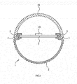
- FIG. 3 is a section view showing a LED tube with a voltage boosting circuit in an embodiment.
- a fitting recess 3 is formed inside a LED base 2 for fastening with a circuit board 5.
- An external heat dissipation seat 15 is configured at the outer of the LED base 2.
- An accommodating space 150 is formed in the LED tube for accommodating the LED base 2.
- the number of the LED lamp beads 14 configured on the circuit board 5 is 150 as an example.
- the LED tube 1 includes a LED base 2, a circuit board 5, a driving module 6 and a lampshade 15.
- the driving module 6 is a constant-current type.
- the circuit board 5 is disposed on the LED base 2.
- At least 50 LED lamp beads 14 connected in series are configured on the circuit board 5.
- the driving module 6 is electronically connected to the circuit board 5.
- the LED lamp beads 14 are excited with a high voltage and a low current.
- a lampshade 15 is configured on the LED base 2 to shield the circuit board 5.
- the constant-current driving module 12 is configured at any one or both sides of the LED tube according to requirements.
- the driving module 12 includes an alternating current (AC) filter module 7, a rectifier filter module 8, an enable module 9, a power supply module 10, a control module 11, an energy storage module 12, a voltage output module 13, and a current output module 14.
- AC alternating current
- the rectifier filter module 8 includes a plurality of diodes, a plurality of capacitors, and a plurality of inductors.
- the enable module 9 includes a plurality of the resistors, a plurality of the Metal-Oxide-Semiconductor (MOS), a plurality of diodes, and a plurality of capacitors.
- the power supply module 10 includes a plurality of diodes, a plurality of voltage regulator tubes, a plurality of capacitors, and a potential transformer.
- the control module 11 includes a plurality of resistors, a plurality of capacitors, and a plurality of diodes.
- the energy storage module 12 includes a potential transformer, a MOS, a plurality of the resistors.
- the voltage output module 13 includes a plurality of the resistors.
- the current output module 14 includes a plurality of resistors, a plurality of diodes, and a plurality of capacitors.
- a LED tube 1 in an embodiment is shown in FIG. 2 and FIG. 3 .
- a fitting recess 3 is formed inside a LED base 2 for fastening with a circuit board 5.
- a fastening slot 4 for fastening the lampshade 15 is configured at an outer side of the LED base 2.
- the driving module 6 includes an AC filter module 7, a rectifier filter module 8, an enable module 9, a power supply module 10, a control module 11, an energy storage module 12, a voltage output module 13, and a current output module 14.
- the rectifier filter module 8 includes a plurality of the diodes, a plurality of capacitors and inductors.
- the enable module 9 includes a plurality of the resistors, a plurality of MOS, diodes and a plurality of capacitors.
- the power supply module 10 includes diodes, a voltage regulator tube, capacitors and a potential transformer.
- the control module 11 includes a plurality of the resistors, a plurality of capacitors, and diodes.
- the energy storage module 12 includes a potential transformer, a MOS, a plurality of resistors.
- the voltage output module 13 includes a plurality of resistors .
- the current output module 14 includes a plurality of resistors, diodes, and capacitors.
- the MOS is conducted. With the current limit via a resistor of the enable module 9, the capacitor of the enable module 9 is charged. When a cross voltage of a capacitor of the enable module 9 is larger than a threshold voltage of the control module 11, the control module 11 is enabled. Via a resistor of the control module 11, a MOS of the energy storage module 12 is driven to switch on/off. Then, the duty cycle of the MOS is changed to control the potential transformer of the energy storage module 12 and the energy storage time of the inductor. The voltage of the output end of the LEDs is adjusted.
- the control module 11 When the control module 11enters the operation state, the control module 11 outputs a voltage signal, with the current limit via a resistor of the enable module 9, the MOS of the enable module 9 is driven to enter into a saturation conduction state. At the moment, the grid potential of another MOS of the enable module 9 is pulled down via the above MOS. The MOS which is changed from the conducted state to the cut off state stops the charging to the capacitors of the enable module 9. The charging of the control module 11 is changed.
- the auxiliary winding have the power supply to the capacitor of the enable module 9 via the current limit of the resistor and the capacitor of the power supply module 10, the rectification of the diodes, and the voltage stabilization of the voltage regulator tube.
- the control module 11 reduces the conduction time of the MOS. Otherwise, the control module 11 increases the conduction time of the MOS.
- the lamp beads are connected in series in a manner of high voltage and low current, the current transmission is consistent. The consistency and the efficient of the lamp beads are improved. The ripple is avoided, and the stroboflash is reduced.
- the LED lamp beads connected in series are configured on the substrate . With the constant current driving module, a high voltage is input and a low current is output to make each of the stimulated LED lamp beads have a same color temperature, a same service life, a high luminous efficiency, a low current conversion, and a low capacitors cost.
- the driving module 6 has a high voltage input and a low current output.
- the DC voltage is higher than 400V, via the voltage boosting circuit, the current becomes consist and the output voltage is increased.
- the filtering is performed after the voltage reduction.
- the low current is output to the circuit board 5 and excites the LED lamp beads 14.
- Each of the excited LED lamp beads has a same color temperature, a same service life. The luminous efficacy is improved, the current conversion is low, and the cost of the voltage output module is low.
- FIG. 4 is a section view showing a LED tube with a voltage boosting circuit in an embodiment.
- a LED tube with a voltage boosting circuit is provided.
- the LED tube 1 includes a LED base 2, a circuit board 5, a driving module 6, and a lampshade 15.
- the circuit board 5 is configured on the LED base 2.
- at least 50 LED lamp beads 14 connected in series are configured on the circuit board 5.
- the driving module 6 is electronically connected to the circuit board 5.
- the high voltage input and low voltage output excite the LED lamp beads 14.
- a lampshade 15 is configured on the LED base 2 to cover the circuit board 5.
- the voltage is divided to another resistor via the resistors of the voltage output module 13. After filtered, the current value sample voltage is obtained and transmitted to an internal testing end of the control module 11.
- the control module 11 reduces the conduction time of the MOS. Otherwise, the control module 11 increases the conduction time of the MOS.
- the control module 11 In the operation state, by measuring the voltage drop between two ends of the resistors of the current output module 14, and after the filtering via the resistors and capacitors, the voltage is output to the control module 11 the internal testing end. When the voltage is higher than the internal reference voltage, the control module 11 reduces the conduction time of the MOS. Otherwise, the control module 11 increases the conduction time of the MOS.
- a pulsation DC voltage is generated via the AC filter module 7 and the rectifier filter module 8.
- the enable module 9 is connected with an output end of the rectifier filter module 8 via a resistor of the enable module 9, and the voltage is divided to another MOS via other resistors of the enable module 9 to provide an enable voltage.
- FIG.1 to FIG. 4 Please refer to FIG.1 to FIG. 4 .
- the control module 11 When a cross voltage of a capacitor of the enable module 9 is larger than the threshold voltage of the control module 11, the control module 11 is enabled. Via a resistor of the control module 11, a MOS of the energy storage module 12 is driven to switch on/off. Then, the duty cycle of the MOS is changed to control the potential transformer of the energy storage module 12 and the energy storage time of the inductor. Then, the voltage of the output end of the LEDs is adjusted.
- the auxiliary winding have the power supply to the capacitor of the enable module 9 via the current limit of the resistor and the capacitor of the power supply module 10, the rectification of the diodes, and the voltage stabilization of the voltage regulator tube.
- 150 LED lamp beads connected in series are configured on the substrate 11. With the high voltage input and low voltage output, each of the excited LED lamp beads has a same color temperature. With the power supply larger than 400V, the efficient is improved, and the heat dissipation is reduced.
- the LED lamp beads With the voltage boosting circuit of the driving module, the LED lamp beads have a consistent current.
- the 150 LED lamp beads connected in series are configured on the circuit board 5.
- each of the excited LED lamp beads Via the driving module 6 with the high voltage input and low voltage output, each of the excited LED lamp beads has a same color temperature, a same service life. The luminous efficacy is improved, the current conversion is low, and the cost of the voltage output module is low.
Landscapes
- Engineering & Computer Science (AREA)
- Power Engineering (AREA)
- Physics & Mathematics (AREA)
- Microelectronics & Electronic Packaging (AREA)
- Optics & Photonics (AREA)
- General Engineering & Computer Science (AREA)
- Circuit Arrangement For Electric Light Sources In General (AREA)
- Non-Portable Lighting Devices Or Systems Thereof (AREA)
- Fastening Of Light Sources Or Lamp Holders (AREA)
Applications Claiming Priority (1)
| Application Number | Priority Date | Filing Date | Title |
|---|---|---|---|
| CN201710549807.4A CN107333354B (zh) | 2017-07-07 | 2017-07-07 | 具有增压电路的led灯管 |
Publications (1)
| Publication Number | Publication Date |
|---|---|
| EP3426005A1 true EP3426005A1 (de) | 2019-01-09 |
Family
ID=60196410
Family Applications (1)
| Application Number | Title | Priority Date | Filing Date |
|---|---|---|---|
| EP18170430.5A Withdrawn EP3426005A1 (de) | 2017-07-07 | 2018-05-02 | Led-röhre mit spannungserhöhungsschaltung |
Country Status (4)
| Country | Link |
|---|---|
| US (1) | US20190014639A1 (de) |
| EP (1) | EP3426005A1 (de) |
| JP (1) | JP2019016581A (de) |
| CN (1) | CN107333354B (de) |
Families Citing this family (4)
| Publication number | Priority date | Publication date | Assignee | Title |
|---|---|---|---|---|
| JP2020167134A (ja) * | 2019-03-31 | 2020-10-08 | 厦門普為光電科技有限公司 | 回転コネクタ及び反射シートを備える照明装置 |
| CN110360477A (zh) * | 2019-07-23 | 2019-10-22 | 广东自由之光照明实业有限公司 | 一种长距离传输线条灯 |
| CN113446524B (zh) * | 2020-03-27 | 2026-02-27 | 晨辉光宝科技股份有限公司 | 带开关和/或指示灯的led直管灯 |
| USD993476S1 (en) * | 2020-05-22 | 2023-07-25 | Xiamen Fulaishi Film Tools Co., Ltd. | Tube light for photography and video |
Citations (4)
| Publication number | Priority date | Publication date | Assignee | Title |
|---|---|---|---|---|
| US20100033095A1 (en) * | 2008-02-08 | 2010-02-11 | Innosys, Inc. | Solid State Semiconductor LED Replacement for Fluorescent Lamps |
| WO2013090945A1 (en) * | 2011-12-16 | 2013-06-20 | Advanced Lighting Technologies, Inc. | Near unity power factor long life low cost led lamp retrofit system and method |
| WO2015128388A1 (en) * | 2014-02-26 | 2015-09-03 | Koninklijke Philips N.V. | Driver arrangement |
| US20160128157A1 (en) * | 2014-11-04 | 2016-05-05 | Richard P. Ulivella | Modular solid state lighting apparatus platform with local and remote microprocessor control |
Family Cites Families (15)
| Publication number | Priority date | Publication date | Assignee | Title |
|---|---|---|---|---|
| US7049761B2 (en) * | 2000-02-11 | 2006-05-23 | Altair Engineering, Inc. | Light tube and power supply circuit |
| US9516706B2 (en) * | 2006-02-09 | 2016-12-06 | Led Smart Inc. | LED lighting system |
| RU2503883C2 (ru) * | 2007-09-07 | 2014-01-10 | Филипс Солид-Стейт Лайтинг Солюшнз, Инк. | Способы и устройства для обеспечения прожекторного освещения на основе светоизлучающих диодов в приложениях для освещения сцены |
| JP3148721U (ja) * | 2008-12-11 | 2009-02-26 | 株式会社サンテック | Led照明装置 |
| CN202195329U (zh) * | 2011-07-28 | 2012-04-18 | 陈卫平 | 一种用来取代t5直管荧光灯的led灯管 |
| JP2013118130A (ja) * | 2011-12-05 | 2013-06-13 | Panasonic Corp | 点灯装置および照明器具 |
| CN102588790A (zh) * | 2012-02-18 | 2012-07-18 | 施杲宇 | 可拆卸模块式智能人体感应led灯管 |
| US20140159603A1 (en) * | 2012-12-07 | 2014-06-12 | Samsung Electro-Mechanics Co., Ltd. | Led driving apparatus and method |
| CN202955541U (zh) * | 2012-12-11 | 2013-05-29 | 厦门普为光电科技有限公司 | 大发光角led灯管 |
| CN203181318U (zh) * | 2013-04-15 | 2013-09-04 | 阮雪芬 | 双半桥注入锁相发光二极管led阵列灯 |
| JP2014207206A (ja) * | 2013-04-16 | 2014-10-30 | エコ・トラスト・ジャパン株式会社 | 直管型led照明 |
| JP2017004611A (ja) * | 2015-06-04 | 2017-01-05 | 株式会社リコー | 照明灯、照明装置、点灯制御回路、および照明灯の駆動方法 |
| US9730289B1 (en) * | 2016-02-08 | 2017-08-08 | Cree, Inc. | Solid state light fixtures having ultra-low dimming capabilities and related driver circuits and methods |
| CN106102206B (zh) * | 2016-05-28 | 2019-06-28 | 李宗凤 | 灯用驱动电源 |
| CN106793315A (zh) * | 2016-12-29 | 2017-05-31 | 铜陵迈维电子科技有限公司 | Led智能恒流恒压驱动电源 |
-
2017
- 2017-07-07 CN CN201710549807.4A patent/CN107333354B/zh active Active
- 2017-08-09 JP JP2017153860A patent/JP2019016581A/ja active Pending
- 2017-10-17 US US15/786,581 patent/US20190014639A1/en not_active Abandoned
-
2018
- 2018-05-02 EP EP18170430.5A patent/EP3426005A1/de not_active Withdrawn
Patent Citations (4)
| Publication number | Priority date | Publication date | Assignee | Title |
|---|---|---|---|---|
| US20100033095A1 (en) * | 2008-02-08 | 2010-02-11 | Innosys, Inc. | Solid State Semiconductor LED Replacement for Fluorescent Lamps |
| WO2013090945A1 (en) * | 2011-12-16 | 2013-06-20 | Advanced Lighting Technologies, Inc. | Near unity power factor long life low cost led lamp retrofit system and method |
| WO2015128388A1 (en) * | 2014-02-26 | 2015-09-03 | Koninklijke Philips N.V. | Driver arrangement |
| US20160128157A1 (en) * | 2014-11-04 | 2016-05-05 | Richard P. Ulivella | Modular solid state lighting apparatus platform with local and remote microprocessor control |
Also Published As
| Publication number | Publication date |
|---|---|
| JP2019016581A (ja) | 2019-01-31 |
| CN107333354B (zh) | 2020-07-10 |
| CN107333354A (zh) | 2017-11-07 |
| US20190014639A1 (en) | 2019-01-10 |
Similar Documents
| Publication | Publication Date | Title |
|---|---|---|
| JP5076106B2 (ja) | 高効率ac led駆動回路 | |
| US8242703B2 (en) | Driving apparatus for light emitting diodes without employing electrolytic capacitor | |
| US9326336B2 (en) | Dual switcher flyback structure for LED driver | |
| US9497814B2 (en) | Driver device and driving method for driving a load, in particular an LED unit | |
| EP2348794B1 (de) | Wechselstrom-LED-Lampe | |
| US10602597B1 (en) | Solid-state lighting with a reduced temporal light artifact | |
| EP3426005A1 (de) | Led-röhre mit spannungserhöhungsschaltung | |
| EP2424332A1 (de) | Gleichstromquelleneinheit und LED-Lampensystem | |
| CN104813742A (zh) | 电源电压管理 | |
| US20100244703A1 (en) | Ac-driven led lighting device | |
| KR20110136537A (ko) | 과전압 보호와 정전류 구동을 위한 led 구동 회로 및 방법 | |
| US11330688B2 (en) | Solid-state lighting with reduced light flickering | |
| US10334673B2 (en) | Lighting system | |
| US20170311401A1 (en) | Light emitting device | |
| JP2008218150A (ja) | 照明装置および制御回路 | |
| KR101434110B1 (ko) | 싱글 스테이지 포워드-플라이백 컨버터, 전원 공급 장치 및 발광 다이오드용 전원 공급 장치 | |
| JP5551995B2 (ja) | 電源装置及びこの電源装置を備えた照明装置 | |
| CN212413481U (zh) | 降压调光驱动电路 | |
| US8519638B2 (en) | Electronic ballast for a high intesity discharge lamp | |
| US20160057821A1 (en) | Illumination Module | |
| KR101839052B1 (ko) | 전력 변환 장치 | |
| TWM553090U (zh) | 照明系統 | |
| US20160102818A1 (en) | Led-based lighting module using slow decay phosphor to reduce flicker | |
| KR101382708B1 (ko) | 전원공급회로 | |
| JP3188404U (ja) | 照明装置 |
Legal Events
| Date | Code | Title | Description |
|---|---|---|---|
| PUAI | Public reference made under article 153(3) epc to a published international application that has entered the european phase |
Free format text: ORIGINAL CODE: 0009012 |
|
| AK | Designated contracting states |
Kind code of ref document: A1 Designated state(s): AL AT BE BG CH CY CZ DE DK EE ES FI FR GB GR HR HU IE IS IT LI LT LU LV MC MK MT NL NO PL PT RO RS SE SI SK SM TR |
|
| AX | Request for extension of the european patent |
Extension state: BA ME |
|
| STAA | Information on the status of an ep patent application or granted ep patent |
Free format text: STATUS: THE APPLICATION IS DEEMED TO BE WITHDRAWN |
|
| 18D | Application deemed to be withdrawn |
Effective date: 20190710 |