EP3426532B1 - Réservoir de frein à conduit interne pour unité de servofrein intégrée - Google Patents
Réservoir de frein à conduit interne pour unité de servofrein intégrée Download PDFInfo
- Publication number
- EP3426532B1 EP3426532B1 EP17710189.6A EP17710189A EP3426532B1 EP 3426532 B1 EP3426532 B1 EP 3426532B1 EP 17710189 A EP17710189 A EP 17710189A EP 3426532 B1 EP3426532 B1 EP 3426532B1
- Authority
- EP
- European Patent Office
- Prior art keywords
- chamber
- sub
- reservoir
- fluid reservoir
- outlet port
- Prior art date
- Legal status (The legal status is an assumption and is not a legal conclusion. Google has not performed a legal analysis and makes no representation as to the accuracy of the status listed.)
- Active
Links
Images


Classifications
-
- B—PERFORMING OPERATIONS; TRANSPORTING
- B60—VEHICLES IN GENERAL
- B60T—VEHICLE BRAKE CONTROL SYSTEMS OR PARTS THEREOF; BRAKE CONTROL SYSTEMS OR PARTS THEREOF, IN GENERAL; ARRANGEMENT OF BRAKING ELEMENTS ON VEHICLES IN GENERAL; PORTABLE DEVICES FOR PREVENTING UNWANTED MOVEMENT OF VEHICLES; VEHICLE MODIFICATIONS TO FACILITATE COOLING OF BRAKES
- B60T13/00—Transmitting braking action from initiating means to ultimate brake actuator with power assistance or drive; Brake systems incorporating such transmitting means, e.g. air-pressure brake systems
- B60T13/10—Transmitting braking action from initiating means to ultimate brake actuator with power assistance or drive; Brake systems incorporating such transmitting means, e.g. air-pressure brake systems with fluid assistance, drive, or release
- B60T13/12—Transmitting braking action from initiating means to ultimate brake actuator with power assistance or drive; Brake systems incorporating such transmitting means, e.g. air-pressure brake systems with fluid assistance, drive, or release the fluid being liquid
- B60T13/14—Transmitting braking action from initiating means to ultimate brake actuator with power assistance or drive; Brake systems incorporating such transmitting means, e.g. air-pressure brake systems with fluid assistance, drive, or release the fluid being liquid using accumulators or reservoirs fed by pumps
-
- B—PERFORMING OPERATIONS; TRANSPORTING
- B60—VEHICLES IN GENERAL
- B60T—VEHICLE BRAKE CONTROL SYSTEMS OR PARTS THEREOF; BRAKE CONTROL SYSTEMS OR PARTS THEREOF, IN GENERAL; ARRANGEMENT OF BRAKING ELEMENTS ON VEHICLES IN GENERAL; PORTABLE DEVICES FOR PREVENTING UNWANTED MOVEMENT OF VEHICLES; VEHICLE MODIFICATIONS TO FACILITATE COOLING OF BRAKES
- B60T11/00—Transmitting braking action from initiating means to ultimate brake actuator without power assistance or drive or where such assistance or drive is irrelevant
- B60T11/10—Transmitting braking action from initiating means to ultimate brake actuator without power assistance or drive or where such assistance or drive is irrelevant transmitting by fluid means, e.g. hydraulic
- B60T11/26—Reservoirs
-
- B—PERFORMING OPERATIONS; TRANSPORTING
- B60—VEHICLES IN GENERAL
- B60T—VEHICLE BRAKE CONTROL SYSTEMS OR PARTS THEREOF; BRAKE CONTROL SYSTEMS OR PARTS THEREOF, IN GENERAL; ARRANGEMENT OF BRAKING ELEMENTS ON VEHICLES IN GENERAL; PORTABLE DEVICES FOR PREVENTING UNWANTED MOVEMENT OF VEHICLES; VEHICLE MODIFICATIONS TO FACILITATE COOLING OF BRAKES
- B60T13/00—Transmitting braking action from initiating means to ultimate brake actuator with power assistance or drive; Brake systems incorporating such transmitting means, e.g. air-pressure brake systems
- B60T13/10—Transmitting braking action from initiating means to ultimate brake actuator with power assistance or drive; Brake systems incorporating such transmitting means, e.g. air-pressure brake systems with fluid assistance, drive, or release
- B60T13/12—Transmitting braking action from initiating means to ultimate brake actuator with power assistance or drive; Brake systems incorporating such transmitting means, e.g. air-pressure brake systems with fluid assistance, drive, or release the fluid being liquid
- B60T13/14—Transmitting braking action from initiating means to ultimate brake actuator with power assistance or drive; Brake systems incorporating such transmitting means, e.g. air-pressure brake systems with fluid assistance, drive, or release the fluid being liquid using accumulators or reservoirs fed by pumps
- B60T13/142—Systems with master cylinder
-
- B—PERFORMING OPERATIONS; TRANSPORTING
- B60—VEHICLES IN GENERAL
- B60T—VEHICLE BRAKE CONTROL SYSTEMS OR PARTS THEREOF; BRAKE CONTROL SYSTEMS OR PARTS THEREOF, IN GENERAL; ARRANGEMENT OF BRAKING ELEMENTS ON VEHICLES IN GENERAL; PORTABLE DEVICES FOR PREVENTING UNWANTED MOVEMENT OF VEHICLES; VEHICLE MODIFICATIONS TO FACILITATE COOLING OF BRAKES
- B60T13/00—Transmitting braking action from initiating means to ultimate brake actuator with power assistance or drive; Brake systems incorporating such transmitting means, e.g. air-pressure brake systems
- B60T13/10—Transmitting braking action from initiating means to ultimate brake actuator with power assistance or drive; Brake systems incorporating such transmitting means, e.g. air-pressure brake systems with fluid assistance, drive, or release
- B60T13/12—Transmitting braking action from initiating means to ultimate brake actuator with power assistance or drive; Brake systems incorporating such transmitting means, e.g. air-pressure brake systems with fluid assistance, drive, or release the fluid being liquid
- B60T13/14—Transmitting braking action from initiating means to ultimate brake actuator with power assistance or drive; Brake systems incorporating such transmitting means, e.g. air-pressure brake systems with fluid assistance, drive, or release the fluid being liquid using accumulators or reservoirs fed by pumps
- B60T13/148—Arrangements for pressure supply
-
- B—PERFORMING OPERATIONS; TRANSPORTING
- B60—VEHICLES IN GENERAL
- B60T—VEHICLE BRAKE CONTROL SYSTEMS OR PARTS THEREOF; BRAKE CONTROL SYSTEMS OR PARTS THEREOF, IN GENERAL; ARRANGEMENT OF BRAKING ELEMENTS ON VEHICLES IN GENERAL; PORTABLE DEVICES FOR PREVENTING UNWANTED MOVEMENT OF VEHICLES; VEHICLE MODIFICATIONS TO FACILITATE COOLING OF BRAKES
- B60T13/00—Transmitting braking action from initiating means to ultimate brake actuator with power assistance or drive; Brake systems incorporating such transmitting means, e.g. air-pressure brake systems
- B60T13/74—Transmitting braking action from initiating means to ultimate brake actuator with power assistance or drive; Brake systems incorporating such transmitting means, e.g. air-pressure brake systems with electrical assistance or drive
- B60T13/745—Transmitting braking action from initiating means to ultimate brake actuator with power assistance or drive; Brake systems incorporating such transmitting means, e.g. air-pressure brake systems with electrical assistance or drive acting on a hydraulic system, e.g. a master cylinder
-
- B—PERFORMING OPERATIONS; TRANSPORTING
- B60—VEHICLES IN GENERAL
- B60T—VEHICLE BRAKE CONTROL SYSTEMS OR PARTS THEREOF; BRAKE CONTROL SYSTEMS OR PARTS THEREOF, IN GENERAL; ARRANGEMENT OF BRAKING ELEMENTS ON VEHICLES IN GENERAL; PORTABLE DEVICES FOR PREVENTING UNWANTED MOVEMENT OF VEHICLES; VEHICLE MODIFICATIONS TO FACILITATE COOLING OF BRAKES
- B60T8/00—Arrangements for adjusting wheel-braking force to meet varying vehicular or ground-surface conditions, e.g. limiting or varying distribution of braking force
- B60T8/32—Arrangements for adjusting wheel-braking force to meet varying vehicular or ground-surface conditions, e.g. limiting or varying distribution of braking force responsive to a speed condition, e.g. acceleration or deceleration
- B60T8/34—Arrangements for adjusting wheel-braking force to meet varying vehicular or ground-surface conditions, e.g. limiting or varying distribution of braking force responsive to a speed condition, e.g. acceleration or deceleration having a fluid pressure regulator responsive to a speed condition
- B60T8/40—Arrangements for adjusting wheel-braking force to meet varying vehicular or ground-surface conditions, e.g. limiting or varying distribution of braking force responsive to a speed condition, e.g. acceleration or deceleration having a fluid pressure regulator responsive to a speed condition comprising an additional fluid circuit including fluid pressurising means for modifying the pressure of the braking fluid, e.g. including wheel driven pumps for detecting a speed condition, or pumps which are controlled by means independent of the braking system
- B60T8/4072—Systems in which a driver input signal is used as a control signal for the additional fluid circuit which is normally used for braking
- B60T8/4077—Systems in which the booster is used as an auxiliary pressure source
Definitions
- the present invention relates to vehicle braking systems, and more particularly to a fluid reservoir construction for an integrated power brake unit (IPB).
- IPB integrated power brake unit
- DE 28 34 789 A1 describes a brake fluid reservoir comprising two separated chambers that are connected to one another via an opening.
- JP 2008 149801 A discloses a brake fluid reservoir comprising two chambers connected via an opening, wherein a filter is provided at the opening.
- EP 1441 939 A1 describes a brake system with a brake fluid reservoir comprising a first chamber with a first port for supplying fluid to a primary hydraulic circuit of a master cylinder, a second chamber with a second port for supplying fluid to a secondary hydraulic circuit of the master cylinder, and a third chamber with a third port for supplying fluid to a pump.
- DE 103 46 236 A1 describes a brake-by-wire brake system with a brake fluid reservoir that comprises three chambers.
- the invention provides an integrated power brake unit, including an input rod operable to receive a driver braking input force, a booster operable to boost the driver braking input force, a master cylinder, a pump operable to provide pressurized fluid for braking, in lieu of the master cylinder, in response to the driver braking input force, and a fluid reservoir defining a main chamber.
- the fluid reservoir has first and second outlet ports in fluid communication to supply the master cylinder, and a third outlet port in fluid communication to supply the pump, each of the first, second, and third outlet ports being provided in a bottom wall of the fluid reservoir.
- the fluid reservoir includes a sub-chamber within the main chamber, the sub-chamber covering the third outlet port, and defining an opening to the main chamber at a forward-most end of the sub-chamber.
- the invention provides a brake fluid reservoir for a vehicle.
- the brake fluid reservoir includes an outer shell defining a main chamber for containing a quantity of brake fluid for one or more vehicle brake circuits, a cap attachable to an opening in an upper wall of the outer shell to close the main chamber from the surrounding environment, and an outlet port provided on a bottom wall of the outer shell.
- An enclosed sub-chamber is defined within the main chamber and directly surrounding the outlet port.
- An opening between the sub-chamber and the main chamber is spaced forwardly of the outlet port to maintain unbroken fluid communication between the main chamber and the sub-chamber directly surrounding the outlet port in a condition in which fluid volume in the main chamber covers the opening but does not cover the outlet port.
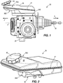
- the IPB unit 20 includes a housing or block 24 that contains both a brake booster (e.g., an electromechanical booster) and a brake master cylinder with outlet ports for supplying pressurized brake fluid to one or more brake circuits that contain one or more wheel cylinders to apply braking force to a wheel (e.g., squeezing a brake disc fixed to the wheel).
- the IPB unit 20 further includes an electronic controller coupled to a series of electronically-controlled valves inside the block 24, programmed to carry out anti-lock braking (ABS) performance strategy and/or electronic stability control (ESC) strategy.
- An electric motor 28 is coupled to the block 24 and has an output inside the block 24 operable to run at least one pump to generate a flow of pressurized brake fluid.
- the IPB unit 20 has a defined orientation for mounting within a vehicle as defined by a brake input rod 30 that extends in a rearward direction R.
- the IPB unit 20 is mounted in the engine bay or under-hood area of the vehicle near or on the dash wall, with the brake input rod 30 extending toward a cabin space of the vehicle so that the brake input rod 30 is coupled to a driver-actuated brake pedal (not shown).
- a forward direction F Opposite the rearward direction R is a forward direction F, which is consistent with a normal forward travel direction of the vehicle.
- the IPB unit 20 can operate in a full decoupled or brake-by-wire (BBW) mode in which braking force is generated by an electromechanical device (e.g., a motor-driven pump) that delivers fluid into the brake circuits with electronic pressure control (e.g., via an electronically-controlled pressure control valve), without utilizing pressure generated in the master cylinder by the brake input rod 30.
- BBW brake-by-wire
- the IPB unit 20 can also function to provide non-driver-directed braking, or "active" braking, such as the case with adaptive cruise control or autonomous emergency braking in response to one or more types of vehicle sensors.
- a brake fluid reservoir 36 Adjacent a top side of the IPB unit 20 is a brake fluid reservoir 36 operable to store a quantity of hydraulic brake fluid to ensure that the braking circuits have a reserve quantity of fluid to draw from during braking operations.
- the reservoir 36 particularly an outer shell of the reservoir 36, defines a reservoir chamber and includes an upper portion 38 with a fill opening normally closed by a reservoir cap 40.
- the reservoir 36 includes upper and lower portions bonded together at a peripheral seam 41.
- the reservoir 36 has a shape, dictated by specific vehicle packaging constraints, that has a relatively low height at the rearward side, and a relatively high height at the forward side.
- the respective heights can be measured upwardly, orthogonal to a top surface 24A of the block 24, or alternately measured upwardly from a plane P in which the brake input rod 30 is located.
- the plane P is horizontal as illustrated in Fig. 1 .
- the IPB unit 20 has a defined orientation with respect to top and bottom, in which the reservoir 36 is positioned atop and is coupled to the top surface 24A of the block 24 (a so-called "top-mount" reservoir).
- the forward-most portion of the reservoir 36 can define an upper shelf portion 36A of the chamber.
- the upper shelf portion 36A has a bottom surface 36B positioned at a height above a bottom wall 48 of the reservoir 36 where the reservoir 36 connects to the block 24, and the master cylinder therein.
- the bottom wall 48 of the reservoir 36 is provided with one or more outlet ports P1, P2 corresponding to respective master cylinder inlet ports.
- An additional outlet port, or "active port” P3, is separately provided in the bottom wall 48 of the reservoir 36 for connection to an active braking inlet port of the block 24.
- active port P3 is indicative of an open system (or "open circuit") configuration where the active boosting circuit and stability controlled circuit is always in fluid communication with the reservoir 36, as opposed to a closed system configuration (or “closed circuit”) in which the reservoir and the circuit are fluidly isolated when activated in its normal operation.
- Non-limiting, detailed examples of braking systems with an open circuit configuration can be found in U.S. Patent 9,315,182 .
- U.S. Patent 9,315,182 During operation of the vehicle, it is important to ensure that inlets into the block 24 are continuously bathed in fluid to prevent air from being entrained and introducing compressibility to the braking circuits. This is normally achieved by the design of the reservoir 36 and the placement of the reservoir outlet ports P1, P2, P3 to ensure that the reservoir outlet ports P1, P2, P3 cannot lose fluid coverage at any point during an established set of design parameters, which can include maximum design vehicle deceleration.
- this proves to be increasingly difficult.
- the reservoir 36 of Figs. 1-6 includes a sub-chamber 42 within the reservoir chamber that improves the condition of port coverage with brake fluid in adverse vehicle maneuvers, ensuring that the active port P3 remains continuously bathed in fluid, even in circumstances of maximum vehicle deceleration, which tends to shift all the fluid in the reservoir 36 in the forward direction F, or cresting a hill at high speed, which tends to shift all the fluid in the reservoir 36 upward.
- a typical automobile will be able to decelerate and maintain a force that will send the brake fluid in the reservoir 36 towards the forward direction F to a degree that, without the sub-chamber 42, would break fluid coverage of at least the active port P3, which is the rearmost of the reservoir outlet ports.
- the sub-chamber 42 ensures that, under all driving conditions, including maximum design deceleration of the vehicle, the active port P3 has access to a predefined volume charge of fluid.
- the addition of the sub-chamber 42 allows for sufficient brake fluid depth at the active port P3, so as to minimize or eliminate the risk of air intake during adverse maneuvers.
- the sub-chamber 42 can define a volume that is at least great enough to supply a full circuit charge.
- the sub-chamber 42 can define a volume of at least 20cc and not more than 30cc (e.g., 25cc in one exemplary embodiment).
- the addition of the sub-chamber 42 accomplishes these objectives without requiring the active port P3 to be located in a central or forward portion of the reservoir 36.
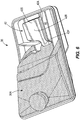
- the active port P3 can be located in the rear third of, or even the rear fifth of, a longitudinal reservoir length L as measured front-to-rear (see Fig. 5 ).
- the length L 3 from a rear edge of the reservoir main chamber to the active port P3 can be one-third or less than the length L of the reservoir main chamber, and in some cases L 3 is one-fifth or less than the length L of the reservoir main chamber.
- the brake fluid reservoir 36 can be made from polypropylene and constructed of two halves that are high temperature welded so that leakage during brake system filing and normal usage is avoided.
- the sub-chamber 42 in the lower half of the reservoir 36 is implemented by another weld or bonding operation prior to bringing the top and bottom halves together for the final weld operation.
- the sub-chamber 42 can be formed by one or more upstanding walls 42A extending upward from the bottom wall 48 as shown in Fig. 3 .
- the walls 42A can be integrally-formed (e.g., by a common molding process) with the bottom wall 48 in some constructions, eliminating the need to bond the upstanding walls 42A to the bottom wall 48.
- the sub-chamber 42 can further be enclosed on a top side by a cover 42B as shown in Fig. 4 (the cover 42B is removed in Fig. 3 to illustrate the interior of the sub-chamber 42.
- the cover 42B can be bonded or welded to the top edge of the upstanding walls 42A to seal the sub-chamber 42 from the surrounding volume of the reservoir 36.
- the sub-chamber 42 can be completely enclosed and sealed from the reservoir chamber except for a small opening 56 provided at a forward end 42F of the sub-chamber 42.
- the opening 56 is provided in the cover 42B.
- the opening 56 is positioned at a central portion of the reservoir chamber as measured front-to-rear.
- the sub-chamber 42 is formed in two sections, including a main or major portion 42R that is located rearward of the opening 56 and that defines a majority of the sub-chamber volume and directly surrounds the active port P3.
- the other section of the sub-chamber 42 is a stem portion 42F extending forwardly from the rearward major portion 43R and including the opening 56 at its forward-most end.
- the stem portion 42F extends both forwardly and laterally from the major portion 42R.
- the opening 56 can be provided at a height above the active port P3, which is provided at the bottom of the rearward major portion 42R of the sub-chamber 42.
- the opening 56 can be provided in a downwardly-tapered section 42T of the cover 42B.
- the opening 56 can be positioned directly adjacent in height to the bottom wall 48 of the reservoir 36 so that flow between the main reservoir chamber and the sub-chamber 42 is largely unobstructed. This can be accomplished by providing the downwardly-tapered section 42T and the opening 56 adjacent an area of the bottom wall 48 that is higher than that where the rearward major portion 42R of the sub-chamber 42 is located.
- the bottom wall 48 cascades downwardly from the forward stem portion 42F to the rearward major portion 42R of the sub-chamber 42.
- the upstanding walls 42A that define the perimeter of the sub-chamber 42 may have little or no protrusion from the bottom wall 48 at the forwardmost end of the stem portion 42F as the bottom wall 48 and the sub-chamber walls 42A merge closely together at a common height.
- the sub-chamber 42 serves as an extension of the active port P3 that extends closer to the center of the reservoir 36 to provide more coverage of brake fluid during adverse vehicle maneuvers where the fluid rushes to one side or the other.
- An example of brake fluid movement within the reservoir 36 during a maximum braking deceleration maneuver is shown in Figs. 5 and 6 . It is noted that this deceleration may correspond to a vehicle design criteria that may take into account the vehicle's original equipment braking equipment, and maximum available grip between the vehicle's original equipment tires and a dry road surface. It can be observed that the opening 56 remains fully covered in brake fluid despite the overall forward shift of the bulk brake fluid.
- fluid coverage can also be maintained over both the outlet ports P1, P2 to the master cylinder.
- the IPB unit 20 is designed to place the reservoir 36 in very close proximity to the dash. As a result, the available vertical package space for a reservoir design within a given vehicle application is significantly reduced.
- the addition of the sub-chamber42 in the reservoir 36 allows for the active port P3 to be fully covered with brake fluid at all times during normal operation of the vehicle. Without the sub-chamber 42, it would be nearly impossible to implement a top-mounted reservoir solution with the packaging constraints of the reservoir 36 as shown.
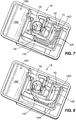
- Figs. 7 and 8 illustrate an alternate reservoir 136 that can be used with the IPB 20 or a similar unit.
- the reservoir 136 of Figs. 7 and 8 includes, similar to the reservoir 36 of Figs. 1-6 , a forward-most portion that defines an upper shelf portion 136A having a bottom surface 136B positioned at a height above a bottom wall 148 of the reservoir 136.
- a sub-chamber 142 is provided to surround the active port P3 as in the embodiment of Figs. 1-6 .
- the sub-chamber 142 is formed as a directed channel that includes a series of upstanding walls 142A arranged generally in an "L" shape, having two straight segments connected by a curved connection segment.
- the active port P3 is positioned at a rearward end 142R of the sub-chamber 142, opposite a forward end 142F.
- a cover 142B is bonded or welded to the top edge of the walls 142A to seal the sub-chamber 142.
- the sub-chamber 142 can be enclosed on four sides including top, bottom and both lateral sides along the entire length between its forward and rearward ends 142F, 142R.
- the sub-chamber 142 is only open to the main reservoir chamber at an opening 156 provided at the forward end 142F.
- the opening 156 is positioned at a central portion of the reservoir chamber as measured front-to-rear.
- the opening 156 can be formed in a wall extending up from the reservoir bottom wall 148 to define a level sensor sub-chamber 152 that receives a float assembly operable to indicate brake fluid level within the reservoir (i.e., required for dash warning light activation).
- each of the sub-chambers 42, 142 is provided to encompass the active outlet port P3 through which fluid communication, in an open system configuration, from the reservoir chamber to an active circuit is maintained during active braking.
- a sub-chamber as disclosed herein may be provided within a traditional master cylinder where fluid coverage at the reservoir ports into the master cylinder chambers is desired, and the proximity to the level sensor sub-chamber requires an enclosed volume that precludes the possibility for air intrusion into the system during extreme conditions where fluid moves in the main reservoir chamber.
Landscapes
- Engineering & Computer Science (AREA)
- Transportation (AREA)
- Mechanical Engineering (AREA)
- Physics & Mathematics (AREA)
- Fluid Mechanics (AREA)
- Transmission Of Braking Force In Braking Systems (AREA)
- Valves And Accessory Devices For Braking Systems (AREA)
- Braking Systems And Boosters (AREA)
Claims (20)
- Unité de servofrein intégrée (20) comprenant :une tige d'entrée (30) pouvant fonctionner pour recevoir une force d'entrée de freinage de conducteur ;un amplificateur pouvant fonctionner pour amplifier la force d'entrée de freinage de conducteur ;un maître-cylindre ;une pompe pouvant fonctionner pour fournir un fluide sous pression pour le freinage, au lieu du maître-cylindre, en réponse à la force d'entrée de freinage de conducteur ; etun réservoir de fluide (36 ; 136) définissant une chambre principale, le réservoir de fluide ayant des premier et deuxième orifices de sortie (P1, P2) en communication fluidique pour alimenter le maître-cylindre, et un troisième orifice de sortie (P3) en communication fluidique pour alimenter la pompe, chacun parmi les premier, deuxième et troisième orifices de sortie (P1, P2, P3) étant prévu dans une paroi inférieure (48 ; 148) du réservoir de fluide (36 ; 136),caractérisée en ce quele réservoir de fluide (36 ; 136) comporte une sous-chambre (42 ; 142) à l'intérieur de la chambre principale, la sous-chambre (42 ; 142) recouvrant le troisième orifice de sortie (P3), et définissant une ouverture (56 ; 156) vers la chambre principale au niveau d'une extrémité la plus à l'avant de la sous-chambre (42 ; 142).
- Unité de servofrein intégrée (20) selon la revendication 1, dans laquelle l'amplificateur est un amplificateur électromécanique.
- Unité de servofrein intégrée (20) selon la revendication 1, dans laquelle le troisième orifice de sortie (P3) est positionné à l'arrière des premier et deuxième orifices de sortie (P1, P2).
- Unité de servofrein intégrée (20) selon la revendication 1, dans laquelle le troisième orifice de sortie (P) est positionné dans le tiers arrière de la longueur de réservoir (L) telle que mesurée dans la direction d'avant en arrière.
- Unité de servofrein intégrée (20) selon la revendication 1, dans laquelle le troisième orifice de sortie (P3) est positionné dans le cinquième arrière de la longueur de réservoir (L) telle que mesurée dans la direction d'avant en arrière.
- Unité de servofrein intégrée (20) selon la revendication 1, dans laquelle le réservoir de fluide (136) comporte une sous-chambre (152) de capteur de niveau, et l'ouverture (156) du canal fermé est reliée à la sous-chambre de capteur de niveau.
- Unité de servofrein intégrée (20) selon la revendication 1, dans laquelle la sous-chambre (42) est formée à partir d'une partie tige avant (42F) et d'une partie principale arrière (42R), dans laquelle la partie principale arrière (42R) définit une majorité du volume de la sous-chambre et entoure directement le troisième orifice de sortie (P3), et dans laquelle l'ouverture (56) vers la chambre principale du réservoir de fluide est définie dans la partie tige (42F) .
- Unité de servofrein intégrée (20) selon la revendication 7, dans laquelle, à l'intérieur de la sous-chambre (42), la paroi inférieure (48) descend en cascade à partir de la partie tige avant (42F) jusqu'à la partie principale arrière (42R) de la sous-chambre (42) .
- Unité de servofrein intégrée (20) selon la revendication 7, dans laquelle la sous-chambre (42) comporte une pluralité de parois verticales (42A) s'étendant à partir de la paroi inférieure (48) et un couvercle (42B) installé de manière étanche sur la pluralité de parois verticales (42A), dans laquelle l'ouverture (56) vers la chambre principale du réservoir de fluide (36) est définie dans le couvercle (42B).
- Unité de servofrein intégrée (20) selon la revendication 9, dans laquelle l'ouverture (56) vers la chambre principale du réservoir de fluide (36) est définie dans une section (42T) s'amincissant vers le bas du couvercle (42B).
- Unité de servofrein intégrée (20) selon la revendication 1, dans laquelle la sous-chambre (42 ; 142) comporte une pluralité de parois verticales (42A ; 142A) formées d'un seul tenant avec la paroi inférieure (48 ; 148) de manière à s'étendre vers le haut à partir de celle-ci, et un couvercle (42B ; 142B) installé de manière étanche sur la pluralité de parois verticales (42A ; 142A).
- Unité de servofrein intégrée (20) selon la revendication 1, dans laquelle la sous-chambre (42 ; 142) ne renferme ni le premier ni le deuxième orifice de sortie (P1, P2).
- Réservoir de liquide de frein (36 ; 136) pour un véhicule, le réservoir de liquide de frein (36 ; 136) comprenant :une coque extérieure définissant une chambre principale destinée à contenir une quantité de liquide de frein pour un ou plusieurs circuits de frein de véhicule ;un bouchon (40) pouvant être fixé à une ouverture dans une paroi supérieure (38) de la coque extérieure pour fermer la chambre principale par rapport à l'environnement environnant ;un orifice de sortie (P3) prévu sur une paroi inférieure (48 ; 148) de la coque extérieure ;caractérisé en ce qu'il comprendune sous-chambre fermée (42 ; 142) définie à l'intérieur de la chambre principale et entourant directement l'orifice de sortie (P3), une ouverture (56 ; 156) entre la sous-chambre (42 ; 142) et la chambre principale étant espacée à l'avant de l'orifice de sortie (P3) pour maintenir une communication fluidique non interrompue entre la chambre principale et la sous-chambre (42 ; 142) entourant directement l'orifice de sortie (P3) dans un état dans lequel le volume de fluide dans la chambre principale recouvre l'ouverture (56 ; 156) mais ne recouvre pas l'orifice de sortie (P3) .
- Réservoir de liquide de frein (36 ; 136) selon la revendication 13, dans lequel l'orifice de sortie (P3) est positionné dans le tiers arrière de la longueur de réservoir (L) telle que mesurée dans la direction d'avant en arrière.
- Réservoir de liquide de frein (36 ; 136) selon la revendication 13, dans lequel l'orifice de sortie (P3) est positionné dans le cinquième arrière de la longueur de réservoir (L) telle que mesurée dans la direction d'avant en arrière.
- Réservoir de liquide de frein (36) selon la revendication 13, dans lequel la sous-chambre (42) est formée à partir d'une partie tige avant (42F) et d'une partie principale arrière (42R), dans lequel la partie principale arrière (42R) définit une majorité du volume de la sous-chambre et entoure directement l'orifice de sortie (P3), et dans lequel l'ouverture (56) vers la chambre principale du réservoir de fluide est définie dans la partie tige (42F).
- Réservoir de liquide de frein (36) selon la revendication 16, dans lequel, à l'intérieur de la sous-chambre (42), la paroi inférieure (48) descend en cascade à partir de la partie tige avant (42F) jusqu'à la partie principale arrière (42R) de la sous-chambre (42) .
- Réservoir de liquide de frein (36) selon la revendication 16, dans lequel la sous-chambre (42) comporte une pluralité de parois verticales (42A) s'étendant à partir de la paroi inférieure (48) et un couvercle (42B) installé de manière étanche sur la pluralité de parois verticales (42A), dans lequel l'ouverture (56) vers la chambre principale du réservoir de fluide (36) est définie dans le couvercle (42B).
- Réservoir de liquide de frein (36) selon la revendication 18, dans lequel l'ouverture (56) vers la chambre principale du réservoir de fluide (36) est définie dans une section (42T) s'amincissant vers le bas du couvercle (42B).
- Réservoir de liquide de frein (36 ; 136) selon la revendication 13, dans lequel la sous-chambre (42 ; 142) comporte une pluralité de parois verticales (42A ; 142A) formées d'un seul tenant avec la paroi inférieure (48 ; 148) de manière à s'étendre vers le haut à partir de celle-ci, et un couvercle (42B ; 142B) installé de manière étanche sur la pluralité de parois verticales (42A ; 142A).
Applications Claiming Priority (2)
| Application Number | Priority Date | Filing Date | Title |
|---|---|---|---|
| US201662307022P | 2016-03-11 | 2016-03-11 | |
| PCT/EP2017/055437 WO2017153470A1 (fr) | 2016-03-11 | 2017-03-08 | Réservoir de frein à conduit interne pour unité de servofrein intégrée |
Publications (2)
| Publication Number | Publication Date |
|---|---|
| EP3426532A1 EP3426532A1 (fr) | 2019-01-16 |
| EP3426532B1 true EP3426532B1 (fr) | 2019-10-16 |
Family
ID=58266596
Family Applications (1)
| Application Number | Title | Priority Date | Filing Date |
|---|---|---|---|
| EP17710189.6A Active EP3426532B1 (fr) | 2016-03-11 | 2017-03-08 | Réservoir de frein à conduit interne pour unité de servofrein intégrée |
Country Status (6)
| Country | Link |
|---|---|
| US (1) | US11052890B2 (fr) |
| EP (1) | EP3426532B1 (fr) |
| JP (1) | JP6681124B2 (fr) |
| KR (1) | KR102116724B1 (fr) |
| CN (1) | CN108698578B (fr) |
| WO (1) | WO2017153470A1 (fr) |
Families Citing this family (5)
| Publication number | Priority date | Publication date | Assignee | Title |
|---|---|---|---|---|
| US10668908B2 (en) * | 2017-11-14 | 2020-06-02 | Robert Bosch Gmbh | Brake fluid reservoir |
| DE102017222789A1 (de) * | 2017-12-14 | 2019-06-19 | Continental Teves Ag & Co. Ohg | Verfahren zum Betreiben einer Bremsanlage und Bremsanlage |
| KR102793317B1 (ko) * | 2022-02-14 | 2025-04-09 | 에이치엘만도 주식회사 | 전자식 브레이크 시스템용 전자제어유닛 및 유압조립체 |
| JP7806622B2 (ja) * | 2022-06-16 | 2026-01-27 | 株式会社アドヴィックス | リザーバタンク及びブレーキ液圧発生装置 |
| KR20240147595A (ko) * | 2023-03-31 | 2024-10-08 | 에이치엘만도 주식회사 | 전자식 브레이크 시스템의 전면 장착형 리저버 조립체 |
Family Cites Families (34)
| Publication number | Priority date | Publication date | Assignee | Title |
|---|---|---|---|---|
| US3879947A (en) * | 1973-12-19 | 1975-04-29 | Bendix Corp | Master cylinder reservoir |
| US3948414A (en) * | 1974-12-13 | 1976-04-06 | The Bendix Corporation | Master cylinder diaphragm |
| DE2834789A1 (de) * | 1978-08-09 | 1980-02-14 | Teves Gmbh Alfred | Vorratsbehaelter fuer bremsfluessigkeit |
| DE3013990A1 (de) * | 1980-04-11 | 1981-10-22 | Alfred Teves Gmbh, 6000 Frankfurt | Ausgleichsbehaelter fuer eine hydraulische bremsanlage |
| JPS5856U (ja) * | 1981-06-26 | 1983-01-05 | アイシン精機株式会社 | 自動車用液リザ−バ |
| JPS5858U (ja) * | 1981-06-26 | 1983-01-05 | アイシン精機株式会社 | 自動車用液リザ−バ |
| GB2111621A (en) * | 1981-12-10 | 1983-07-06 | Lucas Industries Ltd | Reservoir for master cylinder |
| DE3239438A1 (de) * | 1982-10-25 | 1984-04-26 | Alfred Teves Gmbh, 6000 Frankfurt | Kunststoff-ausgleichsbehaelter fuer hydraulische bremsanlagen |
| DE3328533A1 (de) * | 1983-08-06 | 1985-02-14 | Alfred Teves Gmbh, 6000 Frankfurt | Fluessigkeitsbehaelter |
| JPH055643U (ja) * | 1991-07-11 | 1993-01-26 | トキコ株式会社 | 作動液リザーバ |
| JP2541737Y2 (ja) * | 1991-10-02 | 1997-07-16 | 日信工業株式会社 | 油圧倍力装置用リザーバ |
| JPH1076932A (ja) * | 1996-09-03 | 1998-03-24 | Aisin Seiki Co Ltd | マスタシリンダリザーバ |
| US5957545A (en) * | 1996-09-03 | 1999-09-28 | Aisin Seiki Kabushiki Kaisha | Fluid holding vehicle reservoir for preventing leakage of fluid |
| DE19958193A1 (de) * | 1999-12-02 | 2001-06-07 | Continental Teves Ag & Co Ohg | Ausgleichbehälter für eine hydraulische Bremsanlage |
| JP4347502B2 (ja) * | 2000-07-13 | 2009-10-21 | 日信工業株式会社 | 車両用液圧マスタシリンダのリザーバ |
| FR2831506B1 (fr) | 2001-10-25 | 2004-01-23 | Bosch Gmbh Robert | Reservoir compact pour systeme de freinage electro-hydraulique |
| US6913040B2 (en) * | 2003-03-24 | 2005-07-05 | Visteon Global Technologies, Inc. | Hydraulic fluid reservoir |
| DE10346236A1 (de) * | 2003-06-18 | 2005-01-05 | Continental Teves Ag & Co. Ohg | Elektrohydraulische Kraftfahrzeugbremsanlage |
| JP4325334B2 (ja) * | 2003-09-18 | 2009-09-02 | 株式会社アドヴィックス | 車両ブレーキシステム用リザーバタンク |
| JP4062700B2 (ja) * | 2003-10-30 | 2008-03-19 | 本田技研工業株式会社 | マスタシリンダ用リザーバ |
| FR2867133B1 (fr) * | 2004-03-02 | 2006-06-23 | Bosch Gmbh Robert | Dispositif de decantation et de filtrage pour reservoir de liquide de frein |
| JP4380448B2 (ja) * | 2004-07-22 | 2009-12-09 | 株式会社アドヴィックス | 車両ブレーキシステム用リザーバタンク |
| JP2008149801A (ja) * | 2006-12-15 | 2008-07-03 | Advics:Kk | 車両ブレーキシステム用リザーバタンク |
| DE102007035840A1 (de) * | 2007-02-02 | 2008-09-11 | Continental Teves Ag & Co. Ohg | Ausgleichsbehälter insbesondere für eine hydraulische Kraftfahrzeugbremsanlage |
| JP4834598B2 (ja) * | 2007-04-20 | 2011-12-14 | 日立オートモティブシステムズ株式会社 | リザーバ |
| JP5334633B2 (ja) * | 2009-03-11 | 2013-11-06 | ボッシュ株式会社 | リザーバタンクおよびこれを用いたブレーキ装置 |
| JP5597436B2 (ja) * | 2010-04-28 | 2014-10-01 | 日立オートモティブシステムズ株式会社 | リザーバ |
| DE102011017664A1 (de) | 2010-05-04 | 2011-11-10 | Continental Teves Ag & Co. Ohg | Ausgleichsbehälter für eine hydraulische Kraftfahrzeugbremsanlage |
| DE102012202645A1 (de) * | 2011-04-28 | 2012-10-31 | Continental Teves Ag & Co. Ohg | Bremsanlage für Kraftfahrzeuge |
| JP5872252B2 (ja) | 2011-11-01 | 2016-03-01 | 日立オートモティブシステムズ株式会社 | 液圧発生装置 |
| US9956942B2 (en) * | 2013-11-01 | 2018-05-01 | Hitachi Automotive Systems, Ltd. | Reservoir |
| DE102013223861A1 (de) * | 2013-11-21 | 2015-05-21 | Continental Teves Ag & Co. Ohg | Bremsanlage für Kraftahrzeuge |
| US9315182B2 (en) | 2014-06-27 | 2016-04-19 | Robert Bosch Gmbh | Braking system |
| US10106138B2 (en) * | 2015-02-13 | 2018-10-23 | Autoliv Nissin Brake Systems Japan Co., Ltd. | Brake system |
-
2017
- 2017-03-08 EP EP17710189.6A patent/EP3426532B1/fr active Active
- 2017-03-08 JP JP2018544517A patent/JP6681124B2/ja not_active Expired - Fee Related
- 2017-03-08 KR KR1020187026114A patent/KR102116724B1/ko not_active Expired - Fee Related
- 2017-03-08 CN CN201780016391.8A patent/CN108698578B/zh active Active
- 2017-03-08 US US16/084,171 patent/US11052890B2/en active Active
- 2017-03-08 WO PCT/EP2017/055437 patent/WO2017153470A1/fr not_active Ceased
Non-Patent Citations (1)
| Title |
|---|
| None * |
Also Published As
| Publication number | Publication date |
|---|---|
| US11052890B2 (en) | 2021-07-06 |
| CN108698578A (zh) | 2018-10-23 |
| CN108698578B (zh) | 2020-12-11 |
| WO2017153470A1 (fr) | 2017-09-14 |
| KR102116724B1 (ko) | 2020-06-01 |
| JP2019506334A (ja) | 2019-03-07 |
| JP6681124B2 (ja) | 2020-04-15 |
| US20200290582A1 (en) | 2020-09-17 |
| EP3426532A1 (fr) | 2019-01-16 |
| KR20180110099A (ko) | 2018-10-08 |
Similar Documents
| Publication | Publication Date | Title |
|---|---|---|
| US11052890B2 (en) | Brake reservoir with internal conduit for integrated power brake unit | |
| EP2470403B1 (fr) | Système de commande de glissement comprenant un atténuateur | |
| WO2019076642A1 (fr) | Réservoir de fluide de frein | |
| CN102371983A (zh) | 液压制动系统 | |
| JP4211071B2 (ja) | 車両の制動制御装置 | |
| KR20180128630A (ko) | 브레이크 시스템용 리저버 조립체 | |
| EP2327597B1 (fr) | Réservoir et dispositif de frein l'utilisant | |
| JP5021295B2 (ja) | 圧力流体供給用コンテナ | |
| US20040245848A1 (en) | Compact tank for an electrohydraulic braking system | |
| JPS587496B2 (ja) | リユウタイブレ−キクドウソウチクミタテタイ | |
| EP2607194A2 (fr) | Appareil de commande de frein pour type de véhicule équipé de guidon | |
| US6065814A (en) | Brake control device for vehicle | |
| JP2007283858A (ja) | 車両用ブレーキのリザーバ装置およびサブタンク | |
| EP3710324B1 (fr) | Réservoir pour fluide de frein | |
| KR101987063B1 (ko) | 진공 배력식 브레이크 시스템 | |
| KR101888896B1 (ko) | 진공 배력식 브레이크 시스템 | |
| JP6648388B2 (ja) | 液圧制御装置およびブレーキシステム | |
| JP7365893B2 (ja) | リザーバ | |
| JP2011126322A (ja) | リザーバタンクおよびこれを備える液圧作動装置 | |
| JP3804711B2 (ja) | 車両のブレーキシステム及びブレーキ圧発生装置 | |
| KR20150146062A (ko) | 하이브리드 및 전기 차량의 브레이크 시스템과 그 제어방법 | |
| JP5491813B2 (ja) | 車両用ブレーキ液圧制御装置 | |
| JP4602730B2 (ja) | 車両用リザーバ装置 | |
| JPS6330180B2 (fr) | ||
| JP2016187974A (ja) | リザーバタンク |
Legal Events
| Date | Code | Title | Description |
|---|---|---|---|
| STAA | Information on the status of an ep patent application or granted ep patent |
Free format text: STATUS: UNKNOWN |
|
| STAA | Information on the status of an ep patent application or granted ep patent |
Free format text: STATUS: THE INTERNATIONAL PUBLICATION HAS BEEN MADE |
|
| PUAI | Public reference made under article 153(3) epc to a published international application that has entered the european phase |
Free format text: ORIGINAL CODE: 0009012 |
|
| STAA | Information on the status of an ep patent application or granted ep patent |
Free format text: STATUS: REQUEST FOR EXAMINATION WAS MADE |
|
| 17P | Request for examination filed |
Effective date: 20181011 |
|
| AK | Designated contracting states |
Kind code of ref document: A1 Designated state(s): AL AT BE BG CH CY CZ DE DK EE ES FI FR GB GR HR HU IE IS IT LI LT LU LV MC MK MT NL NO PL PT RO RS SE SI SK SM TR |
|
| AX | Request for extension of the european patent |
Extension state: BA ME |
|
| DAV | Request for validation of the european patent (deleted) | ||
| DAX | Request for extension of the european patent (deleted) | ||
| GRAP | Despatch of communication of intention to grant a patent |
Free format text: ORIGINAL CODE: EPIDOSNIGR1 |
|
| STAA | Information on the status of an ep patent application or granted ep patent |
Free format text: STATUS: GRANT OF PATENT IS INTENDED |
|
| INTG | Intention to grant announced |
Effective date: 20190708 |
|
| GRAS | Grant fee paid |
Free format text: ORIGINAL CODE: EPIDOSNIGR3 |
|
| GRAA | (expected) grant |
Free format text: ORIGINAL CODE: 0009210 |
|
| STAA | Information on the status of an ep patent application or granted ep patent |
Free format text: STATUS: THE PATENT HAS BEEN GRANTED |
|
| AK | Designated contracting states |
Kind code of ref document: B1 Designated state(s): AL AT BE BG CH CY CZ DE DK EE ES FI FR GB GR HR HU IE IS IT LI LT LU LV MC MK MT NL NO PL PT RO RS SE SI SK SM TR |
|
| REG | Reference to a national code |
Ref country code: GB Ref legal event code: FG4D |
|
| REG | Reference to a national code |
Ref country code: CH Ref legal event code: EP |
|
| REG | Reference to a national code |
Ref country code: DE Ref legal event code: R096 Ref document number: 602017007895 Country of ref document: DE |
|
| REG | Reference to a national code |
Ref country code: IE Ref legal event code: FG4D |
|
| REG | Reference to a national code |
Ref country code: AT Ref legal event code: REF Ref document number: 1190974 Country of ref document: AT Kind code of ref document: T Effective date: 20191115 |
|
| REG | Reference to a national code |
Ref country code: NL Ref legal event code: MP Effective date: 20191016 |
|
| REG | Reference to a national code |
Ref country code: LT Ref legal event code: MG4D |
|
| REG | Reference to a national code |
Ref country code: AT Ref legal event code: MK05 Ref document number: 1190974 Country of ref document: AT Kind code of ref document: T Effective date: 20191016 |
|
| RAP2 | Party data changed (patent owner data changed or rights of a patent transferred) |
Owner name: ROBERT BOSCH GMBH |
|
| PG25 | Lapsed in a contracting state [announced via postgrant information from national office to epo] |
Ref country code: FI Free format text: LAPSE BECAUSE OF FAILURE TO SUBMIT A TRANSLATION OF THE DESCRIPTION OR TO PAY THE FEE WITHIN THE PRESCRIBED TIME-LIMIT Effective date: 20191016 Ref country code: PT Free format text: LAPSE BECAUSE OF FAILURE TO SUBMIT A TRANSLATION OF THE DESCRIPTION OR TO PAY THE FEE WITHIN THE PRESCRIBED TIME-LIMIT Effective date: 20200217 Ref country code: BG Free format text: LAPSE BECAUSE OF FAILURE TO SUBMIT A TRANSLATION OF THE DESCRIPTION OR TO PAY THE FEE WITHIN THE PRESCRIBED TIME-LIMIT Effective date: 20200116 Ref country code: NO Free format text: LAPSE BECAUSE OF FAILURE TO SUBMIT A TRANSLATION OF THE DESCRIPTION OR TO PAY THE FEE WITHIN THE PRESCRIBED TIME-LIMIT Effective date: 20200116 Ref country code: AT Free format text: LAPSE BECAUSE OF FAILURE TO SUBMIT A TRANSLATION OF THE DESCRIPTION OR TO PAY THE FEE WITHIN THE PRESCRIBED TIME-LIMIT Effective date: 20191016 Ref country code: LV Free format text: LAPSE BECAUSE OF FAILURE TO SUBMIT A TRANSLATION OF THE DESCRIPTION OR TO PAY THE FEE WITHIN THE PRESCRIBED TIME-LIMIT Effective date: 20191016 Ref country code: SE Free format text: LAPSE BECAUSE OF FAILURE TO SUBMIT A TRANSLATION OF THE DESCRIPTION OR TO PAY THE FEE WITHIN THE PRESCRIBED TIME-LIMIT Effective date: 20191016 Ref country code: PL Free format text: LAPSE BECAUSE OF FAILURE TO SUBMIT A TRANSLATION OF THE DESCRIPTION OR TO PAY THE FEE WITHIN THE PRESCRIBED TIME-LIMIT Effective date: 20191016 Ref country code: LT Free format text: LAPSE BECAUSE OF FAILURE TO SUBMIT A TRANSLATION OF THE DESCRIPTION OR TO PAY THE FEE WITHIN THE PRESCRIBED TIME-LIMIT Effective date: 20191016 Ref country code: NL Free format text: LAPSE BECAUSE OF FAILURE TO SUBMIT A TRANSLATION OF THE DESCRIPTION OR TO PAY THE FEE WITHIN THE PRESCRIBED TIME-LIMIT Effective date: 20191016 Ref country code: GR Free format text: LAPSE BECAUSE OF FAILURE TO SUBMIT A TRANSLATION OF THE DESCRIPTION OR TO PAY THE FEE WITHIN THE PRESCRIBED TIME-LIMIT Effective date: 20200117 |
|
| PGFP | Annual fee paid to national office [announced via postgrant information from national office to epo] |
Ref country code: IT Payment date: 20200331 Year of fee payment: 4 |
|
| PG25 | Lapsed in a contracting state [announced via postgrant information from national office to epo] |
Ref country code: HR Free format text: LAPSE BECAUSE OF FAILURE TO SUBMIT A TRANSLATION OF THE DESCRIPTION OR TO PAY THE FEE WITHIN THE PRESCRIBED TIME-LIMIT Effective date: 20191016 Ref country code: RS Free format text: LAPSE BECAUSE OF FAILURE TO SUBMIT A TRANSLATION OF THE DESCRIPTION OR TO PAY THE FEE WITHIN THE PRESCRIBED TIME-LIMIT Effective date: 20191016 Ref country code: IS Free format text: LAPSE BECAUSE OF FAILURE TO SUBMIT A TRANSLATION OF THE DESCRIPTION OR TO PAY THE FEE WITHIN THE PRESCRIBED TIME-LIMIT Effective date: 20200224 |
|
| PG25 | Lapsed in a contracting state [announced via postgrant information from national office to epo] |
Ref country code: AL Free format text: LAPSE BECAUSE OF FAILURE TO SUBMIT A TRANSLATION OF THE DESCRIPTION OR TO PAY THE FEE WITHIN THE PRESCRIBED TIME-LIMIT Effective date: 20191016 |
|
| PGFP | Annual fee paid to national office [announced via postgrant information from national office to epo] |
Ref country code: FR Payment date: 20200324 Year of fee payment: 4 |
|
| REG | Reference to a national code |
Ref country code: DE Ref legal event code: R097 Ref document number: 602017007895 Country of ref document: DE |
|
| PG2D | Information on lapse in contracting state deleted |
Ref country code: IS |
|
| PG25 | Lapsed in a contracting state [announced via postgrant information from national office to epo] |
Ref country code: CZ Free format text: LAPSE BECAUSE OF FAILURE TO SUBMIT A TRANSLATION OF THE DESCRIPTION OR TO PAY THE FEE WITHIN THE PRESCRIBED TIME-LIMIT Effective date: 20191016 Ref country code: ES Free format text: LAPSE BECAUSE OF FAILURE TO SUBMIT A TRANSLATION OF THE DESCRIPTION OR TO PAY THE FEE WITHIN THE PRESCRIBED TIME-LIMIT Effective date: 20191016 Ref country code: RO Free format text: LAPSE BECAUSE OF FAILURE TO SUBMIT A TRANSLATION OF THE DESCRIPTION OR TO PAY THE FEE WITHIN THE PRESCRIBED TIME-LIMIT Effective date: 20191016 Ref country code: EE Free format text: LAPSE BECAUSE OF FAILURE TO SUBMIT A TRANSLATION OF THE DESCRIPTION OR TO PAY THE FEE WITHIN THE PRESCRIBED TIME-LIMIT Effective date: 20191016 Ref country code: DK Free format text: LAPSE BECAUSE OF FAILURE TO SUBMIT A TRANSLATION OF THE DESCRIPTION OR TO PAY THE FEE WITHIN THE PRESCRIBED TIME-LIMIT Effective date: 20191016 Ref country code: IS Free format text: LAPSE BECAUSE OF FAILURE TO SUBMIT A TRANSLATION OF THE DESCRIPTION OR TO PAY THE FEE WITHIN THE PRESCRIBED TIME-LIMIT Effective date: 20200216 |
|
| PLBE | No opposition filed within time limit |
Free format text: ORIGINAL CODE: 0009261 |
|
| STAA | Information on the status of an ep patent application or granted ep patent |
Free format text: STATUS: NO OPPOSITION FILED WITHIN TIME LIMIT |
|
| PG25 | Lapsed in a contracting state [announced via postgrant information from national office to epo] |
Ref country code: SK Free format text: LAPSE BECAUSE OF FAILURE TO SUBMIT A TRANSLATION OF THE DESCRIPTION OR TO PAY THE FEE WITHIN THE PRESCRIBED TIME-LIMIT Effective date: 20191016 Ref country code: SM Free format text: LAPSE BECAUSE OF FAILURE TO SUBMIT A TRANSLATION OF THE DESCRIPTION OR TO PAY THE FEE WITHIN THE PRESCRIBED TIME-LIMIT Effective date: 20191016 |
|
| 26N | No opposition filed |
Effective date: 20200717 |
|
| PG25 | Lapsed in a contracting state [announced via postgrant information from national office to epo] |
Ref country code: MC Free format text: LAPSE BECAUSE OF FAILURE TO SUBMIT A TRANSLATION OF THE DESCRIPTION OR TO PAY THE FEE WITHIN THE PRESCRIBED TIME-LIMIT Effective date: 20191016 |
|
| REG | Reference to a national code |
Ref country code: CH Ref legal event code: PL |
|
| PG25 | Lapsed in a contracting state [announced via postgrant information from national office to epo] |
Ref country code: SI Free format text: LAPSE BECAUSE OF FAILURE TO SUBMIT A TRANSLATION OF THE DESCRIPTION OR TO PAY THE FEE WITHIN THE PRESCRIBED TIME-LIMIT Effective date: 20191016 |
|
| REG | Reference to a national code |
Ref country code: BE Ref legal event code: MM Effective date: 20200331 |
|
| PG25 | Lapsed in a contracting state [announced via postgrant information from national office to epo] |
Ref country code: LU Free format text: LAPSE BECAUSE OF NON-PAYMENT OF DUE FEES Effective date: 20200308 |
|
| PG25 | Lapsed in a contracting state [announced via postgrant information from national office to epo] |
Ref country code: LI Free format text: LAPSE BECAUSE OF NON-PAYMENT OF DUE FEES Effective date: 20200331 Ref country code: IE Free format text: LAPSE BECAUSE OF NON-PAYMENT OF DUE FEES Effective date: 20200308 Ref country code: CH Free format text: LAPSE BECAUSE OF NON-PAYMENT OF DUE FEES Effective date: 20200331 |
|
| PG25 | Lapsed in a contracting state [announced via postgrant information from national office to epo] |
Ref country code: BE Free format text: LAPSE BECAUSE OF NON-PAYMENT OF DUE FEES Effective date: 20200331 |
|
| GBPC | Gb: european patent ceased through non-payment of renewal fee |
Effective date: 20210308 |
|
| PG25 | Lapsed in a contracting state [announced via postgrant information from national office to epo] |
Ref country code: FR Free format text: LAPSE BECAUSE OF NON-PAYMENT OF DUE FEES Effective date: 20210331 Ref country code: GB Free format text: LAPSE BECAUSE OF NON-PAYMENT OF DUE FEES Effective date: 20210308 |
|
| PG25 | Lapsed in a contracting state [announced via postgrant information from national office to epo] |
Ref country code: IT Free format text: LAPSE BECAUSE OF NON-PAYMENT OF DUE FEES Effective date: 20210308 |
|
| PG25 | Lapsed in a contracting state [announced via postgrant information from national office to epo] |
Ref country code: TR Free format text: LAPSE BECAUSE OF FAILURE TO SUBMIT A TRANSLATION OF THE DESCRIPTION OR TO PAY THE FEE WITHIN THE PRESCRIBED TIME-LIMIT Effective date: 20191016 Ref country code: MT Free format text: LAPSE BECAUSE OF FAILURE TO SUBMIT A TRANSLATION OF THE DESCRIPTION OR TO PAY THE FEE WITHIN THE PRESCRIBED TIME-LIMIT Effective date: 20191016 Ref country code: CY Free format text: LAPSE BECAUSE OF FAILURE TO SUBMIT A TRANSLATION OF THE DESCRIPTION OR TO PAY THE FEE WITHIN THE PRESCRIBED TIME-LIMIT Effective date: 20191016 |
|
| PG25 | Lapsed in a contracting state [announced via postgrant information from national office to epo] |
Ref country code: MK Free format text: LAPSE BECAUSE OF FAILURE TO SUBMIT A TRANSLATION OF THE DESCRIPTION OR TO PAY THE FEE WITHIN THE PRESCRIBED TIME-LIMIT Effective date: 20191016 |
|
| PGFP | Annual fee paid to national office [announced via postgrant information from national office to epo] |
Ref country code: DE Payment date: 20260526 Year of fee payment: 10 |