EP3426954B1 - Wärmeverwaltungsmodul mit losem sperrschieber - Google Patents
Wärmeverwaltungsmodul mit losem sperrschieber Download PDFInfo
- Publication number
- EP3426954B1 EP3426954B1 EP16723845.0A EP16723845A EP3426954B1 EP 3426954 B1 EP3426954 B1 EP 3426954B1 EP 16723845 A EP16723845 A EP 16723845A EP 3426954 B1 EP3426954 B1 EP 3426954B1
- Authority
- EP
- European Patent Office
- Prior art keywords
- valve
- loose
- actuator
- thermal
- space
- Prior art date
- Legal status (The legal status is an assumption and is not a legal conclusion. Google has not performed a legal analysis and makes no representation as to the accuracy of the status listed.)
- Active
Links
Images



Classifications
-
- F—MECHANICAL ENGINEERING; LIGHTING; HEATING; WEAPONS; BLASTING
- F01—MACHINES OR ENGINES IN GENERAL; ENGINE PLANTS IN GENERAL; STEAM ENGINES
- F01P—COOLING OF MACHINES OR ENGINES IN GENERAL; COOLING OF INTERNAL-COMBUSTION ENGINES
- F01P7/00—Controlling of coolant flow
- F01P7/14—Controlling of coolant flow the coolant being liquid
- F01P7/16—Controlling of coolant flow the coolant being liquid by thermostatic control
- F01P7/167—Controlling of coolant flow the coolant being liquid by thermostatic control by adjusting the pre-set temperature according to engine parameters, e.g. engine load, engine speed
-
- F—MECHANICAL ENGINEERING; LIGHTING; HEATING; WEAPONS; BLASTING
- F16—ENGINEERING ELEMENTS AND UNITS; GENERAL MEASURES FOR PRODUCING AND MAINTAINING EFFECTIVE FUNCTIONING OF MACHINES OR INSTALLATIONS; THERMAL INSULATION IN GENERAL
- F16K—VALVES; TAPS; COCKS; ACTUATING-FLOATS; DEVICES FOR VENTING OR AERATING
- F16K3/00—Gate valves or sliding valves, i.e. cut-off apparatus with closing members having a sliding movement along the seat for opening and closing
- F16K3/22—Gate valves or sliding valves, i.e. cut-off apparatus with closing members having a sliding movement along the seat for opening and closing with sealing faces shaped as surfaces of solids of revolution
- F16K3/24—Gate valves or sliding valves, i.e. cut-off apparatus with closing members having a sliding movement along the seat for opening and closing with sealing faces shaped as surfaces of solids of revolution with cylindrical valve members
- F16K3/26—Gate valves or sliding valves, i.e. cut-off apparatus with closing members having a sliding movement along the seat for opening and closing with sealing faces shaped as surfaces of solids of revolution with cylindrical valve members with fluid passages in the valve member
- F16K3/267—Combination of a sliding valve and a lift valve
-
- F—MECHANICAL ENGINEERING; LIGHTING; HEATING; WEAPONS; BLASTING
- F16—ENGINEERING ELEMENTS AND UNITS; GENERAL MEASURES FOR PRODUCING AND MAINTAINING EFFECTIVE FUNCTIONING OF MACHINES OR INSTALLATIONS; THERMAL INSULATION IN GENERAL
- F16K—VALVES; TAPS; COCKS; ACTUATING-FLOATS; DEVICES FOR VENTING OR AERATING
- F16K31/00—Actuating devices; Operating means; Releasing devices
- F16K31/002—Actuating devices; Operating means; Releasing devices actuated by temperature variation
-
- F—MECHANICAL ENGINEERING; LIGHTING; HEATING; WEAPONS; BLASTING
- F01—MACHINES OR ENGINES IN GENERAL; ENGINE PLANTS IN GENERAL; STEAM ENGINES
- F01P—COOLING OF MACHINES OR ENGINES IN GENERAL; COOLING OF INTERNAL-COMBUSTION ENGINES
- F01P2070/00—Details
- F01P2070/04—Details using electrical heating elements
Definitions
- This invention relates to a thermal management module with loose slider valve which controls the circulation direction of the coolant fluid and which is a component of coolant circulation system of internal combustion engines.
- Thermostats are used to regulate the motor temperature at the intended value in internal combustion engines. These thermostat mechanisms are located inside of a body and control the direction of coolant fluid whether radiator output or by-pass output regarding the temperature changes of the coolant fluid.
- a poppet type valve which is solidly connected to the body of the thermal element besides the circulation of the fluid through the by-pass connection is provided a by-pass valve which is located on the other direction of the thermal element which is also connected solidly.
- Thermal element is moving up and down bidirectionally and valves control the circulation of the fluid by opening and closing the by-pass and radiator outputs.
- an L shaped curtain type valve which is connected solidly to the main valve is used for controlling the by-pass output if by-pass output and thermal element movement axis is not placed in the same axis. Due to this solid connection between radiator port valve and bypass port valve; perfect leakage tightness could not be achieved through the bypass port.
- thermostat mechanism to regulate the flow of the coolant liquid is mentioned which is cited in the U.S. patent document US8827172 .
- a similar arrangement is shown in WO2008/119189A1 .
- Thermal expandable element which is a component of this thermostat mechanism has a piston. When the piston moves, the valve is driven and the flow of the coolant is controlled.
- radiator port and bypass port is placed on the same axis which is called coaxial and also thermal actuator has a motion on the same axis.
- this invention it is aimed to control the circulation of the fluid between radiator output and by-pass output which is not placed on the same axis with thermal actuator mechanism motion axis and to embody loose valve thermal management system which open or close the by-pass output by means of up/down movement of the thermal actuator and which will not cause of coolant leakage to by-pass output while sliding loose valve is fully closing bypass output since it is bonded to thermal element motion mechanism with a loose structure
- a thermal management module with loose slider valve where a sliding loose valve is installed to a parallel axis which is not coaxial with movement axis of the actuator and which controls the circulation of coolant fluid through by-pass output and which has an actuator rather paraffin based or electrically heated paraffin based or electromechanically activated.
- Thermal management module with loose slider valve which is a component of the coolant circulation system of the internal combustion engines essentially comprises:
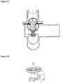
- sliding loose valve (3) which is not connected solidly to actuator with thermal element (4) starts to allow or obstruct the coolant fluid to flow through the by-pass output (B) and simultaneously the radiator valve (6) starts to obstruct or allow the coolant fluid to flow through the radiator output (R) with the movement created by the actuator with thermal element (4). Due to pressure difference applied on both sides of sliding loose valve (3), the sliding loose valve (3) leans against valve seat and prevent leakiness through the valve system while it is fully closed. Since slider valve is leaned against valve seat, the clearance between the sliding loose valve (3) and the seating surface of the valve on the body (2) is zeroed in
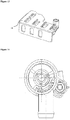
- thermal management module with loose slider valve comprise a body (2) which has two parts just about upper and lower case, a preferably paraffin based temperature sensitive actuator with thermal element (4), a spring (5) which forces the actuator with thermal element (4) to opposite direction, a radiator valve (6) which controls the flow through the radiator output (R) and a sliding loose valve (3)
- a sliding loosed valve (3), an actuator with thermal element (4) and a spring (5) is fitted inside a body (2).
- Upper part of the body (2) has a geometry which allows radiator output (R) and by-pass output connections (B) and lower part has a geometry which allows input (G) and actuator with thermal element (4) connections.
- connection elements (7) to provide a connection between the sliding loose valve (3) and the actuator with thermal element (4) which are in fact extensions of the radiator valve (6). These primary connection elements (7) transfer the movement of the actuator with thermal element (4) to the sliding loose valve (3) by contacting the sliding loose valve (3).
- the shaft of the actuator with thermal element (4) is surrounded by the wall thickness of the body (2) around that shaft which guides the shaft so that a movement only on the axis of the space (21) is provided for the actuator with thermal element (4).
- an actuator with thermal element (4) moves up and down bidirectionally on the axis of the space (21) inside of the body (2) so that the flow to different outputs are allowed or obstructed. This movement is also transferred to the sliding loose valve (3) by the primary connection element (7) in this way the flow of the radiator output (R) and by-pass output (B) is controlled.
- Actuator with thermal element (4) is filled with a compound which is temperature sensible and this compound expands or shrinks directly proportional to temperature. Thereby in case temperature increases, actuator with thermal element (4) starts to apply a downward force and push the sliding loose valve (3) and radiator valve (6) to move downward too. This movement also causes a downward movement on the spring (5) and by this movement spring (5) starts tensing and the radiator output (R) starts opening. Meantime by the downward movement of the sliding loose valve (3) by-pass output (B) starts closing. During this movement radiator output (R) is opened and by-pass output is closed simultaneously and a flow through radiator output (R) is provided and the flow through the by-pass output (B) is obstructed gradually.
- radiator output (R) is fully opened and the absolute amount of the coolant fluid is provided to flow through the radiator output (R).
- radiator output (R) is closed and by-pass output (B) is opened simultaneously by the upward moving radiator valve (6), sliding loose valve (3) and the actuator with thermal element (4).
- Upward moving radiator valve (6) starts to block radiator output (R) and upward moving sliding loose valve (3) starts to open by-pass output (B). This movement continues till the radiator output (R) is fully blocked by the radiator valve (6). When it is blocked fully, radiator output (R) is closed and by-pass output (B) is opened and the absolute amount of the coolant fluid is provided to flow through the by-pass output (B).
- Sliding loosed valve (3) is guided by the body (2). There is no accurate overlap between the surface of the sliding loose valve (3) and the surface of guiding body (2). There is some clearance. This clearance is removed by the pressure drop between two sides of the sliding loose valve (3) which is generated by the flow pressure of the coolant liquid and which forces the sliding loose valve (3) to lean against the seating surface of the body (3) by this pressure drop sealing is provided.
- Thermal management module with loose slider valve which is a component of the coolant circulation system of the internal combustion engines essentially comprises:
- movement is supplied by an electromechanical drive mechanism (9).
- the primary shaft (91) which is in fact a part of the electromechanical actuator (9) is guided by the guiding hole (101).
- Spindle drive mechanism (10) is driven by primary shaft (91).
- Primary shaft rotates to a direction by the guiding hole (101), this movement is transferred to the spindle drive mechanism (10).
- This rotational movement on the spindle drive mechanism is transformed to a linear movement by the secondary connection element (102) which is in form of a nut and driven by spindle drive (105).
- Primary connection element (7) is connected directly to the secondary connection element (102) by this means sliding loose valve (3) is driven. For one direction, sliding loose valve (3) starts to open the radiator output (R) and close the by-pass output (B).
- the force which is required to drive the sliding loose valve (3) on the axis of the space (21) is provided by an actuator with thermal element (4) which has a heating element (12).
- Thermal management module with loose slider valve which is a component of the coolant circulation system of the internal combustion engines essentially comprises:
- the force which is needed to drive the valves is provided by an actuator with thermal element (4) preferably including a heating element (12). It comprises an actuator with thermal element (4), preferably an electrical heating element (12) to heat the actuator with thermal element (4), a spring (5) which apply a force to the actuator with thermal element (4) to the closing direction when temperature decreases, a radiator valve (6) to control the flow through the radiator output (R) and a sliding loose valve (3) to control the flow through the by-pass output (B).
- Upper case of the body (2) has a suitable geometry for by-pass output (B) and radiator output (R) as well as lower case of the body (2) has for input (G) and actuator with thermal element (4).
- Primary connection element (7) transfers the movement of the actuator with thermal element (4) to the sliding loose valve (3).
- the actuator with thermal element (4) is forced to move to the opening direction by heating by the aid of the heating element (12) to allow the fluid to flow through desired outputs with desired flow rates.
- This movement causes a tension on the spring (5).
- radiator output (R) starts to open and by-pass output (B) starts to close.
- This movement continues till the actuator with thermal element (4) reaches its full open position. So radiator output (R) is fully opened and by-pass output (B) is fully closed thereby absolute amount of the coolant fluid is provided to flow through the radiator output (R).
- radiator output (R) is closed and by-pass output (B) is opened simultaneously by the moving radiator valve (6) sliding loose valve (3) and the actuator with thermal element (4).
- Moving radiator valve (6) starts to block radiator output (R) and moving sliding loose valve (3) starts to open by-pass output (B). This movement continues till the radiator output (R) is fully blocked by the radiator valve (6). When it is blocked fully, radiator output (R) is closed and by-pass output (B) is opened and the absolute amount of the coolant fluid is provided to flow through the by-pass output (B).
- Sliding loose valve (3) is guided by the seating element (11). There is no accurate overlap between the surface of the sliding loose valve (3) and the surface of seating element (11). There are some clearances in millimeters. This clearance is removed by the pressure drop between two sides of the sliding loose valve (3) which is generated by the flow pressure of the coolant liquid and by this pressure drop sealing is provided.
Landscapes
- Engineering & Computer Science (AREA)
- General Engineering & Computer Science (AREA)
- Mechanical Engineering (AREA)
- Chemical & Material Sciences (AREA)
- Combustion & Propulsion (AREA)
- Temperature-Responsive Valves (AREA)
Claims (11)
- Wärmemanagementmodul mit losem Schieberventil für Kühlkreisläufe der Verbrennungsmotoren, das im Wesentlichen mindestens einen Eingang (G) umfasst, der das Kühlmittel aus dem Motorblock überträgt, and gekennzeichnet durch,- Mindestens ein Körper (2), der Gehäuse für die Elemente des Wärmemanagementmoduls mit losem Schieberventil vorsieht und zwei Teile aufweist, die oben und unten anstehen und das Kühlmittel vom Eingang (G) übertragen- Mindestens ein Raum (21), der sich innerhalb des Körpers befindet und in dem Komponenten des Moduls installiert sind- Mindestens ein schiebendes loses Ventil (3) innerhalb des Raumes (21), das sich entlang der Achse des Raumes (21) bidirektional auf und ab bewegt und den Durchfluss der Kühlmittelflüssigkeit steuert- Mindestens ein Stellglied mit dem Wärmeelement (4) innerhalb des Raumes (21), das sich entsprechend der Temperaturänderung auf und ab auf der Achse des Raumes (21) bewegt und durch diese Änderung eine zum Antreiben eines Heizkörperventil (6) und ein schiebendes loses Ventils (3) zu erzeugende Kraft erzeugt und die Temperatur des Kühlmittels steuert- Mindestens eine Feder (5) innerhalb des Raumes (21), die eine Kraft auf das Stellglied mit dem Wärmeelement (4) in die entgegengesetzte Richtung der vom Stellglied erzeugten Kraft mit dem Wärmeelement (4) ausübt- Mindestens ein Heizkörperventil (6), das den Durchfluss des Kühlmittels durch die Heizkörperleistung (R) durch Öffnen und Schließen steuert und das mit dem Stellglied mit dem Wärmeelement (4) verbunden ist- Mindestens zwei primäre Verbindungselemente (7), die in der Tat eine Ausdehnung des Heizkörperventils (6) sind und die Bewegung des Stellglieds mit dem Wärmeelement (4) auf das lose Ventil (3) durch die Löcher übertragen, die primäre Verbindungselemente (7) am schiebenden losen Ventil (3) führen- Mindestens zwei Führungszähne (8), die in der Tat eine Dehnung des Körpers (2) in und entlang des Raumes (21) sind, der das schiebende lose Ventil (3) auf der Achse des Raumes (21) hält, indem er von beiden Kanten geführt wird.
- Wärmemanagementmodul mit losem Schieberventil (1) nach Anspruch 1, gekennzeichnet durch einen Körper (2), dessen oberer Teil mit der Heizkörperleistung (R) und der Bypassleistung (B) und dessen unterer Teil mit dem Eingang (G) und dem Stellglied mit dem Wärmeelement verbunden ist.
- Wärmemanagementmodul mit losem Schieberventil (1) nach Anspruch 1, gekennzeichnet durch ein Stellglied mit dem Wärmeelement (4), das eine wärmeempfindliche Verbindung im Inneren aufweist oder das durch ein wärmeempfindliches Element hergestellt ist.
- Wärmemanagementmodul mit losem Schieberventil (1) nach Anspruch 1, gekennzeichnet durch ein Stellglied mit dem Wärmeelement (4), das eine paraffinbasierte Verbindung im Inneren aufweist.
- Wärmemanagementmodul mit losem Schieberventil (1) nach Anspruch 1, gekennzeichnet durch ein Stellglied mit dem Wärmeelement (4), das sich temperaturabhängig ausdehnt und eine Kraft nach unten erzeugt und das Stellglied mit dem Wärmeelement (4) und das schiebende lose Ventil (3) durch diese Kraft nach unten antreibt und das durch eine Feder (5) im Falle eines durch Temperaturabfälle verursachten Schrumpfens nach oben zurückgedrückt wird
- Wärmemanagementmodul mit losem Schieberventil (1) nach Anspruch 1, gekennzeichnet durch ein schiebendes loses Ventil (3), das durch den Druckabfall, der durch die Strömungen der Kühlmittel auf beiden Seiten erzeugt wird, eine Abdichtung bewirkt.
- Wärmemanagementmodul mit losem Schieberventil (1) nach Anspruch 1, gekennzeichnet durch einen Körper (2), der eine Wanddicke um die Welle des Stellglieds aufweist, mit dem Wärmeelement (4), das diese Welle umschließt, um die Welle zu führen, um eine Bewegung nur auf der Achse des Raumes (21) für das Stellglied mit dem Wärmeelement (4) vorzusehen.
- Wärmemanagementmodul mit losem Schieberventil für Kühlkreisläufe der Verbrennungsmotoren, das im Wesentlichen mindestens einen Eingang (G) umfasst, der das Kühlmittel aus dem Motorblock überträgt und gekennzeichnet durch,- Mindestens ein Körper (2), der Gehäuse für die Elemente des Wärmemanagementmoduls mit losem Schieberventil vorsieht und zwei Teile aufweist, die oben und unten anstehen und das Kühlmittel vom Eingang (G) übertragen- Mindestens ein Raum (21), der sich innerhalb des Körpers befindet und in dem Komponenten des Moduls installiert sind- Mindestens ein elektromechanisches Stellglied (9)- Mindestens ein schiebendes loses Ventil (3) innerhalb des Raumes (21), das sich entlang der Achse des Raumes (21) bidirektional auf und ab bewegt und den Durchfluss der Kühlmittelflüssigkeit steuert.- Mindestens eine Primärwelle (91), die tatsächlich ein Teil des elektromechanischen Stellglieds (9) ist und eine Drehbewegung ausführt- Mindestens eine Kupplung (92), die eine Bohrung aufweist, die von der Primärwelle (91) verfahrbar ist und die eine Bewegung ohne Axialschlag vorzusehen kann- Mindestens ein Spindelantriebsmechanismus (10), der die Drehbewegung von der Primärwelle (91) auf ein schiebendes loses Schieberventil (3) überträgt- Mindestens ein Spindelantrieb (105), der sich entlang des Raums (21) innerhalb des Körpers (2) erstreckt und eine Führungsbohrung (101) auf der Seite der Primärwelle (91) aufweist und sich gleichzeitig mit der Primärwelle (91) dreht- Mindestens ein primäres Verbindungselement (7), das tatsächlich eine Ausdehnung des schiebenden losen Ventils (3) ist,- Mindestens ein sekundäres Verbindungselement (102), das von der im Körper (2) befindlichen Seite mit dem Spindelantrieb (105) verbunden ist und mit einem Vorsprung in eine Führungsbohrung am primären Verbindungselement (7) eingesetzt ist und das primäre Verbindungselement (7) gemäß der Drehrichtung des Spindelantriebs (105) in Öffnungs- oder Schließrichtung antreibt- Mindestens ein Sitzelement (11), das mit dem Körper (2) verbunden ist und parallel zum schiebenden losen Ventil (3) verläuft und an dem das schiebende lose Ventil (3) eine Schiebebewegung ausführt- Mindestens zwei Neigungspunkte (103), die mit dem Spindelantrieb (105) von seinem Berührungspunkt aus mit dem primären Verbindungselement (7), dem sekundären Verbindungselement (102) und dem Körper (2) verbunden sind und so angeordnet sind, dass sie die Bewegung des Spindelantriebsmechanismus (10) zwischen dem gewünschten Bereich und dem Bereich begrenzen und- Mindestens ein Dichtelement (104), das mit der Oberfläche des Spindelantriebsmechanismus (10) verbunden ist, um die Reibungseinflüsse auf die Gelenkflächen zu reduzieren
- Wärmemanagementmodul mit losem Schieberventil (1) nach Anspruch 8, gekennzeichnet durch eine Primärwelle (91), die tatsächlich ein Teil des elektromechanischen Stellglieds (9) ist und eine Drehbewegung ausführt.
- Wärmemanagementmodul mit losem Schieberventil (1) nach Anspruch 8, gekennzeichnet durch ein sekundäres Verbindungselement (102), das tatsächlich eine Mutter ist.
- Wärmemanagementmodul mit losem Schieberventil für Kühlkreisläufe der Verbrennungsmotoren, das im Wesentlichen mindestens einen Eingang (G) umfasst, der das Kühlmittel aus dem Motorblock überträgt, gekennzeichnet durch,- Mindestens ein Körper (2), der Gehäuse für die Elemente des Wärmemanagementmoduls mit losem Schieberventil vorsieht und zwei Teile aufweist, die oben und unten anstehen und das Kühlmittel vom Eingang (G) übertragen- Mindestens ein Raum (21), der sich innerhalb des Körpers befindet und in dem Komponenten des Moduls installiert sind.- Mindestens schiebendes loses Ventil (3) innerhalb des Raumes (21), das sich bidirektional bewegt und den Durchfluss der Kühlmittelflüssigkeit steuert.- Mindestens ein Stellglied mit dem Wärmeelement (4), das mit einem Heizelement (12) in Kontakt steht und sich entsprechend der Temperaturänderung auf und ab auf der Achse des Raumes (21) bewegt und durch diese Änderung eine zum Antreiben des losen Ventils (3) zu erzeugende Kraft erzeugt und die Temperatur des Kühlmittels steuert.- Mindestens eine Feder (5), die eine Kraft auf das Stellglied mit dem Wärmeelement (4) in die entgegengesetzte Richtung der vom Stellglied mit dem Wärmeelement (4) bei Temperaturabsenkung erzeugten Kraft ausübt- Mindestens ein Heizkörperventil (6), das den Durchfluss des Kühlmittels durch die Heizkörperleistung (R) steuert und das mit dem Stellglied mit dem Wärmeelement (4) verbunden ist- Mindestens ein primäres Verbindungselement (7), das tatsächlich eine Ausdehnung des Heizkörperventils (6) ist und die Bewegung des Stellglieds mit dem Wärmeelement (4) auf das schiebende lose Ventil (3) überträgt- Mindestens ein Sitzelement (11), das mit dem Körper (2) verbunden ist und parallel zum schiebenden losen Ventil (3) verläuft und an dem das schiebende lose Ventil (3) eine Schiebebewegung ausführt.
Applications Claiming Priority (1)
| Application Number | Priority Date | Filing Date | Title |
|---|---|---|---|
| PCT/TR2016/050060 WO2017155483A1 (en) | 2016-03-07 | 2016-03-07 | A thermal management module with loose slider valve |
Publications (2)
| Publication Number | Publication Date |
|---|---|
| EP3426954A1 EP3426954A1 (de) | 2019-01-16 |
| EP3426954B1 true EP3426954B1 (de) | 2019-12-11 |
Family
ID=56024366
Family Applications (1)
| Application Number | Title | Priority Date | Filing Date |
|---|---|---|---|
| EP16723845.0A Active EP3426954B1 (de) | 2016-03-07 | 2016-03-07 | Wärmeverwaltungsmodul mit losem sperrschieber |
Country Status (3)
| Country | Link |
|---|---|
| EP (1) | EP3426954B1 (de) |
| CN (1) | CN108779863B (de) |
| WO (1) | WO2017155483A1 (de) |
Families Citing this family (1)
| Publication number | Priority date | Publication date | Assignee | Title |
|---|---|---|---|---|
| FR3074927B1 (fr) * | 2017-12-13 | 2020-10-23 | Novares France | Vanne thermostatique |
Family Cites Families (7)
| Publication number | Priority date | Publication date | Assignee | Title |
|---|---|---|---|---|
| US4875437A (en) * | 1987-12-03 | 1989-10-24 | Procedes Vernet | Apparatus for controlling the flow of cooling fluid in an engine |
| US5005605A (en) * | 1989-07-10 | 1991-04-09 | Keystone International Holdings Corp. | Conditioning valve |
| JP2005133689A (ja) * | 2003-10-31 | 2005-05-26 | Toyota Motor Corp | 内燃機関昇温装置 |
| FR2868811B1 (fr) * | 2004-04-07 | 2006-07-14 | Mark Iv Systemes Moteurs Sa | Dispositif de regulation du type boitier de sortie d'eau |
| SE532137C2 (sv) * | 2006-10-04 | 2009-10-27 | Tour & Andersson Ab | Ventil med reglerfunktion |
| US7721973B2 (en) * | 2007-04-03 | 2010-05-25 | Dana Canada Corporation | Valve |
| DE102008056245A1 (de) | 2008-11-06 | 2010-05-20 | Itw Automotive Products Gmbh | Thermostatventil |
-
2016
- 2016-03-07 EP EP16723845.0A patent/EP3426954B1/de active Active
- 2016-03-07 CN CN201680083162.3A patent/CN108779863B/zh not_active Expired - Fee Related
- 2016-03-07 WO PCT/TR2016/050060 patent/WO2017155483A1/en not_active Ceased
Non-Patent Citations (1)
| Title |
|---|
| None * |
Also Published As
| Publication number | Publication date |
|---|---|
| CN108779863A (zh) | 2018-11-09 |
| CN108779863B (zh) | 2020-10-30 |
| WO2017155483A1 (en) | 2017-09-14 |
| EP3426954A1 (de) | 2019-01-16 |
Similar Documents
| Publication | Publication Date | Title |
|---|---|---|
| JP5919031B2 (ja) | 冷却水制御バルブ装置 | |
| EP2864608B1 (de) | Kühlsystem für kraftfahrzeugmotor und verfahren | |
| US9441744B2 (en) | Valve apparatus | |
| EP2864607B1 (de) | Flüssigkeitsmengenregler | |
| CN210461271U (zh) | 阀 | |
| EP2057520B1 (de) | System und verfahren zum regeln der wärmeübertragung an einem fluid durch regeln der strömung des fluids | |
| US8973537B2 (en) | Engine having thermostat and system thereof | |
| CA2651289C (en) | Valve | |
| WO2015091691A1 (en) | A valve and a method of controlling a valve in a fluid conduit | |
| US10876463B2 (en) | Apparatus and method for controlling flow rate of engine coolant by use of a thermostat | |
| KR20150136590A (ko) | 유압-구동 서모스탯 | |
| CN107110166A (zh) | 具有由形状记忆元件操纵的滑块的冷却剂泵 | |
| DE102011077901A1 (de) | Thermostatventil | |
| CN115023680A (zh) | 用于控制流体流动的装置 | |
| CN114876626A (zh) | 用于机动车辆的流体回路 | |
| CA2431717C (en) | Proportional valve with linear actuator | |
| EP3426954A1 (de) | Wärmeverwaltungsmodul mit losem sperrschieber | |
| CN110036185B (zh) | 用于内燃机的恒温阀 | |
| CN114251508A (zh) | 调节阀位置检测 | |
| CN112041547A (zh) | 通过阀平衡使阀结构和壳体之间摩擦力最小的恒温器组件 | |
| EP3039321B1 (de) | Bypassventil | |
| US12007796B2 (en) | Thermostatic valve | |
| EP2689142A1 (de) | Ventil | |
| KR101047752B1 (ko) | 유체의 열 교환용 밸브 | |
| JP2012026341A (ja) | 流体制御弁 |
Legal Events
| Date | Code | Title | Description |
|---|---|---|---|
| STAA | Information on the status of an ep patent application or granted ep patent |
Free format text: STATUS: THE INTERNATIONAL PUBLICATION HAS BEEN MADE |
|
| PUAI | Public reference made under article 153(3) epc to a published international application that has entered the european phase |
Free format text: ORIGINAL CODE: 0009012 |
|
| STAA | Information on the status of an ep patent application or granted ep patent |
Free format text: STATUS: REQUEST FOR EXAMINATION WAS MADE |
|
| 17P | Request for examination filed |
Effective date: 20180629 |
|
| AK | Designated contracting states |
Kind code of ref document: A1 Designated state(s): AL AT BE BG CH CY CZ DE DK EE ES FI FR GB GR HR HU IE IS IT LI LT LU LV MC MK MT NL NO PL PT RO RS SE SI SK SM TR |
|
| AX | Request for extension of the european patent |
Extension state: BA ME |
|
| STAA | Information on the status of an ep patent application or granted ep patent |
Free format text: STATUS: EXAMINATION IS IN PROGRESS |
|
| 17Q | First examination report despatched |
Effective date: 20190320 |
|
| DAV | Request for validation of the european patent (deleted) | ||
| DAX | Request for extension of the european patent (deleted) | ||
| GRAP | Despatch of communication of intention to grant a patent |
Free format text: ORIGINAL CODE: EPIDOSNIGR1 |
|
| STAA | Information on the status of an ep patent application or granted ep patent |
Free format text: STATUS: GRANT OF PATENT IS INTENDED |
|
| INTG | Intention to grant announced |
Effective date: 20190918 |
|
| GRAS | Grant fee paid |
Free format text: ORIGINAL CODE: EPIDOSNIGR3 |
|
| GRAA | (expected) grant |
Free format text: ORIGINAL CODE: 0009210 |
|
| STAA | Information on the status of an ep patent application or granted ep patent |
Free format text: STATUS: THE PATENT HAS BEEN GRANTED |
|
| AK | Designated contracting states |
Kind code of ref document: B1 Designated state(s): AL AT BE BG CH CY CZ DE DK EE ES FI FR GB GR HR HU IE IS IT LI LT LU LV MC MK MT NL NO PL PT RO RS SE SI SK SM TR |
|
| REG | Reference to a national code |
Ref country code: GB Ref legal event code: FG4D |
|
| REG | Reference to a national code |
Ref country code: CH Ref legal event code: EP |
|
| REG | Reference to a national code |
Ref country code: AT Ref legal event code: REF Ref document number: 1212525 Country of ref document: AT Kind code of ref document: T Effective date: 20191215 |
|
| REG | Reference to a national code |
Ref country code: DE Ref legal event code: R096 Ref document number: 602016025983 Country of ref document: DE |
|
| REG | Reference to a national code |
Ref country code: IE Ref legal event code: FG4D |
|
| REG | Reference to a national code |
Ref country code: SE Ref legal event code: TRGR |
|
| REG | Reference to a national code |
Ref country code: NL Ref legal event code: MP Effective date: 20191211 |
|
| REG | Reference to a national code |
Ref country code: LT Ref legal event code: MG4D |
|
| PG25 | Lapsed in a contracting state [announced via postgrant information from national office to epo] |
Ref country code: NO Free format text: LAPSE BECAUSE OF FAILURE TO SUBMIT A TRANSLATION OF THE DESCRIPTION OR TO PAY THE FEE WITHIN THE PRESCRIBED TIME-LIMIT Effective date: 20200311 Ref country code: GR Free format text: LAPSE BECAUSE OF FAILURE TO SUBMIT A TRANSLATION OF THE DESCRIPTION OR TO PAY THE FEE WITHIN THE PRESCRIBED TIME-LIMIT Effective date: 20200312 Ref country code: LT Free format text: LAPSE BECAUSE OF FAILURE TO SUBMIT A TRANSLATION OF THE DESCRIPTION OR TO PAY THE FEE WITHIN THE PRESCRIBED TIME-LIMIT Effective date: 20191211 Ref country code: LV Free format text: LAPSE BECAUSE OF FAILURE TO SUBMIT A TRANSLATION OF THE DESCRIPTION OR TO PAY THE FEE WITHIN THE PRESCRIBED TIME-LIMIT Effective date: 20191211 Ref country code: BG Free format text: LAPSE BECAUSE OF FAILURE TO SUBMIT A TRANSLATION OF THE DESCRIPTION OR TO PAY THE FEE WITHIN THE PRESCRIBED TIME-LIMIT Effective date: 20200311 Ref country code: FI Free format text: LAPSE BECAUSE OF FAILURE TO SUBMIT A TRANSLATION OF THE DESCRIPTION OR TO PAY THE FEE WITHIN THE PRESCRIBED TIME-LIMIT Effective date: 20191211 |
|
| PGFP | Annual fee paid to national office [announced via postgrant information from national office to epo] |
Ref country code: DE Payment date: 20200211 Year of fee payment: 5 Ref country code: GB Payment date: 20200330 Year of fee payment: 5 Ref country code: SE Payment date: 20200330 Year of fee payment: 5 |
|
| PG25 | Lapsed in a contracting state [announced via postgrant information from national office to epo] |
Ref country code: RS Free format text: LAPSE BECAUSE OF FAILURE TO SUBMIT A TRANSLATION OF THE DESCRIPTION OR TO PAY THE FEE WITHIN THE PRESCRIBED TIME-LIMIT Effective date: 20191211 Ref country code: HR Free format text: LAPSE BECAUSE OF FAILURE TO SUBMIT A TRANSLATION OF THE DESCRIPTION OR TO PAY THE FEE WITHIN THE PRESCRIBED TIME-LIMIT Effective date: 20191211 |
|
| PG25 | Lapsed in a contracting state [announced via postgrant information from national office to epo] |
Ref country code: AL Free format text: LAPSE BECAUSE OF FAILURE TO SUBMIT A TRANSLATION OF THE DESCRIPTION OR TO PAY THE FEE WITHIN THE PRESCRIBED TIME-LIMIT Effective date: 20191211 |
|
| PGFP | Annual fee paid to national office [announced via postgrant information from national office to epo] |
Ref country code: FR Payment date: 20200324 Year of fee payment: 5 Ref country code: TR Payment date: 20200213 Year of fee payment: 5 |
|
| PG25 | Lapsed in a contracting state [announced via postgrant information from national office to epo] |
Ref country code: ES Free format text: LAPSE BECAUSE OF FAILURE TO SUBMIT A TRANSLATION OF THE DESCRIPTION OR TO PAY THE FEE WITHIN THE PRESCRIBED TIME-LIMIT Effective date: 20191211 Ref country code: EE Free format text: LAPSE BECAUSE OF FAILURE TO SUBMIT A TRANSLATION OF THE DESCRIPTION OR TO PAY THE FEE WITHIN THE PRESCRIBED TIME-LIMIT Effective date: 20191211 Ref country code: PT Free format text: LAPSE BECAUSE OF FAILURE TO SUBMIT A TRANSLATION OF THE DESCRIPTION OR TO PAY THE FEE WITHIN THE PRESCRIBED TIME-LIMIT Effective date: 20200506 Ref country code: CZ Free format text: LAPSE BECAUSE OF FAILURE TO SUBMIT A TRANSLATION OF THE DESCRIPTION OR TO PAY THE FEE WITHIN THE PRESCRIBED TIME-LIMIT Effective date: 20191211 Ref country code: NL Free format text: LAPSE BECAUSE OF FAILURE TO SUBMIT A TRANSLATION OF THE DESCRIPTION OR TO PAY THE FEE WITHIN THE PRESCRIBED TIME-LIMIT Effective date: 20191211 Ref country code: RO Free format text: LAPSE BECAUSE OF FAILURE TO SUBMIT A TRANSLATION OF THE DESCRIPTION OR TO PAY THE FEE WITHIN THE PRESCRIBED TIME-LIMIT Effective date: 20191211 |
|
| PG25 | Lapsed in a contracting state [announced via postgrant information from national office to epo] |
Ref country code: IS Free format text: LAPSE BECAUSE OF FAILURE TO SUBMIT A TRANSLATION OF THE DESCRIPTION OR TO PAY THE FEE WITHIN THE PRESCRIBED TIME-LIMIT Effective date: 20200411 Ref country code: SK Free format text: LAPSE BECAUSE OF FAILURE TO SUBMIT A TRANSLATION OF THE DESCRIPTION OR TO PAY THE FEE WITHIN THE PRESCRIBED TIME-LIMIT Effective date: 20191211 Ref country code: SM Free format text: LAPSE BECAUSE OF FAILURE TO SUBMIT A TRANSLATION OF THE DESCRIPTION OR TO PAY THE FEE WITHIN THE PRESCRIBED TIME-LIMIT Effective date: 20191211 |
|
| REG | Reference to a national code |
Ref country code: DE Ref legal event code: R097 Ref document number: 602016025983 Country of ref document: DE |
|
| REG | Reference to a national code |
Ref country code: AT Ref legal event code: MK05 Ref document number: 1212525 Country of ref document: AT Kind code of ref document: T Effective date: 20191211 |
|
| PLBE | No opposition filed within time limit |
Free format text: ORIGINAL CODE: 0009261 |
|
| STAA | Information on the status of an ep patent application or granted ep patent |
Free format text: STATUS: NO OPPOSITION FILED WITHIN TIME LIMIT |
|
| PG25 | Lapsed in a contracting state [announced via postgrant information from national office to epo] |
Ref country code: DK Free format text: LAPSE BECAUSE OF FAILURE TO SUBMIT A TRANSLATION OF THE DESCRIPTION OR TO PAY THE FEE WITHIN THE PRESCRIBED TIME-LIMIT Effective date: 20191211 Ref country code: MC Free format text: LAPSE BECAUSE OF FAILURE TO SUBMIT A TRANSLATION OF THE DESCRIPTION OR TO PAY THE FEE WITHIN THE PRESCRIBED TIME-LIMIT Effective date: 20191211 |
|
| REG | Reference to a national code |
Ref country code: CH Ref legal event code: PL |
|
| 26N | No opposition filed |
Effective date: 20200914 |
|
| PG25 | Lapsed in a contracting state [announced via postgrant information from national office to epo] |
Ref country code: SI Free format text: LAPSE BECAUSE OF FAILURE TO SUBMIT A TRANSLATION OF THE DESCRIPTION OR TO PAY THE FEE WITHIN THE PRESCRIBED TIME-LIMIT Effective date: 20191211 Ref country code: AT Free format text: LAPSE BECAUSE OF FAILURE TO SUBMIT A TRANSLATION OF THE DESCRIPTION OR TO PAY THE FEE WITHIN THE PRESCRIBED TIME-LIMIT Effective date: 20191211 |
|
| REG | Reference to a national code |
Ref country code: BE Ref legal event code: MM Effective date: 20200331 |
|
| PG25 | Lapsed in a contracting state [announced via postgrant information from national office to epo] |
Ref country code: LU Free format text: LAPSE BECAUSE OF NON-PAYMENT OF DUE FEES Effective date: 20200307 |
|
| PG25 | Lapsed in a contracting state [announced via postgrant information from national office to epo] |
Ref country code: IT Free format text: LAPSE BECAUSE OF FAILURE TO SUBMIT A TRANSLATION OF THE DESCRIPTION OR TO PAY THE FEE WITHIN THE PRESCRIBED TIME-LIMIT Effective date: 20191211 Ref country code: LI Free format text: LAPSE BECAUSE OF NON-PAYMENT OF DUE FEES Effective date: 20200331 Ref country code: IE Free format text: LAPSE BECAUSE OF NON-PAYMENT OF DUE FEES Effective date: 20200307 Ref country code: CH Free format text: LAPSE BECAUSE OF NON-PAYMENT OF DUE FEES Effective date: 20200331 |
|
| PG25 | Lapsed in a contracting state [announced via postgrant information from national office to epo] |
Ref country code: BE Free format text: LAPSE BECAUSE OF NON-PAYMENT OF DUE FEES Effective date: 20200331 Ref country code: PL Free format text: LAPSE BECAUSE OF FAILURE TO SUBMIT A TRANSLATION OF THE DESCRIPTION OR TO PAY THE FEE WITHIN THE PRESCRIBED TIME-LIMIT Effective date: 20191211 |
|
| REG | Reference to a national code |
Ref country code: DE Ref legal event code: R119 Ref document number: 602016025983 Country of ref document: DE |
|
| GBPC | Gb: european patent ceased through non-payment of renewal fee |
Effective date: 20210307 |
|
| PG25 | Lapsed in a contracting state [announced via postgrant information from national office to epo] |
Ref country code: DE Free format text: LAPSE BECAUSE OF NON-PAYMENT OF DUE FEES Effective date: 20211001 Ref country code: SE Free format text: LAPSE BECAUSE OF NON-PAYMENT OF DUE FEES Effective date: 20210308 Ref country code: FR Free format text: LAPSE BECAUSE OF NON-PAYMENT OF DUE FEES Effective date: 20210331 Ref country code: GB Free format text: LAPSE BECAUSE OF NON-PAYMENT OF DUE FEES Effective date: 20210307 |
|
| PG25 | Lapsed in a contracting state [announced via postgrant information from national office to epo] |
Ref country code: MT Free format text: LAPSE BECAUSE OF FAILURE TO SUBMIT A TRANSLATION OF THE DESCRIPTION OR TO PAY THE FEE WITHIN THE PRESCRIBED TIME-LIMIT Effective date: 20191211 Ref country code: CY Free format text: LAPSE BECAUSE OF FAILURE TO SUBMIT A TRANSLATION OF THE DESCRIPTION OR TO PAY THE FEE WITHIN THE PRESCRIBED TIME-LIMIT Effective date: 20191211 |
|
| PG25 | Lapsed in a contracting state [announced via postgrant information from national office to epo] |
Ref country code: MK Free format text: LAPSE BECAUSE OF FAILURE TO SUBMIT A TRANSLATION OF THE DESCRIPTION OR TO PAY THE FEE WITHIN THE PRESCRIBED TIME-LIMIT Effective date: 20191211 |