EP3427367B1 - Linear-motor stator with integral line reactor - Google Patents
Linear-motor stator with integral line reactor Download PDFInfo
- Publication number
- EP3427367B1 EP3427367B1 EP17763733.7A EP17763733A EP3427367B1 EP 3427367 B1 EP3427367 B1 EP 3427367B1 EP 17763733 A EP17763733 A EP 17763733A EP 3427367 B1 EP3427367 B1 EP 3427367B1
- Authority
- EP
- European Patent Office
- Prior art keywords
- stator
- linear
- core portion
- coils
- reactor
- Prior art date
- Legal status (The legal status is an assumption and is not a legal conclusion. Google has not performed a legal analysis and makes no representation as to the accuracy of the status listed.)
- Active
Links
Images
Classifications
-
- H—ELECTRICITY
- H02—GENERATION; CONVERSION OR DISTRIBUTION OF ELECTRIC POWER
- H02K—DYNAMO-ELECTRIC MACHINES
- H02K41/00—Propulsion systems in which a rigid body is moved along a path due to dynamo-electric interaction between the body and a magnetic field travelling along the path
- H02K41/02—Linear motors; Sectional motors
-
- H—ELECTRICITY
- H02—GENERATION; CONVERSION OR DISTRIBUTION OF ELECTRIC POWER
- H02K—DYNAMO-ELECTRIC MACHINES
- H02K1/00—Details of the magnetic circuit
- H02K1/06—Details of the magnetic circuit characterised by the shape, form or construction
- H02K1/12—Stationary parts of the magnetic circuit
- H02K1/16—Stator cores with slots for windings
-
- H—ELECTRICITY
- H02—GENERATION; CONVERSION OR DISTRIBUTION OF ELECTRIC POWER
- H02K—DYNAMO-ELECTRIC MACHINES
- H02K1/00—Details of the magnetic circuit
- H02K1/06—Details of the magnetic circuit characterised by the shape, form or construction
- H02K1/12—Stationary parts of the magnetic circuit
- H02K1/17—Stator cores with permanent magnets
-
- H—ELECTRICITY
- H02—GENERATION; CONVERSION OR DISTRIBUTION OF ELECTRIC POWER
- H02K—DYNAMO-ELECTRIC MACHINES
- H02K11/00—Structural association of dynamo-electric machines with electric components or with devices for shielding, monitoring or protection
- H02K11/0094—Structural association with other electrical or electronic devices
-
- H—ELECTRICITY
- H02—GENERATION; CONVERSION OR DISTRIBUTION OF ELECTRIC POWER
- H02K—DYNAMO-ELECTRIC MACHINES
- H02K17/00—Asynchronous induction motors; Asynchronous induction generators
- H02K17/02—Asynchronous induction motors
- H02K17/12—Asynchronous induction motors for multi-phase current
-
- H—ELECTRICITY
- H02—GENERATION; CONVERSION OR DISTRIBUTION OF ELECTRIC POWER
- H02K—DYNAMO-ELECTRIC MACHINES
- H02K17/00—Asynchronous induction motors; Asynchronous induction generators
- H02K17/02—Asynchronous induction motors
- H02K17/30—Structural association of asynchronous induction motors with auxiliary electric devices influencing the characteristics of the motor or controlling the motor, e.g. with impedances or switches
-
- H—ELECTRICITY
- H02—GENERATION; CONVERSION OR DISTRIBUTION OF ELECTRIC POWER
- H02K—DYNAMO-ELECTRIC MACHINES
- H02K19/00—Synchronous motors or generators
- H02K19/02—Synchronous motors
- H02K19/10—Synchronous motors for multi-phase current
-
- H—ELECTRICITY
- H02—GENERATION; CONVERSION OR DISTRIBUTION OF ELECTRIC POWER
- H02K—DYNAMO-ELECTRIC MACHINES
- H02K3/00—Details of windings
- H02K3/46—Fastening of windings on the stator or rotor structure
- H02K3/48—Fastening of windings on the stator or rotor structure in slots
-
- H—ELECTRICITY
- H02—GENERATION; CONVERSION OR DISTRIBUTION OF ELECTRIC POWER
- H02K—DYNAMO-ELECTRIC MACHINES
- H02K41/00—Propulsion systems in which a rigid body is moved along a path due to dynamo-electric interaction between the body and a magnetic field travelling along the path
- H02K41/02—Linear motors; Sectional motors
- H02K41/025—Asynchronous motors
-
- H—ELECTRICITY
- H02—GENERATION; CONVERSION OR DISTRIBUTION OF ELECTRIC POWER
- H02K—DYNAMO-ELECTRIC MACHINES
- H02K41/00—Propulsion systems in which a rigid body is moved along a path due to dynamo-electric interaction between the body and a magnetic field travelling along the path
- H02K41/02—Linear motors; Sectional motors
- H02K41/03—Synchronous motors; Motors moving step by step; Reluctance motors
- H02K41/031—Synchronous motors; Motors moving step by step; Reluctance motors of the permanent magnet type
Definitions
- the invention relates generally to polyphase linear motors and more particularly to line reactors unitarily housed with linear-motor stators.
- Linear induction motors and other linear motors are often configured as polyphase motors, usually with three phases. Because of magnetic end effects and winding layouts, the inductances of the stator windings typically differ from phase to phase. The stator phases should be excited by currents nearly equal in magnitude so that an optimal traveling magnetic flux wave is generated.
- the current imbalance in stators resulting from unequal phase inductances is solved in two main ways. One solution is to drive the stator coils with a current-regulated amplifier, but current-regulated drives are expensive. Another way stator inductances are balanced is with inductive reactors.
- Inductor coils in the reactors are connected in series with the stator windings to balance the net inductances of the phases so that the stator can be driven by a more common variable-frequency drive (VFD).
- VFD variable-frequency drive
- US 2005/062356 A1 discloses an electric AC machine with a primary section and a secondary section.
- DE 44 23 783 A1 discloses a travelling-field inductor connected to a supply grid via a frequency converter comprising (a) capacitors connected to the inductor coils in such a way that they form respectively the capacitance and inductance of a parallel resonance circuit; (b) further inductors connected in series to this parallel resonance circuit form jointly with the capacitors a series resonance circuit.
- the stator includes a stator core portion having a first end and an opposite second end defining the length of the stator core portion and an outer face having a plurality of pole faces separated by a plurality of stator coil slots opening onto the outer face between the first and second ends.
- a plurality of sets of stator coils reside in the stator coil slots and are connected to form polyphase stator windings propagating a magnetic flux wave along the length of the stator portion through the pole faces.
- the reactor includes a reactor core portion abutting the stator core portion and having an outer face with a plurality of inductor coil slots opening onto the outer face.
- a plurality of inductor coils reside in the inductor coil slots. Each of the inductor coils is connected electrically in series with one or another of the sets of stator coils.
- a linear-motor system comprises a housing, a stator having three stator windings housed in the housing, a reactor having inductors housed in the housing adjacent to the stator, and a three-phase variable-frequency drive.
- the inductors are electrically connected between the three-phase variable-frequency drive and one or more of the three stator windings to balance the currents in the three stator windings.
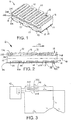
- FIGS. 1 and 2 A stator assembly embodying features of the invention is shown in FIGS. 1 and 2 for a linear motor, such as a linear induction motor or a linear synchronous motor.
- the stator assembly 10 comprises a core 12 that extends in length from a first end 14 to a second end 15.
- the core extends in thickness from an upper obverse outer face 16 to a lower reverse outer face 17.
- Slots 18 open onto the upper outer face 16 between the first and second ends 14, 15 and divide the upper outer face into pole faces 20 between consecutive slots.
- Stator coils 22 reside in the stator slots 18.
- the stator coils 22 are arranged in three layers: a bottom layer 24A, a middle layer 24B, and a top layer 24C.
- the stator coils 22 are arranged in three sets. The coils in each set are connected electrically in series to form one winding of a three-phase stator. For example, all the stator coils 22 in the bottom layer 24A could be wired in series to form the U-phase winding. The coils 22 in the middle layer 24B could be wired in series to form the V-phase winding. And the coils 22 in the top layer 24C could be wired in series to form the W-phase winding.
- the stator propagates a magnetic flux wave through the pole faces 20 in its upper outer face 18 in a propagation direction 26 along the length of the stator.
- Pairs of slots 28, 28' open onto the bottom outer face 17 of the core 12 to receive inductor coils 30A-C-three, in this example.
- a core piece 32 between each pair of inductor coil slots 28, 28' extends through the center of each inductor coil and forms a high permeability core for the coil.
- a steel plate 34 separated from the inductors' core pieces 32 and the bottom outer face 17 of the core 12 by a gap 36 serves as a magnetic shunt completing the inductors' magnetic circuits.
- the plate 34 can also serve as a mounting plate for the stator assembly 10.
- the inductor coils 30A-C can compensate for differences in the reactances of the stator coils.
- the induction coils are equivalent to line reactors.
- the inductor coils 30A-C and the stator coils 22 share the same core 12.
- the core 12 is thicker between the top and bottom faces 16, 17 than if the stator did not include the integral inductor coils 30A-C.
- the thicker core 12 helps decouple the stator flux from the inductor flux. So the core 12 is separated into a stator core portion 38 and a reactor core portion 39 by an imaginary plane 40 between the top and bottom faces 16, 17.
- the core 12 is constructed of transformer-steel laminations to reduce eddy currents, but could be a solid piece of metal. Appropriate sizing of the pole faces 20 and the depths of the slots 18, 28, 28' can result in the use of the same coil forms for both the stator coils 22 and the inductor coils 30A-C of the reactor.
- FIG. 3 The electrical wiring of the stator portion of a linear-motor system with the reactor inductors connected between the stator windings and a VFD is shown schematically in FIG. 3 .
- the three-phase output lines U, V, W of the VFD 42 are connected to the three stator windings, whose inductances are L u , L v , and L w . In general the three inductances will not be equal.
- a line reactor 44 composed of the inductor coils 30A-C is used. In this example, L U ⁇ L V ⁇ L W .
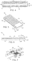
- FIG. 4 shows another version of the core.
- the core 46 comprises, rather than a monolithic core as in FIGS. 1 and 2 , two separate core pieces: a stator core portion 48 and a reactor core portion 49.
- the two portions 48, 49 are shown to have the same length and are encapsulated together to form an integral structure.
- the two separate pieces 48, 49 are separated back to back by a small gap 50 that helps magnetically isolate the flux return paths 52 of the stator coils 22 from the flux return paths 53 of the inductor coils 30.
- stator-assembly 54 in FIGS. 5 and 6 is configured with a stator core portion 56 abutting a reactor core portion 58 at an end 60 of the stator core portion.
- a single solid core or laminated core profile could be used to form a stator 62 integral with a reactor 64.
- the reactor 64 in FIG. 6 has three inductor coils 66A-C and three pole faces 68 facing upward in the same direction as stator pole faces 70.
- a magnetic-shunt plate 74 facing the reactor pole faces 68 completes the inductors' magnetic circuits.
- FIG. 7 shows an exemplary application for a linear-motor stator assembly as in any of FIGS. 1-6 .
- a stator assembly with integral reactors resides in a housing 78 beneath an array of electrically conductive or magnetic rollers 80 arranged in parallel across a small gap from the stator pole faces.
- the stator's magnetic flux wave induces currents in the rollers 80 that create magnetic fields that interact with the stator's magnetic flux wave and cause the rollers to rotate.
- the electrically conductive rollers 80 serve as rotors that form linear induction motors with the stator.
- the stator's magnetic flux wave interacts with the magnetic fields of the permanent magnets and causes the rollers to rotate.
- the magnetic rollers 80 serve as rotors that form linear synchronous motors with the stator. Boxes 82 transfer across the rotating rollers 80 from an infeed conveyor belt 84 to a discharge conveyor belt 86.
- the system could be a polyphase system of more than three phases.
- the use of the terms "integral" or "unitary” with respect to the stator and the reactor means that they are joined and enclosed together in a single housing.
- the unitary stator and reactor can share a common monolithic (solid or laminated) core or can have separate cores. One is not external to the other's housing.
Landscapes
- Engineering & Computer Science (AREA)
- Power Engineering (AREA)
- Physics & Mathematics (AREA)
- Chemical & Material Sciences (AREA)
- Combustion & Propulsion (AREA)
- Electromagnetism (AREA)
- Linear Motors (AREA)
Applications Claiming Priority (2)
| Application Number | Priority Date | Filing Date | Title |
|---|---|---|---|
| US15/066,064 US10003246B2 (en) | 2016-03-10 | 2016-03-10 | Linear-motor stator with integral line reactor |
| PCT/US2017/018835 WO2017155690A1 (en) | 2016-03-10 | 2017-02-22 | Linear-motor stator with integral line reactor |
Publications (3)
| Publication Number | Publication Date |
|---|---|
| EP3427367A1 EP3427367A1 (en) | 2019-01-16 |
| EP3427367A4 EP3427367A4 (en) | 2019-11-06 |
| EP3427367B1 true EP3427367B1 (en) | 2021-09-29 |
Family
ID=59787286
Family Applications (1)
| Application Number | Title | Priority Date | Filing Date |
|---|---|---|---|
| EP17763733.7A Active EP3427367B1 (en) | 2016-03-10 | 2017-02-22 | Linear-motor stator with integral line reactor |
Country Status (5)
| Country | Link |
|---|---|
| US (1) | US10003246B2 (da) |
| EP (1) | EP3427367B1 (da) |
| CN (1) | CN109075623B (da) |
| DK (1) | DK3427367T3 (da) |
| WO (1) | WO2017155690A1 (da) |
Cited By (1)
| Publication number | Priority date | Publication date | Assignee | Title |
|---|---|---|---|---|
| DE102023130003A1 (de) * | 2023-10-30 | 2025-04-30 | J.Schmalz Gmbh | Spannsystem umfassend eine Spannvorrichtung und eine Konsole |
Families Citing this family (5)
| Publication number | Priority date | Publication date | Assignee | Title |
|---|---|---|---|---|
| CN104682656B (zh) * | 2013-11-26 | 2018-04-27 | 上海微电子装备(集团)股份有限公司 | 平板音圈电机 |
| US10003246B2 (en) * | 2016-03-10 | 2018-06-19 | Laitram, L.L.C. | Linear-motor stator with integral line reactor |
| WO2017184351A1 (en) * | 2016-04-19 | 2017-10-26 | Laitram, L.L.C. | Air bearing conveyor |
| EP3853972A1 (en) * | 2018-09-19 | 2021-07-28 | Hyperloop Technologies, Inc. | Homopolar linear synchronous machine |
| EP3719962A1 (en) * | 2019-04-01 | 2020-10-07 | LIM-Tech Limited | Electromotive machine |
Family Cites Families (19)
| Publication number | Priority date | Publication date | Assignee | Title |
|---|---|---|---|---|
| US4542312A (en) * | 1983-04-13 | 1985-09-17 | Mitsubishi Denki Kabushiki Kaisha | Linear motor |
| US4781286A (en) * | 1986-11-12 | 1988-11-01 | Automated Manufacturing Systems, Inc. | Power and free roller conveyor |
| US5300846A (en) * | 1992-10-08 | 1994-04-05 | Otis Elevator Company | Lamination support for a linear motor |
| DE4423783C2 (de) * | 1994-06-30 | 1997-01-23 | Fraunhofer Ges Forschung | Wanderfeldinduktor |
| JP3643273B2 (ja) * | 1999-10-28 | 2005-04-27 | 株式会社ソディック | リニアモータのコイル装置およびその製造方法 |
| US6707222B2 (en) * | 2002-07-03 | 2004-03-16 | Ut-Battelle, Llc | Motor stator using corner scraps for additional electrical components |
| KR100463495B1 (ko) | 2002-07-05 | 2004-12-29 | 삼익Lms주식회사 | 냉각 제어 시스템을 가진 무철심형 리니어모터 |
| WO2004036723A1 (ja) * | 2002-10-16 | 2004-04-29 | Matsushita Refrigeration Company | リニアモータとそれを用いたリニアコンプレッサ |
| DE10343293B4 (de) * | 2003-09-18 | 2009-06-10 | Siemens Ag | Elektrische Maschine mit Dämpfungseinrichtung |
| JP2005245108A (ja) | 2004-02-25 | 2005-09-08 | Mitsubishi Heavy Ind Ltd | リニアモータ |
| US7820923B1 (en) | 2007-09-05 | 2010-10-26 | Daboub Brent A | Method and apparatus for weighing moving articles |
| CN201388064Y (zh) * | 2009-04-16 | 2010-01-20 | 新疆全新环保新技术科技有限公司 | 采用多相发电机和多电平变换器的兆瓦级变速风电机组 |
| JP2011114971A (ja) * | 2009-11-27 | 2011-06-09 | Mitsubishi Electric Corp | 回転電機 |
| JP2012157183A (ja) | 2011-01-27 | 2012-08-16 | Chokutoku Kagi Kofun Yugenkoshi | ユニットコイル、コイルアセンブリ及びコイルレスタイプリニアモーター |
| KR20140084238A (ko) * | 2011-10-27 | 2014-07-04 | 더 유니버시티 오브 브리티쉬 콜롬비아 | 변위 장치 및 변위 장치의 제조, 사용 그리고 제어를 위한 방법 |
| EP2733833B1 (de) * | 2012-11-15 | 2017-07-19 | Etel S. A.. | Primärteil eines eisenlosen Linearmotors |
| US9371193B2 (en) | 2013-11-12 | 2016-06-21 | Laitram, L.L.C. | Electromagnetically actuated sorter |
| CN104702012B (zh) * | 2013-12-10 | 2017-05-31 | 上海微电子装备有限公司 | 线圈结构及直线电机 |
| US10003246B2 (en) * | 2016-03-10 | 2018-06-19 | Laitram, L.L.C. | Linear-motor stator with integral line reactor |
-
2016
- 2016-03-10 US US15/066,064 patent/US10003246B2/en active Active
-
2017
- 2017-02-22 DK DK17763733.7T patent/DK3427367T3/da active
- 2017-02-22 CN CN201780016357.0A patent/CN109075623B/zh active Active
- 2017-02-22 WO PCT/US2017/018835 patent/WO2017155690A1/en not_active Ceased
- 2017-02-22 EP EP17763733.7A patent/EP3427367B1/en active Active
Cited By (1)
| Publication number | Priority date | Publication date | Assignee | Title |
|---|---|---|---|---|
| DE102023130003A1 (de) * | 2023-10-30 | 2025-04-30 | J.Schmalz Gmbh | Spannsystem umfassend eine Spannvorrichtung und eine Konsole |
Also Published As
| Publication number | Publication date |
|---|---|
| US10003246B2 (en) | 2018-06-19 |
| US20170264182A1 (en) | 2017-09-14 |
| WO2017155690A1 (en) | 2017-09-14 |
| DK3427367T3 (da) | 2022-01-03 |
| EP3427367A1 (en) | 2019-01-16 |
| CN109075623B (zh) | 2021-04-09 |
| CN109075623A (zh) | 2018-12-21 |
| EP3427367A4 (en) | 2019-11-06 |
Similar Documents
| Publication | Publication Date | Title |
|---|---|---|
| EP3427367B1 (en) | Linear-motor stator with integral line reactor | |
| US8154167B2 (en) | Induction motor lamination design | |
| Magnussen et al. | Parasitic effects in PM machines with concentrated windings | |
| US3348084A (en) | Graded concentric winding dynamoelectric machine | |
| Bianchi et al. | Design considerations for fractional-slot winding configurations of synchronous machines | |
| US4896063A (en) | Electromagnetic induction devices with multi-form winding and reflected magnetizing impedance | |
| Mitcham et al. | Favourable slot and pole number combinations for fault-tolerant PM machines | |
| CN111819782A (zh) | 具有分布式绕组结构的电机系统 | |
| Hwang et al. | Design of high performance flux switching PM machines with concentrated windings | |
| KR20030085502A (ko) | 유도전동기 | |
| Jalali et al. | Expansion of the feasible slot/pole combinations in the fractional slot PM machines by applying three-slot pitch coils | |
| US11196314B2 (en) | Segmented stator electrical machine | |
| Dajaku et al. | An improved fractional slot concentrated winding for low-poles induction machines | |
| KR20050092742A (ko) | 영구자석에 의해 여기되는 동기기에 의해서 잠수함을추진구동하기 위한 전기장치 | |
| US4249099A (en) | Dynamoelectric machine with reduced armature reaction | |
| Rudden et al. | Space harmonic cancellation in a dual three-phase SPM machine with star-delta windings | |
| Anthony et al. | A review of strategies for improving 3-phase induction motor performance | |
| EP1444765A1 (en) | Electric motor | |
| Abdel-Khalik et al. | A nine-phase six-terminal fractional-slot-winding for interior permanent-magnet machines with low space harmonics | |
| Watanabe et al. | Make a trial small three-phase squirrel-cage induction motor with concentrated winding and its basic characteristics | |
| CA2698924C (en) | Alternating current electric induction motor | |
| CN203135668U (zh) | 一种笼障转子定子自励磁同步电机 | |
| GB2350239A (en) | Magnetic circuit laminations forming a capacitor | |
| EP0068214A1 (en) | An A.C. dynamoelectric machine | |
| JPH04265645A (ja) | 同期式モータのステータ巻線配置方法 |
Legal Events
| Date | Code | Title | Description |
|---|---|---|---|
| STAA | Information on the status of an ep patent application or granted ep patent |
Free format text: STATUS: THE INTERNATIONAL PUBLICATION HAS BEEN MADE |
|
| PUAI | Public reference made under article 153(3) epc to a published international application that has entered the european phase |
Free format text: ORIGINAL CODE: 0009012 |
|
| STAA | Information on the status of an ep patent application or granted ep patent |
Free format text: STATUS: REQUEST FOR EXAMINATION WAS MADE |
|
| 17P | Request for examination filed |
Effective date: 20180807 |
|
| AK | Designated contracting states |
Kind code of ref document: A1 Designated state(s): AL AT BE BG CH CY CZ DE DK EE ES FI FR GB GR HR HU IE IS IT LI LT LU LV MC MK MT NL NO PL PT RO RS SE SI SK SM TR |
|
| AX | Request for extension of the european patent |
Extension state: BA ME |
|
| DAV | Request for validation of the european patent (deleted) | ||
| DAX | Request for extension of the european patent (deleted) | ||
| A4 | Supplementary search report drawn up and despatched |
Effective date: 20191009 |
|
| RIC1 | Information provided on ipc code assigned before grant |
Ipc: H02K 41/025 20060101ALI20191002BHEP Ipc: H02K 11/00 20160101ALI20191002BHEP Ipc: H02K 41/03 20060101AFI20191002BHEP Ipc: H02K 17/30 20060101ALI20191002BHEP |
|
| STAA | Information on the status of an ep patent application or granted ep patent |
Free format text: STATUS: EXAMINATION IS IN PROGRESS |
|
| 17Q | First examination report despatched |
Effective date: 20201112 |
|
| REG | Reference to a national code |
Ref country code: DE Ref legal event code: R079 Ref document number: 602017046809 Country of ref document: DE Free format text: PREVIOUS MAIN CLASS: H02K0001160000 Ipc: H02K0011000000 |
|
| GRAP | Despatch of communication of intention to grant a patent |
Free format text: ORIGINAL CODE: EPIDOSNIGR1 |
|
| RIC1 | Information provided on ipc code assigned before grant |
Ipc: H02K 1/16 20060101ALI20210311BHEP Ipc: H02K 41/025 20060101ALI20210311BHEP Ipc: H02K 17/30 20060101ALI20210311BHEP Ipc: H02K 41/03 20060101ALI20210311BHEP Ipc: H02K 11/00 20160101AFI20210311BHEP |
|
| STAA | Information on the status of an ep patent application or granted ep patent |
Free format text: STATUS: GRANT OF PATENT IS INTENDED |
|
| INTG | Intention to grant announced |
Effective date: 20210415 |
|
| GRAS | Grant fee paid |
Free format text: ORIGINAL CODE: EPIDOSNIGR3 |
|
| GRAA | (expected) grant |
Free format text: ORIGINAL CODE: 0009210 |
|
| STAA | Information on the status of an ep patent application or granted ep patent |
Free format text: STATUS: THE PATENT HAS BEEN GRANTED |
|
| AK | Designated contracting states |
Kind code of ref document: B1 Designated state(s): AL AT BE BG CH CY CZ DE DK EE ES FI FR GB GR HR HU IE IS IT LI LT LU LV MC MK MT NL NO PL PT RO RS SE SI SK SM TR |
|
| REG | Reference to a national code |
Ref country code: GB Ref legal event code: FG4D |
|
| REG | Reference to a national code |
Ref country code: DE Ref legal event code: R096 Ref document number: 602017046809 Country of ref document: DE |
|
| REG | Reference to a national code |
Ref country code: CH Ref legal event code: EP Ref country code: AT Ref legal event code: REF Ref document number: 1435081 Country of ref document: AT Kind code of ref document: T Effective date: 20211015 |
|
| REG | Reference to a national code |
Ref country code: IE Ref legal event code: FG4D |
|
| REG | Reference to a national code |
Ref country code: NL Ref legal event code: FP |
|
| REG | Reference to a national code |
Ref country code: DK Ref legal event code: T3 Effective date: 20211220 |
|
| REG | Reference to a national code |
Ref country code: LT Ref legal event code: MG9D |
|
| PG25 | Lapsed in a contracting state [announced via postgrant information from national office to epo] |
Ref country code: LT Free format text: LAPSE BECAUSE OF FAILURE TO SUBMIT A TRANSLATION OF THE DESCRIPTION OR TO PAY THE FEE WITHIN THE PRESCRIBED TIME-LIMIT Effective date: 20210929 Ref country code: BG Free format text: LAPSE BECAUSE OF FAILURE TO SUBMIT A TRANSLATION OF THE DESCRIPTION OR TO PAY THE FEE WITHIN THE PRESCRIBED TIME-LIMIT Effective date: 20211229 Ref country code: FI Free format text: LAPSE BECAUSE OF FAILURE TO SUBMIT A TRANSLATION OF THE DESCRIPTION OR TO PAY THE FEE WITHIN THE PRESCRIBED TIME-LIMIT Effective date: 20210929 Ref country code: NO Free format text: LAPSE BECAUSE OF FAILURE TO SUBMIT A TRANSLATION OF THE DESCRIPTION OR TO PAY THE FEE WITHIN THE PRESCRIBED TIME-LIMIT Effective date: 20211229 Ref country code: SE Free format text: LAPSE BECAUSE OF FAILURE TO SUBMIT A TRANSLATION OF THE DESCRIPTION OR TO PAY THE FEE WITHIN THE PRESCRIBED TIME-LIMIT Effective date: 20210929 Ref country code: RS Free format text: LAPSE BECAUSE OF FAILURE TO SUBMIT A TRANSLATION OF THE DESCRIPTION OR TO PAY THE FEE WITHIN THE PRESCRIBED TIME-LIMIT Effective date: 20210929 Ref country code: HR Free format text: LAPSE BECAUSE OF FAILURE TO SUBMIT A TRANSLATION OF THE DESCRIPTION OR TO PAY THE FEE WITHIN THE PRESCRIBED TIME-LIMIT Effective date: 20210929 |
|
| REG | Reference to a national code |
Ref country code: AT Ref legal event code: MK05 Ref document number: 1435081 Country of ref document: AT Kind code of ref document: T Effective date: 20210929 |
|
| PG25 | Lapsed in a contracting state [announced via postgrant information from national office to epo] |
Ref country code: LV Free format text: LAPSE BECAUSE OF FAILURE TO SUBMIT A TRANSLATION OF THE DESCRIPTION OR TO PAY THE FEE WITHIN THE PRESCRIBED TIME-LIMIT Effective date: 20210929 Ref country code: GR Free format text: LAPSE BECAUSE OF FAILURE TO SUBMIT A TRANSLATION OF THE DESCRIPTION OR TO PAY THE FEE WITHIN THE PRESCRIBED TIME-LIMIT Effective date: 20211230 |
|
| PG25 | Lapsed in a contracting state [announced via postgrant information from national office to epo] |
Ref country code: AT Free format text: LAPSE BECAUSE OF FAILURE TO SUBMIT A TRANSLATION OF THE DESCRIPTION OR TO PAY THE FEE WITHIN THE PRESCRIBED TIME-LIMIT Effective date: 20210929 |
|
| PG25 | Lapsed in a contracting state [announced via postgrant information from national office to epo] |
Ref country code: IS Free format text: LAPSE BECAUSE OF FAILURE TO SUBMIT A TRANSLATION OF THE DESCRIPTION OR TO PAY THE FEE WITHIN THE PRESCRIBED TIME-LIMIT Effective date: 20220129 Ref country code: SK Free format text: LAPSE BECAUSE OF FAILURE TO SUBMIT A TRANSLATION OF THE DESCRIPTION OR TO PAY THE FEE WITHIN THE PRESCRIBED TIME-LIMIT Effective date: 20210929 Ref country code: RO Free format text: LAPSE BECAUSE OF FAILURE TO SUBMIT A TRANSLATION OF THE DESCRIPTION OR TO PAY THE FEE WITHIN THE PRESCRIBED TIME-LIMIT Effective date: 20210929 Ref country code: PT Free format text: LAPSE BECAUSE OF FAILURE TO SUBMIT A TRANSLATION OF THE DESCRIPTION OR TO PAY THE FEE WITHIN THE PRESCRIBED TIME-LIMIT Effective date: 20220131 Ref country code: PL Free format text: LAPSE BECAUSE OF FAILURE TO SUBMIT A TRANSLATION OF THE DESCRIPTION OR TO PAY THE FEE WITHIN THE PRESCRIBED TIME-LIMIT Effective date: 20210929 Ref country code: ES Free format text: LAPSE BECAUSE OF FAILURE TO SUBMIT A TRANSLATION OF THE DESCRIPTION OR TO PAY THE FEE WITHIN THE PRESCRIBED TIME-LIMIT Effective date: 20210929 Ref country code: EE Free format text: LAPSE BECAUSE OF FAILURE TO SUBMIT A TRANSLATION OF THE DESCRIPTION OR TO PAY THE FEE WITHIN THE PRESCRIBED TIME-LIMIT Effective date: 20210929 Ref country code: CZ Free format text: LAPSE BECAUSE OF FAILURE TO SUBMIT A TRANSLATION OF THE DESCRIPTION OR TO PAY THE FEE WITHIN THE PRESCRIBED TIME-LIMIT Effective date: 20210929 Ref country code: AL Free format text: LAPSE BECAUSE OF FAILURE TO SUBMIT A TRANSLATION OF THE DESCRIPTION OR TO PAY THE FEE WITHIN THE PRESCRIBED TIME-LIMIT Effective date: 20210929 |
|
| REG | Reference to a national code |
Ref country code: DE Ref legal event code: R097 Ref document number: 602017046809 Country of ref document: DE |
|
| PLBE | No opposition filed within time limit |
Free format text: ORIGINAL CODE: 0009261 |
|
| STAA | Information on the status of an ep patent application or granted ep patent |
Free format text: STATUS: NO OPPOSITION FILED WITHIN TIME LIMIT |
|
| 26N | No opposition filed |
Effective date: 20220630 |
|
| PG25 | Lapsed in a contracting state [announced via postgrant information from national office to epo] |
Ref country code: MC Free format text: LAPSE BECAUSE OF FAILURE TO SUBMIT A TRANSLATION OF THE DESCRIPTION OR TO PAY THE FEE WITHIN THE PRESCRIBED TIME-LIMIT Effective date: 20210929 |
|
| REG | Reference to a national code |
Ref country code: CH Ref legal event code: PL |
|
| REG | Reference to a national code |
Ref country code: BE Ref legal event code: MM Effective date: 20220228 |
|
| PG25 | Lapsed in a contracting state [announced via postgrant information from national office to epo] |
Ref country code: LU Free format text: LAPSE BECAUSE OF NON-PAYMENT OF DUE FEES Effective date: 20220222 |
|
| PG25 | Lapsed in a contracting state [announced via postgrant information from national office to epo] |
Ref country code: SI Free format text: LAPSE BECAUSE OF FAILURE TO SUBMIT A TRANSLATION OF THE DESCRIPTION OR TO PAY THE FEE WITHIN THE PRESCRIBED TIME-LIMIT Effective date: 20210929 |
|
| PG25 | Lapsed in a contracting state [announced via postgrant information from national office to epo] |
Ref country code: LI Free format text: LAPSE BECAUSE OF NON-PAYMENT OF DUE FEES Effective date: 20220228 Ref country code: IT Free format text: LAPSE BECAUSE OF FAILURE TO SUBMIT A TRANSLATION OF THE DESCRIPTION OR TO PAY THE FEE WITHIN THE PRESCRIBED TIME-LIMIT Effective date: 20210929 Ref country code: IE Free format text: LAPSE BECAUSE OF NON-PAYMENT OF DUE FEES Effective date: 20220222 Ref country code: CH Free format text: LAPSE BECAUSE OF NON-PAYMENT OF DUE FEES Effective date: 20220228 |
|
| PG25 | Lapsed in a contracting state [announced via postgrant information from national office to epo] |
Ref country code: BE Free format text: LAPSE BECAUSE OF NON-PAYMENT OF DUE FEES Effective date: 20220228 |
|
| P01 | Opt-out of the competence of the unified patent court (upc) registered |
Effective date: 20230613 |
|
| PG25 | Lapsed in a contracting state [announced via postgrant information from national office to epo] |
Ref country code: HU Free format text: LAPSE BECAUSE OF FAILURE TO SUBMIT A TRANSLATION OF THE DESCRIPTION OR TO PAY THE FEE WITHIN THE PRESCRIBED TIME-LIMIT; INVALID AB INITIO Effective date: 20170222 |
|
| PG25 | Lapsed in a contracting state [announced via postgrant information from national office to epo] |
Ref country code: SM Free format text: LAPSE BECAUSE OF FAILURE TO SUBMIT A TRANSLATION OF THE DESCRIPTION OR TO PAY THE FEE WITHIN THE PRESCRIBED TIME-LIMIT Effective date: 20210929 Ref country code: MK Free format text: LAPSE BECAUSE OF FAILURE TO SUBMIT A TRANSLATION OF THE DESCRIPTION OR TO PAY THE FEE WITHIN THE PRESCRIBED TIME-LIMIT Effective date: 20210929 Ref country code: CY Free format text: LAPSE BECAUSE OF FAILURE TO SUBMIT A TRANSLATION OF THE DESCRIPTION OR TO PAY THE FEE WITHIN THE PRESCRIBED TIME-LIMIT Effective date: 20210929 |
|
| PG25 | Lapsed in a contracting state [announced via postgrant information from national office to epo] |
Ref country code: MT Free format text: LAPSE BECAUSE OF FAILURE TO SUBMIT A TRANSLATION OF THE DESCRIPTION OR TO PAY THE FEE WITHIN THE PRESCRIBED TIME-LIMIT Effective date: 20210929 |
|
| PG25 | Lapsed in a contracting state [announced via postgrant information from national office to epo] |
Ref country code: TR Free format text: LAPSE BECAUSE OF FAILURE TO SUBMIT A TRANSLATION OF THE DESCRIPTION OR TO PAY THE FEE WITHIN THE PRESCRIBED TIME-LIMIT Effective date: 20210929 |
|
| PGFP | Annual fee paid to national office [announced via postgrant information from national office to epo] |
Ref country code: NL Payment date: 20260113 Year of fee payment: 10 |
|
| PGFP | Annual fee paid to national office [announced via postgrant information from national office to epo] |
Ref country code: GB Payment date: 20260113 Year of fee payment: 10 |
|
| PGFP | Annual fee paid to national office [announced via postgrant information from national office to epo] |
Ref country code: DE Payment date: 20260115 Year of fee payment: 10 Ref country code: DK Payment date: 20260129 Year of fee payment: 10 |
|
| PGFP | Annual fee paid to national office [announced via postgrant information from national office to epo] |
Ref country code: FR Payment date: 20260109 Year of fee payment: 10 |