EP3427622A1 - Machine de découpe rotative - Google Patents
Machine de découpe rotative Download PDFInfo
- Publication number
- EP3427622A1 EP3427622A1 EP18174917.7A EP18174917A EP3427622A1 EP 3427622 A1 EP3427622 A1 EP 3427622A1 EP 18174917 A EP18174917 A EP 18174917A EP 3427622 A1 EP3427622 A1 EP 3427622A1
- Authority
- EP
- European Patent Office
- Prior art keywords
- cutter
- cutting machine
- strip
- rotary cutting
- spiral
- Prior art date
- Legal status (The legal status is an assumption and is not a legal conclusion. Google has not performed a legal analysis and makes no representation as to the accuracy of the status listed.)
- Granted
Links
Images




Classifications
-
- A—HUMAN NECESSITIES
- A47—FURNITURE; DOMESTIC ARTICLES OR APPLIANCES; COFFEE MILLS; SPICE MILLS; SUCTION CLEANERS IN GENERAL
- A47J—KITCHEN EQUIPMENT; COFFEE MILLS; SPICE MILLS; APPARATUS FOR MAKING BEVERAGES
- A47J43/00—Implements for preparing or holding food, not provided for in other groups of this subclass
- A47J43/25—Devices for grating
- A47J43/255—Devices for grating with grating discs or drums
-
- B—PERFORMING OPERATIONS; TRANSPORTING
- B26—HAND CUTTING TOOLS; CUTTING; SEVERING
- B26D—CUTTING; DETAILS COMMON TO MACHINES FOR PERFORATING, PUNCHING, CUTTING-OUT, STAMPING-OUT OR SEVERING
- B26D1/00—Cutting through work characterised by the nature or movement of the cutting member or particular materials not otherwise provided for; Apparatus or machines therefor; Cutting members therefor
- B26D1/01—Cutting through work characterised by the nature or movement of the cutting member or particular materials not otherwise provided for; Apparatus or machines therefor; Cutting members therefor involving a cutting member which does not travel with the work
- B26D1/12—Cutting through work characterised by the nature or movement of the cutting member or particular materials not otherwise provided for; Apparatus or machines therefor; Cutting members therefor involving a cutting member which does not travel with the work having a cutting member moving about an axis
- B26D1/25—Cutting through work characterised by the nature or movement of the cutting member or particular materials not otherwise provided for; Apparatus or machines therefor; Cutting members therefor involving a cutting member which does not travel with the work having a cutting member moving about an axis with a non-circular cutting member
- B26D1/26—Cutting through work characterised by the nature or movement of the cutting member or particular materials not otherwise provided for; Apparatus or machines therefor; Cutting members therefor involving a cutting member which does not travel with the work having a cutting member moving about an axis with a non-circular cutting member moving about an axis substantially perpendicular to the line of cut
- B26D1/28—Cutting through work characterised by the nature or movement of the cutting member or particular materials not otherwise provided for; Apparatus or machines therefor; Cutting members therefor involving a cutting member which does not travel with the work having a cutting member moving about an axis with a non-circular cutting member moving about an axis substantially perpendicular to the line of cut and rotating continuously in one direction during cutting
- B26D1/29—Cutting through work characterised by the nature or movement of the cutting member or particular materials not otherwise provided for; Apparatus or machines therefor; Cutting members therefor involving a cutting member which does not travel with the work having a cutting member moving about an axis with a non-circular cutting member moving about an axis substantially perpendicular to the line of cut and rotating continuously in one direction during cutting with cutting member mounted in the plane of a rotating disc, e.g. for slicing beans
-
- A—HUMAN NECESSITIES
- A47—FURNITURE; DOMESTIC ARTICLES OR APPLIANCES; COFFEE MILLS; SPICE MILLS; SUCTION CLEANERS IN GENERAL
- A47J—KITCHEN EQUIPMENT; COFFEE MILLS; SPICE MILLS; APPARATUS FOR MAKING BEVERAGES
- A47J27/00—Cooking-vessels
- A47J27/04—Cooking-vessels for cooking food in steam; Devices for extracting fruit juice by means of steam ; Vacuum cooking vessels
-
- A—HUMAN NECESSITIES
- A47—FURNITURE; DOMESTIC ARTICLES OR APPLIANCES; COFFEE MILLS; SPICE MILLS; SUCTION CLEANERS IN GENERAL
- A47J—KITCHEN EQUIPMENT; COFFEE MILLS; SPICE MILLS; APPARATUS FOR MAKING BEVERAGES
- A47J36/00—Parts, details or accessories of cooking-vessels
- A47J36/32—Time-controlled igniting mechanisms or alarm devices
-
- A—HUMAN NECESSITIES
- A47—FURNITURE; DOMESTIC ARTICLES OR APPLIANCES; COFFEE MILLS; SPICE MILLS; SUCTION CLEANERS IN GENERAL
- A47J—KITCHEN EQUIPMENT; COFFEE MILLS; SPICE MILLS; APPARATUS FOR MAKING BEVERAGES
- A47J43/00—Implements for preparing or holding food, not provided for in other groups of this subclass
- A47J43/04—Machines for domestic use not covered elsewhere, e.g. for grinding, mixing, stirring, kneading, emulsifying, whipping or beating foodstuffs, e.g. power-driven
- A47J43/07—Parts or details, e.g. mixing tools, whipping tools
-
- A—HUMAN NECESSITIES
- A47—FURNITURE; DOMESTIC ARTICLES OR APPLIANCES; COFFEE MILLS; SPICE MILLS; SUCTION CLEANERS IN GENERAL
- A47J—KITCHEN EQUIPMENT; COFFEE MILLS; SPICE MILLS; APPARATUS FOR MAKING BEVERAGES
- A47J43/00—Implements for preparing or holding food, not provided for in other groups of this subclass
- A47J43/04—Machines for domestic use not covered elsewhere, e.g. for grinding, mixing, stirring, kneading, emulsifying, whipping or beating foodstuffs, e.g. power-driven
- A47J43/07—Parts or details, e.g. mixing tools, whipping tools
- A47J43/0716—Parts or details, e.g. mixing tools, whipping tools for machines with tools driven from the lower side
- A47J43/0722—Mixing, whipping or cutting tools
-
- A—HUMAN NECESSITIES
- A47—FURNITURE; DOMESTIC ARTICLES OR APPLIANCES; COFFEE MILLS; SPICE MILLS; SUCTION CLEANERS IN GENERAL
- A47J—KITCHEN EQUIPMENT; COFFEE MILLS; SPICE MILLS; APPARATUS FOR MAKING BEVERAGES
- A47J43/00—Implements for preparing or holding food, not provided for in other groups of this subclass
- A47J43/04—Machines for domestic use not covered elsewhere, e.g. for grinding, mixing, stirring, kneading, emulsifying, whipping or beating foodstuffs, e.g. power-driven
- A47J43/07—Parts or details, e.g. mixing tools, whipping tools
- A47J43/08—Driving mechanisms
- A47J43/085—Driving mechanisms for machines with tools driven from the lower side
-
- A—HUMAN NECESSITIES
- A47—FURNITURE; DOMESTIC ARTICLES OR APPLIANCES; COFFEE MILLS; SPICE MILLS; SUCTION CLEANERS IN GENERAL
- A47J—KITCHEN EQUIPMENT; COFFEE MILLS; SPICE MILLS; APPARATUS FOR MAKING BEVERAGES
- A47J43/00—Implements for preparing or holding food, not provided for in other groups of this subclass
- A47J43/25—Devices for grating
-
- B—PERFORMING OPERATIONS; TRANSPORTING
- B02—CRUSHING, PULVERISING, OR DISINTEGRATING; PREPARATORY TREATMENT OF GRAIN FOR MILLING
- B02C—CRUSHING, PULVERISING, OR DISINTEGRATING IN GENERAL; MILLING GRAIN
- B02C18/00—Disintegrating by knives or other cutting or tearing members which chop material into fragments
- B02C18/06—Disintegrating by knives or other cutting or tearing members which chop material into fragments with rotating knives
- B02C18/16—Details
- B02C18/18—Knives; Mountings thereof
- B02C18/182—Disc-shaped knives
-
- B—PERFORMING OPERATIONS; TRANSPORTING
- B02—CRUSHING, PULVERISING, OR DISINTEGRATING; PREPARATORY TREATMENT OF GRAIN FOR MILLING
- B02C—CRUSHING, PULVERISING, OR DISINTEGRATING IN GENERAL; MILLING GRAIN
- B02C18/00—Disintegrating by knives or other cutting or tearing members which chop material into fragments
- B02C18/06—Disintegrating by knives or other cutting or tearing members which chop material into fragments with rotating knives
- B02C18/16—Details
- B02C18/18—Knives; Mountings thereof
- B02C18/186—Axially elongated knives
-
- B—PERFORMING OPERATIONS; TRANSPORTING
- B26—HAND CUTTING TOOLS; CUTTING; SEVERING
- B26D—CUTTING; DETAILS COMMON TO MACHINES FOR PERFORATING, PUNCHING, CUTTING-OUT, STAMPING-OUT OR SEVERING
- B26D1/00—Cutting through work characterised by the nature or movement of the cutting member or particular materials not otherwise provided for; Apparatus or machines therefor; Cutting members therefor
- B26D1/0006—Cutting members therefor
-
- B—PERFORMING OPERATIONS; TRANSPORTING
- B26—HAND CUTTING TOOLS; CUTTING; SEVERING
- B26D—CUTTING; DETAILS COMMON TO MACHINES FOR PERFORATING, PUNCHING, CUTTING-OUT, STAMPING-OUT OR SEVERING
- B26D1/00—Cutting through work characterised by the nature or movement of the cutting member or particular materials not otherwise provided for; Apparatus or machines therefor; Cutting members therefor
- B26D1/01—Cutting through work characterised by the nature or movement of the cutting member or particular materials not otherwise provided for; Apparatus or machines therefor; Cutting members therefor involving a cutting member which does not travel with the work
- B26D1/12—Cutting through work characterised by the nature or movement of the cutting member or particular materials not otherwise provided for; Apparatus or machines therefor; Cutting members therefor involving a cutting member which does not travel with the work having a cutting member moving about an axis
- B26D1/25—Cutting through work characterised by the nature or movement of the cutting member or particular materials not otherwise provided for; Apparatus or machines therefor; Cutting members therefor involving a cutting member which does not travel with the work having a cutting member moving about an axis with a non-circular cutting member
- B26D1/34—Cutting through work characterised by the nature or movement of the cutting member or particular materials not otherwise provided for; Apparatus or machines therefor; Cutting members therefor involving a cutting member which does not travel with the work having a cutting member moving about an axis with a non-circular cutting member moving about an axis parallel to the line of cut
- B26D1/36—Cutting through work characterised by the nature or movement of the cutting member or particular materials not otherwise provided for; Apparatus or machines therefor; Cutting members therefor involving a cutting member which does not travel with the work having a cutting member moving about an axis with a non-circular cutting member moving about an axis parallel to the line of cut and rotating continuously in one direction during cutting, e.g. mounted on a rotary cylinder
-
- B—PERFORMING OPERATIONS; TRANSPORTING
- B26—HAND CUTTING TOOLS; CUTTING; SEVERING
- B26D—CUTTING; DETAILS COMMON TO MACHINES FOR PERFORATING, PUNCHING, CUTTING-OUT, STAMPING-OUT OR SEVERING
- B26D3/00—Cutting work characterised by the nature of the cut made; Apparatus therefor
- B26D3/10—Making cuts of other than simple rectilinear form
- B26D3/11—Making cuts of other than simple rectilinear form to obtain pieces of spiral or helical form
-
- B—PERFORMING OPERATIONS; TRANSPORTING
- B26—HAND CUTTING TOOLS; CUTTING; SEVERING
- B26D—CUTTING; DETAILS COMMON TO MACHINES FOR PERFORATING, PUNCHING, CUTTING-OUT, STAMPING-OUT OR SEVERING
- B26D5/00—Arrangements for operating and controlling machines or devices for cutting, cutting-out, stamping-out, punching, perforating, or severing by means other than cutting
- B26D5/08—Means for actuating the cutting member to effect the cut
-
- A—HUMAN NECESSITIES
- A47—FURNITURE; DOMESTIC ARTICLES OR APPLIANCES; COFFEE MILLS; SPICE MILLS; SUCTION CLEANERS IN GENERAL
- A47J—KITCHEN EQUIPMENT; COFFEE MILLS; SPICE MILLS; APPARATUS FOR MAKING BEVERAGES
- A47J27/00—Cooking-vessels
- A47J27/04—Cooking-vessels for cooking food in steam; Devices for extracting fruit juice by means of steam ; Vacuum cooking vessels
- A47J2027/043—Cooking-vessels for cooking food in steam; Devices for extracting fruit juice by means of steam ; Vacuum cooking vessels for cooking food in steam
-
- A—HUMAN NECESSITIES
- A47—FURNITURE; DOMESTIC ARTICLES OR APPLIANCES; COFFEE MILLS; SPICE MILLS; SUCTION CLEANERS IN GENERAL
- A47J—KITCHEN EQUIPMENT; COFFEE MILLS; SPICE MILLS; APPARATUS FOR MAKING BEVERAGES
- A47J43/00—Implements for preparing or holding food, not provided for in other groups of this subclass
- A47J43/04—Machines for domestic use not covered elsewhere, e.g. for grinding, mixing, stirring, kneading, emulsifying, whipping or beating foodstuffs, e.g. power-driven
- A47J43/046—Machines for domestic use not covered elsewhere, e.g. for grinding, mixing, stirring, kneading, emulsifying, whipping or beating foodstuffs, e.g. power-driven with tools driven from the bottom side
-
- B—PERFORMING OPERATIONS; TRANSPORTING
- B26—HAND CUTTING TOOLS; CUTTING; SEVERING
- B26D—CUTTING; DETAILS COMMON TO MACHINES FOR PERFORATING, PUNCHING, CUTTING-OUT, STAMPING-OUT OR SEVERING
- B26D11/00—Combinations of several similar cutting apparatus
- B26D2011/005—Combinations of several similar cutting apparatus in combination with different kind of cutters, e.g. two serial slitters in combination with a transversal cutter
-
- B—PERFORMING OPERATIONS; TRANSPORTING
- B26—HAND CUTTING TOOLS; CUTTING; SEVERING
- B26D—CUTTING; DETAILS COMMON TO MACHINES FOR PERFORATING, PUNCHING, CUTTING-OUT, STAMPING-OUT OR SEVERING
- B26D2210/00—Machines or methods used for cutting special materials
- B26D2210/02—Machines or methods used for cutting special materials for cutting food products, e.g. food slicers
Definitions
- the present invention relates to the food processors, and in particular to shredding and cutting components for rotary cutting machines and rotary cutting machines using said components.
- Conventional food processors are typically used to perform tasks such as chopping, slicing, or shredding of food.
- the shredding or cutting components of conventional food processors can only perform one such task (e.g. chopping, slicing, shredding) at a time. Therefore, in order to perform different tasks with the food processor, the user must replace the shredding or cutting component. This requirement to continually swap the shredding or cutting component of the food processor is time consuming and makes it difficult to cut different sizes of strips, continuous spiral ribbon using the same food processor.
- the present invention is directed to a combined shredding/cutting component for a rotary cutting machine and a rotary cutting machine comprising the combined shredding/cutting component, both of which substantially obviate one or more of the problems resulting from the limitations and disadvantages of the prior art.
- the present invention provides a combined shredding and cutting component for a rotary cutting machine in accordance with claim 1.
- said component has a shredder tube and a feed tube, wherein the feed tube is arranged perpendicular to the shredder tube;
- the shredder tube comprising a strip cutter support arranged within a shredder tube shell, the strip cutter support having a strip cutter provided on a side thereof and a spiral cutter support provided on a bottom surface thereof; and wherein a spiral cutter is provided on the spiral cutter support such that the strip cutter and the spiral cutter are positioned perpendicular to each other.
- the strip cutter support may comprise a cylinder that is open at both ends with two installation positions symmetrically provided on the side wall of the cylinder for installing the strip cutter; and wherein the shape of the strip cutter is complementary to the installation positions on the side wall of the cylinder.
- the spiral cutter may comprise: a cutter disk configured to be received on the spiral cutter support; a core cutter protruding from the cutter disk along a central axis thereof; a slot formed between an outer edge of the cutter disk and the core cutter: a slice cutter support protruding from the cutter disk along a first side of the slot; a slice cutter arranged on the slice cutter support parallel to the cutter disk; a triangle cutter arranged equidistant from and parallel to slice cutter support on a second side of the slot; and wherein the triangle cutter and the slice cutter are arranged perpendicular to each other
- the present invention also provides a rotary cutting machine according to claim 4.
- the rotary cutting machine comprises a body base and a combined shredding and cutting component according to the present invention.
- the body base comprises a power unit that drives the combined shredding and cutting component via a motor axis connected to the combined shredding and cutting component by a connector provided on one side of the shredder tube; and wherein the body base is configured to allow the combined shredding and cutting component to be rotated about the motor axis by 90°.
- the power unit may comprise a drive unit and a transmission unit with a gear set box, and the transmission unit connects the drive unit and the connector.
- the drive unit may include a motor, a motor shell and a motor lid; and wherein the motor lid is attached to the motor shell, and the motor shell is fixed on the body base.
- the transmission unit may comprise a drive shaft connected with the motor, and a gear set that meshes with the connector.
- the gear set may be arranged in parallel with the drive shaft, and a front bearing and a rear bearing are respectively arranged at the front and the rear ends of the drive shaft.
- the gear set may be housed within the complementary gear set box; a first bushing and a second bushing are arranged on either side of the gear set box; and a gear lid is arranged between the first bushing and connector, and the gear set box is fixed on the body base.
- a first limit block and a second limit block may be provided on the body base so as to form an arc angle of 90°; and wherein a third limit block, arranged on outside of the gear set box, is configured to interact with the first and second limit blocks so as to limit the rotation of the gear set box relative to the body base to a 0-90° free rotation between the first limit block and the second limit block.
- an adjustment unit may be arranged on the outer periphery of the shredder tube shell, said unit comprising: an upper cover base provided on the shredder tube shell, with one end of the upper cover base extending beyond the strip cutter support and the other end of the upper cover base is connected to the feed tube; a locking device arranged on the upper cover base, the locking device having a spring rod sheathed with a first spring and a locking device lid having a limit slider with a second spring.
- the feed tube may be provided with a complementary pusher.
- the pusher comprises a first pusher element and a second pusher element matched with the size of the food to be processed, said first pusher element configured to be sheathed in the second pusher element.
- the present invention provides shredding and cutting component, which adds the spiral cutter to the bottom of the strip cutter, through a rotation conversion method, it is very convenient to make food shredding and spiralling conversion.
- the operation method is simple, practical and easy to operate.
- the present invention integrates a strip cutter and a spiral cutter in a shredder tube shell, and integrates the two kinds of cuts with different output power modes to facilitate the conversion of the strip cutter and the spiral cutter.
- the same machine can therefore be set up to produce food slices, or to produce spiral cuts.
- the present invention relates to a combined shredding and cutting component for a rotary cutting machine and a rotary cutting machine comprising said component. It is appreciated that the component and the rotary cutting machine comprising the component are particularly suitable for food processing.
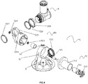
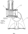
- the present invention discloses a combined shredding and cutting component, which comprises a shredder tube 1 and a feed tube 2, the feed tube is arranged perpendicular to the shredder tube, and the shredder tube comprises a shredder tube shell 11.
- the strip cutter support 12 is arranged in the shredder tube shell, the strip cutter 13 is arranged on the side of the strip cutter support, and the spiral cutter support 14 is clamped on the bottom surface of the strip cutter support, the spiral cutter 15 is arranged on the spiral cutter support, the strip cutter and the spiral cutter are arranged perpendicular to each other.
- the strip cutter support is a cylinder which is open at both ends. On the side wall of the cylinder, two installation positions for installing the strip cutter are symmetrically provided. The shape of the strip cutter matches the installation position on the side wall of the cylinder. There are two pieces of strip cutters, and each strip cutter is semi-cylindrical.
- the spiral cutter 15 comprises a cutter disk 151 which is fixed on the spiral cutter support.
- the centre of the shaft of the cutter disk is provided with a core cutter 152, a slot 153 is formed between the outer edge of the cutter disk and the core cutter, and a slice cutter supporter 154 is arranged on one side of the slot.
- a slice cutter 155 is arranged on the slice cutter support, a triangle cutter 156 is arranged equidistant from and parallel to the slice cutter support on the other side of the slot of the cutter disk.
- the slice cutter support protrudes on the bottom surface of the cutter disk, and the slice cutter parallel to the bottom of the cutter disk.
- the triangle cutter and the slice cutter are arranged perpendicular to each other, and the core cutter protrudes from the triangular cutter.
- the shredder tube When the shredder tube is oriented horizontally, the food is put into the feed tube and cut into strips. When the shredder tube is rotated to a vertical orientation and arranged vertically, the food is put into the feed tube and cut into a spiral.
- the invention provides a shredding and cutting component, which adds the spiral cutter to the bottom of the strip cutter, through a rotation conversion method. In this way it is very convenient to convert between the food shredding mode and the food spiralling mode.
- the present invention discloses a rotary cutting machine, comprising a body base 3, wherein the body base is provided with the combined shredding and cutting component 4 such that the component is capable of rotating about the motor axis of the base by 90°.
- a power unit for powering the shredding cutter components is also provided.
- the power unit is connected to the combined shredding and cutting component.
- the connector 6 for connecting the power unit is provided on one side of the shredder tube.
- the transmission unit connects the drive unit and the connector.
- the feed tube is provided with a complementary pusher 8, which can be inserted into the feed tube to urge food along the feed tube.
- the pusher 8 comprises a first pusher element 81 and a second pusher element 82 each of which can be selected to match the size of the food to be processed.
- the first pusher element can be at least partially sheathed in the second pusher element.
- the combined shredding and cutting component comprising a shredder tube 1 and a feed tube 2, the feed tube is oriented perpendicular to the shredder tube.
- the feeding tube is a cylinder open at two ends, and the shredder tube comprises a shredder tube shell 11, the shredder tube shell is a cylinder that is open at both ends, and the side wall of the shredder tube shell passes through the lower end of the feed tube.
- the strip cutter support 12 is arranged in the shredder tube shell, the strip cutter 13 is arranged on the side of the strip cutter support, and the spiral cutter support 14 is clamped on the bottom surface of the strip cutter support, the spiral cutter 15 is arranged on the spiral cutter support, the strip cutter and the spiral cutter are arranged perpendicular to each other.
- the spiral cutter 15 comprises a cutter disk 151 which is fixed on the spiral cutter support.
- the centre of the shaft of the cutter disk is provided with a core cutter 152, a slot 153 is formed between the outer edge of the cutter disk and the core cutter, and a slice cutter support 154 is arranged on one side of the slot.
- a slice cutter 155 is arranged on the slice cutter support, a triangle cutter 156 is arranged equidistant to and parallel to the slice cutter support on the other side of the slot of the cutter disk.
- the slice cutter support protrudes on the bottom surface of the cutter disk, and the slice cutter parallel to the bottom of the cutter disk.
- the triangle cutter and the slice cutter are arranged perpendicular to each other, and the core cutter protrudes from the triangular cutter.
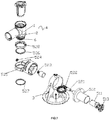
- the drive unit 51 includes a motor 511, a motor shell 512 and a motor lid 513.
- the motor lid is attached to the motor shell, and the motor shell is fixed on the body base.
- the transmission unit 52 comprises a drive shaft 521 connected with a motor, and the connector is provided with a gear set 522 that meshes with the connector.
- the gear set is arranged in parallel with the drive shaft, and a front bearing 523 and a rear bearing 524 are respectively arranged at the front and the back ends of the drive shaft.
- a gear set box 525 matched with the gear set, a first bushing 526 and a second bushing 527 are arranged on either side of the gear set box.
- the gear lid 528 is arranged between the first bushing and connector, and the gear set box is fixed on the base.
- a first limit block 31 and a second limit block 32 are provided on the body base 3 so as to form an arc angle of 90°.
- the first limit block is in an "L" shape and the second limit block is convex block.
- a third limit block 5251 arranged outside the gear set box, is configured to interact with the first limit block and the second limit block so as to limit the rotation of the gear set box 525 relative to the body base 3 to a 0-90° free rotation between the first limit block and the second limit block.
- the third limit block is in an "L" shape.
- the first limit block When cutting the food into a spiral, the first limit block abuts the third limit block; this is the spiral cutting mode. In the strip cutting mode, the inner side of the third limit block abuts the second limit block.
- An adjustment unit 7 is arranged on the outer periphery of the shredder tube shell.
- the adjusting unit comprises an upper cover base 71 fixed on the shredder tube shell. One end of the upper cover base extend beyond the strip cutter support, and the other end of the upper cover base is fixedly connected with the feed tube.
- the locking device 72 is arranged on the upper cover base, and the locking device lid 73 is arranged on the locking device.
- a first spring 74 and a spring rod 75 are provided in the locking device. The first spring is sheathed on the spring rod.
- the locking device lid is provided with a limit slider 76 and a second spring 77.
- the second spring is arranged in the limit slider.
- the main function of the adjustment unit is to safety lock the shredder tube in position.
- the shredder tube In the food strip cutting mode the shredder tube is orientated horizontally.
- the inner side of the third limit block 5251 on the gear set box abuts with the second limit block 32 of the body base.
- Foods can then be fed into the shredder tube and, under the action of the motor the power will be transmitted to the connector by the transmission unit.
- the spiral cutter is driven by the connector to rotate and the food is cut into a spiral by the spiral cutter as the food is urged towards the spiral cutter under the action of the pusher.
- the present invention provides a rotary cutting machine for cutting strips and spirals on a single machine by rotating the shredding and cutting component without the need to replace the power unit and cutter unit.
- the rotary cutting machine can cut spirals and strips on the machine.
- the invention integrates a strip cutter and a spiral cutter in a shredder tube shell, and integrates the two kinds of cuts with different output power modes to facilitate the conversion of the strip cutter and the spiral cutter.
- the invention has the advantages of simple overall structure, convenient operation and high safety performance.
Landscapes
- Engineering & Computer Science (AREA)
- Mechanical Engineering (AREA)
- Food Science & Technology (AREA)
- Life Sciences & Earth Sciences (AREA)
- Forests & Forestry (AREA)
- Crushing And Pulverization Processes (AREA)
- Cookers (AREA)
Applications Claiming Priority (1)
| Application Number | Priority Date | Filing Date | Title |
|---|---|---|---|
| CN201710575625.4A CN109249453B (zh) | 2017-07-14 | 2017-07-14 | 一种二合一切丝组合器及旋转式切丝机 |
Publications (2)
| Publication Number | Publication Date |
|---|---|
| EP3427622A1 true EP3427622A1 (fr) | 2019-01-16 |
| EP3427622B1 EP3427622B1 (fr) | 2020-01-29 |
Family
ID=62486499
Family Applications (1)
| Application Number | Title | Priority Date | Filing Date |
|---|---|---|---|
| EP18174917.7A Active EP3427622B1 (fr) | 2017-07-14 | 2018-05-29 | Machine de découpe rotative |
Country Status (3)
| Country | Link |
|---|---|
| US (2) | US10765262B2 (fr) |
| EP (1) | EP3427622B1 (fr) |
| CN (1) | CN109249453B (fr) |
Cited By (2)
| Publication number | Priority date | Publication date | Assignee | Title |
|---|---|---|---|---|
| CN110403492A (zh) * | 2019-06-24 | 2019-11-05 | 九阳股份有限公司 | 一种食品加工机 |
| EP3689205A1 (fr) * | 2019-02-02 | 2020-08-05 | Koninklijke Philips N.V. | Piston pour appareil de cuisine et appareil de cuisine |
Families Citing this family (9)
| Publication number | Priority date | Publication date | Assignee | Title |
|---|---|---|---|---|
| DE202018006410U1 (de) | 2017-08-09 | 2020-04-23 | Sharkninja Operating Llc | Kochgerät und Komponenten davon |
| US11439264B2 (en) * | 2018-04-17 | 2022-09-13 | Prota Labs, LLC | Apparatuses and methods for cutting, spreading, and/or dispensing food product |
| WO2020176477A1 (fr) | 2019-02-25 | 2020-09-03 | Sharkninja Operating Llc | Système de cuisson avec protection |
| US20190254476A1 (en) | 2019-02-25 | 2019-08-22 | Sharkninja Operating Llc | Cooking device and components thereof |
| CN110100856A (zh) * | 2019-06-24 | 2019-08-09 | 山西大学商务学院 | 自动削面削丝多功能一体机 |
| US11647861B2 (en) | 2020-03-30 | 2023-05-16 | Sharkninja Operating Llc | Cooking device and components thereof |
| US20220234232A1 (en) * | 2021-01-28 | 2022-07-28 | Etn Capital, Llc | Spiralizer Device |
| CN113976558A (zh) * | 2021-10-11 | 2022-01-28 | 六安市叶集区孙岗乡卫生院 | 一种利用高温蒸汽中药药斗清除装置 |
| USD1106776S1 (en) * | 2024-06-22 | 2025-12-23 | Dongguan Tailis Metal Technology Co., Ltd. | Cutting blade for a vegetable cutter |
Citations (5)
| Publication number | Priority date | Publication date | Assignee | Title |
|---|---|---|---|---|
| WO2014067489A1 (fr) * | 2012-11-05 | 2014-05-08 | 北京银河星辰科技有限公司 | Dispositif de traitement d'aliments du type coupant rotatif |
| EP2957200A1 (fr) * | 2014-06-19 | 2015-12-23 | Seb S.A. | Dispositif de preparation d aliments comprenant au moins deux outils de travail |
| US20160101533A1 (en) * | 2014-10-14 | 2016-04-14 | Sunbeam Products, Inc. | Food Processor with Spiralizer Feature |
| WO2017013337A1 (fr) * | 2015-07-20 | 2017-01-26 | Seb S.A. | Dispositif de preparation culinaire comportant au moins un outil de coupe en spirale rotatif |
| WO2017100859A1 (fr) * | 2015-12-18 | 2017-06-22 | Breville Pty Limited | Accessoire de coupe en spirale |
Family Cites Families (30)
| Publication number | Priority date | Publication date | Assignee | Title |
|---|---|---|---|---|
| GB774173A (en) * | 1953-04-18 | 1957-05-08 | Wool Ind Res Association | Machines for sharpening microtome knives or similar cutting blades |
| US4906486A (en) * | 1988-01-19 | 1990-03-06 | Young J Winslow | Apparatus and method for comminuting frozen food items |
| US4884755A (en) * | 1988-08-30 | 1989-12-05 | Presto Industries, Inc. | Food processor |
| US5261613A (en) * | 1993-01-29 | 1993-11-16 | Richard Mullarky | Stationary disc cutting assembly |
| US5364037A (en) * | 1993-06-22 | 1994-11-15 | Nor-Wol Products, Inc. | Electric cheese grater with spring-loaded cheese compartment |
| US5660341A (en) * | 1996-02-15 | 1997-08-26 | The Pampered Chef, Ltd. | Rotary grater |
| US5803378A (en) * | 1996-02-15 | 1998-09-08 | The Pampered Chef, Ltd. | Rotary grater |
| US6244529B1 (en) * | 2000-06-26 | 2001-06-12 | Desing Pierre Tardif Inc. | Manually-operated garlic grater |
| CN2527412Y (zh) * | 2002-03-02 | 2002-12-25 | 刘波 | 多功能切丝切片机 |
| GB2394648B (en) * | 2002-10-29 | 2005-05-25 | Kwok Kuen So | Grating and cutting apparatus |
| US6766731B1 (en) * | 2003-03-27 | 2004-07-27 | Aac Trade Ltd. | Shredding appliance for shredding vegetables or other food articles |
| US7137581B2 (en) * | 2003-08-05 | 2006-11-21 | Zyliss Usa Corp. | Methods and apparatus for an improved rotary grater |
| US7337997B2 (en) * | 2005-03-21 | 2008-03-04 | Merry Chance Industries, Ltd. | Food slicing device |
| DE602006006906D1 (de) * | 2006-07-21 | 2009-07-02 | Kwok Kuen So | Schneidvorrichtung für Lebensmittelprodukte |
| US8579852B2 (en) * | 2006-09-14 | 2013-11-12 | Omeed Memar | Apparatus and methods for repairing tissue defects |
| RU2433349C1 (ru) * | 2007-08-08 | 2011-11-10 | Шарп Кабусики Кайся | Пароварочный аппарат |
| US20100270406A1 (en) * | 2009-04-27 | 2010-10-28 | Grace Manufacturing Inc. | Enhanced hand operated grater |
| FR2963548B1 (fr) * | 2010-08-06 | 2012-08-31 | Seb Sa | Accessoires de decoupe d'aliments a deversement ameliore et appareil electromenager comportant de tels accessoires |
| FR2965710B1 (fr) * | 2010-10-07 | 2012-11-02 | Seb Sa | Dispositif de rangement pour outils de decoupe emboitables et appareil electromenager comportant un tel dispositif |
| US8973854B2 (en) * | 2010-10-31 | 2015-03-10 | Abdoolally Ebrahim Housewares Limited | Food grater |
| US8567704B2 (en) * | 2011-02-08 | 2013-10-29 | Progressive International Corporation | Rotary grater |
| FR2975936B1 (fr) * | 2011-06-01 | 2013-06-28 | Seb Sa | Outil de coupe d'aliments en morceaux |
| CN202312827U (zh) * | 2011-11-21 | 2012-07-11 | 惠阳亚伦塑胶电器实业有限公司 | 一种分体式电蒸煲 |
| US10364992B2 (en) * | 2013-09-05 | 2019-07-30 | Alto-Shaam, Inc. | Ventless oven hood for combination oven providing rapid access |
| FR3015211B1 (fr) * | 2013-12-20 | 2016-01-29 | Seb Sa | Dispositif de fragmentation d’aliments et d’ejection d’aliments fragmentes |
| CN105234989B (zh) * | 2015-11-24 | 2017-10-17 | 刘可心 | 一种多用蔬菜切丝装置 |
| CN205704389U (zh) * | 2016-04-15 | 2016-11-23 | 深圳市联创三金电器有限公司 | 设置有两种进料口的多功能切丝切片装置 |
| CN205735178U (zh) * | 2016-05-06 | 2016-11-30 | 深圳市联创三金电器有限公司 | 多功能电动切丝切片装置 |
| CN106863413A (zh) * | 2017-04-07 | 2017-06-20 | 朱九维 | 一种切食材装置 |
| CN206883727U9 (zh) * | 2017-07-14 | 2018-04-13 | 惠阳亚伦塑胶电器实业有限公司 | 一种二合一切丝组合器及旋转式切丝机 |
-
2017
- 2017-07-14 CN CN201710575625.4A patent/CN109249453B/zh active Active
-
2018
- 2018-05-29 EP EP18174917.7A patent/EP3427622B1/fr active Active
- 2018-07-11 US US16/033,103 patent/US10765262B2/en active Active
- 2018-07-11 US US16/033,139 patent/US20190014940A1/en not_active Abandoned
Patent Citations (5)
| Publication number | Priority date | Publication date | Assignee | Title |
|---|---|---|---|---|
| WO2014067489A1 (fr) * | 2012-11-05 | 2014-05-08 | 北京银河星辰科技有限公司 | Dispositif de traitement d'aliments du type coupant rotatif |
| EP2957200A1 (fr) * | 2014-06-19 | 2015-12-23 | Seb S.A. | Dispositif de preparation d aliments comprenant au moins deux outils de travail |
| US20160101533A1 (en) * | 2014-10-14 | 2016-04-14 | Sunbeam Products, Inc. | Food Processor with Spiralizer Feature |
| WO2017013337A1 (fr) * | 2015-07-20 | 2017-01-26 | Seb S.A. | Dispositif de preparation culinaire comportant au moins un outil de coupe en spirale rotatif |
| WO2017100859A1 (fr) * | 2015-12-18 | 2017-06-22 | Breville Pty Limited | Accessoire de coupe en spirale |
Cited By (4)
| Publication number | Priority date | Publication date | Assignee | Title |
|---|---|---|---|---|
| EP3689205A1 (fr) * | 2019-02-02 | 2020-08-05 | Koninklijke Philips N.V. | Piston pour appareil de cuisine et appareil de cuisine |
| CN111513572A (zh) * | 2019-02-02 | 2020-08-11 | 皇家飞利浦有限公司 | 厨房用具的活塞和厨房用具 |
| CN110403492A (zh) * | 2019-06-24 | 2019-11-05 | 九阳股份有限公司 | 一种食品加工机 |
| CN110403492B (zh) * | 2019-06-24 | 2022-03-15 | 九阳股份有限公司 | 一种食品加工机 |
Also Published As
| Publication number | Publication date |
|---|---|
| EP3427622B1 (fr) | 2020-01-29 |
| US20190014947A1 (en) | 2019-01-17 |
| CN109249453B (zh) | 2024-04-02 |
| US20190014940A1 (en) | 2019-01-17 |
| US10765262B2 (en) | 2020-09-08 |
| CN109249453A (zh) | 2019-01-22 |
Similar Documents
| Publication | Publication Date | Title |
|---|---|---|
| EP3427622B1 (fr) | Machine de découpe rotative | |
| US10786119B2 (en) | Multi-function food processing device | |
| US10780602B2 (en) | Clamping assemblies and slicing machines equipped therewith | |
| EP3802028B1 (fr) | Couteaux et ensembles couteaux destinés à des machines à trancher et machines à trancher dotées de ces derniers | |
| CN107599015B (zh) | 一种小型切肉机 | |
| US11717114B2 (en) | Multifunctional food processor | |
| CN205915391U (zh) | 多功能电动切丝切片装置 | |
| CN217826559U (zh) | 一种切肉机 | |
| CN206264022U (zh) | 食品刨切机 | |
| CN210303974U (zh) | 一种实心刀辊以及具有实心刀辊的破碎机 | |
| CN107960907B (zh) | 食物处理器 | |
| CN206883727U9 (zh) | 一种二合一切丝组合器及旋转式切丝机 | |
| CN107529429A (zh) | 一种多功能食物刨丝切片及搅拌一体机 | |
| CN218699277U (zh) | 多刀切片机 | |
| CN221129710U (zh) | 食物处理器 | |
| CN218576449U (zh) | 一种切片刨丝一体机 | |
| CN109807979B (zh) | 一种食物处理器 | |
| CN221750234U (zh) | 可切换进料筒角度的沙拉机 | |
| CN206565844U (zh) | 食物处理器 | |
| CN108068150A (zh) | 食品刨切机 | |
| CN220654611U (zh) | 一种砍排机传动机构 | |
| CN220994696U (zh) | 切片装置及切片机 | |
| CN114274190A (zh) | 一种多功能切菜机 | |
| CN208392160U (zh) | 一种果蔬切片机 | |
| CN204970966U (zh) | 用于食物加工装置上的切割工具 |
Legal Events
| Date | Code | Title | Description |
|---|---|---|---|
| PUAI | Public reference made under article 153(3) epc to a published international application that has entered the european phase |
Free format text: ORIGINAL CODE: 0009012 |
|
| STAA | Information on the status of an ep patent application or granted ep patent |
Free format text: STATUS: THE APPLICATION HAS BEEN PUBLISHED |
|
| AK | Designated contracting states |
Kind code of ref document: A1 Designated state(s): AL AT BE BG CH CY CZ DE DK EE ES FI FR GB GR HR HU IE IS IT LI LT LU LV MC MK MT NL NO PL PT RO RS SE SI SK SM TR |
|
| AX | Request for extension of the european patent |
Extension state: BA ME |
|
| STAA | Information on the status of an ep patent application or granted ep patent |
Free format text: STATUS: REQUEST FOR EXAMINATION WAS MADE |
|
| 17P | Request for examination filed |
Effective date: 20190523 |
|
| RBV | Designated contracting states (corrected) |
Designated state(s): AL AT BE BG CH CY CZ DE DK EE ES FI FR GB GR HR HU IE IS IT LI LT LU LV MC MK MT NL NO PL PT RO RS SE SI SK SM TR |
|
| RAP1 | Party data changed (applicant data changed or rights of an application transferred) |
Owner name: HUIYANG ALLAN PLASTIC & ELECTRIC INDUSTRIES CO., L |
|
| GRAP | Despatch of communication of intention to grant a patent |
Free format text: ORIGINAL CODE: EPIDOSNIGR1 |
|
| STAA | Information on the status of an ep patent application or granted ep patent |
Free format text: STATUS: GRANT OF PATENT IS INTENDED |
|
| RIC1 | Information provided on ipc code assigned before grant |
Ipc: A47J 43/046 20060101ALI20191009BHEP Ipc: A47J 43/07 20060101ALI20191009BHEP Ipc: A47J 43/25 20060101AFI20191009BHEP |
|
| INTG | Intention to grant announced |
Effective date: 20191025 |
|
| GRAS | Grant fee paid |
Free format text: ORIGINAL CODE: EPIDOSNIGR3 |
|
| GRAA | (expected) grant |
Free format text: ORIGINAL CODE: 0009210 |
|
| STAA | Information on the status of an ep patent application or granted ep patent |
Free format text: STATUS: THE PATENT HAS BEEN GRANTED |
|
| AK | Designated contracting states |
Kind code of ref document: B1 Designated state(s): AL AT BE BG CH CY CZ DE DK EE ES FI FR GB GR HR HU IE IS IT LI LT LU LV MC MK MT NL NO PL PT RO RS SE SI SK SM TR |
|
| REG | Reference to a national code |
Ref country code: GB Ref legal event code: FG4D |
|
| REG | Reference to a national code |
Ref country code: CH Ref legal event code: EP |
|
| REG | Reference to a national code |
Ref country code: AT Ref legal event code: REF Ref document number: 1227896 Country of ref document: AT Kind code of ref document: T Effective date: 20200215 |
|
| REG | Reference to a national code |
Ref country code: IE Ref legal event code: FG4D |
|
| REG | Reference to a national code |
Ref country code: DE Ref legal event code: R096 Ref document number: 602018002214 Country of ref document: DE |
|
| REG | Reference to a national code |
Ref country code: NL Ref legal event code: MP Effective date: 20200129 |
|
| PG25 | Lapsed in a contracting state [announced via postgrant information from national office to epo] |
Ref country code: NO Free format text: LAPSE BECAUSE OF FAILURE TO SUBMIT A TRANSLATION OF THE DESCRIPTION OR TO PAY THE FEE WITHIN THE PRESCRIBED TIME-LIMIT Effective date: 20200429 Ref country code: PT Free format text: LAPSE BECAUSE OF FAILURE TO SUBMIT A TRANSLATION OF THE DESCRIPTION OR TO PAY THE FEE WITHIN THE PRESCRIBED TIME-LIMIT Effective date: 20200621 Ref country code: RS Free format text: LAPSE BECAUSE OF FAILURE TO SUBMIT A TRANSLATION OF THE DESCRIPTION OR TO PAY THE FEE WITHIN THE PRESCRIBED TIME-LIMIT Effective date: 20200129 Ref country code: FI Free format text: LAPSE BECAUSE OF FAILURE TO SUBMIT A TRANSLATION OF THE DESCRIPTION OR TO PAY THE FEE WITHIN THE PRESCRIBED TIME-LIMIT Effective date: 20200129 |
|
| REG | Reference to a national code |
Ref country code: LT Ref legal event code: MG4D |
|
| PG25 | Lapsed in a contracting state [announced via postgrant information from national office to epo] |
Ref country code: HR Free format text: LAPSE BECAUSE OF FAILURE TO SUBMIT A TRANSLATION OF THE DESCRIPTION OR TO PAY THE FEE WITHIN THE PRESCRIBED TIME-LIMIT Effective date: 20200129 Ref country code: SE Free format text: LAPSE BECAUSE OF FAILURE TO SUBMIT A TRANSLATION OF THE DESCRIPTION OR TO PAY THE FEE WITHIN THE PRESCRIBED TIME-LIMIT Effective date: 20200129 Ref country code: LV Free format text: LAPSE BECAUSE OF FAILURE TO SUBMIT A TRANSLATION OF THE DESCRIPTION OR TO PAY THE FEE WITHIN THE PRESCRIBED TIME-LIMIT Effective date: 20200129 Ref country code: GR Free format text: LAPSE BECAUSE OF FAILURE TO SUBMIT A TRANSLATION OF THE DESCRIPTION OR TO PAY THE FEE WITHIN THE PRESCRIBED TIME-LIMIT Effective date: 20200430 Ref country code: IS Free format text: LAPSE BECAUSE OF FAILURE TO SUBMIT A TRANSLATION OF THE DESCRIPTION OR TO PAY THE FEE WITHIN THE PRESCRIBED TIME-LIMIT Effective date: 20200529 Ref country code: BG Free format text: LAPSE BECAUSE OF FAILURE TO SUBMIT A TRANSLATION OF THE DESCRIPTION OR TO PAY THE FEE WITHIN THE PRESCRIBED TIME-LIMIT Effective date: 20200429 |
|
| PG25 | Lapsed in a contracting state [announced via postgrant information from national office to epo] |
Ref country code: NL Free format text: LAPSE BECAUSE OF FAILURE TO SUBMIT A TRANSLATION OF THE DESCRIPTION OR TO PAY THE FEE WITHIN THE PRESCRIBED TIME-LIMIT Effective date: 20200129 |
|
| PG25 | Lapsed in a contracting state [announced via postgrant information from national office to epo] |
Ref country code: CZ Free format text: LAPSE BECAUSE OF FAILURE TO SUBMIT A TRANSLATION OF THE DESCRIPTION OR TO PAY THE FEE WITHIN THE PRESCRIBED TIME-LIMIT Effective date: 20200129 Ref country code: ES Free format text: LAPSE BECAUSE OF FAILURE TO SUBMIT A TRANSLATION OF THE DESCRIPTION OR TO PAY THE FEE WITHIN THE PRESCRIBED TIME-LIMIT Effective date: 20200129 Ref country code: RO Free format text: LAPSE BECAUSE OF FAILURE TO SUBMIT A TRANSLATION OF THE DESCRIPTION OR TO PAY THE FEE WITHIN THE PRESCRIBED TIME-LIMIT Effective date: 20200129 Ref country code: DK Free format text: LAPSE BECAUSE OF FAILURE TO SUBMIT A TRANSLATION OF THE DESCRIPTION OR TO PAY THE FEE WITHIN THE PRESCRIBED TIME-LIMIT Effective date: 20200129 Ref country code: LT Free format text: LAPSE BECAUSE OF FAILURE TO SUBMIT A TRANSLATION OF THE DESCRIPTION OR TO PAY THE FEE WITHIN THE PRESCRIBED TIME-LIMIT Effective date: 20200129 Ref country code: SM Free format text: LAPSE BECAUSE OF FAILURE TO SUBMIT A TRANSLATION OF THE DESCRIPTION OR TO PAY THE FEE WITHIN THE PRESCRIBED TIME-LIMIT Effective date: 20200129 Ref country code: EE Free format text: LAPSE BECAUSE OF FAILURE TO SUBMIT A TRANSLATION OF THE DESCRIPTION OR TO PAY THE FEE WITHIN THE PRESCRIBED TIME-LIMIT Effective date: 20200129 Ref country code: SK Free format text: LAPSE BECAUSE OF FAILURE TO SUBMIT A TRANSLATION OF THE DESCRIPTION OR TO PAY THE FEE WITHIN THE PRESCRIBED TIME-LIMIT Effective date: 20200129 |
|
| REG | Reference to a national code |
Ref country code: DE Ref legal event code: R097 Ref document number: 602018002214 Country of ref document: DE |
|
| REG | Reference to a national code |
Ref country code: AT Ref legal event code: MK05 Ref document number: 1227896 Country of ref document: AT Kind code of ref document: T Effective date: 20200129 |
|
| PLBE | No opposition filed within time limit |
Free format text: ORIGINAL CODE: 0009261 |
|
| STAA | Information on the status of an ep patent application or granted ep patent |
Free format text: STATUS: NO OPPOSITION FILED WITHIN TIME LIMIT |
|
| 26N | No opposition filed |
Effective date: 20201030 |
|
| PG25 | Lapsed in a contracting state [announced via postgrant information from national office to epo] |
Ref country code: AT Free format text: LAPSE BECAUSE OF FAILURE TO SUBMIT A TRANSLATION OF THE DESCRIPTION OR TO PAY THE FEE WITHIN THE PRESCRIBED TIME-LIMIT Effective date: 20200129 Ref country code: IT Free format text: LAPSE BECAUSE OF FAILURE TO SUBMIT A TRANSLATION OF THE DESCRIPTION OR TO PAY THE FEE WITHIN THE PRESCRIBED TIME-LIMIT Effective date: 20200129 Ref country code: MC Free format text: LAPSE BECAUSE OF FAILURE TO SUBMIT A TRANSLATION OF THE DESCRIPTION OR TO PAY THE FEE WITHIN THE PRESCRIBED TIME-LIMIT Effective date: 20200129 |
|
| PG25 | Lapsed in a contracting state [announced via postgrant information from national office to epo] |
Ref country code: PL Free format text: LAPSE BECAUSE OF FAILURE TO SUBMIT A TRANSLATION OF THE DESCRIPTION OR TO PAY THE FEE WITHIN THE PRESCRIBED TIME-LIMIT Effective date: 20200129 Ref country code: SI Free format text: LAPSE BECAUSE OF FAILURE TO SUBMIT A TRANSLATION OF THE DESCRIPTION OR TO PAY THE FEE WITHIN THE PRESCRIBED TIME-LIMIT Effective date: 20200129 |
|
| REG | Reference to a national code |
Ref country code: BE Ref legal event code: MM Effective date: 20200531 |
|
| PG25 | Lapsed in a contracting state [announced via postgrant information from national office to epo] |
Ref country code: LU Free format text: LAPSE BECAUSE OF NON-PAYMENT OF DUE FEES Effective date: 20200529 |
|
| PG25 | Lapsed in a contracting state [announced via postgrant information from national office to epo] |
Ref country code: IE Free format text: LAPSE BECAUSE OF NON-PAYMENT OF DUE FEES Effective date: 20200529 Ref country code: FR Free format text: LAPSE BECAUSE OF NON-PAYMENT OF DUE FEES Effective date: 20200531 |
|
| PG25 | Lapsed in a contracting state [announced via postgrant information from national office to epo] |
Ref country code: BE Free format text: LAPSE BECAUSE OF NON-PAYMENT OF DUE FEES Effective date: 20200531 |
|
| REG | Reference to a national code |
Ref country code: CH Ref legal event code: PL |
|
| PG25 | Lapsed in a contracting state [announced via postgrant information from national office to epo] |
Ref country code: CH Free format text: LAPSE BECAUSE OF NON-PAYMENT OF DUE FEES Effective date: 20210531 Ref country code: LI Free format text: LAPSE BECAUSE OF NON-PAYMENT OF DUE FEES Effective date: 20210531 |
|
| PG25 | Lapsed in a contracting state [announced via postgrant information from national office to epo] |
Ref country code: TR Free format text: LAPSE BECAUSE OF FAILURE TO SUBMIT A TRANSLATION OF THE DESCRIPTION OR TO PAY THE FEE WITHIN THE PRESCRIBED TIME-LIMIT Effective date: 20200129 Ref country code: MT Free format text: LAPSE BECAUSE OF FAILURE TO SUBMIT A TRANSLATION OF THE DESCRIPTION OR TO PAY THE FEE WITHIN THE PRESCRIBED TIME-LIMIT Effective date: 20200129 Ref country code: CY Free format text: LAPSE BECAUSE OF FAILURE TO SUBMIT A TRANSLATION OF THE DESCRIPTION OR TO PAY THE FEE WITHIN THE PRESCRIBED TIME-LIMIT Effective date: 20200129 |
|
| PG25 | Lapsed in a contracting state [announced via postgrant information from national office to epo] |
Ref country code: MK Free format text: LAPSE BECAUSE OF FAILURE TO SUBMIT A TRANSLATION OF THE DESCRIPTION OR TO PAY THE FEE WITHIN THE PRESCRIBED TIME-LIMIT Effective date: 20200129 Ref country code: AL Free format text: LAPSE BECAUSE OF FAILURE TO SUBMIT A TRANSLATION OF THE DESCRIPTION OR TO PAY THE FEE WITHIN THE PRESCRIBED TIME-LIMIT Effective date: 20200129 |
|
| GBPC | Gb: european patent ceased through non-payment of renewal fee |
Effective date: 20220529 |
|
| PG25 | Lapsed in a contracting state [announced via postgrant information from national office to epo] |
Ref country code: GB Free format text: LAPSE BECAUSE OF NON-PAYMENT OF DUE FEES Effective date: 20220529 |
|
| PGFP | Annual fee paid to national office [announced via postgrant information from national office to epo] |
Ref country code: DE Payment date: 20250521 Year of fee payment: 8 |