EP3427984B2 - Dispositif de protection d'habitacle de véhicule - Google Patents
Dispositif de protection d'habitacle de véhicule Download PDFInfo
- Publication number
- EP3427984B2 EP3427984B2 EP18177327.6A EP18177327A EP3427984B2 EP 3427984 B2 EP3427984 B2 EP 3427984B2 EP 18177327 A EP18177327 A EP 18177327A EP 3427984 B2 EP3427984 B2 EP 3427984B2
- Authority
- EP
- European Patent Office
- Prior art keywords
- protective device
- plug
- receptacles
- guide member
- sections
- Prior art date
- Legal status (The legal status is an assumption and is not a legal conclusion. Google has not performed a legal analysis and makes no representation as to the accuracy of the status listed.)
- Active
Links
Images


Classifications
-
- B—PERFORMING OPERATIONS; TRANSPORTING
- B60—VEHICLES IN GENERAL
- B60J—WINDOWS, WINDSCREENS, NON-FIXED ROOFS, DOORS, OR SIMILAR DEVICES FOR VEHICLES; REMOVABLE EXTERNAL PROTECTIVE COVERINGS SPECIALLY ADAPTED FOR VEHICLES
- B60J7/00—Non-fixed roofs; Roofs with movable panels, e.g. rotary sunroofs
- B60J7/02—Non-fixed roofs; Roofs with movable panels, e.g. rotary sunroofs of sliding type, e.g. comprising guide shoes
- B60J7/04—Non-fixed roofs; Roofs with movable panels, e.g. rotary sunroofs of sliding type, e.g. comprising guide shoes with rigid plate-like element or elements, e.g. open roofs with harmonica-type folding rigid panels
- B60J7/043—Sunroofs e.g. sliding above the roof
-
- B—PERFORMING OPERATIONS; TRANSPORTING
- B60—VEHICLES IN GENERAL
- B60J—WINDOWS, WINDSCREENS, NON-FIXED ROOFS, DOORS, OR SIMILAR DEVICES FOR VEHICLES; REMOVABLE EXTERNAL PROTECTIVE COVERINGS SPECIALLY ADAPTED FOR VEHICLES
- B60J7/00—Non-fixed roofs; Roofs with movable panels, e.g. rotary sunroofs
- B60J7/0007—Non-fixed roofs; Roofs with movable panels, e.g. rotary sunroofs moveable head-liners, screens, curtains or blinds for ceilings
- B60J7/0015—Non-fixed roofs; Roofs with movable panels, e.g. rotary sunroofs moveable head-liners, screens, curtains or blinds for ceilings roller blind
-
- B—PERFORMING OPERATIONS; TRANSPORTING
- B60—VEHICLES IN GENERAL
- B60J—WINDOWS, WINDSCREENS, NON-FIXED ROOFS, DOORS, OR SIMILAR DEVICES FOR VEHICLES; REMOVABLE EXTERNAL PROTECTIVE COVERINGS SPECIALLY ADAPTED FOR VEHICLES
- B60J1/00—Windows; Windscreens; Accessories therefor
- B60J1/20—Accessories, e.g. wind deflectors, blinds
-
- B—PERFORMING OPERATIONS; TRANSPORTING
- B60—VEHICLES IN GENERAL
- B60J—WINDOWS, WINDSCREENS, NON-FIXED ROOFS, DOORS, OR SIMILAR DEVICES FOR VEHICLES; REMOVABLE EXTERNAL PROTECTIVE COVERINGS SPECIALLY ADAPTED FOR VEHICLES
- B60J1/00—Windows; Windscreens; Accessories therefor
- B60J1/20—Accessories, e.g. wind deflectors, blinds
- B60J1/2011—Blinds; curtains or screens reducing heat or light intensity
- B60J1/2013—Roller blinds
- B60J1/2036—Roller blinds characterised by structural elements
- B60J1/2052—Guides
-
- B—PERFORMING OPERATIONS; TRANSPORTING
- B60—VEHICLES IN GENERAL
- B60J—WINDOWS, WINDSCREENS, NON-FIXED ROOFS, DOORS, OR SIMILAR DEVICES FOR VEHICLES; REMOVABLE EXTERNAL PROTECTIVE COVERINGS SPECIALLY ADAPTED FOR VEHICLES
- B60J1/00—Windows; Windscreens; Accessories therefor
- B60J1/20—Accessories, e.g. wind deflectors, blinds
- B60J1/2011—Blinds; curtains or screens reducing heat or light intensity
- B60J1/2013—Roller blinds
- B60J1/2036—Roller blinds characterised by structural elements
- B60J1/2044—Draw bars, including elements attached to it, e.g. sliding shoes, gripping elements or pull cords
-
- B—PERFORMING OPERATIONS; TRANSPORTING
- B60—VEHICLES IN GENERAL
- B60J—WINDOWS, WINDSCREENS, NON-FIXED ROOFS, DOORS, OR SIMILAR DEVICES FOR VEHICLES; REMOVABLE EXTERNAL PROTECTIVE COVERINGS SPECIALLY ADAPTED FOR VEHICLES
- B60J1/00—Windows; Windscreens; Accessories therefor
- B60J1/20—Accessories, e.g. wind deflectors, blinds
- B60J1/2011—Blinds; curtains or screens reducing heat or light intensity
- B60J1/2013—Roller blinds
- B60J1/2036—Roller blinds characterised by structural elements
- B60J1/2061—Tensioning systems for keeping the blind taut when in use, other than spring motors
Definitions
- the invention relates to a protective device for a vehicle interior with a flexible sheet-like structure that can be displaced longitudinally between different functional positions in the vehicle interior and that is provided with a stiffening band on opposite side edges, which are guided longitudinally displaceably in guide tracks fixed to the vehicle, and with an extension profile that extends transversely to the longitudinal displacement direction of the sheet-like structure and is connected to a front end region of the sheet-like structure that is at the front in the extension direction, wherein the extension profile is guided in the vehicle-fixed guide tracks by means of a guide member in each case, and wherein each stiffening band is fastened to a guide member on the front side.
- a protective device in the form of a roller blind arrangement in which a roller blind is provided with a stiffening strip on opposite long sides.
- the stiffening strip is used for guidance in a guide track fixed to the vehicle.
- a driver is provided on the front side of the stiffening strip, which is firmly connected to the stiffening strip and can be coupled to a roller blind coupling.
- the driver has two profile sections that engage positively in two complementary profile receptacles of the roller blind coupling in order to be able to be driven along the guide track with the roller blind coupling.
- a flexible surface structure in the form of a shading sheet is held on a winding shaft so that it can be wound up and unwound.
- the shading sheet is provided with a stiffening strip on each of its opposite side edges.
- the stiffening strips are guided longitudinally in guide profiles fixed to the roof.
- Each stiffening strip is also attached to a guide member at the front, which is guided longitudinally in the respective guide profile fixed to the roof.
- An extension profile is hinged to the guide members, which extends transversely to the longitudinal displacement direction of the shading sheet and is attached to the front of the shading sheet.
- the object of the invention is to provide a protective device of the type mentioned at the outset, which enables an improved connection of the stiffening bands to the guide members.
- the at least three profile sections spaced apart from one another in the longitudinal displacement direction enable an improved connection between the respective guide member and the front end region of the stiffening band. This prevents the stiffening band from becoming unintentionally detached from the guide member.
- the solution according to the invention enables an improved and low-wear fastening of the stiffening bands compared to the prior art. This provides increased functional reliability of the protective device.
- the protective device according to the invention can be provided for shading transparent surfaces of the vehicle interior, such as in particular a transparent glass roof area, a rear window, side windows or the like. Alternatively, the protective device according to the invention can be provided for separating and/or covering a loading space of the vehicle interior.
- the receptacles provided one behind the other in the longitudinal displacement direction can be designed as at least partially closed recessed sides or as open passages facing one another. If they are designed as recesses, these can be designed in the form of impressions or the like.
- the profiling sections are preferably designed with respect to their cross-section complementary to corresponding free cross-sections of the receptacles in order to enable the profiling sections to be inserted into the receptacles with at least a largely play-free manner.
- the profiling sections are arranged on a holding part that is connected to the guide member.
- the profiling sections are preferably formed integrally on the holding part.
- the holding part is advantageously made of plastic.
- the profiling sections protrude from the holding part to one side.
- the holding part is preferably positioned in the area of an underside of the respective stiffening band and the profiling sections protrude upwards through the receptacles of the stiffening band.
- the profiling sections are pin-shaped.
- the receptacles of the stiffening band are designed as passages which have passage cross-sections complementary to the pin-shaped profiling sections.
- the pin-shaped profiling sections and the passages each have circular cross-sections.
- the circular cross-sections are easy to produce and enable contact between profiling sections and passages that is at least largely free of play.
- the pin-shaped profiling sections are advantageously arranged in a row one behind the other in the longitudinal displacement direction.
- the profiling sections advantageously extend in a common plane that runs orthogonally and along a surface of the respective stiffening band.
- the holding part has a connecting section for securing the holding part to the guide member.
- the holding part represents a component separate from the respective guide member
- the holding part and the respective front end region of the stiffening band are connected to one another in a pre-assembly step before the holding part is subsequently connected to the guide member.
- the connecting section is preferably designed in such a way that a tool-free connection of the holding part to the guide member is possible.
- the guide member is provided with a receiving profile for fastening the connecting section to the guide member.
- the receiving profile is designed as a plug-in groove
- the connecting section has a plug-in contour that is complementary to the plug-in groove.
- the plug-in groove is advantageously open towards a front side of the guide member that is directed in the longitudinal displacement direction. This allows the connecting section of the holding part to be inserted into the plug-in groove via the open front side.
- the plug-in groove therefore advantageously extends in the longitudinal displacement direction.
- At least one elastically flexible locking element is provided on the connecting section or the receiving profile, which positively secures the connecting section in the inserted end position in the plug-in groove.
- the plug-in groove preferably has an end stop in the insertion direction, against which the connecting section of the holding part strikes when inserted into the plug-in groove.
- the elastically flexible locking element is designed in such a way that it locks into its locking position as soon as the connecting section has reached its inserted end position in the plug-in groove.
- the plug-in groove preferably has a locking profile complementary to the locking element, into which the elastically flexible locking element locks in the end position of the connecting section.
- the holding part has two partial areas which, when assembled, flank the stiffening band on both sides. Both partial areas are preferably made of plastic.
- the stiffening band can be designed as a flat steel band or as a fiber-reinforced plastic band, in particular as a Teflon band.
- the partial areas are connected to one another in an articulated manner by means of a hinge.
- the hinge defines a pivot axis that runs transversely to the longitudinal displacement direction of the stiffening band, but in or parallel to a plane of the stiffening band.
- the hinge is preferably designed as a film hinge.
- the pin-shaped profiling sections and the plug-in receptacles are curved in the same direction in a common plane.
- the common plane is preferably formed by a radial plane of the pivot axis of the hinge.
- the profiling sections and the plug-in receptacles are curved in the shape of a circular arc corresponding to different circular arcs which have a common center in the common plane, namely a pivot axis of the hinge, and whose radii correspond to the distances of the respective profiling sections or plug-in receptacles from the center. This ensures that when the two partial areas of the holding part are pivoted against each other, the profiling sections are inserted exactly into the plug-in receptacles with a largely constant load.
- the profiling sections and the complementary plug-in receptacles can advantageously be provided with locking profiles at the end to enable the profiling sections to snap into place and thus secure them in the plug-in receptacles in the joined final position of the two partial areas of the holding part.
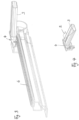
- a protective device 1 according to the Fig. 1 to 10 is intended as a shading device for a glass roof area of a passenger car.
- the shading device is provided in the vehicle interior below the glass roof area and has a flexible surface structure 2, which is also referred to as a shading sheet.
- the flexible surface structure 2 is held on a winding shaft so that it can be wound up and unwound, which is mounted in a cassette housing K ( Fig. 8 ) is rotatably mounted.
- the flexible surface structure 2 is provided on its opposite side edges with a stiffening band 7, which is guided longitudinally displaceably in a guide track fixed to the roof and thus to the vehicle in the form of a guide rail 6. Based on the Fig. 1 to 10 only one of the roof-mounted guide rails 6 is shown.
- An opposite side of the protective device 1 including the guide rail 6 is mirror-symmetrical relative to a vertical central longitudinal axis, but otherwise identical in design. To avoid repetition, only one side is shown below using the drawings according to the Fig. 1 to 10 described. The same applies to the opposite side.
- the flexible sheet 2 can be moved along the guide rails 6 between a rest position wound onto the winding shaft, i.e. a first functional position, and a second functional position extended to an end area of the guide rails 6.
- the flexible sheet 2 is connected at its front end area in the extension direction to a dimensionally stable extension profile 3, which extends transversely across the width of the sheet 2. Based on the Fig. 1 the pull-out profile 3 is shown in two different positions.
- the pull-out profile 3 is coupled at its opposite ends to a guide member 4, which is guided longitudinally in the respective guide rail 6.
- the guide member 4 can be moved longitudinally in the respective guide rail 6 by means of a drive system.
- a longitudinal displacement of the pull-out profile 3 and thus of the guide members 4 can also be carried out manually by appropriately grasping the pull-out profile 3 and moving it along the guide rails 6.
- the respective stiffening band 7 is firmly connected to the guide member 4 in order to be able to be carried along by the guide member 4.
- the stiffening band 7 is designed as a flat band and is made of steel or a fiber-reinforced plastic strip.
- the stiffening band 7 is wound onto the winding shaft in the area of the cassette housing K together with the flexible sheet material and is pulled off from it.
- the stiffening band 7 protrudes beyond the flexible sheet material 2 at its front end area in the pull-out direction (see Fig. 5 to 7 ).
- the stiffening strip 7 is perforated in this area by a total of five holes, which represent passages 8 in the sense of the invention.
- the passages 8 are designed identically to one another and are arranged in a row at equal distances one behind the other.
- All passages 8 are circular and are preferably produced by punching.
- the front end area of the stiffening strip 7 is connected to a holding part 9 in the manner described in more detail below, which is then inserted into a receiving profile 17 of the guide member 4.
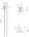
- the holding part 9 consists of an upper part 12 and a lower part 10, which are pivotally connected to one another via a film hinge 11.
- a pivot axis formed by the film hinge 11 extends parallel to a transverse extension of the pull-out profile 3.
- the lower part 10 is provided with a total of five pin-shaped profile sections 16, which protrude from the strip-shaped part 10 towards a common side. In the representation according to the Fig. 5 and 6 the pin-shaped profiling sections 16 protrude downwards.
- the upper portion 12 has five plug-in receptacles 15 complementary to the pin-shaped profiling sections 16, which have at least partially complementary plug-in cross-sections to the cross-sections of the pin-shaped profiling sections 16.
- the upper holding area 12 is first placed on the front end area of the stiffening band 7 until the plug-in receptacles 15 are aligned with the passages 8.
- the film hinge 11 is in this position ( Fig. 6 ) approximately at the level of a front edge of the stiffening band 7.
- the lower part 10 which still extends forwards like a tongue from the upper part 12, is cut out according to the arrow in Fig. 6 pivoted downwards, whereby the five pin-shaped profiling sections 16 pass through the passages 8 arranged one behind the other and into the plug receptacles 15.
- both the plug-in receptacles 15 and the pin-shaped profiling sections 16 extend in a radial plane to the pivot axis formed by the film hinge 11
- the Fig. 10 It can be seen that all pin-shaped profile sections 16 and the associated plug-in receptacles 15 are curved in the shape of a circular arc. The circular arcs have different radii that correspond to the different distances of the individual pin-shaped profile sections 16 from the pivot axis formed by the film hinge 11.
- the circular arc curvature of the pin-shaped profile sections and the associated plug-in receptacles decreases in proportion to the distance that the individual profile sections and plug-in receptacles have from the pivot axis of the film hinge 11.
- the tongue that forms the film hinge 11 extends in the fully assembled state of the holding part 9 (see Fig. 7 and 10 ) around the front edge of the stiffening band 7.
- the pin-shaped profiling sections 16 are either held in the plug-in receptacles 15 in a purely force-fitting manner, or the profiling sections 16 and the complementary plug-in receptacles 15 are assigned additional locking profiles (not shown in detail) which secure the inserted end position of the profiling sections 16 and plug-in receptacles 15. Since the profiling sections 16 are also inserted through the passages 8 of the stiffening band 7 in a form-fitting manner, the holding part 9 is firmly connected to the stiffening band 7.
- the holding part 9 is additionally provided in the upper part 12 with a connecting section 13, which is designed as an essentially T-shaped profile.
- the guide member 4 has a complementary receiving profile 17, which is provided with a complementary T-shaped plug-in groove, which is open to the front in the extension direction.
- the receiving profile 17 is provided with a rear wall 18 that serves as an end stop.
- the holding part 9 is inserted with its connecting section 13 into the receiving profile 17 of the guide member 4, which is designed as a plug-in groove, parallel to the direction of extension of the stiffening band 7, until the connecting section 13 comes to rest on the front side of the rear wall 18.
- the connecting section 13 is also provided with an elastically flexible locking lug 14, which locks into a locking groove 19 of the guide member 4 in the inserted end position of the connecting section 13 (see in particular Fig. 10 ).
- the holding part 9 is thus inserted into the guide member 4 in a force-fitting manner and without play and is additionally secured in a form-fitting manner in the locking groove 19 of the guide member 4 via the locking lug 14.
- the form-fitting support in the opposite direction is provided by the rear wall 18.
- a longitudinal displacement of the guide member 4 therefore inevitably leads to a corresponding longitudinal displacement of the stiffening band 7 and consequently to a longitudinal displacement of the flexible sheet structure 2.
Landscapes
- Engineering & Computer Science (AREA)
- Mechanical Engineering (AREA)
- Vehicle Interior And Exterior Ornaments, Soundproofing, And Insulation (AREA)
- Vehicle Step Arrangements And Article Storage (AREA)
- Body Structure For Vehicles (AREA)
Claims (10)
- Dispositif de protection (1) pour un habitacle de véhicule avec une structure plate flexible (2), qui est déplaçable sur la longueur entre des positions fonctionnelles différentes dans l'habitacle de véhicule, et qui est dotée d'une bande de renfort (7) respective sur chacun des bords latéraux opposés, lesdites bandes étant déplaçables sur la longueur et guidées dans des voies de guidage fixées au véhicule, caractérisé par un profilé d'extension (3) s'étendant transversalement par rapport à la direction de déplacement longitudinal de la structure plate (2) et relié à une région d'extrémité frontale de la structure plate (2), avant dans la direction d'extension, sachant que le profilé d'extension (3) est guidé par le biais de respectivement un membre de guidage (4) dans les voies de guidage fixées au véhicule, et sachant que chaque bande de renfort (7) est fixée côté frontal sur ledit respectivement un membre de guidage (4), sachant que chaque bande de renfort (7) présente au moins trois logements (8) agencés l'un derrière l'autre dans la direction de déplacement longitudinal, et en ce qu'au moins trois sections de profilage (16) espacées l'une de l'autre dans la direction de déplacement longitudinal sont associées au membre de guidage (4), lesdites sections faisant saillie dans les logements (8) transversalement par rapport à la direction de déplacement longitudinal par complémentarité de forme, en ce que les sections de profilage sont configurées sous forme de pointe et disposées sur une partie de retenue (9) qui est reliée au membre de guidage (4), en ce que la partie de retenue (9) présente deux sous-parties (10, 12) encadrant la bande de renfort (7) des deux côtés à l'état monté, et
en ce qu'une sous-partie (10) est dotée de sections de profilage (16) sous forme de pointe et que la sous-partie (12) opposée est dotée de logements d'enfichage, coordonnés avec les sections de profilage sous forme de pointe par complémentarité de force et/ou de forme, en ce que les logements de la bande de renfort sont conçus sous forme de passages (8) qui présentent des sections de passage complémentaires par rapport aux sections de profilage (16) en forme de pointe et en ce que les sous-parties (10, 12) sont reliées ensemble de manière articulée au moyen d'une charnière, sachant que la charnière définit un axe de pivotement qui s'étend transversalement à une direction de déplacement longitudinal de la bande de renfort 7 mais dans ou parallèlement à un plan de la bande de renfort 7. - Dispositif de protection selon la revendication 1, caractérisé en ce que les sections de profilage (16) sous forme de pointe et les passages (8) présentent respectivement des sections transversales circulaires.
- Dispositif de protection selon l'une quelconque des revendications précédentes, caractérisé en ce que les sections de profilage (16) sous forme de pointe sont disposées l'une derrière l'autre en ligne dans la direction de déplacement longitudinal.
- Dispositif de protection selon l'une quelconque des revendications précédentes, caractérisé en ce que la partie de retenue (9) présente une section de raccord (13) pour attacher la partie de retenue (9) sur le membre de guidage (4).
- Dispositif de protection selon la revendication 4, caractérisé en ce que le membre de guidage (4) est doté d'un profilage de logement (17) pour fixer la section de raccord (13) sur le membre de guidage (4).
- Dispositif de protection selon la revendication 5, caractérisé en ce que le profilage de logement est configuré sous forme de rainure d'enfichage (17), et en ce que la section de raccord (13) présente un contour d'enfichage complémentaire par rapport à la rainure d'enfichage (17).
- Dispositif de protection selon l'une quelconque des revendications 4 à 6, caractérisé en ce que sur la section de raccord (13) ou sur le profilage de logement est prévu au moins un élément d'encliquetage (14) élastiquement résilient, ledit élément d'encliquetage attachant la section de raccord (13) enfichée à la position finale, dans le profilage de logement par complémentarité de forme.
- Dispositif de protection selon la revendication 1, caractérisé en ce que la charnière est configurée sous forme de charnière-film (11).
- Dispositif de protection selon la revendication 1, caractérisé en ce que les sections de profilage sous forme de pointe (16) et les logements d'enfichage (15) présentent une courbure uniforme dans un plan commun.
- Dispositif de protection selon la revendication 9, caractérisé en ce que les sections de profilage (16) et les logements d'enfichage (15) présentent une courbure en arc de cercle correspondant à des arcs de cercle différents, lesdits arcs de cercle présentant un point central commun dans le plan commun, à savoir un axe de pivotement de la charnière, et les rayons desdits arcs de cercle correspondant à des distances des sections de profilage ou logements d'enfichage respectifs par rapport au point central.
Applications Claiming Priority (1)
| Application Number | Priority Date | Filing Date | Title |
|---|---|---|---|
| DE102017211784.2A DE102017211784A1 (de) | 2017-07-10 | 2017-07-10 | Schutzvorrichtung für einen Fahrzeuginnenraum |
Publications (3)
| Publication Number | Publication Date |
|---|---|
| EP3427984A1 EP3427984A1 (fr) | 2019-01-16 |
| EP3427984B1 EP3427984B1 (fr) | 2021-08-04 |
| EP3427984B2 true EP3427984B2 (fr) | 2025-01-29 |
Family
ID=62715832
Family Applications (1)
| Application Number | Title | Priority Date | Filing Date |
|---|---|---|---|
| EP18177327.6A Active EP3427984B2 (fr) | 2017-07-10 | 2018-06-12 | Dispositif de protection d'habitacle de véhicule |
Country Status (4)
| Country | Link |
|---|---|
| US (1) | US11034220B2 (fr) |
| EP (1) | EP3427984B2 (fr) |
| CN (1) | CN109228833A (fr) |
| DE (1) | DE102017211784A1 (fr) |
Families Citing this family (5)
| Publication number | Priority date | Publication date | Assignee | Title |
|---|---|---|---|---|
| JP7010123B2 (ja) * | 2018-04-12 | 2022-01-26 | 株式会社アイシン | シェード装置 |
| DE102019114302A1 (de) * | 2019-05-28 | 2020-12-03 | Webasto SE | Rolloanordnung für ein Fahrzeug und Verfahren zum Herstellen einer Rolloanordnung |
| FR3096631B1 (fr) | 2019-05-31 | 2021-11-12 | Inteva Products France Sas | Cache-bagages motorisé pour vehicule |
| DE202019104691U1 (de) * | 2019-08-27 | 2020-12-01 | Inalfa Roof Systems Group B.V. | Führungsbaugruppe für ein Rollosystem |
| DE102021108564B4 (de) | 2021-04-07 | 2026-04-30 | Dr. Ing. H.C. F. Porsche Aktiengesellschaft | Bauteil eines Kraftfahrzeugs |
Citations (1)
| Publication number | Priority date | Publication date | Assignee | Title |
|---|---|---|---|---|
| KR101564012B1 (ko) † | 2013-12-23 | 2015-10-28 | (주)베바스토동희 홀딩스 | 롤러 블라인드의 사이드 고정장치 |
Family Cites Families (16)
| Publication number | Priority date | Publication date | Assignee | Title |
|---|---|---|---|---|
| GB9019696D0 (en) * | 1990-09-08 | 1990-10-24 | Britax Weathershields | Blind for vehicle opening roof |
| CA2288382C (fr) * | 1998-11-03 | 2008-12-30 | Hunter Douglas Industries B.V. | Support pour revetement architectural dependant |
| DE10113621C1 (de) | 2001-03-20 | 2002-10-10 | Butz Peter Verwaltung | Laderaumabdeckung für Kraftwagen, wie für Kombinations-Personenkraftwagen od. dgl. |
| FR2846284B1 (fr) * | 2002-10-28 | 2006-02-10 | Webasto Systemes Carrosserie | Dispositif de toit ouvrant avec rideau occulteur |
| US6945304B1 (en) * | 2003-04-03 | 2005-09-20 | Tmi Incorporated | Flexible-strip hanger for a strip door system and method of making |
| DE102005024657C5 (de) * | 2004-11-19 | 2016-04-21 | Webasto Ag | Rolloanordnung für ein Fahrzeug |
| DE502005008933D1 (de) | 2005-12-12 | 2010-03-11 | Webasto Ag | Rollokupplung für ein fahrzeugsonnendachrollo, sowie rolloband, sowie fahrzeugsonnendachrollo |
| DE102006017538B4 (de) | 2006-04-13 | 2010-08-12 | Webasto Ag | Rolloanordnung für ein Fahrzeug |
| DE102006054881A1 (de) * | 2006-11-20 | 2008-05-21 | Bos Gmbh & Co. Kg | Dachfensterrollo |
| US20090195034A1 (en) * | 2008-02-01 | 2009-08-06 | Macauto Industrial Co., Ltd. | Sunshade assembly |
| JP5391165B2 (ja) * | 2009-09-24 | 2014-01-15 | 八千代工業株式会社 | 車両のロールシェード装置 |
| DE102012219523B4 (de) * | 2012-10-25 | 2016-02-18 | Bos Gmbh & Co. Kg | Rollovorrichtung für ein Kraftfahrzeug |
| DE102014209144A1 (de) * | 2013-06-28 | 2014-12-31 | Bos Gmbh & Co. Kg | Schutzvorrichtung für einen Fahrzeuginnenraum |
| DE102014005476A1 (de) * | 2014-04-15 | 2015-10-15 | Webasto SE | Rollovorrichtung an einem Fahrzeugdach |
| DE102014005475A1 (de) | 2014-04-15 | 2015-10-15 | Webasto SE | Rollovorrichtung an einem Fahrzeugdach |
| EP3064386B1 (fr) | 2015-03-04 | 2020-02-12 | Inalfa Roof Systems Group B.V. | Ensemble de pare-soleil et construction de toit ouvert fourni avec celui-ci |
-
2017
- 2017-07-10 DE DE102017211784.2A patent/DE102017211784A1/de not_active Ceased
-
2018
- 2018-06-12 EP EP18177327.6A patent/EP3427984B2/fr active Active
- 2018-06-27 US US16/019,926 patent/US11034220B2/en active Active
- 2018-07-10 CN CN201810752493.2A patent/CN109228833A/zh active Pending
Patent Citations (1)
| Publication number | Priority date | Publication date | Assignee | Title |
|---|---|---|---|---|
| KR101564012B1 (ko) † | 2013-12-23 | 2015-10-28 | (주)베바스토동희 홀딩스 | 롤러 블라인드의 사이드 고정장치 |
Also Published As
| Publication number | Publication date |
|---|---|
| DE102017211784A1 (de) | 2019-01-10 |
| US11034220B2 (en) | 2021-06-15 |
| CN109228833A (zh) | 2019-01-18 |
| EP3427984B1 (fr) | 2021-08-04 |
| US20190009656A1 (en) | 2019-01-10 |
| EP3427984A1 (fr) | 2019-01-16 |
Similar Documents
| Publication | Publication Date | Title |
|---|---|---|
| EP3427984B2 (fr) | Dispositif de protection d'habitacle de véhicule | |
| EP1347896B1 (fr) | Dispositif d'essuie-glace, en particulier pour vitres de vehicules automobiles | |
| DE102008000708A1 (de) | Wischblatt | |
| DE2724414C3 (de) | Einrichtung zum Überführen des Sonnenblendenkörpers einer Sonnenblende für Fahrzeuge von einer Nichtgebrauchslage in eine Gebrauchslage | |
| EP2979906B1 (fr) | Dispositif d'ombrage pour une partie plate transparente d'un vehicule automobile | |
| EP0592855B1 (fr) | Pare-soleil pour véhicules | |
| DE102015002848A1 (de) | Jalousie insbesondere für ein Ablagefach in einem Kraftwagen | |
| EP3331716B1 (fr) | Déflecteur d'air présentant un système de fixation pour un élément déflecteur étirable | |
| DE10147621B4 (de) | Befestigungsanordnung für einen seitlichen Endbereich einer Front- oder Heckschürze eines Fahrzeugs | |
| DE60016116T2 (de) | Lüftungsgitter, insbesondere für Kraftfahrzeuge | |
| WO2016096251A1 (fr) | Dispositif de protection pour l'habitacle d'un véhicule | |
| DE102020114966A1 (de) | Schiebeabdeckung für eine Dachöffnung eines Nutzfahrzeug-Laderaums | |
| DE19511066C1 (de) | Schiebehimmel für Kraftfahrzeugdächer | |
| DE102015003719B4 (de) | Jalousie insbesondere für ein Ablagefach in einem Kraftwagen | |
| EP2487058A1 (fr) | Couvercle pour un système de toit coulissant | |
| DE102021206022A1 (de) | Beschattungsvorrichtung für einen Fahrzeuginnenraum eines Kraftfahrzeugs | |
| DE3718840C1 (en) | Window lifter for motor vehicles | |
| EP3199733B1 (fr) | Dispositif destiné à verrouiller des ouvertures d'immeubles | |
| DE102021208515B4 (de) | Beschattungsvorrichtung für einen transparenten Flächenabschnitt eines Kraftfahrzeugs | |
| EP3303033B1 (fr) | Dispositif d'occulation pour une vitre ou une région de toit vitré d'un habitacle de véhicule | |
| DE102019200266B4 (de) | Antriebssystem für ein Spoilerdachmodul eines Kraftfahrzeugs | |
| DE19611499B4 (de) | Lamellenanordnung für, insbesondere lichtdurchlässige, Kraftfahrzeug-Sonnendächer | |
| EP1379401A1 (fr) | Toit a lamelles pour vehicule | |
| DE202007008049U1 (de) | Führungsbaugruppe eines Kraftfahrzeugfensterhebers | |
| DE10309185B4 (de) | Schiebefenster für ein Fahrzeug |
Legal Events
| Date | Code | Title | Description |
|---|---|---|---|
| PUAI | Public reference made under article 153(3) epc to a published international application that has entered the european phase |
Free format text: ORIGINAL CODE: 0009012 |
|
| STAA | Information on the status of an ep patent application or granted ep patent |
Free format text: STATUS: THE APPLICATION HAS BEEN PUBLISHED |
|
| AK | Designated contracting states |
Kind code of ref document: A1 Designated state(s): AL AT BE BG CH CY CZ DE DK EE ES FI FR GB GR HR HU IE IS IT LI LT LU LV MC MK MT NL NO PL PT RO RS SE SI SK SM TR |
|
| AX | Request for extension of the european patent |
Extension state: BA ME |
|
| STAA | Information on the status of an ep patent application or granted ep patent |
Free format text: STATUS: REQUEST FOR EXAMINATION WAS MADE |
|
| 17P | Request for examination filed |
Effective date: 20190715 |
|
| RBV | Designated contracting states (corrected) |
Designated state(s): AL AT BE BG CH CY CZ DE DK EE ES FI FR GB GR HR HU IE IS IT LI LT LU LV MC MK MT NL NO PL PT RO RS SE SI SK SM TR |
|
| STAA | Information on the status of an ep patent application or granted ep patent |
Free format text: STATUS: EXAMINATION IS IN PROGRESS |
|
| 17Q | First examination report despatched |
Effective date: 20200529 |
|
| GRAP | Despatch of communication of intention to grant a patent |
Free format text: ORIGINAL CODE: EPIDOSNIGR1 |
|
| STAA | Information on the status of an ep patent application or granted ep patent |
Free format text: STATUS: GRANT OF PATENT IS INTENDED |
|
| INTG | Intention to grant announced |
Effective date: 20210301 |
|
| GRAS | Grant fee paid |
Free format text: ORIGINAL CODE: EPIDOSNIGR3 |
|
| GRAA | (expected) grant |
Free format text: ORIGINAL CODE: 0009210 |
|
| STAA | Information on the status of an ep patent application or granted ep patent |
Free format text: STATUS: THE PATENT HAS BEEN GRANTED |
|
| AK | Designated contracting states |
Kind code of ref document: B1 Designated state(s): AL AT BE BG CH CY CZ DE DK EE ES FI FR GB GR HR HU IE IS IT LI LT LU LV MC MK MT NL NO PL PT RO RS SE SI SK SM TR |
|
| REG | Reference to a national code |
Ref country code: GB Ref legal event code: FG4D Free format text: NOT ENGLISH |
|
| REG | Reference to a national code |
Ref country code: AT Ref legal event code: REF Ref document number: 1416635 Country of ref document: AT Kind code of ref document: T Effective date: 20210815 |
|
| REG | Reference to a national code |
Ref country code: CH Ref legal event code: EP |
|
| REG | Reference to a national code |
Ref country code: DE Ref legal event code: R096 Ref document number: 502018006398 Country of ref document: DE |
|
| REG | Reference to a national code |
Ref country code: IE Ref legal event code: FG4D Free format text: LANGUAGE OF EP DOCUMENT: GERMAN |
|
| REG | Reference to a national code |
Ref country code: LT Ref legal event code: MG9D |
|
| REG | Reference to a national code |
Ref country code: NL Ref legal event code: MP Effective date: 20210804 |
|
| PG25 | Lapsed in a contracting state [announced via postgrant information from national office to epo] |
Ref country code: NO Free format text: LAPSE BECAUSE OF FAILURE TO SUBMIT A TRANSLATION OF THE DESCRIPTION OR TO PAY THE FEE WITHIN THE PRESCRIBED TIME-LIMIT Effective date: 20211104 Ref country code: PT Free format text: LAPSE BECAUSE OF FAILURE TO SUBMIT A TRANSLATION OF THE DESCRIPTION OR TO PAY THE FEE WITHIN THE PRESCRIBED TIME-LIMIT Effective date: 20211206 Ref country code: BG Free format text: LAPSE BECAUSE OF FAILURE TO SUBMIT A TRANSLATION OF THE DESCRIPTION OR TO PAY THE FEE WITHIN THE PRESCRIBED TIME-LIMIT Effective date: 20211104 Ref country code: LT Free format text: LAPSE BECAUSE OF FAILURE TO SUBMIT A TRANSLATION OF THE DESCRIPTION OR TO PAY THE FEE WITHIN THE PRESCRIBED TIME-LIMIT Effective date: 20210804 Ref country code: RS Free format text: LAPSE BECAUSE OF FAILURE TO SUBMIT A TRANSLATION OF THE DESCRIPTION OR TO PAY THE FEE WITHIN THE PRESCRIBED TIME-LIMIT Effective date: 20210804 Ref country code: SE Free format text: LAPSE BECAUSE OF FAILURE TO SUBMIT A TRANSLATION OF THE DESCRIPTION OR TO PAY THE FEE WITHIN THE PRESCRIBED TIME-LIMIT Effective date: 20210804 Ref country code: HR Free format text: LAPSE BECAUSE OF FAILURE TO SUBMIT A TRANSLATION OF THE DESCRIPTION OR TO PAY THE FEE WITHIN THE PRESCRIBED TIME-LIMIT Effective date: 20210804 Ref country code: FI Free format text: LAPSE BECAUSE OF FAILURE TO SUBMIT A TRANSLATION OF THE DESCRIPTION OR TO PAY THE FEE WITHIN THE PRESCRIBED TIME-LIMIT Effective date: 20210804 Ref country code: ES Free format text: LAPSE BECAUSE OF FAILURE TO SUBMIT A TRANSLATION OF THE DESCRIPTION OR TO PAY THE FEE WITHIN THE PRESCRIBED TIME-LIMIT Effective date: 20210804 |
|
| PG25 | Lapsed in a contracting state [announced via postgrant information from national office to epo] |
Ref country code: PL Free format text: LAPSE BECAUSE OF FAILURE TO SUBMIT A TRANSLATION OF THE DESCRIPTION OR TO PAY THE FEE WITHIN THE PRESCRIBED TIME-LIMIT Effective date: 20210804 Ref country code: LV Free format text: LAPSE BECAUSE OF FAILURE TO SUBMIT A TRANSLATION OF THE DESCRIPTION OR TO PAY THE FEE WITHIN THE PRESCRIBED TIME-LIMIT Effective date: 20210804 Ref country code: GR Free format text: LAPSE BECAUSE OF FAILURE TO SUBMIT A TRANSLATION OF THE DESCRIPTION OR TO PAY THE FEE WITHIN THE PRESCRIBED TIME-LIMIT Effective date: 20211105 |
|
| PG25 | Lapsed in a contracting state [announced via postgrant information from national office to epo] |
Ref country code: NL Free format text: LAPSE BECAUSE OF FAILURE TO SUBMIT A TRANSLATION OF THE DESCRIPTION OR TO PAY THE FEE WITHIN THE PRESCRIBED TIME-LIMIT Effective date: 20210804 |
|
| PG25 | Lapsed in a contracting state [announced via postgrant information from national office to epo] |
Ref country code: DK Free format text: LAPSE BECAUSE OF FAILURE TO SUBMIT A TRANSLATION OF THE DESCRIPTION OR TO PAY THE FEE WITHIN THE PRESCRIBED TIME-LIMIT Effective date: 20210804 |
|
| REG | Reference to a national code |
Ref country code: DE Ref legal event code: R026 Ref document number: 502018006398 Country of ref document: DE |
|
| PLBI | Opposition filed |
Free format text: ORIGINAL CODE: 0009260 |
|
| PLAX | Notice of opposition and request to file observation + time limit sent |
Free format text: ORIGINAL CODE: EPIDOSNOBS2 |
|
| PG25 | Lapsed in a contracting state [announced via postgrant information from national office to epo] |
Ref country code: SM Free format text: LAPSE BECAUSE OF FAILURE TO SUBMIT A TRANSLATION OF THE DESCRIPTION OR TO PAY THE FEE WITHIN THE PRESCRIBED TIME-LIMIT Effective date: 20210804 Ref country code: SK Free format text: LAPSE BECAUSE OF FAILURE TO SUBMIT A TRANSLATION OF THE DESCRIPTION OR TO PAY THE FEE WITHIN THE PRESCRIBED TIME-LIMIT Effective date: 20210804 Ref country code: RO Free format text: LAPSE BECAUSE OF FAILURE TO SUBMIT A TRANSLATION OF THE DESCRIPTION OR TO PAY THE FEE WITHIN THE PRESCRIBED TIME-LIMIT Effective date: 20210804 Ref country code: EE Free format text: LAPSE BECAUSE OF FAILURE TO SUBMIT A TRANSLATION OF THE DESCRIPTION OR TO PAY THE FEE WITHIN THE PRESCRIBED TIME-LIMIT Effective date: 20210804 Ref country code: CZ Free format text: LAPSE BECAUSE OF FAILURE TO SUBMIT A TRANSLATION OF THE DESCRIPTION OR TO PAY THE FEE WITHIN THE PRESCRIBED TIME-LIMIT Effective date: 20210804 Ref country code: AL Free format text: LAPSE BECAUSE OF FAILURE TO SUBMIT A TRANSLATION OF THE DESCRIPTION OR TO PAY THE FEE WITHIN THE PRESCRIBED TIME-LIMIT Effective date: 20210804 |
|
| 26 | Opposition filed |
Opponent name: WEBASTO SE Effective date: 20220504 |
|
| PG25 | Lapsed in a contracting state [announced via postgrant information from national office to epo] |
Ref country code: IT Free format text: LAPSE BECAUSE OF FAILURE TO SUBMIT A TRANSLATION OF THE DESCRIPTION OR TO PAY THE FEE WITHIN THE PRESCRIBED TIME-LIMIT Effective date: 20210804 |
|
| PG25 | Lapsed in a contracting state [announced via postgrant information from national office to epo] |
Ref country code: SI Free format text: LAPSE BECAUSE OF FAILURE TO SUBMIT A TRANSLATION OF THE DESCRIPTION OR TO PAY THE FEE WITHIN THE PRESCRIBED TIME-LIMIT Effective date: 20210804 |
|
| PLBB | Reply of patent proprietor to notice(s) of opposition received |
Free format text: ORIGINAL CODE: EPIDOSNOBS3 |
|
| PG25 | Lapsed in a contracting state [announced via postgrant information from national office to epo] |
Ref country code: MC Free format text: LAPSE BECAUSE OF FAILURE TO SUBMIT A TRANSLATION OF THE DESCRIPTION OR TO PAY THE FEE WITHIN THE PRESCRIBED TIME-LIMIT Effective date: 20210804 |
|
| REG | Reference to a national code |
Ref country code: CH Ref legal event code: PL |
|
| REG | Reference to a national code |
Ref country code: BE Ref legal event code: MM Effective date: 20220630 |
|
| GBPC | Gb: european patent ceased through non-payment of renewal fee |
Effective date: 20220612 |
|
| PG25 | Lapsed in a contracting state [announced via postgrant information from national office to epo] |
Ref country code: LU Free format text: LAPSE BECAUSE OF NON-PAYMENT OF DUE FEES Effective date: 20220612 Ref country code: LI Free format text: LAPSE BECAUSE OF NON-PAYMENT OF DUE FEES Effective date: 20220630 Ref country code: IE Free format text: LAPSE BECAUSE OF NON-PAYMENT OF DUE FEES Effective date: 20220612 Ref country code: FR Free format text: LAPSE BECAUSE OF NON-PAYMENT OF DUE FEES Effective date: 20220630 Ref country code: CH Free format text: LAPSE BECAUSE OF NON-PAYMENT OF DUE FEES Effective date: 20220630 |
|
| PG25 | Lapsed in a contracting state [announced via postgrant information from national office to epo] |
Ref country code: GB Free format text: LAPSE BECAUSE OF NON-PAYMENT OF DUE FEES Effective date: 20220612 Ref country code: BE Free format text: LAPSE BECAUSE OF NON-PAYMENT OF DUE FEES Effective date: 20220630 |
|
| P01 | Opt-out of the competence of the unified patent court (upc) registered |
Effective date: 20230519 |
|
| PG25 | Lapsed in a contracting state [announced via postgrant information from national office to epo] |
Ref country code: HU Free format text: LAPSE BECAUSE OF FAILURE TO SUBMIT A TRANSLATION OF THE DESCRIPTION OR TO PAY THE FEE WITHIN THE PRESCRIBED TIME-LIMIT; INVALID AB INITIO Effective date: 20180612 |
|
| PG25 | Lapsed in a contracting state [announced via postgrant information from national office to epo] |
Ref country code: MK Free format text: LAPSE BECAUSE OF FAILURE TO SUBMIT A TRANSLATION OF THE DESCRIPTION OR TO PAY THE FEE WITHIN THE PRESCRIBED TIME-LIMIT Effective date: 20210804 Ref country code: CY Free format text: LAPSE BECAUSE OF FAILURE TO SUBMIT A TRANSLATION OF THE DESCRIPTION OR TO PAY THE FEE WITHIN THE PRESCRIBED TIME-LIMIT Effective date: 20210804 |
|
| PG25 | Lapsed in a contracting state [announced via postgrant information from national office to epo] |
Ref country code: TR Free format text: LAPSE BECAUSE OF FAILURE TO SUBMIT A TRANSLATION OF THE DESCRIPTION OR TO PAY THE FEE WITHIN THE PRESCRIBED TIME-LIMIT Effective date: 20210804 |
|
| REG | Reference to a national code |
Ref country code: AT Ref legal event code: MM01 Ref document number: 1416635 Country of ref document: AT Kind code of ref document: T Effective date: 20230612 |
|
| PG25 | Lapsed in a contracting state [announced via postgrant information from national office to epo] |
Ref country code: MT Free format text: LAPSE BECAUSE OF FAILURE TO SUBMIT A TRANSLATION OF THE DESCRIPTION OR TO PAY THE FEE WITHIN THE PRESCRIBED TIME-LIMIT Effective date: 20210804 |
|
| PG25 | Lapsed in a contracting state [announced via postgrant information from national office to epo] |
Ref country code: AT Free format text: LAPSE BECAUSE OF NON-PAYMENT OF DUE FEES Effective date: 20230612 |
|
| PG25 | Lapsed in a contracting state [announced via postgrant information from national office to epo] |
Ref country code: AT Free format text: LAPSE BECAUSE OF NON-PAYMENT OF DUE FEES Effective date: 20230612 |
|
| PUAH | Patent maintained in amended form |
Free format text: ORIGINAL CODE: 0009272 |
|
| STAA | Information on the status of an ep patent application or granted ep patent |
Free format text: STATUS: PATENT MAINTAINED AS AMENDED |
|
| 27A | Patent maintained in amended form |
Effective date: 20250129 |
|
| AK | Designated contracting states |
Kind code of ref document: B2 Designated state(s): AL AT BE BG CH CY CZ DE DK EE ES FI FR GB GR HR HU IE IS IT LI LT LU LV MC MK MT NL NO PL PT RO RS SE SI SK SM TR |
|
| REG | Reference to a national code |
Ref country code: DE Ref legal event code: R102 Ref document number: 502018006398 Country of ref document: DE |
|
| PGFP | Annual fee paid to national office [announced via postgrant information from national office to epo] |
Ref country code: DE Payment date: 20250624 Year of fee payment: 8 |
|
| PGFP | Annual fee paid to national office [announced via postgrant information from national office to epo] |
Ref country code: AT Payment date: 20260410 Year of fee payment: 5 |