EP3428009A1 - Siège de véhicule doté d'un amortisseur réglable - Google Patents
Siège de véhicule doté d'un amortisseur réglable Download PDFInfo
- Publication number
- EP3428009A1 EP3428009A1 EP18181430.2A EP18181430A EP3428009A1 EP 3428009 A1 EP3428009 A1 EP 3428009A1 EP 18181430 A EP18181430 A EP 18181430A EP 3428009 A1 EP3428009 A1 EP 3428009A1
- Authority
- EP
- European Patent Office
- Prior art keywords
- rotation
- vehicle seat
- axis
- scissor arm
- damper
- Prior art date
- Legal status (The legal status is an assumption and is not a legal conclusion. Google has not performed a legal analysis and makes no representation as to the accuracy of the status listed.)
- Granted
Links
Images



Classifications
-
- B—PERFORMING OPERATIONS; TRANSPORTING
- B60—VEHICLES IN GENERAL
- B60N—SEATS SPECIALLY ADAPTED FOR VEHICLES; VEHICLE PASSENGER ACCOMMODATION NOT OTHERWISE PROVIDED FOR
- B60N2/00—Seats specially adapted for vehicles; Arrangement or mounting of seats in vehicles
- B60N2/50—Seat suspension devices
- B60N2/52—Seat suspension devices using fluid means
- B60N2/522—Seat suspension devices using fluid means characterised by dampening means
-
- B—PERFORMING OPERATIONS; TRANSPORTING
- B60—VEHICLES IN GENERAL
- B60N—SEATS SPECIALLY ADAPTED FOR VEHICLES; VEHICLE PASSENGER ACCOMMODATION NOT OTHERWISE PROVIDED FOR
- B60N2/00—Seats specially adapted for vehicles; Arrangement or mounting of seats in vehicles
- B60N2/50—Seat suspension devices
- B60N2/502—Seat suspension devices attached to the base of the seat
-
- B—PERFORMING OPERATIONS; TRANSPORTING
- B60—VEHICLES IN GENERAL
- B60N—SEATS SPECIALLY ADAPTED FOR VEHICLES; VEHICLE PASSENGER ACCOMMODATION NOT OTHERWISE PROVIDED FOR
- B60N2/00—Seats specially adapted for vehicles; Arrangement or mounting of seats in vehicles
- B60N2/50—Seat suspension devices
- B60N2/506—Seat guided by rods
- B60N2/508—Scissors-like structure
-
- B—PERFORMING OPERATIONS; TRANSPORTING
- B60—VEHICLES IN GENERAL
- B60N—SEATS SPECIALLY ADAPTED FOR VEHICLES; VEHICLE PASSENGER ACCOMMODATION NOT OTHERWISE PROVIDED FOR
- B60N2/00—Seats specially adapted for vehicles; Arrangement or mounting of seats in vehicles
- B60N2/50—Seat suspension devices
- B60N2/52—Seat suspension devices using fluid means
- B60N2/525—Seat suspension devices using fluid means using gas
-
- B—PERFORMING OPERATIONS; TRANSPORTING
- B60—VEHICLES IN GENERAL
- B60N—SEATS SPECIALLY ADAPTED FOR VEHICLES; VEHICLE PASSENGER ACCOMMODATION NOT OTHERWISE PROVIDED FOR
- B60N2/00—Seats specially adapted for vehicles; Arrangement or mounting of seats in vehicles
- B60N2/02—Seats specially adapted for vehicles; Arrangement or mounting of seats in vehicles the seat or part thereof being movable, e.g. adjustable
- B60N2/04—Seats specially adapted for vehicles; Arrangement or mounting of seats in vehicles the seat or part thereof being movable, e.g. adjustable the whole seat being movable
- B60N2/16—Seats specially adapted for vehicles; Arrangement or mounting of seats in vehicles the seat or part thereof being movable, e.g. adjustable the whole seat being movable height-adjustable
Definitions
- the invention relates to a vehicle seat having a seat top and a seat bottom, wherein the seat top and the seat bottom are connected by a scissor frame, and with a damper, wherein the scissors-type frame has a first scissor arm and a second scissor arm, wherein the first scissor arm and the second scissor arm rotatable are mounted about a common axis of rotation, wherein a first end of the damper is rotatably connected to the first scissor arm.
- Such vehicle seats are attenuated in its deflection movement, which is guided by the scissors frame, by means of a damper and thereby reduces vibration loads on the driver who has taken place on such a vehicle seat.
- the central idea of the invention is to provide a vehicle seat with a seat top and a seat bottom, wherein the seat top and the seat bottom are connected by a scissor frame, and with a damper, wherein the scissors-type frame has a first scissor arm and a second scissor arm, wherein the first scissor arm and the second scissor arm are rotatably mounted about a common axis of rotation, wherein a first end of the damper is rotatably connected to the first scissor arm, wherein a first lever member and a second lever member are provided, wherein a first end of the first lever member is rotatably connected to the first scissor arm and a first end of the second lever member is rotatably connected to the second scissor arm and a second end of the damper is rotatably connected to both a second end of the first lever member and a second end of the second lever member.
- the vehicle seat can be used for land vehicles, commercial vehicles, agricultural vehicles, construction vehicles, other trucks and cars as well as for boats and ships.
- the first end of the first lever element by means of a first axis of rotation with the first scissor arm and the first end of the second lever element by means of a second axis of rotation rotatably connected to the second scissor arm and the second end of the first lever element, the second end of the second lever element and the second end of the damper connected by a third pivot axis.
- first end of the first lever element is connected by means of the first axis of rotation directly to the first scissor arm and the first end of the second lever element by means of the second axis of rotation directly to the second scissor arm.
- first axis of rotation directly to the first scissor arm
- second axis of rotation directly to the second scissor arm.
- first axis of rotation, the second axis of rotation and the third axis of rotation are arranged in pairs parallel to one another.
- first, second and third axes of rotation and the common axis of rotation extend in a vehicle seat width direction of the vehicle seat.
- a first connecting line between the first pivot axis and the third pivot axis and a second connecting line between the second pivot axis and the third pivot axis form an acute angle Angle is preferably between 5 ° and 45 °, and wherein the angle is preferably less than 10 °, more preferably less than 5 ° and particularly preferably less than 3 °.
- Fully Sprung means hereby that a distance between the seat shell and the seat bottom is minimal, so the scissor frame is folded up to the maximum.
- maximum compression may also be used.
- Such a configuration is useful to avoid possible dead points in the movement of the first lever member, the second lever member and corresponding to the second end of the damper.
- a first connection line between the first pivot axis and the third pivot axis and a second connection line between the second pivot axis and the third pivot axis either one include an obtuse angle, wherein the angle is preferably greater than 170 ° and more preferably greater than 175 °, or include an angle of 180 °.
- the angle can be 180 °, since due to the gravitational force no dead center can occur and thus a movement of the seat upper part relative to the seat bottom is possible.
- the first lever element is formed in at least one direction perpendicular to the first axis of rotation U-shaped with a first leg and a second leg, wherein the first leg rotatably connected to the first lever member and the second leg to the third axis of rotation is.
- first leg and the second leg extend in the direction of the connecting line from the first axis of rotation and the third axis of rotation.
- the direction perpendicular to the first axis of rotation may in particular be perpendicular to the connecting line.
- the second leg extends in the direction of the connecting line farther than the first leg.
- the second lever element is plate-like.
- the second end of the second lever element is arranged in the longitudinal direction of extension of the third axis of rotation between the first leg and the second leg.
- a proposed according to a preferred embodiment of the embodiment of the scissor frame is such that the first scissor arm and the second scissor arm each have a movable bearing and a fixed bearing, wherein the bearing of the first scissor arm with the seat shell and the bearing of the second scissor arm are connected to the seat bottom.
- the first end of the damper is connected to the movable bearing of the first scissor arm. That is, in a deflection of the scissors-type frame, the first end of the damper follows in accordance with the movement of the first scissor arm.
- a distance of the first axis of rotation to the common axis of rotation is less than a distance of the first axis of rotation to the movable bearing of the first scissor arm, and wherein a distance of the second axis of rotation to the common axis of rotation is less than a distance of the second axis of rotation to the Floating bearing of the second scissor arm.
- the distance of the first axis of rotation to the third axis of rotation and the distance of the second axis of rotation to the third axis of rotation are substantially equal. It is also conceivable that the distance between the first axis of rotation to the common axis of rotation and the distance of the second axis of rotation to the common axis of rotation are also formed substantially the same.
- the damper rate can be adjusted.
- the damper rate may be such that in a normal mode a soft damper characteristic prevails and at a deflection in the direction of the maximum deflection of the vehicle seat by changing the second end of the damper relative to the first end of the damper, the damper rate is adjusted ,
- the ratio of the distance change seat shell to seat bottom and length change of the damper can be designed such that a deflection of or in the first state, a ratio of change in distance seat top to seat bottom to change in length of the damper element ⁇ 1, and a deflection or a ratio of change in the distance seat top to seat base to change in length of the damper element is also ⁇ 1 or in the second state.
- a third state ie the normal operation or normal state, in which preferably the damping path in the vehicle seat height direction is substantially equal up and down, the ratio of change in distance seat top to seat bottom to length change of the damper element >> 1, so extremely large, ideally infinity.
- a relatively large deflection of the vehicle seat causes only a small change in length of the damper. Accordingly, the damping force changes only slightly or to a small extent.
- the vehicle seat additionally comprises an air spring for springs of the vehicle seat, wherein the air spring is connected on the one hand to the scissor frame and on the other hand to the seat shell or the seat base.
- a utility vehicle comprising a vehicle seat according to one of the described embodiments.
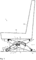
- a vehicle seat 1 is shown according to a particularly preferred embodiment, wherein the vehicle seat 1 has a seat top 2 and a seat bottom 3, wherein the seat top 2, a seat part 32 and a backrest 33 may be arranged.
- the seat bottom 3, however, is preferably connected to a body floor 34 or the like.
- the seat upper part 2 and the seat bottom 3 are further connected to each other by means of a scissors-type frame 4, the scissors-type frame 4 having at least one first scissor arm 6 and at least one second scissor arm 7, wherein the first scissor arm 6 and the second scissor arm 7 by means of a common axis of rotation 8 are rotatably connected.
- the first scissor arm 6 is in particular rotatably connected by means of a fixed bearing 29 with the seat upper part 2, whereas the second scissor arm 7 is connected in particular rotatably by means of a fixed bearing 29 with the seat bottom 3.
- Each scissor arm also has in each case a movable bearing 28, which is connected to the respective other vehicle seat part, for example, for the first scissor arm 6, the floating bearing is connected to the seat bottom 3, in particular slidably connected.
- a first end 9 of the damper 5 is connected to the first scissor arm 6 and a second end 10 of the damper 5 is rotatably connected on the one hand to a first lever element 11 and on the other hand to a second lever element 12, wherein in addition the first lever element 11 to the first scissor arm. 6 and the second lever member 12 is connected to the second scissor arm 7.
- the first end 9 of the damper 5 is arranged in the area of the movable bearing 28, that is to say at a first end 35 of the first scissor arm 6.
- the second end 10 of the damper 5 is forcibly guided by means of the first lever element 11 and the second lever element 12. This makes it possible to vary the distance of the first end 9 of the damper 5 to the second end 10 of the damper, in particular in this case a piston rod 36 of the damper 5 is displaced from or into a damper housing 37.
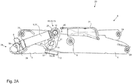
- FIGS. 2A and 2 B show the vehicle seat 1 in a first state 20, ie in a fully compressed state, the FIGS. 3A and 3B the vehicle seat 1 in a third state 22, ie in the state of normal operation, in particular without or with little force, and the FIGS. 4A and 4B the vehicle seat 1 in a second state 21, so a completely rebounded state.
- the first lever member 11 is rotatably connected by a first axis of rotation 17 with the first scissor arm 6, and the second lever member 12 rotatably connected by a second axis of rotation 18 with the second scissor arm 7, and the second end 10 of the damper 5 by means of a third axis of rotation 19 with the first lever member 11 and the second lever member 12.
- the length 38 of the piston rod 36 is indicated as the length of a fourth axis of rotation 39, by means of which the first end 9 of the damper is rotatably connected to the first scissor arm 6, to the Damper housing 37.
- the lever elements 11, 12 are connected only via the respective axes of rotation 17, 18 with the corresponding scissor arms 6, 7. This means that the lever elements 11, 12 are connected directly to the scissor arms 6, 7 by means of the axes of rotation 17, 18.
- FIGS. 2A and 2 B show the vehicle seat in the first state 20, in which the scissors-type frame 4 is completely or maximum springed.
- the first lever element 11 and the second lever element 12 are arranged at an angle 25.
- the angle 25 between a first connecting line 23 which extends between the first axis of rotation 17 and the third axis of rotation 19, and a second connecting line 24 which extends between the second axis of rotation 18 and the third axis of rotation 19 is included.
- this is in the case of the first state 20 to an acute angle 25.
- a distance of the first axis of rotation 17 to the third axis of rotation 19 is greater than a distance of the second axis of rotation 18 to the third axis of rotation 19, whereby a kind of initial condition for the Forced operation of the second end 10 of the damper 5 is given. If the angle 25 would be 0 °, then initially no specific direction of rotation of the second end 10 of the damper 5 would be predetermined. By such a configuration, however, a direction of rotation of the second end 10 is determined in this case, starting in the present case, starting from the first state 20 in initially the third state 22 in the direction of the arrow 40, which indicates the direction of rotation 40. By this direction of rotation 40, in the present case a rotation to the right in the drawing, the second end 10 of the damper 5 moves toward the common axis of rotation 8.
- FIG. 2B shows the subject of the FIG. 2A in a perspective view again. More particularly, two pairs of scissors 41 are shown, each pair of scissors having a first scissor arm 6 and a second scissor arm 7. Likewise, the corresponding lever elements 11, 12 are arranged on each scissor arm 6, 7.
- the entire device is formed symmetrically with respect to a plane E, which is spanned by a height direction H and a longitudinal direction L of the vehicle seat.
- the plane E may partially comprise the damper 5, that is, the damper 5 is arranged so that it is symmetrical to itself.
- FIGS. 3A and 3B show the vehicle seat 1 in the second state 21, that is, the vehicle seat 1 in the normal operating state.
- the length 38 of the piston rod has significantly extended after the damper has performed damping work.
- the second end 10 of the damper 5 has been moved in the direction of the common axis of rotation 8 due to the positive guidance by the first lever element 11 and the second lever element 12.
- the damper 5 is not or only slightly moved. This means that starting from the third state in normal operation, the damping force or the damping effect of the damper 5 is not or only slightly changed. This is referred to as comfort range for the driver, especially when a soft damper characteristic is set.
- the length 38 of the piston rod 36 changes considerably and as a result, the damping, in particular from a soft to a hard damper characteristic in order to avoid a possible end stop.
- the angle 25 between the first connecting line 23 and the second connecting line 24 for the third state 22 may be between 45 ° and 80 °, more preferably between 50 ° and 70 °, and most preferably 60 °.
- FIG. 3B shows in an analogous manner to FIG. 2B the object of FIG. 3A in a perspective view.
- FIGS. 4A and 4B show the vehicle seat in the second state 21, in which the vehicle seat 1 is deflected maximum.
- the length 38 of the piston rod 36 is again significantly reduced.
- the angle 25 between the first connecting line 23 and the second connecting line 24 is in this case essentially 180 °, that is to say the connecting lines 23, 24 are arranged on a common line. Further, it can be seen that the second end 10 has been moved away from the common axis of rotation 8 due to the positive guidance.
- FIGS. 2B and 3B show the FIG. 4B the object of FIG. 4A in a perspective view.
- FIG. 4B is the more detailed embodiment of the lever members 11, 12 can be seen.
- the first lever element 11 is here U-shaped at least in a direction perpendicular to the extension direction of the third axis of rotation 19 and includes a first leg 26 and a second leg 27, wherein the legs 26, 27 are connected to each other by means of a connecting element 42.
- the second leg 27 extends further in the direction of the first connecting line 23 than the first leg 26.
- the second lever element 12 in particular the second end 16 of the second lever element 12, is arranged between the first leg 26 and the second leg 27 in the extension direction of the third axis of rotation 19.
- the second lever element 12 may be plate-like.
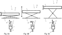
- FIGS. 5A, 5B and 5C show the various states of the vehicle seat 1 again in a schematic representation, in particular, a comparison between the deflection of the vehicle seat 1, in particular the seat shell 2 relative to the seat bottom 3, to the deflection of the damper 5 can be seen.
- the ratio of deflection of the vehicle seat 1 to the deflection of the damper 5, in particular the change in the length 38 of the piston rod 36 is less than or equal to 1 ( ⁇ 1).
- For the second state 21 shown in FIG. 5C is the ratio of deflection of the vehicle seat 1 to the deflection of the damper 5, in particular the change in the length 38 of the piston rod 36, also less than or equal to 1 ( ⁇ 1).
- the ratio of deflection of the vehicle seat 1 to the deflection of the damper 5, in particular the change in the length 38 of the piston rod 36, is greater than 1, in particular much greater than 1 (>> 1).
- a damper characteristic 43 can be achieved, as in the FIG. 6 shown.
- the damper effect changes only slightly, this area being indicated as a comfort area 44.
- the ratio of deflection of the vehicle seat 1 to the deflection of the damper 5 in particular the change in the length 38 of the piston rod 36, greater than 1, in particular much greater than 1 (>> 1). Due to the small deflection of the piston rod 36, the damper characteristic 43 changes in the comfort area 44 only slightly or not at all.
- the regions of the damper characteristic 43 which have a ratio of less than or equal to 1, are assigned to the first state 20 and the second state 21, as also already explained.
- the regions with a ratio of ⁇ 1, ie the regions between the first state 20 and the third state 22 as well as the third state 22 and the second state 21, relate to deflections of the vehicle seat which require increased damping, but not yet in the critical region the end stops lie.
- the damper characteristic 43 increases significantly with a strong deflection of the seat cover 3 up or down in the first state 20 or second state 21, so that an end stop can be prevented or at least mitigated.
- the damper deflection changes little or not at all.
- lever members 11 and 12 can not be attached only to the swinging arms 6, 7. It can also be the combination of seat shell / swing arm or seat bottom / swing arm.
Landscapes
- Engineering & Computer Science (AREA)
- Aviation & Aerospace Engineering (AREA)
- Transportation (AREA)
- Mechanical Engineering (AREA)
- Seats For Vehicles (AREA)
Applications Claiming Priority (1)
| Application Number | Priority Date | Filing Date | Title |
|---|---|---|---|
| DE102017115347.0A DE102017115347B4 (de) | 2017-07-10 | 2017-07-10 | Fahrzeugsitz mit einstellbarem Dämpfer und Nutzfahrzeug |
Publications (2)
| Publication Number | Publication Date |
|---|---|
| EP3428009A1 true EP3428009A1 (fr) | 2019-01-16 |
| EP3428009B1 EP3428009B1 (fr) | 2020-01-01 |
Family
ID=62846053
Family Applications (1)
| Application Number | Title | Priority Date | Filing Date |
|---|---|---|---|
| EP18181430.2A Active EP3428009B1 (fr) | 2017-07-10 | 2018-07-03 | Siège de véhicule doté d'un amortisseur réglable |
Country Status (3)
| Country | Link |
|---|---|
| US (1) | US10654381B2 (fr) |
| EP (1) | EP3428009B1 (fr) |
| DE (1) | DE102017115347B4 (fr) |
Cited By (6)
| Publication number | Priority date | Publication date | Assignee | Title |
|---|---|---|---|---|
| CN112046358A (zh) * | 2020-10-24 | 2020-12-08 | 浙江龙生汽车部件科技有限公司 | 汽车座椅气囊调节式减震装置及其高度调节方法 |
| DE102019134244A1 (de) * | 2019-12-13 | 2021-06-17 | Grammer Aktiengesellschaft | Fahrzeugsitz mit Scherengestellanordnung |
| US11279271B2 (en) | 2019-12-13 | 2022-03-22 | Grammer Ag | Vehicle seat having a suspension unit for cushioning rolling and vertical suspension movements |
| US11285846B2 (en) | 2019-12-13 | 2022-03-29 | Grammer Ag | Vehicle seat with scissor frame arrangement |
| US12005821B2 (en) | 2019-12-13 | 2024-06-11 | Grammer Ag | Cushioning rolling and vertical suspension movements |
| US12103446B2 (en) | 2019-12-13 | 2024-10-01 | Grammer Ag | Vehicle seat having a suspension unit for cushioning rolling and vertical suspension movements |
Families Citing this family (9)
| Publication number | Priority date | Publication date | Assignee | Title |
|---|---|---|---|---|
| CA2975551C (fr) * | 2015-02-20 | 2023-06-20 | The Braun Corporation | Ensemble de base de siege d'un vehicule |
| DK179239B9 (da) * | 2016-11-23 | 2018-04-30 | Global Fabtech Shanghai Company Ltd | Mekanisme til en sakselift eller et vippesystem, en sakselift og et vippesystem omfattende en sådan mekanisme og en kørestol med et sædehejs omfattende en sådan sakselift |
| US11618355B2 (en) * | 2018-06-15 | 2023-04-04 | Milsco, Llc | Low profile adjustable vehicle seat mount assembly |
| DE102018124507B4 (de) * | 2018-10-04 | 2020-06-18 | Grammer Ag | Fahrzeugsitz mit Nickfedereinheit |
| DE102018124512B4 (de) * | 2018-10-04 | 2020-09-03 | Grammer Ag | Fahrzeugsitz |
| CN110697052B (zh) * | 2019-09-28 | 2022-12-09 | 湖北航宇嘉泰飞机设备有限公司 | 一种异轴旋转剪切吸能航空座椅 |
| US11872916B2 (en) | 2020-09-24 | 2024-01-16 | Seats Incorporated | Damper system for suspension of vehicle seat |
| CN116118584B (zh) * | 2022-09-27 | 2024-04-19 | 常熟理工学院 | 一种基于多准则优化的磁流变悬挂座椅减振方法 |
| US12036903B1 (en) * | 2023-06-23 | 2024-07-16 | Ford Global Technologies, Llc | Vehicle seat with restraint system |
Citations (3)
| Publication number | Priority date | Publication date | Assignee | Title |
|---|---|---|---|---|
| DE102008023563B3 (de) * | 2008-05-09 | 2009-10-01 | Keiper Gmbh & Co. Kg | Fahrzeugsitz, insbesondere Nutzfahrzeugsitz |
| DE102009041811A1 (de) * | 2009-08-20 | 2011-04-07 | Grammer Ag | Fahrzeugsitz mit einem Dämpfungselement |
| DE102010048210A1 (de) * | 2010-10-13 | 2012-04-19 | Grammer Aktiengesellschaft | Fahrzeugsitz mit Fluidfeder |
Family Cites Families (12)
| Publication number | Priority date | Publication date | Assignee | Title |
|---|---|---|---|---|
| GB1407591A (en) * | 1971-11-27 | 1975-09-24 | Universal Oil Prod Co | Suspension systems for vehicle seats |
| US4448386A (en) * | 1981-12-01 | 1984-05-15 | Uop Inc. | Low profile resilient suspension for vehicle seat |
| US5222709A (en) * | 1990-04-13 | 1993-06-29 | Rosdon Engineering And Manufacturing Pty. Ltd. | Vehicle seat suspension unit |
| US5169112A (en) * | 1991-08-26 | 1992-12-08 | Milsco Manufacturing Company | Electronic suspension vehicle seat |
| DE4429405A1 (de) * | 1994-08-09 | 1996-02-15 | Isringhausen Geb | Schwingfähig abgestützter Fahrzeugsitz mit einer Neigungs- und/oder Höhenverstellung der Sitzfläche |
| US5957426A (en) * | 1997-04-10 | 1999-09-28 | Brodersen; Cole T. | Mechanical seat suspension with multiple position, lift-type height adjuster |
| US6550740B1 (en) | 2002-02-05 | 2003-04-22 | Peter J. Burer | Shock absorbing platform |
| DE102006017774B4 (de) * | 2006-04-15 | 2014-02-13 | Grammer Aktiengesellschaft | Fahrzeugsitz mit einem höhenverstellbaren Sitzgestell |
| DE102010026569B4 (de) * | 2009-07-28 | 2014-03-27 | Grammer Aktiengesellschaft | Regelungseinrichtung zur Reduzierung einer Schwingungsbewegung einer federkraftbeaufschlagten schwingenden Vorrichtung |
| US9527416B2 (en) * | 2012-05-21 | 2016-12-27 | Sears Manufacturing Co. | Vehicle seat scissors suspension with integrated stabilized isolator |
| US9782005B2 (en) * | 2014-07-25 | 2017-10-10 | Stryker Corporation | Medical support apparatus |
| DE102013021057B4 (de) | 2013-12-18 | 2017-06-08 | Grammer Ag | Druckminderer |
-
2017
- 2017-07-10 DE DE102017115347.0A patent/DE102017115347B4/de active Active
-
2018
- 2018-07-03 EP EP18181430.2A patent/EP3428009B1/fr active Active
- 2018-07-10 US US16/031,052 patent/US10654381B2/en active Active
Patent Citations (3)
| Publication number | Priority date | Publication date | Assignee | Title |
|---|---|---|---|---|
| DE102008023563B3 (de) * | 2008-05-09 | 2009-10-01 | Keiper Gmbh & Co. Kg | Fahrzeugsitz, insbesondere Nutzfahrzeugsitz |
| DE102009041811A1 (de) * | 2009-08-20 | 2011-04-07 | Grammer Ag | Fahrzeugsitz mit einem Dämpfungselement |
| DE102010048210A1 (de) * | 2010-10-13 | 2012-04-19 | Grammer Aktiengesellschaft | Fahrzeugsitz mit Fluidfeder |
Cited By (8)
| Publication number | Priority date | Publication date | Assignee | Title |
|---|---|---|---|---|
| DE102019134244A1 (de) * | 2019-12-13 | 2021-06-17 | Grammer Aktiengesellschaft | Fahrzeugsitz mit Scherengestellanordnung |
| US11279271B2 (en) | 2019-12-13 | 2022-03-22 | Grammer Ag | Vehicle seat having a suspension unit for cushioning rolling and vertical suspension movements |
| US11285846B2 (en) | 2019-12-13 | 2022-03-29 | Grammer Ag | Vehicle seat with scissor frame arrangement |
| US11685298B2 (en) | 2019-12-13 | 2023-06-27 | Grammer Ag | Vehicle seat with scissor frame arrangement |
| US12005821B2 (en) | 2019-12-13 | 2024-06-11 | Grammer Ag | Cushioning rolling and vertical suspension movements |
| DE102019134244B4 (de) | 2019-12-13 | 2024-08-01 | Grammer Aktiengesellschaft | Fahrzeugsitz mit Scherengestellanordnung |
| US12103446B2 (en) | 2019-12-13 | 2024-10-01 | Grammer Ag | Vehicle seat having a suspension unit for cushioning rolling and vertical suspension movements |
| CN112046358A (zh) * | 2020-10-24 | 2020-12-08 | 浙江龙生汽车部件科技有限公司 | 汽车座椅气囊调节式减震装置及其高度调节方法 |
Also Published As
| Publication number | Publication date |
|---|---|
| DE102017115347B4 (de) | 2020-07-02 |
| US10654381B2 (en) | 2020-05-19 |
| US20190009697A1 (en) | 2019-01-10 |
| DE102017115347A1 (de) | 2019-01-10 |
| EP3428009B1 (fr) | 2020-01-01 |
Similar Documents
| Publication | Publication Date | Title |
|---|---|---|
| EP3428009B1 (fr) | Siège de véhicule doté d'un amortisseur réglable | |
| DE102008056200B4 (de) | Scherengestell für einen Fahrzeugsitz, Fahrzeugsitz, insbesondere Kraftfahrzeugsitz, und Verfahren zum Herstellen eines Unterbaus eines Fahrzeugsitzes | |
| DE102017119698B4 (de) | Kindersicherheitssitz und Mechanismus zur Abstandsverstellung der Sitzwangen | |
| EP3181396B1 (fr) | Dispositif de vibration de véhicule | |
| EP2423039B1 (fr) | Dispositif d'amortissement de vibrations pour véhicule | |
| DE68906457T2 (de) | Aufhängungseinrichtung mit einem Nockenunterstützungselement. | |
| EP2818345B1 (fr) | Dispositif équipé d'un système de ressort | |
| EP3572275B1 (fr) | Siège de véhicule | |
| DE102010026569A1 (de) | Regelungseinrichtung zur Reduzierung einer Schwingungsbewegung einer federkraftbeaufschlagten schwingenden Vorrichtung | |
| DE102019122528A1 (de) | Abdeckungsvorrichtung für Fahrzeugsitze | |
| EP3569443A1 (fr) | Siège de véhicule doté d'un dispositif à ressort | |
| EP3835116A1 (fr) | Siège de véhicule pourvu de dispositif support à leviers croisés | |
| EP3763561B1 (fr) | Siège de véhicule pourvu de structure en ciseaux | |
| EP3181397B1 (fr) | Dispositif de vibration de véhicule | |
| DE102015117820B4 (de) | Vorrichtung zum Federn und/oder Dämpfen eines Oberteils gegenüber einem Unterteil und Fahrzeugsitz mit dieser Vorrichtung | |
| EP2223823B1 (fr) | Dispositif de suspension pour sièges de véhicule ainsi que suspension de siège de véhicule | |
| EP3626520B1 (fr) | Dispositif de couverture pour sièges de véhicule | |
| EP3835121B1 (fr) | Siège de véhicule doté d'une unité de ressort permettant de faire ressort du mouvement de roulis et de ressort vertical | |
| EP0449165B1 (fr) | Aménagement de siège, en particulier pour véhicules automobiles | |
| DE102020110757B3 (de) | Fahrzeugsitz | |
| EP3335929A1 (fr) | Siège de véhicule doté de suspension | |
| DE102018112019B4 (de) | Fahrzeugsitz mit einer Dämpfungseinrichtung | |
| DE102012200550B4 (de) | Sitzanordnung mit einem verstellbaren Dämpfmechanismus |
Legal Events
| Date | Code | Title | Description |
|---|---|---|---|
| PUAI | Public reference made under article 153(3) epc to a published international application that has entered the european phase |
Free format text: ORIGINAL CODE: 0009012 |
|
| STAA | Information on the status of an ep patent application or granted ep patent |
Free format text: STATUS: THE APPLICATION HAS BEEN PUBLISHED |
|
| AK | Designated contracting states |
Kind code of ref document: A1 Designated state(s): AL AT BE BG CH CY CZ DE DK EE ES FI FR GB GR HR HU IE IS IT LI LT LU LV MC MK MT NL NO PL PT RO RS SE SI SK SM TR |
|
| AX | Request for extension of the european patent |
Extension state: BA ME |
|
| STAA | Information on the status of an ep patent application or granted ep patent |
Free format text: STATUS: REQUEST FOR EXAMINATION WAS MADE |
|
| 17P | Request for examination filed |
Effective date: 20190124 |
|
| RBV | Designated contracting states (corrected) |
Designated state(s): AL AT BE BG CH CY CZ DE DK EE ES FI FR GB GR HR HU IE IS IT LI LT LU LV MC MK MT NL NO PL PT RO RS SE SI SK SM TR |
|
| GRAP | Despatch of communication of intention to grant a patent |
Free format text: ORIGINAL CODE: EPIDOSNIGR1 |
|
| RIC1 | Information provided on ipc code assigned before grant |
Ipc: B60N 2/52 20060101ALI20190626BHEP Ipc: B60N 2/50 20060101AFI20190626BHEP |
|
| STAA | Information on the status of an ep patent application or granted ep patent |
Free format text: STATUS: GRANT OF PATENT IS INTENDED |
|
| INTG | Intention to grant announced |
Effective date: 20190801 |
|
| GRAS | Grant fee paid |
Free format text: ORIGINAL CODE: EPIDOSNIGR3 |
|
| GRAA | (expected) grant |
Free format text: ORIGINAL CODE: 0009210 |
|
| STAA | Information on the status of an ep patent application or granted ep patent |
Free format text: STATUS: THE PATENT HAS BEEN GRANTED |
|
| AK | Designated contracting states |
Kind code of ref document: B1 Designated state(s): AL AT BE BG CH CY CZ DE DK EE ES FI FR GB GR HR HU IE IS IT LI LT LU LV MC MK MT NL NO PL PT RO RS SE SI SK SM TR |
|
| REG | Reference to a national code |
Ref country code: GB Ref legal event code: FG4D Free format text: NOT ENGLISH |
|
| REG | Reference to a national code |
Ref country code: CH Ref legal event code: EP Ref country code: AT Ref legal event code: REF Ref document number: 1219386 Country of ref document: AT Kind code of ref document: T Effective date: 20200115 |
|
| REG | Reference to a national code |
Ref country code: DE Ref legal event code: R096 Ref document number: 502018000588 Country of ref document: DE |
|
| REG | Reference to a national code |
Ref country code: IE Ref legal event code: FG4D Free format text: LANGUAGE OF EP DOCUMENT: GERMAN |
|
| REG | Reference to a national code |
Ref country code: NL Ref legal event code: MP Effective date: 20200101 |
|
| REG | Reference to a national code |
Ref country code: LT Ref legal event code: MG4D |
|
| PG25 | Lapsed in a contracting state [announced via postgrant information from national office to epo] |
Ref country code: NO Free format text: LAPSE BECAUSE OF FAILURE TO SUBMIT A TRANSLATION OF THE DESCRIPTION OR TO PAY THE FEE WITHIN THE PRESCRIBED TIME-LIMIT Effective date: 20200401 Ref country code: FI Free format text: LAPSE BECAUSE OF FAILURE TO SUBMIT A TRANSLATION OF THE DESCRIPTION OR TO PAY THE FEE WITHIN THE PRESCRIBED TIME-LIMIT Effective date: 20200101 Ref country code: NL Free format text: LAPSE BECAUSE OF FAILURE TO SUBMIT A TRANSLATION OF THE DESCRIPTION OR TO PAY THE FEE WITHIN THE PRESCRIBED TIME-LIMIT Effective date: 20200101 Ref country code: RS Free format text: LAPSE BECAUSE OF FAILURE TO SUBMIT A TRANSLATION OF THE DESCRIPTION OR TO PAY THE FEE WITHIN THE PRESCRIBED TIME-LIMIT Effective date: 20200101 Ref country code: LT Free format text: LAPSE BECAUSE OF FAILURE TO SUBMIT A TRANSLATION OF THE DESCRIPTION OR TO PAY THE FEE WITHIN THE PRESCRIBED TIME-LIMIT Effective date: 20200101 Ref country code: CZ Free format text: LAPSE BECAUSE OF FAILURE TO SUBMIT A TRANSLATION OF THE DESCRIPTION OR TO PAY THE FEE WITHIN THE PRESCRIBED TIME-LIMIT Effective date: 20200101 Ref country code: PT Free format text: LAPSE BECAUSE OF FAILURE TO SUBMIT A TRANSLATION OF THE DESCRIPTION OR TO PAY THE FEE WITHIN THE PRESCRIBED TIME-LIMIT Effective date: 20200527 |
|
| PG25 | Lapsed in a contracting state [announced via postgrant information from national office to epo] |
Ref country code: IS Free format text: LAPSE BECAUSE OF FAILURE TO SUBMIT A TRANSLATION OF THE DESCRIPTION OR TO PAY THE FEE WITHIN THE PRESCRIBED TIME-LIMIT Effective date: 20200501 Ref country code: BG Free format text: LAPSE BECAUSE OF FAILURE TO SUBMIT A TRANSLATION OF THE DESCRIPTION OR TO PAY THE FEE WITHIN THE PRESCRIBED TIME-LIMIT Effective date: 20200401 Ref country code: GR Free format text: LAPSE BECAUSE OF FAILURE TO SUBMIT A TRANSLATION OF THE DESCRIPTION OR TO PAY THE FEE WITHIN THE PRESCRIBED TIME-LIMIT Effective date: 20200402 Ref country code: SE Free format text: LAPSE BECAUSE OF FAILURE TO SUBMIT A TRANSLATION OF THE DESCRIPTION OR TO PAY THE FEE WITHIN THE PRESCRIBED TIME-LIMIT Effective date: 20200101 Ref country code: LV Free format text: LAPSE BECAUSE OF FAILURE TO SUBMIT A TRANSLATION OF THE DESCRIPTION OR TO PAY THE FEE WITHIN THE PRESCRIBED TIME-LIMIT Effective date: 20200101 Ref country code: HR Free format text: LAPSE BECAUSE OF FAILURE TO SUBMIT A TRANSLATION OF THE DESCRIPTION OR TO PAY THE FEE WITHIN THE PRESCRIBED TIME-LIMIT Effective date: 20200101 |
|
| REG | Reference to a national code |
Ref country code: DE Ref legal event code: R097 Ref document number: 502018000588 Country of ref document: DE |
|
| RAP2 | Party data changed (patent owner data changed or rights of a patent transferred) |
Owner name: GRAMMER AG |
|
| PG25 | Lapsed in a contracting state [announced via postgrant information from national office to epo] |
Ref country code: ES Free format text: LAPSE BECAUSE OF FAILURE TO SUBMIT A TRANSLATION OF THE DESCRIPTION OR TO PAY THE FEE WITHIN THE PRESCRIBED TIME-LIMIT Effective date: 20200101 Ref country code: SK Free format text: LAPSE BECAUSE OF FAILURE TO SUBMIT A TRANSLATION OF THE DESCRIPTION OR TO PAY THE FEE WITHIN THE PRESCRIBED TIME-LIMIT Effective date: 20200101 Ref country code: RO Free format text: LAPSE BECAUSE OF FAILURE TO SUBMIT A TRANSLATION OF THE DESCRIPTION OR TO PAY THE FEE WITHIN THE PRESCRIBED TIME-LIMIT Effective date: 20200101 Ref country code: DK Free format text: LAPSE BECAUSE OF FAILURE TO SUBMIT A TRANSLATION OF THE DESCRIPTION OR TO PAY THE FEE WITHIN THE PRESCRIBED TIME-LIMIT Effective date: 20200101 Ref country code: SM Free format text: LAPSE BECAUSE OF FAILURE TO SUBMIT A TRANSLATION OF THE DESCRIPTION OR TO PAY THE FEE WITHIN THE PRESCRIBED TIME-LIMIT Effective date: 20200101 Ref country code: EE Free format text: LAPSE BECAUSE OF FAILURE TO SUBMIT A TRANSLATION OF THE DESCRIPTION OR TO PAY THE FEE WITHIN THE PRESCRIBED TIME-LIMIT Effective date: 20200101 |
|
| PLBE | No opposition filed within time limit |
Free format text: ORIGINAL CODE: 0009261 |
|
| STAA | Information on the status of an ep patent application or granted ep patent |
Free format text: STATUS: NO OPPOSITION FILED WITHIN TIME LIMIT |
|
| 26N | No opposition filed |
Effective date: 20201002 |
|
| PG25 | Lapsed in a contracting state [announced via postgrant information from national office to epo] |
Ref country code: PL Free format text: LAPSE BECAUSE OF FAILURE TO SUBMIT A TRANSLATION OF THE DESCRIPTION OR TO PAY THE FEE WITHIN THE PRESCRIBED TIME-LIMIT Effective date: 20200101 Ref country code: SI Free format text: LAPSE BECAUSE OF FAILURE TO SUBMIT A TRANSLATION OF THE DESCRIPTION OR TO PAY THE FEE WITHIN THE PRESCRIBED TIME-LIMIT Effective date: 20200101 Ref country code: MC Free format text: LAPSE BECAUSE OF FAILURE TO SUBMIT A TRANSLATION OF THE DESCRIPTION OR TO PAY THE FEE WITHIN THE PRESCRIBED TIME-LIMIT Effective date: 20200101 |
|
| REG | Reference to a national code |
Ref country code: BE Ref legal event code: MM Effective date: 20200731 |
|
| PG25 | Lapsed in a contracting state [announced via postgrant information from national office to epo] |
Ref country code: IE Free format text: LAPSE BECAUSE OF NON-PAYMENT OF DUE FEES Effective date: 20200703 Ref country code: LU Free format text: LAPSE BECAUSE OF NON-PAYMENT OF DUE FEES Effective date: 20200703 |
|
| PG25 | Lapsed in a contracting state [announced via postgrant information from national office to epo] |
Ref country code: BE Free format text: LAPSE BECAUSE OF NON-PAYMENT OF DUE FEES Effective date: 20200731 |
|
| REG | Reference to a national code |
Ref country code: CH Ref legal event code: PL |
|
| PG25 | Lapsed in a contracting state [announced via postgrant information from national office to epo] |
Ref country code: LI Free format text: LAPSE BECAUSE OF NON-PAYMENT OF DUE FEES Effective date: 20210731 Ref country code: CH Free format text: LAPSE BECAUSE OF NON-PAYMENT OF DUE FEES Effective date: 20210731 |
|
| PG25 | Lapsed in a contracting state [announced via postgrant information from national office to epo] |
Ref country code: TR Free format text: LAPSE BECAUSE OF FAILURE TO SUBMIT A TRANSLATION OF THE DESCRIPTION OR TO PAY THE FEE WITHIN THE PRESCRIBED TIME-LIMIT Effective date: 20200101 Ref country code: MT Free format text: LAPSE BECAUSE OF FAILURE TO SUBMIT A TRANSLATION OF THE DESCRIPTION OR TO PAY THE FEE WITHIN THE PRESCRIBED TIME-LIMIT Effective date: 20200101 Ref country code: CY Free format text: LAPSE BECAUSE OF FAILURE TO SUBMIT A TRANSLATION OF THE DESCRIPTION OR TO PAY THE FEE WITHIN THE PRESCRIBED TIME-LIMIT Effective date: 20200101 |
|
| PG25 | Lapsed in a contracting state [announced via postgrant information from national office to epo] |
Ref country code: MK Free format text: LAPSE BECAUSE OF FAILURE TO SUBMIT A TRANSLATION OF THE DESCRIPTION OR TO PAY THE FEE WITHIN THE PRESCRIBED TIME-LIMIT Effective date: 20200101 Ref country code: AL Free format text: LAPSE BECAUSE OF FAILURE TO SUBMIT A TRANSLATION OF THE DESCRIPTION OR TO PAY THE FEE WITHIN THE PRESCRIBED TIME-LIMIT Effective date: 20200101 |
|
| GBPC | Gb: european patent ceased through non-payment of renewal fee |
Effective date: 20220703 |
|
| PG25 | Lapsed in a contracting state [announced via postgrant information from national office to epo] |
Ref country code: GB Free format text: LAPSE BECAUSE OF NON-PAYMENT OF DUE FEES Effective date: 20220703 |
|
| REG | Reference to a national code |
Ref country code: AT Ref legal event code: MM01 Ref document number: 1219386 Country of ref document: AT Kind code of ref document: T Effective date: 20230703 |
|
| PG25 | Lapsed in a contracting state [announced via postgrant information from national office to epo] |
Ref country code: AT Free format text: LAPSE BECAUSE OF NON-PAYMENT OF DUE FEES Effective date: 20230703 |
|
| PG25 | Lapsed in a contracting state [announced via postgrant information from national office to epo] |
Ref country code: AT Free format text: LAPSE BECAUSE OF NON-PAYMENT OF DUE FEES Effective date: 20230703 |
|
| PGFP | Annual fee paid to national office [announced via postgrant information from national office to epo] |
Ref country code: DE Payment date: 20250722 Year of fee payment: 8 |
|
| PGFP | Annual fee paid to national office [announced via postgrant information from national office to epo] |
Ref country code: IT Payment date: 20250731 Year of fee payment: 8 |
|
| PGFP | Annual fee paid to national office [announced via postgrant information from national office to epo] |
Ref country code: FR Payment date: 20250723 Year of fee payment: 8 |
|
| PGFP | Annual fee paid to national office [announced via postgrant information from national office to epo] |
Ref country code: AT Payment date: 20260410 Year of fee payment: 5 |