EP3428070B1 - Staudruckturbinenrotorblätter - Google Patents
Staudruckturbinenrotorblätter Download PDFInfo
- Publication number
- EP3428070B1 EP3428070B1 EP18183641.2A EP18183641A EP3428070B1 EP 3428070 B1 EP3428070 B1 EP 3428070B1 EP 18183641 A EP18183641 A EP 18183641A EP 3428070 B1 EP3428070 B1 EP 3428070B1
- Authority
- EP
- European Patent Office
- Prior art keywords
- rat
- blade
- support structures
- hub
- turbine
- Prior art date
- Legal status (The legal status is an assumption and is not a legal conclusion. Google has not performed a legal analysis and makes no representation as to the accuracy of the status listed.)
- Active
Links
Images

Classifications
-
- F—MECHANICAL ENGINEERING; LIGHTING; HEATING; WEAPONS; BLASTING
- F03—MACHINES OR ENGINES FOR LIQUIDS; WIND, SPRING, OR WEIGHT MOTORS; PRODUCING MECHANICAL POWER OR A REACTIVE PROPULSIVE THRUST, NOT OTHERWISE PROVIDED FOR
- F03D—WIND MOTORS
- F03D1/00—Wind motors with rotation axis substantially parallel to the air flow entering the rotor
- F03D1/06—Rotors
- F03D1/065—Rotors characterised by their construction elements
- F03D1/0675—Rotors characterised by their construction elements of the blades
-
- B—PERFORMING OPERATIONS; TRANSPORTING
- B33—ADDITIVE MANUFACTURING TECHNOLOGY
- B33Y—ADDITIVE MANUFACTURING, i.e. MANUFACTURING OF THREE-DIMENSIONAL [3D] OBJECTS BY ADDITIVE DEPOSITION, ADDITIVE AGGLOMERATION OR ADDITIVE LAYERING, e.g. BY 3D PRINTING, STEREOLITHOGRAPHY OR SELECTIVE LASER SINTERING
- B33Y80/00—Products made by additive manufacturing
-
- B—PERFORMING OPERATIONS; TRANSPORTING
- B64—AIRCRAFT; AVIATION; COSMONAUTICS
- B64D—EQUIPMENT FOR FITTING IN OR TO AIRCRAFT; FLIGHT SUITS; PARACHUTES; ARRANGEMENT OR MOUNTING OF POWER PLANTS OR PROPULSION TRANSMISSIONS IN AIRCRAFT
- B64D41/00—Power installations for auxiliary purposes
- B64D41/007—Ram air turbines
-
- F—MECHANICAL ENGINEERING; LIGHTING; HEATING; WEAPONS; BLASTING
- F03—MACHINES OR ENGINES FOR LIQUIDS; WIND, SPRING, OR WEIGHT MOTORS; PRODUCING MECHANICAL POWER OR A REACTIVE PROPULSIVE THRUST, NOT OTHERWISE PROVIDED FOR
- F03D—WIND MOTORS
- F03D9/00—Adaptations of wind motors for special use; Combinations of wind motors with apparatus driven thereby; Wind motors specially adapted for installation in particular locations
- F03D9/30—Wind motors specially adapted for installation in particular locations
- F03D9/32—Wind motors specially adapted for installation in particular locations on moving objects, e.g. vehicles
-
- F—MECHANICAL ENGINEERING; LIGHTING; HEATING; WEAPONS; BLASTING
- F01—MACHINES OR ENGINES IN GENERAL; ENGINE PLANTS IN GENERAL; STEAM ENGINES
- F01D—NON-POSITIVE DISPLACEMENT MACHINES OR ENGINES, e.g. STEAM TURBINES
- F01D5/00—Blades; Blade-carrying members; Heating, heat-insulating, cooling or antivibration means on the blades or the members
- F01D5/12—Blades
- F01D5/14—Form or construction
- F01D5/147—Construction, i.e. structural features, e.g. of weight-saving hollow blades
-
- F—MECHANICAL ENGINEERING; LIGHTING; HEATING; WEAPONS; BLASTING
- F01—MACHINES OR ENGINES IN GENERAL; ENGINE PLANTS IN GENERAL; STEAM ENGINES
- F01D—NON-POSITIVE DISPLACEMENT MACHINES OR ENGINES, e.g. STEAM TURBINES
- F01D5/00—Blades; Blade-carrying members; Heating, heat-insulating, cooling or antivibration means on the blades or the members
- F01D5/12—Blades
- F01D5/14—Form or construction
- F01D5/18—Hollow blades, i.e. blades with cooling or heating channels or cavities; Heating, heat-insulating or cooling means on blades
-
- F—MECHANICAL ENGINEERING; LIGHTING; HEATING; WEAPONS; BLASTING
- F05—INDEXING SCHEMES RELATING TO ENGINES OR PUMPS IN VARIOUS SUBCLASSES OF CLASSES F01-F04
- F05B—INDEXING SCHEME RELATING TO WIND, SPRING, WEIGHT, INERTIA OR LIKE MOTORS, TO MACHINES OR ENGINES FOR LIQUIDS COVERED BY SUBCLASSES F03B, F03D AND F03G
- F05B2220/00—Application
- F05B2220/30—Application in turbines
- F05B2220/31—Application in turbines in ram-air turbines ("RATS")
-
- F—MECHANICAL ENGINEERING; LIGHTING; HEATING; WEAPONS; BLASTING
- F05—INDEXING SCHEMES RELATING TO ENGINES OR PUMPS IN VARIOUS SUBCLASSES OF CLASSES F01-F04
- F05B—INDEXING SCHEME RELATING TO WIND, SPRING, WEIGHT, INERTIA OR LIKE MOTORS, TO MACHINES OR ENGINES FOR LIQUIDS COVERED BY SUBCLASSES F03B, F03D AND F03G
- F05B2230/00—Manufacture
- F05B2230/30—Manufacture with deposition of material
-
- F—MECHANICAL ENGINEERING; LIGHTING; HEATING; WEAPONS; BLASTING
- F05—INDEXING SCHEMES RELATING TO ENGINES OR PUMPS IN VARIOUS SUBCLASSES OF CLASSES F01-F04
- F05B—INDEXING SCHEME RELATING TO WIND, SPRING, WEIGHT, INERTIA OR LIKE MOTORS, TO MACHINES OR ENGINES FOR LIQUIDS COVERED BY SUBCLASSES F03B, F03D AND F03G
- F05B2230/00—Manufacture
- F05B2230/50—Building or constructing in particular ways
-
- F—MECHANICAL ENGINEERING; LIGHTING; HEATING; WEAPONS; BLASTING
- F05—INDEXING SCHEMES RELATING TO ENGINES OR PUMPS IN VARIOUS SUBCLASSES OF CLASSES F01-F04
- F05B—INDEXING SCHEME RELATING TO WIND, SPRING, WEIGHT, INERTIA OR LIKE MOTORS, TO MACHINES OR ENGINES FOR LIQUIDS COVERED BY SUBCLASSES F03B, F03D AND F03G
- F05B2240/00—Components
- F05B2240/20—Rotors
- F05B2240/30—Characteristics of rotor blades, i.e. of any element transforming dynamic fluid energy to or from rotational energy and being attached to a rotor
- F05B2240/301—Cross-section characteristics
-
- F—MECHANICAL ENGINEERING; LIGHTING; HEATING; WEAPONS; BLASTING
- F05—INDEXING SCHEMES RELATING TO ENGINES OR PUMPS IN VARIOUS SUBCLASSES OF CLASSES F01-F04
- F05B—INDEXING SCHEME RELATING TO WIND, SPRING, WEIGHT, INERTIA OR LIKE MOTORS, TO MACHINES OR ENGINES FOR LIQUIDS COVERED BY SUBCLASSES F03B, F03D AND F03G
- F05B2250/00—Geometry
- F05B2250/20—Geometry three-dimensional
- F05B2250/28—Geometry three-dimensional patterned
- F05B2250/283—Honeycomb
-
- F—MECHANICAL ENGINEERING; LIGHTING; HEATING; WEAPONS; BLASTING
- F05—INDEXING SCHEMES RELATING TO ENGINES OR PUMPS IN VARIOUS SUBCLASSES OF CLASSES F01-F04
- F05D—INDEXING SCHEME FOR ASPECTS RELATING TO NON-POSITIVE-DISPLACEMENT MACHINES OR ENGINES, GAS-TURBINES OR JET-PROPULSION PLANTS
- F05D2220/00—Application
- F05D2220/30—Application in turbines
- F05D2220/34—Application in turbines in ram-air turbines ("RATS")
-
- Y—GENERAL TAGGING OF NEW TECHNOLOGICAL DEVELOPMENTS; GENERAL TAGGING OF CROSS-SECTIONAL TECHNOLOGIES SPANNING OVER SEVERAL SECTIONS OF THE IPC; TECHNICAL SUBJECTS COVERED BY FORMER USPC CROSS-REFERENCE ART COLLECTIONS [XRACs] AND DIGESTS
- Y02—TECHNOLOGIES OR APPLICATIONS FOR MITIGATION OR ADAPTATION AGAINST CLIMATE CHANGE
- Y02E—REDUCTION OF GREENHOUSE GAS [GHG] EMISSIONS, RELATED TO ENERGY GENERATION, TRANSMISSION OR DISTRIBUTION
- Y02E10/00—Energy generation through renewable energy sources
- Y02E10/70—Wind energy
- Y02E10/72—Wind turbines with rotation axis in wind direction
-
- Y—GENERAL TAGGING OF NEW TECHNOLOGICAL DEVELOPMENTS; GENERAL TAGGING OF CROSS-SECTIONAL TECHNOLOGIES SPANNING OVER SEVERAL SECTIONS OF THE IPC; TECHNICAL SUBJECTS COVERED BY FORMER USPC CROSS-REFERENCE ART COLLECTIONS [XRACs] AND DIGESTS
- Y02—TECHNOLOGIES OR APPLICATIONS FOR MITIGATION OR ADAPTATION AGAINST CLIMATE CHANGE
- Y02E—REDUCTION OF GREENHOUSE GAS [GHG] EMISSIONS, RELATED TO ENERGY GENERATION, TRANSMISSION OR DISTRIBUTION
- Y02E10/00—Energy generation through renewable energy sources
- Y02E10/70—Wind energy
- Y02E10/728—Onshore wind turbines
-
- Y—GENERAL TAGGING OF NEW TECHNOLOGICAL DEVELOPMENTS; GENERAL TAGGING OF CROSS-SECTIONAL TECHNOLOGIES SPANNING OVER SEVERAL SECTIONS OF THE IPC; TECHNICAL SUBJECTS COVERED BY FORMER USPC CROSS-REFERENCE ART COLLECTIONS [XRACs] AND DIGESTS
- Y02—TECHNOLOGIES OR APPLICATIONS FOR MITIGATION OR ADAPTATION AGAINST CLIMATE CHANGE
- Y02P—CLIMATE CHANGE MITIGATION TECHNOLOGIES IN THE PRODUCTION OR PROCESSING OF GOODS
- Y02P70/00—Climate change mitigation technologies in the production process for final industrial or consumer products
- Y02P70/50—Manufacturing or production processes characterised by the final manufactured product
-
- Y—GENERAL TAGGING OF NEW TECHNOLOGICAL DEVELOPMENTS; GENERAL TAGGING OF CROSS-SECTIONAL TECHNOLOGIES SPANNING OVER SEVERAL SECTIONS OF THE IPC; TECHNICAL SUBJECTS COVERED BY FORMER USPC CROSS-REFERENCE ART COLLECTIONS [XRACs] AND DIGESTS
- Y02—TECHNOLOGIES OR APPLICATIONS FOR MITIGATION OR ADAPTATION AGAINST CLIMATE CHANGE
- Y02P—CLIMATE CHANGE MITIGATION TECHNOLOGIES IN THE PRODUCTION OR PROCESSING OF GOODS
- Y02P80/00—Climate change mitigation technologies for sector-wide applications
- Y02P80/10—Efficient use of energy, e.g. using compressed air or pressurized fluid as energy carrier
Definitions
- the following description relates to ram air turbine (RAT) blades and, more specifically, to 3D printed RAT blades with honeycomb cores.
- RAT ram air turbine
- a RAT is an aircraft-mounted device that is used to extract power from an airstream for emergency or other use.
- a RAT typically includes a rotating turbine mounted to a strut, a driveshaft/driveline potentially including a gearbox, a power generation device that is typically an electrical generator, a hydraulic pump or both and ancillary equipment such as a stow abort mechanism, bonding straps, a turbine release cable, a proximity sensor, etc.
- Certain types of RATs may be mounted to in-flight refueling or weapons pods for military use.
- a RAT blade includes an airfoil and a shank which serves as a transition from an exposed airfoil section to turbine hub internals.
- the shank is used to retain the blade against centrifugal forces and to control the blade angle.
- a RAT blade is traditionally manufactured from solid aluminum and can be heavy especially in large blade RAT designs. This heaviness impacts RAT turbine design as explained below.
- each of the blade sections As an RAT turbine spins, the masses of each of the blade sections generate centrifugal force towards the RAT turbine centerline that is required to provide the required centripetal acceleration. All sections of the blade and particularly lower sections of the blade (i.e., those closer to the hub) must have adequate strength to ensure structural integrity of the blade itself under such centrifugal loads. This drives a need for more blade material and drives increased blade mass. In other words, the blade gains mass just to support its own mass under centrifugal loads. The mass of an entire RAT blade, again acted upon by centrifugal loads, must be reacted by the turbine hub and blade bearings. Higher blade mass drives increased hub mass as well as increased capacity blade bearings, which drives increased mass of the turbine itself.
- Blade mass also results in a proportional (to mass and to the square of speed) centrifugal turning moment (CTM).
- CTM centrifugal turning moment
- This is a turning moment that acts about the blade's axis and tends to drive the blade towards fine pitch. Forces toward fine pitch increase with rotational speed and is counteractive to good governing behavior (a fine pitch blade angle extracts more power from the airstream than a coarse pitch blade, and tends to drive higher turbine speed, which if not counteracted could result in a runaway condition and eventual RAT failure).
- the blade CTM must be overcome by a large counterweight mass, packaged inside the hub.
- higher blade mass results in higher counterweight mass, which in turn drives higher turbine mass, a larger turbine hub, higher governing friction, and so on.
- US 4,834,616 relates to means and a method for securing a composite rotor blade.
- a ram air turbine includes a turbine assembly including blades and a hub to which the blades are connected, a generator or a pump and a drivetrain mechanically interposed between the turbine assembly and the generator or the pump.
- Each blade includes an exterior, airfoil-shaped structure defining an interior and support structures disposed within the interior which connect with an inner surface of the exterior, airfoil-shaped structure and which define hollow regions within the interior.
- At least one of the hub, the generator or the pump and the drivetrain are rated for operation with each blade.
- the exterior, airfoil-shaped structure is metallic, tapered with increasing radial distance from the hub and includes a leading edge, a trailing edge opposite the leading edge, a low-pressure surface extending from the leading edge to the trailing edge and a high-pressure surface extending from the leading edge to the trailing edge and opposite the low-pressure surface.
- the support structures include metallic materials.
- the support structures are provided in a honeycomb pattern.
- a pitch between proximal support structures varies with increasing radial distance from the hub.
- widths of the support structures varies with increasing radial distance from the hub such that the support structures are lightest at a tip of the blade.
- a ram air turbine (RAT) assembly comprising the ram air turbine is provided.
- the exterior, airfoil-shaped structure is metallic, tapered with increasing radial distance from the hub and includes a leading edge, a trailing edge opposite the leading edge, a low-pressure surface extending from the leading edge to the trailing edge and a high-pressure surface extending from the leading edge to the trailing edge and opposite the low-pressure surface.
- the support structures include metallic materials.
- a non-claimed method of forming a blade for a ram air turbine (RAT) assembly includes the blade and at least another blade and a hub to which the blades are connected, a generator or a pump and a drivetrain mechanically interposed between the RAT assembly and the generator or the pump.
- RAT ram air turbine
- the method of forming the blade include compiling external specifications describing an exterior, airfoil-shape of the blade, loading the external specifications into an additive manufacturing device, instructing the additive manufacturing device to form a structure having the exterior, airfoil-shape such that the structure defines an interior and instructing the additive manufacturing device to dispose support structures within the interior such that the support structures connect with an inner surface of the structure and such that the support structures define hollow regions within the interior.
- the method includes re-designing at least one of the hub, the generator or the pump and the drivetrain in accordance with the structure and the support structures formed by the additive manufacturing device.
- the instructing of the additive manufacturing device to form the structure includes instructing the additive manufacturing device to form the structure with metallic materials, instructing the additive manufacturing device to taper the structure with increasing radial distance from the hub and instructing the additive manufacturing device to form the structure to include a leading edge, a trailing edge opposite the leading edge, a low-pressure surface extending from the leading edge to the trailing edge and a high-pressure surface extending from the leading edge to the trailing edge and opposite the low-pressure surface.
- the method further includes instructing the additive manufacturing device to form the support structures with metallic materials.
- the method further includes instructing the additive manufacturing device to form the support structures in a honeycomb pattern.
- the method further includes instructing the additive manufacturing device to vary a pitch between proximal support structures with increasing radial distance from the hub.
- the method further includes instructing the additive manufacturing device to vary widths of support structures with increasing radial distance from the hub.
- Blade resonant response is also related to blade mass.
- a lighter blade, or even a 'tuned' blade, with mass and stiffness/strength located in specific/desired areas could help to avoid flutter responses of the blade design by operating below the blade natural frequency, or by tuning the blade design (stiffness, mass distribution) to ensure that the RAT governing speed is between blade natural frequencies.
- RAT turbine blade mass drives increased RAT turbine mass, increased RAT hub diameter, degrades governing performance and degrades natural frequency margins.
- RAT turbine blade mass is a very significant driver to turbine sizing and mass.
- Reduced mass RAT turbine blade designs therefore, could provide very significant benefits including for example RAT designs which are smaller, lighter, have reduced governing speed ranges and improved critical speed margins.
- a RAT blade is provided with reduced mass.
- the mass reductions are achieved through a change in design approach from a solid material structure to a 3D printed hollow core and skin configuration.
- the core could be a honeycomb or similar structure which could be optimized to greater or lesser density (i.e., honeycomb size and spacing), and may include ribs of varying thicknesses.
- honeycomb size and spacing i.e., honeycomb size and spacing
- ribs of varying thicknesses.
- a density and strength of the RAT blade could be tailored to specific design needs in different areas of the RAT blade for optimum results.
- the use of 3D printing provides for a way to manufacture the proposed complex RAT blade configuration with a seamless printed material construction and negates the need to manufacture a separate core structure to which a skin would need to be affixed.
- blade root/shank area could be printed as part of a single structure with the airfoil, or could be produced separately and attached to the airfoil (e.g., by welding or similar processes).
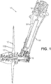
- the RAT 10 includes a turbine assembly 12, a strut 14, a generator or a pump 16 (hereinafter referred to as a generator 16) and a drivetrain (or driveline) 18 that includes a strut driveshaft 20.
- the turbine assembly 12 can include RAT turbine blades 120, a hub 121, a hub locking mechanism, suitable pitch or speed control mechanisms, a gearbox, etc.
- the strut 14 provides structural support of the RAT 10 and helps support the turbine assembly 12.
- the strut 14 has a hollow and generally cylindrical shape.
- the generator 16 is positioned at a proximal end of the strut opposite the turbine assembly 12.
- the generator 16 is merely one form of power conversion device that can be used with the RAT 10, and is shown merely by way of example and not limitation.
- a hydraulic pump can be used in place of or in addition to the generator 16 in further embodiments.
- the drivetrain 18 includes suitable shafts and gearing to provide a mechanical connection between the turbine assembly 12 and the generator 16, in order to transmit rotational energy (torque) to the generator 16.
- the strut driveshaft 20 is part of the drivetrain 18, and is positioned at least partially within the strut 14. The strut driveshaft 20 can directly engage the generator 16, and can engage suitable gearing that mates with the turbine assembly 12.
- the turbine is configured to have an operating range of approximately 3,800-5,000 RPM (or 63.33-83.33 Hz), with suitable gearing providing a gear ratio to operate the strut driveshaft 20 and the generator 16 at an operating range of approximately 8,000-12,000 RPM (133-200 Hz).
- the RAT 10 in the illustrated embodiment is configured to be selectively deployable from fuselage of the aircraft using suitable actuators (not shown). When deployed, the RAT 10 presents the turbine assembly 12 to airflow passing the aircraft, and can be used to generate desired forms of power using kinetic energy from rotation of components of the turbine assembly 12 produced by the passing airflow. The RAT 10 can be deployed in-flight to provide emergency or secondary power.
- each RAT turbine blade 120 includes an exterior, airfoil-shaped structure 201 and support structures 202.
- the exterior, airfoil-shaped structure 201 is formed to define an interior 203 that is partially hollow as will be described below and the support structures 202 are disposed within the interior 203.
- the support structures 202 connect with an inner surface 204 of the exterior, airfoil-shaped structure 201 and are formed to define hollow regions 205 within the interior 203.
- each RAT turbine blade 120 has a same external shape as a conventional RAT blade but is at least partially hollow inside.
- each RAT turbine blade 120 is lighter than the conventional version thereof. Therefore, since at least one of the hub 121, the generator 16 and the drivetrain 18 are rated for operation with each RAT turbine blade 120, at least one of the hub 121, the generator 16 and the drivetrain 18 can be re-designed in accordance with the external shape and weight of each RAT turbine blade 120.
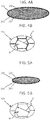
- the exterior, airfoil-shaped structure 201 is metallic, tapered with increasing radial distance from the hub 121 (see the tapering of FIG. 2 and the relative decrease in area of the cross-sections of FIGS. 3A , 4A and 4B ) and includes a leading edge 301, a trailing edge 302 that is opposite the leading edge 301, a low-pressure surface 303 that extends from the leading edge 301 to the trailing edge 302 and a high-pressure surface 304 that extends from the leading edge 301 to the trailing edge 302 and is opposite the low-pressure surface 303 (see FIG. 3A ).
- the support structures 202 may include or be formed of metallic materials and may be provided in a honeycomb pattern 305 (see FIG. 3B ). As shown in FIGS. 3B , 4B and 5B , a pitch P between proximal support structures 202 may vary with increasing radial distance from the hub 121 and widths W of the support structures 202 may also vary (dependently or independently from the varying pitch P) with increasing radial distance from the hub 121.
- the varying pitch P and the varying widths W allows the support structures 202 to be designed such that the support structures 202 are strongest at or proximate to the hub 121 where the most significant centrifugal forces are reacted to and such that the support structures 202 are lightest at or proximate to the tip 206 of each RAT turbine blade 120 so as to limit their contribution to the centrifugal forces.
- honeycomb pattern 305 is illustrated in FIGS. 3B , 4B and 5B as being oriented transversely with respect to radial distance from the hub 121, it is to be understood that this is not required and that the honeycomb pattern 305 or any other pattern of the support structures 202 may be oriented in any direction deemed appropriate to react to centrifugal forces.
- the honeycomb pattern 305 may be oriented in parallel with respect to radial distance from the hub 121.
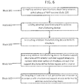
- each RAT turbine blade 120 includes compiling external specifications describing an exterior, airfoil-shape of the RAT turbine blade 120 which are already designed and understood (block 601).
- the method further includes loading the external specifications into an additive manufacturing device, such as a 3D printer that is capable of any one or more of several known 3D printing processes, such as direct metal laser sintering (DMLS) (block 602) and instructing the additive manufacturing device to form the structure 201 having the exterior, airfoil-shape such that the structure 201 defines the interior 203 (block 603).
- an additive manufacturing device such as a 3D printer that is capable of any one or more of several known 3D printing processes, such as direct metal laser sintering (DMLS)
- DMLS direct metal laser sintering
- the method includes instructing the additive manufacturing device to dispose the support structures 202 within the interior 203 such that the support structures 202 connect with the inner surface 204 of the structure 201 and such that the support structures 202 define the hollow regions 205 within the interior 203 (block 604).
- the method may further include re-designing at least one of the hub 121, the generator 16 and the drivetrain 18 in accordance with the structure 201 and the support structures 202 formed by the additive manufacturing device (block 605) and the instructing of the additive manufacturing device to form the structure 202 of block 603 may include instructing the additive manufacturing device to form the structure 202 with metallic materials, to taper the structure 202 with increasing radial distance from the hub 121 and to form the structure 202 to include the leading edge 301, the trailing edge 302, the low-pressure surface 303 and the high-pressure surface 304.
- the method may also include instructing the additive manufacturing device to form the support structures 202 with metallic materials, instructing the additive manufacturing device to form the support structures 202 in the honeycomb pattern 305, instructing the additive manufacturing device to vary the pitch P between proximal support structures 202 with increasing radial distance from the hub 121 and instructing the additive manufacturing device to independently vary the widths W of the support structures 202 with increasing radial distance from the hub 121.
- the use of the 3D printing enabled by the additive manufacturing device provides for the optional formation of complex shapes for at least some of the support structures 202.
- complex support structures 210 are illustrated as being proximate to the hub 121. These complex support structures 210 may include features such as three-dimensional overlapping and irregular curvatures and thus may only be formable in a reasonably simple and reproducible manner by way of 3D printing processes.
Landscapes
- Engineering & Computer Science (AREA)
- Chemical & Material Sciences (AREA)
- Life Sciences & Earth Sciences (AREA)
- Sustainable Development (AREA)
- Sustainable Energy (AREA)
- Aviation & Aerospace Engineering (AREA)
- Combustion & Propulsion (AREA)
- Mechanical Engineering (AREA)
- General Engineering & Computer Science (AREA)
- Manufacturing & Machinery (AREA)
- Materials Engineering (AREA)
- Power Engineering (AREA)
- Turbine Rotor Nozzle Sealing (AREA)
- Structures Of Non-Positive Displacement Pumps (AREA)
Claims (9)
- Stauluftturbine (ram air turbine - RAT), umfassend:eine Turbinenanordnung (12), die Laufschaufeln (120) und eine Nabe (121), mit der die Laufschaufeln verbunden sind, umfasst;einen Generator oder eine Pumpe (16); undeinen Antriebsstrang (18), der mechanisch zwischen der Turbinenanordnung (12) und dem Generator oder der Pumpe (16) zwischengeschaltet ist,wobei jede Laufschaufel (120) Folgendes umfasst:eine äußere, schaufelprofilförmige Struktur (201), die ein Inneres (203) definiert; undStützstrukturen (202), die innerhalb des Inneren (203) angeordnet sind, die sich mit einer Innenfläche (204) der äußeren, schaufelprofilförmigen Struktur (201) verbinden und die hohle Bereiche (205) innerhalb des Inneren (203) definieren;dadurch gekennzeichnet, dass die Stützstrukturen (202) in einem Wabenmuster bereitgestellt sind, wobei ein Abstand zwischen proximalen Stützstrukturen (202) mit zunehmender radialer Entfernung von der Nabe variiert und Breiten der Stützstrukturen (202) mit zunehmender radialer Entfernung von der Nabe variiert, so dass die Stützstrukturen an einer Spitze der Laufschaufel am leichtesten sind.
- RAT nach Anspruch 1, wobei mindestens eines aus der Nabe (121), dem Generator oder der Pumpe (16) und dem Antriebsstrang (18) für den Betrieb mit jeder Laufschaufel (120) ausgelegt sind.
- RAT nach den Ansprüchen 1 oder 2, wobei die äußere, schaufelprofilförmige Struktur (201) metallisch ist, sich mit zunehmender radialer Entfernung von der Nabe (121) verjüngt und Folgendes umfasst:eine Vorderkante (301);eine Hinterkante (302) gegenüber der Vorderkante (301);eine Niederdruckfläche (303), die sich von der Vorderkante (301) zur Hinterkante (302) erstreckt; undeine Hochdruckfläche (304), die sich von der Vorderkante (301) zur Hinterkante (302) und gegenüber der Niederdruckfläche (303) erstreckt.
- RAT nach einem der vorstehenden Ansprüche, wobei die Stützstrukturen (202) metallische Materialien umfassen.
- Stauluftturbinen(ram air turbine - RAT)-Anordnung, eine Stauluftturbine nach Anspruch 1 umfassend.
- RAT-Anordnung nach Anspruch 5, wobei die äußere, schaufelprofilförmige Struktur (201) metallisch ist.
- RAT-Anordnung nach den Ansprüchen 5 oder 6, wobei die äußere, schaufelprofilförmige Struktur (201) sich mit zunehmender radialer Entfernung von der Nabe (121) verjüngt.
- RAT-Anordnung nach einem der Ansprüche 5-7, wobei die äußere, schaufelprofilförmige Struktur (201) Folgendes umfasst:eine Vorderkante (301);eine Hinterkante (302) gegenüber der Vorderkante (301);eine Niederdruckfläche (303), die sich von der Vorderkante (301) zur Hinterkante (302) erstreckt; undeine Hochdruckfläche (304), die sich von der Vorderkante (301) zur Hinterkante (302) und gegenüber der Niederdruckfläche (303) erstreckt.
- RAT-Anordnung nach einem der Ansprüche 5-8, wobei die Stützstrukturen (202) metallische Materialien umfassen.
Applications Claiming Priority (1)
| Application Number | Priority Date | Filing Date | Title |
|---|---|---|---|
| US15/650,628 US10800542B2 (en) | 2017-07-14 | 2017-07-14 | Ram air turbine blades |
Publications (2)
| Publication Number | Publication Date |
|---|---|
| EP3428070A1 EP3428070A1 (de) | 2019-01-16 |
| EP3428070B1 true EP3428070B1 (de) | 2021-08-25 |
Family
ID=62975911
Family Applications (1)
| Application Number | Title | Priority Date | Filing Date |
|---|---|---|---|
| EP18183641.2A Active EP3428070B1 (de) | 2017-07-14 | 2018-07-16 | Staudruckturbinenrotorblätter |
Country Status (3)
| Country | Link |
|---|---|
| US (1) | US10800542B2 (de) |
| EP (1) | EP3428070B1 (de) |
| CA (1) | CA3011298A1 (de) |
Families Citing this family (3)
| Publication number | Priority date | Publication date | Assignee | Title |
|---|---|---|---|---|
| US11603212B1 (en) * | 2021-11-04 | 2023-03-14 | Hamilton Sundstrand Corporation | Strut with inner damper rod |
| CN115477000B (zh) * | 2022-09-21 | 2025-09-23 | 西安交通大学 | 一种基于voronoi的纤维增强复合材料3D打印机翼及其设计方法 |
| CN115387955B (zh) * | 2022-10-13 | 2023-04-07 | 新创碳谷集团有限公司 | 一种无芯材风电叶片叶尖部结构及成型方法 |
Family Cites Families (12)
| Publication number | Priority date | Publication date | Assignee | Title |
|---|---|---|---|---|
| GB2167500B (en) * | 1984-11-20 | 1988-05-18 | Rolls Royce | Rotor aerofoil blade containment |
| US4834616A (en) * | 1986-05-30 | 1989-05-30 | Sundstrand Corporation | Means and method for securing a composite rotor blade |
| US5314309A (en) * | 1990-05-25 | 1994-05-24 | Anthony Blakeley | Turbine blade with metallic attachment and method of making the same |
| US5725355A (en) * | 1996-12-10 | 1998-03-10 | General Electric Company | Adhesive bonded fan blade |
| WO2003093101A1 (en) | 2002-04-29 | 2003-11-13 | Rolls-Royce Naval Marine, Inc. | Propeller |
| GB0709838D0 (en) * | 2007-05-23 | 2007-07-04 | Rolls Royce Plc | A hollow blade and a method of manufacturing a hollow blade |
| US9188105B2 (en) * | 2011-04-19 | 2015-11-17 | Hamilton Sundstrand Corporation | Strut driveshaft for ram air turbine |
| US9121287B2 (en) * | 2012-09-12 | 2015-09-01 | United Technologies Corporation | Hollow fan blade with honeycomb filler |
| DE102012018871B4 (de) | 2012-09-25 | 2014-12-24 | Fraunhofer-Gesellschaft zur Förderung der angewandten Forschung e.V. | Strömungskörper und Verfahren zur Herstellung eines solchen |
| BE1022481B1 (fr) | 2014-10-28 | 2016-05-02 | Techspace Aero S.A. | Aube a treillis de compresseur de turbomachine axiale |
| WO2016134475A1 (en) | 2015-02-25 | 2016-09-01 | Ryan Church | Structure adapted to traverse a fluid environment and method of retrofitting structure adapted to traverse a fluid environment |
| WO2017092764A1 (en) | 2015-11-30 | 2017-06-08 | Vestas Wind Systems A/S | Method of manufacturing a wind turbine blade and wind turbine blade |
-
2017
- 2017-07-14 US US15/650,628 patent/US10800542B2/en active Active
-
2018
- 2018-07-12 CA CA3011298A patent/CA3011298A1/en active Pending
- 2018-07-16 EP EP18183641.2A patent/EP3428070B1/de active Active
Also Published As
| Publication number | Publication date |
|---|---|
| EP3428070A1 (de) | 2019-01-16 |
| US20190017492A1 (en) | 2019-01-17 |
| US10800542B2 (en) | 2020-10-13 |
| CA3011298A1 (en) | 2019-01-14 |
Similar Documents
| Publication | Publication Date | Title |
|---|---|---|
| US9188105B2 (en) | Strut driveshaft for ram air turbine | |
| EP3428070B1 (de) | Staudruckturbinenrotorblätter | |
| JP2002516945A (ja) | ガスタービンエンジンのファンケースの耐衝撃性複合材シェル | |
| CN109415940A (zh) | 用于复合风扇叶片的金属前缘 | |
| JP2002512335A (ja) | ブレード破砕を格納するための格納システム | |
| EP2983986B1 (de) | Lager für ein rotorblatt | |
| EP3617064B1 (de) | Beschussbeständige antriebswelle | |
| US10295042B2 (en) | Tuned RAT driveshaft | |
| US20030144062A1 (en) | Damage tolerant shaft and associated fabrication method | |
| WO2016201079A1 (en) | Tension torsion strap | |
| US20190092458A1 (en) | Inertia Weight Assemblies for Rotorcraft | |
| RU2406877C2 (ru) | Упрочнение корпуса вентилятора в газотурбинном реактивном двигателе | |
| US12007010B2 (en) | Gear wheel of a transmission | |
| CN110077585B (zh) | 多旋翼飞行器 | |
| US20200018320A1 (en) | Variable pitch fan for a gas turbine engine | |
| RU2350765C1 (ru) | Устройство для локализации оборвавшейся лопатки вентилятора турбореактивного двигателя | |
| JP6301461B2 (ja) | ブレード取り付けのためのシステム及び方法 | |
| EP3633146B1 (de) | Einstückige staudruckluftturbinenbug | |
| US11767897B1 (en) | Additive manufactured symmetric low unbalance governor springs | |
| US20120269616A1 (en) | Turbine driveshaft for ram air turbine | |
| US12228052B2 (en) | Integrally bladed rotor with increased rim bending stiffness | |
| EP3715262A1 (de) | Staudruckturbinenwellenwirbeldämpfung | |
| HK40008069B (en) | Multirotor aircraft | |
| HK40008069A (en) | Multirotor aircraft | |
| KR20220049849A (ko) | 회전날개 어셈블리 |
Legal Events
| Date | Code | Title | Description |
|---|---|---|---|
| PUAI | Public reference made under article 153(3) epc to a published international application that has entered the european phase |
Free format text: ORIGINAL CODE: 0009012 |
|
| STAA | Information on the status of an ep patent application or granted ep patent |
Free format text: STATUS: THE APPLICATION HAS BEEN PUBLISHED |
|
| AK | Designated contracting states |
Kind code of ref document: A1 Designated state(s): AL AT BE BG CH CY CZ DE DK EE ES FI FR GB GR HR HU IE IS IT LI LT LU LV MC MK MT NL NO PL PT RO RS SE SI SK SM TR |
|
| AX | Request for extension of the european patent |
Extension state: BA ME |
|
| STAA | Information on the status of an ep patent application or granted ep patent |
Free format text: STATUS: REQUEST FOR EXAMINATION WAS MADE |
|
| 17P | Request for examination filed |
Effective date: 20190708 |
|
| RBV | Designated contracting states (corrected) |
Designated state(s): AL AT BE BG CH CY CZ DE DK EE ES FI FR GB GR HR HU IE IS IT LI LT LU LV MC MK MT NL NO PL PT RO RS SE SI SK SM TR |
|
| STAA | Information on the status of an ep patent application or granted ep patent |
Free format text: STATUS: EXAMINATION IS IN PROGRESS |
|
| 17Q | First examination report despatched |
Effective date: 20200318 |
|
| GRAP | Despatch of communication of intention to grant a patent |
Free format text: ORIGINAL CODE: EPIDOSNIGR1 |
|
| STAA | Information on the status of an ep patent application or granted ep patent |
Free format text: STATUS: GRANT OF PATENT IS INTENDED |
|
| INTG | Intention to grant announced |
Effective date: 20210311 |
|
| GRAS | Grant fee paid |
Free format text: ORIGINAL CODE: EPIDOSNIGR3 |
|
| GRAA | (expected) grant |
Free format text: ORIGINAL CODE: 0009210 |
|
| STAA | Information on the status of an ep patent application or granted ep patent |
Free format text: STATUS: THE PATENT HAS BEEN GRANTED |
|
| AK | Designated contracting states |
Kind code of ref document: B1 Designated state(s): AL AT BE BG CH CY CZ DE DK EE ES FI FR GB GR HR HU IE IS IT LI LT LU LV MC MK MT NL NO PL PT RO RS SE SI SK SM TR |
|
| REG | Reference to a national code |
Ref country code: CH Ref legal event code: EP |
|
| REG | Reference to a national code |
Ref country code: IE Ref legal event code: FG4D Ref country code: AT Ref legal event code: REF Ref document number: 1423565 Country of ref document: AT Kind code of ref document: T Effective date: 20210915 |
|
| REG | Reference to a national code |
Ref country code: DE Ref legal event code: R096 Ref document number: 602018022281 Country of ref document: DE |
|
| REG | Reference to a national code |
Ref country code: LT Ref legal event code: MG9D |
|
| REG | Reference to a national code |
Ref country code: NL Ref legal event code: MP Effective date: 20210825 |
|
| REG | Reference to a national code |
Ref country code: AT Ref legal event code: MK05 Ref document number: 1423565 Country of ref document: AT Kind code of ref document: T Effective date: 20210825 |
|
| PG25 | Lapsed in a contracting state [announced via postgrant information from national office to epo] |
Ref country code: ES Free format text: LAPSE BECAUSE OF FAILURE TO SUBMIT A TRANSLATION OF THE DESCRIPTION OR TO PAY THE FEE WITHIN THE PRESCRIBED TIME-LIMIT Effective date: 20210825 Ref country code: FI Free format text: LAPSE BECAUSE OF FAILURE TO SUBMIT A TRANSLATION OF THE DESCRIPTION OR TO PAY THE FEE WITHIN THE PRESCRIBED TIME-LIMIT Effective date: 20210825 Ref country code: HR Free format text: LAPSE BECAUSE OF FAILURE TO SUBMIT A TRANSLATION OF THE DESCRIPTION OR TO PAY THE FEE WITHIN THE PRESCRIBED TIME-LIMIT Effective date: 20210825 Ref country code: SE Free format text: LAPSE BECAUSE OF FAILURE TO SUBMIT A TRANSLATION OF THE DESCRIPTION OR TO PAY THE FEE WITHIN THE PRESCRIBED TIME-LIMIT Effective date: 20210825 Ref country code: RS Free format text: LAPSE BECAUSE OF FAILURE TO SUBMIT A TRANSLATION OF THE DESCRIPTION OR TO PAY THE FEE WITHIN THE PRESCRIBED TIME-LIMIT Effective date: 20210825 Ref country code: AT Free format text: LAPSE BECAUSE OF FAILURE TO SUBMIT A TRANSLATION OF THE DESCRIPTION OR TO PAY THE FEE WITHIN THE PRESCRIBED TIME-LIMIT Effective date: 20210825 Ref country code: BG Free format text: LAPSE BECAUSE OF FAILURE TO SUBMIT A TRANSLATION OF THE DESCRIPTION OR TO PAY THE FEE WITHIN THE PRESCRIBED TIME-LIMIT Effective date: 20211125 Ref country code: LT Free format text: LAPSE BECAUSE OF FAILURE TO SUBMIT A TRANSLATION OF THE DESCRIPTION OR TO PAY THE FEE WITHIN THE PRESCRIBED TIME-LIMIT Effective date: 20210825 Ref country code: PT Free format text: LAPSE BECAUSE OF FAILURE TO SUBMIT A TRANSLATION OF THE DESCRIPTION OR TO PAY THE FEE WITHIN THE PRESCRIBED TIME-LIMIT Effective date: 20211227 Ref country code: NO Free format text: LAPSE BECAUSE OF FAILURE TO SUBMIT A TRANSLATION OF THE DESCRIPTION OR TO PAY THE FEE WITHIN THE PRESCRIBED TIME-LIMIT Effective date: 20211125 |
|
| PG25 | Lapsed in a contracting state [announced via postgrant information from national office to epo] |
Ref country code: PL Free format text: LAPSE BECAUSE OF FAILURE TO SUBMIT A TRANSLATION OF THE DESCRIPTION OR TO PAY THE FEE WITHIN THE PRESCRIBED TIME-LIMIT Effective date: 20210825 Ref country code: LV Free format text: LAPSE BECAUSE OF FAILURE TO SUBMIT A TRANSLATION OF THE DESCRIPTION OR TO PAY THE FEE WITHIN THE PRESCRIBED TIME-LIMIT Effective date: 20210825 Ref country code: GR Free format text: LAPSE BECAUSE OF FAILURE TO SUBMIT A TRANSLATION OF THE DESCRIPTION OR TO PAY THE FEE WITHIN THE PRESCRIBED TIME-LIMIT Effective date: 20211126 |
|
| PG25 | Lapsed in a contracting state [announced via postgrant information from national office to epo] |
Ref country code: NL Free format text: LAPSE BECAUSE OF FAILURE TO SUBMIT A TRANSLATION OF THE DESCRIPTION OR TO PAY THE FEE WITHIN THE PRESCRIBED TIME-LIMIT Effective date: 20210825 |
|
| PG25 | Lapsed in a contracting state [announced via postgrant information from national office to epo] |
Ref country code: DK Free format text: LAPSE BECAUSE OF FAILURE TO SUBMIT A TRANSLATION OF THE DESCRIPTION OR TO PAY THE FEE WITHIN THE PRESCRIBED TIME-LIMIT Effective date: 20210825 |
|
| REG | Reference to a national code |
Ref country code: DE Ref legal event code: R097 Ref document number: 602018022281 Country of ref document: DE |
|
| PG25 | Lapsed in a contracting state [announced via postgrant information from national office to epo] |
Ref country code: SM Free format text: LAPSE BECAUSE OF FAILURE TO SUBMIT A TRANSLATION OF THE DESCRIPTION OR TO PAY THE FEE WITHIN THE PRESCRIBED TIME-LIMIT Effective date: 20210825 Ref country code: SK Free format text: LAPSE BECAUSE OF FAILURE TO SUBMIT A TRANSLATION OF THE DESCRIPTION OR TO PAY THE FEE WITHIN THE PRESCRIBED TIME-LIMIT Effective date: 20210825 Ref country code: RO Free format text: LAPSE BECAUSE OF FAILURE TO SUBMIT A TRANSLATION OF THE DESCRIPTION OR TO PAY THE FEE WITHIN THE PRESCRIBED TIME-LIMIT Effective date: 20210825 Ref country code: EE Free format text: LAPSE BECAUSE OF FAILURE TO SUBMIT A TRANSLATION OF THE DESCRIPTION OR TO PAY THE FEE WITHIN THE PRESCRIBED TIME-LIMIT Effective date: 20210825 Ref country code: CZ Free format text: LAPSE BECAUSE OF FAILURE TO SUBMIT A TRANSLATION OF THE DESCRIPTION OR TO PAY THE FEE WITHIN THE PRESCRIBED TIME-LIMIT Effective date: 20210825 Ref country code: AL Free format text: LAPSE BECAUSE OF FAILURE TO SUBMIT A TRANSLATION OF THE DESCRIPTION OR TO PAY THE FEE WITHIN THE PRESCRIBED TIME-LIMIT Effective date: 20210825 |
|
| PLBE | No opposition filed within time limit |
Free format text: ORIGINAL CODE: 0009261 |
|
| STAA | Information on the status of an ep patent application or granted ep patent |
Free format text: STATUS: NO OPPOSITION FILED WITHIN TIME LIMIT |
|
| 26N | No opposition filed |
Effective date: 20220527 |
|
| PG25 | Lapsed in a contracting state [announced via postgrant information from national office to epo] |
Ref country code: SI Free format text: LAPSE BECAUSE OF FAILURE TO SUBMIT A TRANSLATION OF THE DESCRIPTION OR TO PAY THE FEE WITHIN THE PRESCRIBED TIME-LIMIT Effective date: 20210825 |
|
| PG25 | Lapsed in a contracting state [announced via postgrant information from national office to epo] |
Ref country code: MC Free format text: LAPSE BECAUSE OF FAILURE TO SUBMIT A TRANSLATION OF THE DESCRIPTION OR TO PAY THE FEE WITHIN THE PRESCRIBED TIME-LIMIT Effective date: 20210825 |
|
| REG | Reference to a national code |
Ref country code: CH Ref legal event code: PL |
|
| REG | Reference to a national code |
Ref country code: BE Ref legal event code: MM Effective date: 20220731 |
|
| PG25 | Lapsed in a contracting state [announced via postgrant information from national office to epo] |
Ref country code: LU Free format text: LAPSE BECAUSE OF NON-PAYMENT OF DUE FEES Effective date: 20220716 Ref country code: LI Free format text: LAPSE BECAUSE OF NON-PAYMENT OF DUE FEES Effective date: 20220731 Ref country code: CH Free format text: LAPSE BECAUSE OF NON-PAYMENT OF DUE FEES Effective date: 20220731 |
|
| PG25 | Lapsed in a contracting state [announced via postgrant information from national office to epo] |
Ref country code: BE Free format text: LAPSE BECAUSE OF NON-PAYMENT OF DUE FEES Effective date: 20220731 |
|
| P01 | Opt-out of the competence of the unified patent court (upc) registered |
Effective date: 20230522 |
|
| PG25 | Lapsed in a contracting state [announced via postgrant information from national office to epo] |
Ref country code: IE Free format text: LAPSE BECAUSE OF NON-PAYMENT OF DUE FEES Effective date: 20220716 |
|
| PG25 | Lapsed in a contracting state [announced via postgrant information from national office to epo] |
Ref country code: HU Free format text: LAPSE BECAUSE OF FAILURE TO SUBMIT A TRANSLATION OF THE DESCRIPTION OR TO PAY THE FEE WITHIN THE PRESCRIBED TIME-LIMIT; INVALID AB INITIO Effective date: 20180716 |
|
| PG25 | Lapsed in a contracting state [announced via postgrant information from national office to epo] |
Ref country code: MK Free format text: LAPSE BECAUSE OF FAILURE TO SUBMIT A TRANSLATION OF THE DESCRIPTION OR TO PAY THE FEE WITHIN THE PRESCRIBED TIME-LIMIT Effective date: 20210825 Ref country code: CY Free format text: LAPSE BECAUSE OF FAILURE TO SUBMIT A TRANSLATION OF THE DESCRIPTION OR TO PAY THE FEE WITHIN THE PRESCRIBED TIME-LIMIT Effective date: 20210825 |
|
| PG25 | Lapsed in a contracting state [announced via postgrant information from national office to epo] |
Ref country code: MT Free format text: LAPSE BECAUSE OF FAILURE TO SUBMIT A TRANSLATION OF THE DESCRIPTION OR TO PAY THE FEE WITHIN THE PRESCRIBED TIME-LIMIT Effective date: 20210825 |
|
| PGFP | Annual fee paid to national office [announced via postgrant information from national office to epo] |
Ref country code: GB Payment date: 20250619 Year of fee payment: 8 |
|
| PGFP | Annual fee paid to national office [announced via postgrant information from national office to epo] |
Ref country code: FR Payment date: 20250620 Year of fee payment: 8 |
|
| PGFP | Annual fee paid to national office [announced via postgrant information from national office to epo] |
Ref country code: DE Payment date: 20250620 Year of fee payment: 8 |
|
| PGFP | Annual fee paid to national office [announced via postgrant information from national office to epo] |
Ref country code: IT Payment date: 20250619 Year of fee payment: 8 |
|
| PG25 | Lapsed in a contracting state [announced via postgrant information from national office to epo] |
Ref country code: TR Free format text: LAPSE BECAUSE OF FAILURE TO SUBMIT A TRANSLATION OF THE DESCRIPTION OR TO PAY THE FEE WITHIN THE PRESCRIBED TIME-LIMIT Effective date: 20210825 |