EP3428071B1 - Détection de poids sur roues électromécanique à sécurité intégrée - Google Patents
Détection de poids sur roues électromécanique à sécurité intégrée Download PDFInfo
- Publication number
- EP3428071B1 EP3428071B1 EP18182715.5A EP18182715A EP3428071B1 EP 3428071 B1 EP3428071 B1 EP 3428071B1 EP 18182715 A EP18182715 A EP 18182715A EP 3428071 B1 EP3428071 B1 EP 3428071B1
- Authority
- EP
- European Patent Office
- Prior art keywords
- weight
- sensing system
- indicator
- landing gear
- aircraft
- Prior art date
- Legal status (The legal status is an assumption and is not a legal conclusion. Google has not performed a legal analysis and makes no representation as to the accuracy of the status listed.)
- Active
Links
Images


Classifications
-
- G—PHYSICS
- G01—MEASURING; TESTING
- G01G—WEIGHING
- G01G19/00—Weighing apparatus or methods adapted for special purposes not provided for in the preceding groups
- G01G19/08—Weighing apparatus or methods adapted for special purposes not provided for in the preceding groups for incorporation in vehicles
- G01G19/12—Weighing apparatus or methods adapted for special purposes not provided for in the preceding groups for incorporation in vehicles having electrical weight-sensitive devices
-
- B—PERFORMING OPERATIONS; TRANSPORTING
- B64—AIRCRAFT; AVIATION; COSMONAUTICS
- B64D—EQUIPMENT FOR FITTING IN OR TO AIRCRAFT; FLIGHT SUITS; PARACHUTES; ARRANGEMENT OR MOUNTING OF POWER PLANTS OR PROPULSION TRANSMISSIONS IN AIRCRAFT
- B64D45/00—Aircraft indicators or protectors not otherwise provided for
- B64D45/0005—Devices specially adapted to indicate the position of a movable element of the aircraft, e.g. landing gear
-
- B—PERFORMING OPERATIONS; TRANSPORTING
- B64—AIRCRAFT; AVIATION; COSMONAUTICS
- B64C—AEROPLANES; HELICOPTERS
- B64C25/00—Alighting gear
- B64C25/001—Devices not provided for in the groups B64C25/02 - B64C25/68
-
- B—PERFORMING OPERATIONS; TRANSPORTING
- B64—AIRCRAFT; AVIATION; COSMONAUTICS
- B64D—EQUIPMENT FOR FITTING IN OR TO AIRCRAFT; FLIGHT SUITS; PARACHUTES; ARRANGEMENT OR MOUNTING OF POWER PLANTS OR PROPULSION TRANSMISSIONS IN AIRCRAFT
- B64D45/00—Aircraft indicators or protectors not otherwise provided for
-
- G—PHYSICS
- G01—MEASURING; TESTING
- G01G—WEIGHING
- G01G19/00—Weighing apparatus or methods adapted for special purposes not provided for in the preceding groups
- G01G19/02—Weighing apparatus or methods adapted for special purposes not provided for in the preceding groups for weighing wheeled or rolling bodies, e.g. vehicles
- G01G19/07—Weighing apparatus or methods adapted for special purposes not provided for in the preceding groups for weighing wheeled or rolling bodies, e.g. vehicles for weighing aircraft
-
- B—PERFORMING OPERATIONS; TRANSPORTING
- B64—AIRCRAFT; AVIATION; COSMONAUTICS
- B64C—AEROPLANES; HELICOPTERS
- B64C25/00—Alighting gear
- B64C25/32—Alighting gear characterised by elements which contact the ground or similar surface
- B64C25/34—Alighting gear characterised by elements which contact the ground or similar surface wheeled type, e.g. multi-wheeled bogies
Definitions
- the present disclosure relates to a rotary wing aircraft, and more particularly, to a failsafe mechanism for automatically detecting weight-on-wheels on a landing gear of a rotary wing aircraft.
- WOW weight-on-wheel
- Conventional aircraft may use weight-on-wheel (WOW) sensors and switches to detect a position of a component in a landing gear system that moves when the aircraft lands, such as a shock strut or drag beam, and thus sense a landing in response to such movement.
- Measurement of WOW for fly-by-wire and autonomous rotorcraft can be critical to a correct transition of the rotorcraft control system from airborne state to a ground state.
- Current systems with mechanical switches and sensors do not always actuate at the same amount of force on the landing gear. Further, current systems provide binary analog outputs and lack an integrated self-test capability.
- US 7,609,056 B2 shows an apparatus to determine the position of a movable member of an actuator operating a valve assembly.
- the movable member of the actuator displaces an actuation arm of a position sensor such that relative displacement occurs between a magnetic flux source and a magnetic flux sensor of the position sensor.
- EP 3 100 950 A1 describes an aircraft landing gear assembly that includes a mechanical structural linkage comprising a conventional shock absorber and a linkage abutment which are biased apart by a mechanical spring.
- US 2008/0099602 A1 discloses a system and associated method for determining the ground contact status of an air vehicle.
- the system includes an altitude measurement device; at least one wheel speed sensor; at least one weight-on-wheel sensor; at least one squat switch and a processor for processing useful data from the altitude measurement device, the at least one wheel speed sensor, the at least one weigh-on-wheel sensor and the at least one squat switch to manage the status of whether the air vehicle is in contact with the ground based on a ratio of the number of sensors providing useful data to the number of sensors available.
- a weight-on wheel sensing system for use with a landing gear of an aircraft, is provided. Further embodiments are defined in the dependent claims.
- FIG. 1 schematically illustrates a rotary-wing aircraft 10 having a main rotor system 12.
- the aircraft 10 includes an airframe 14 having an extending tail 16 which mounts a tail rotor system 18, such as an anti-torque system, a translational thrust system, a pusher propeller, or a rotor propulsion system for example.
- Power is transferred from one or more engines E to a power transmission gearbox, to drive the main rotor system 12 about a respective axis of rotation A.
- a weight on wheels (WOW) sensing system 20 is provided for use with the aircraft 10, and more particularly, for use with a landing gear of the aircraft 10.
- WOW weight on wheels
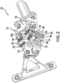
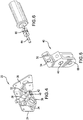
- the WOW sensing system 20 includes a mounting bracket 22 positionable in contact with the airframe 14.
- the WOW sensing system 20 is adapted for placement at the same location as conventional WOW systems, such as within the stub wings of the aircraft 10 for example.
- a first surface 24 of the bracket 22 is arranged in direct contact with a corresponding surface 26 of the airframe 14.
- first surface 24 of the bracket 22 and the surface 26 of the airframe 14 have generally complementary contours.
- the surfaces 24, 26 of the bracket 22 and airframe 14 are generally planar.
- other contours are also contemplated herein.
- an opening 30 formed in the bracket 22 is substantially aligned with an opening 32 (see FIGS. 8 and 9 ) formed in the airframe 14.
- a support 36 Protruding from a second surface 34 of the bracket 22, opposite the first surface 24 of the bracket 22, is a support 36.
- the support 36 is vertically aligned with the opening 30.
- the support 36 may be connected to the second surface 34 of the bracket 22, or may be integrally formed therewith.
- the support 36 is generally triangular in shape; however, a support 36 having any shape is within the scope of the disclosure.
- the support 36 may be solid, or alternatively, may have a generally hollow interior to reduce the overall weight of the bracket 22.
- the bracket 22 has a generally angled configuration.
- the support 36 may be connected to both the second surface 34 and an adjacent surface 38 defined by the angle to increase the structural rigidity thereof.
- the bracket 22 is illustrated as having a right angle, other suitable angles are also within the scope.
- a lever or indicator 40 is pivotally coupled to the support extending from the bracket 22.
- the support 36 defines a hollow cavity 42 within which the lever 40 is received.
- the lever 40 may be positioned adjacent either side of the support 36.
- a first shaft 44 extends through a centrally located through hole 46 formed in the lever 40 and an adjacent opening 48 formed in the support 36 to couple the lever 40 to the support 36 to define an axis of rotation R of the lever 40.
- a first end 50 of the lever 40 extends generally beyond an upper surface 52 of the support 36.
- the first end 50 of the lever 40 additionally includes a through hole 54 for receiving a second shaft 56 therein.
- a horizontally oriented pin 58 is arranged at an upper surface 60 of the bracket 22, generally adjacent the second surface 34.
- the second shaft 56 may be coupled to the pin 58 via at least one biasing mechanism 62.
- the second shaft 56 may be coupled to the airframe 14 via at least one biasing mechanism 62.
- a first biasing mechanism 62a is coupled to a first portion of the pin 58 and a portion of the second shaft 56 adjacent a first side 64 of the lever 40 and a second biasing mechanism 62b is coupled to a second portion of the pin 58 and a portion of the second shaft 56 adjacent a second, opposite side 66 of the lever 40.
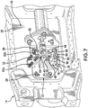
- the biasing force of the at least one biasing mechanism 62 is configured to bias the lever 40 about the rotational axis R defined by the first shaft in the direction indicated by arrow A (see FIG. 8 ).
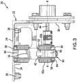
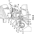
- a linkage assembly 70 (best shown in FIGS. 8 and 9 ) associated with the landing gear of the aircraft 10 is operably coupled to the lever 40.
- the linkage assembly 70 includes a drag beam lever arm 72 having a first end 74 configured to connect to the drag beam of the landing gear and a second end 76 coupled to a push rod 78.
- a first end 80 of the push rod 78 may be directly connected to the second end 76, or alternatively, an intermediate link 82 may couple the end 80 of the push rod 78 and the drag beam lever arm 72.
- the push rod 78 extends through the aligned openings 30, 32 formed in the airframe 14 and bracket 22, such that a second end 84 of the push rod 78 is located near the support 36 and lever 40.
- the second end 84 of the push rod 78 is connected to a second end 68 of the lever 40, either directly, or via one or more links.
- the second end 84 of the push rod is offset from the second end of the lever 40, such that a first connector 86 and a second connector 88 extend there between.
- the first connector 86 may include a through hole within which the second end 84 of the push rod 78 is received and a nut 90 may be used to restrict movement of the first connector 86 from the second end 84.
- the first connector 86 is oriented generally perpendicular to the axis defined by the push rod 78
- the second connector 88 is oriented generally parallel to the axis defined by the push rod 78.
- other configurations of a linkage assembly 70 are also contemplated herein.
- connection between the linkage assembly 70 and the second end of the lever 40 drives rotation of the lever 40 about the axis of rotation R, in response to a position of the landing gear.
- the drag beam moves causing the push rod 78 connected thereto to translate relative to the airframe 14 and bracket 22.
- This translation applies a force to the second end 68 of the lever 40, causing the lever 40 to rotate about the axis R. Accordingly, the position of the lever 40 relative to the axis indicates a current state of the landing gear.
- positioning sensing mechanism 90 such as a rotary variable differential transformer (VDT), position sensor, or potentiometer for example, is mounted to the first shaft 44 at a position between the lever 40 and the surface 38 of the bracket 22.
- VDT rotary variable differential transformer
- the system 20 described herein may be adapted for use with a linear positioning sensing mechanism 90.
- the first shaft 44 is operably coupled to the second surface 34 to support the VDT in an optimum position.
- the rotary VDT 90 is operable to sense rotation of the first shaft 44, and therefore the lever 40 about axis R, to determine a status of the landing gear.
- the rotary VDT 90 may communicate with a flight control system of the aircraft to communicate the status of a corresponding landing gear.
- the connection between the linkage assembly 70 and the second end 68 of the lever 40 opposes the biasing force of the biasing mechanism 62 acting on the first end 50 of the lever 40.
- the linkage assembly 70 such as a breakage thereof for example
- the push rod 78 will not apply a force to the lever 40.
- the biasing force of the biasing mechanism 62 causes the lever to rotate in the direction indicated by arrow A, to a position beyond a normal operating range associated with movement of the drag beam.
- the lever 40 will rotate as far about the axis R in the direction of arrow A as possible.
- an alternative WOW sensing system 120 includes a linkage assembly 122 similar to the linkage assembly 70 of the previous embodiments.
- the linkage assembly 122 may include a drag beam lever arm (not shown) having a first end connected to the drag beam of the landing gear and a second end coupled to a push rod 124.
- One or more biasing mechanisms 126 extend from a surface of the airframe 14, or alternatively, from a mounting bracket such as bracket 22 for example, and connect to a free end 128 of the push rod 124.
- the free end 128 of the push rod 124 may include a flange or have a diameter greater than the remainder of the push rod 124 to provide an area for attaching the at least one biasing mechanism 126.
- a position sensing mechanism 130 such as a linear VDT for example, is mounted to the airframe 14 and/or mounting bracket at a position offset from the pushrod 128.
- the VDT is operable to sense translation of the pushrod 124 along an axis to determine a status of the landing gear and may communicate the status of a corresponding landing gear to a flight control system of the aircraft.
- the force applied to the linkage assembly 122 in response to the landing gear opposes the biasing force of the at least one biasing mechanism 126 acting on the free end 128 of the push rod 124.
- the biasing force of the biasing mechanism 126 will cause the push rod 128 to translate about an axis to a position beyond a normal operating range associated with movement of the drag beam.
- the VDT 90, 130 is monitoring the position of a corresponding component, i.e. the first shaft 44 and lever 40 or the push rod 124, the VDT will detect movement of the component to a position indicative of a failure.
- the flight control system will process that the component is in the "failure position" and will determine that the WOW sensing system 20, 120 is not functioning properly and ignore any further output from the sensor system 20, 120.
Landscapes
- Engineering & Computer Science (AREA)
- Aviation & Aerospace Engineering (AREA)
- Physics & Mathematics (AREA)
- General Physics & Mathematics (AREA)
- Mechanical Engineering (AREA)
- Retarders (AREA)
- Tires In General (AREA)
Claims (11)
- Système de détection de poids sur roue (20 ; 120) à utiliser avec un train d'atterrissage d'un aéronef (10), le système (20 ; 120) comprenant :une timonerie (70 ; 122) conçue pour être reliée au train d'atterrissage ;un indicateur (40 ; 128) associé à la timonerie (70 ; 122) et pouvant ainsi se déplacer en réponse à une position du train d'atterrissage ;au moins un mécanisme de sollicitation (62 ; 126) couplé de manière opérationnelle à l'indicateur (40 ; 128) de sorte qu'une force de sollicitation du mécanisme de sollicitation (62 ; 126) est appliquée à l'indicateur (40 ; 128) ; etun mécanisme de détection de position (90 ; 130) couplé à l'indicateur (40 ; 128) pour déterminer une position de l'indicateur (40 ; 128) et pouvant être couplé de manière opérationnelle à un système de commande de vol pour communiquer une position de l'indicateur (40 ; 128) au système de commande de vol afin de déterminer un état opérationnel du système de détection de poids sur roue (20 ; 120) en réponse à la position de l'indicateur (40 ; 128).
- Système de détection de poids sur roue (20 ; 120) selon la revendication 1, dans lequel, en fonctionnement normal, le mouvement de la timonerie (70 ; 122) amène l'indicateur (40 ; 128) à se déplacer autour d'un axe (R) dans une amplitude de mouvement normale.
- Système de détection de poids sur roue (20 ; 120) selon la revendication 1 ou 2, dans lequel, en fonctionnement normal, la timonerie (70 ; 122) surmonte la force de sollicitation de l'au moins un mécanisme de sollicitation.
- Système de détection de poids sur roue (20 ; 120) selon l'une des revendications 1 à 3, dans lequel, pendant une défaillance du système de détection de poids sur roue (20 ; 120), la force de sollicitation de l'au moins un mécanisme de sollicitation (62 ; 126) amène l'indicateur (40 ; 128) à passer à une position de défaillance indiquant une défaillance du système de détection de poids sur roue (20, 120).
- Système de détection de poids sur roue (20 ; 120) selon l'une des revendications 1 à 4, dans lequel la timonerie (70 ; 122) comporte une bielle de poussée (78 ; 124), en particulier dans lequel l'indicateur (40 ; 128) est une extrémité libre de la bielle de poussée (78 ; 124) et le mécanisme de détection de position (90 ; 130) est un d'un transformateur différentiel variable linéaire, d'un potentiomètre et d'un capteur de position, couplé à l'extrémité libre de la bielle de poussée (78 ; 124).
- Système de détection de poids sur roue (20 ; 120) selon l'une des revendications 1 à 5, comprenant en outre :un support (22) ;dans lequel l'indicateur (40 ; 128) comporte un levier (40) monté sur le support (22) via un arbre (44), le levier (40) pouvant tourner autour d'un axe de rotation (R), en particulier dans lequel l'au moins un mécanisme de sollicitation (62 ; 126) est relié à une première extrémité (50) du levier (40), éventuellement dans lequel la timonerie (70 ; 122) est reliée à une seconde extrémité (68) du levier (40), dans lequel la timonerie (70 ; 122) est conçue pour se déplacer le long d'un axe.
- Agencement comprenant un train d'atterrissage d'un aéronef (10) et le système de détection de poids sur roue (20 ; 120) selon l'une des revendications 1 à 6, dans lequel la tringlerie (70, 122) est reliée au train d'atterrissage de l'aéronef (10).
- Aéronef (10) comprenant :une cellule (14) ;un train d'atterrissage couplé de manière opérationnelle à la cellule (14) ;le système de détection de poids sur roue (20 ; 122) selon l'une des revendications 1 à 6 associé au train d'atterrissage, dans lequel en cas de défaillance du système de détection de poids sur roue (20 ; 120), l'indicateur (40 ; 128) est automatiquement sollicité vers une position de défaillance indiquant la défaillance du système de détection de poids sur roue (20, 120).
- Aéronef (10) selon la revendication 8, comprenant en outre le système de commande de vol, le mécanisme de détection de position (90 ; 130) étant agencé en communication avec le système de commande de vol pour communiquer une position de l'indicateur (40 ; 128) et du train d'atterrissage.
- Aéronef (10) selon l'une des revendications 8 à 9, dans lequel le système de détection de poids sur roue (20 ; 120) est monté sur au moins un parmi la cellule (14) et le train d'atterrissage.
- Aéronef (10) selon l'une des revendications 8 à 10, dans lequel le système de détection de poids sur roues (20 ; 120) est monté à l'intérieur d'un moignon d'aile de l'aéronef (10) .
Applications Claiming Priority (1)
| Application Number | Priority Date | Filing Date | Title |
|---|---|---|---|
| US15/648,078 US10466093B2 (en) | 2017-07-12 | 2017-07-12 | Failsafe electromechanical weight on wheels detection |
Publications (2)
| Publication Number | Publication Date |
|---|---|
| EP3428071A1 EP3428071A1 (fr) | 2019-01-16 |
| EP3428071B1 true EP3428071B1 (fr) | 2021-03-31 |
Family
ID=62909458
Family Applications (1)
| Application Number | Title | Priority Date | Filing Date |
|---|---|---|---|
| EP18182715.5A Active EP3428071B1 (fr) | 2017-07-12 | 2018-07-10 | Détection de poids sur roues électromécanique à sécurité intégrée |
Country Status (2)
| Country | Link |
|---|---|
| US (1) | US10466093B2 (fr) |
| EP (1) | EP3428071B1 (fr) |
Family Cites Families (17)
| Publication number | Priority date | Publication date | Assignee | Title |
|---|---|---|---|---|
| US2587628A (en) * | 1949-01-24 | 1952-03-04 | Harold B King | Load stroke indicator |
| US3109505A (en) * | 1960-09-09 | 1963-11-05 | D & W Truck Load Indicator Ltd | Load measuring apparatus for vehicles |
| US3167142A (en) * | 1963-08-23 | 1965-01-26 | Pacific Coast Res & Dev Ltd | Self-compensating load indicator apparatus |
| US3488997A (en) * | 1966-08-22 | 1970-01-13 | Pneumo Dynamics Corp | Weight and center of gravity indication system |
| US3480095A (en) * | 1967-11-29 | 1969-11-25 | Railway Express Agency Inc | Axle loading indicator |
| US3499500A (en) * | 1968-02-29 | 1970-03-10 | Boeing Co | Strain-gauge weighing apparatus for vehicle support structure |
| US3517550A (en) * | 1968-05-08 | 1970-06-30 | Us Navy | Load and rate of change of load detection system |
| US3581836A (en) * | 1969-12-02 | 1971-06-01 | Fairchild Camera Instr Co | Method for reducing frictional errors in determining the weight of an object supported by a pneumatic or hydraulic device |
| US3955636A (en) * | 1973-06-01 | 1976-05-11 | Malcolm Anthony Askew | Weighing apparatus for truck and vehicle loads |
| US4312042A (en) * | 1979-12-12 | 1982-01-19 | Sundstrand Data Control, Inc. | Weight, balance, and tire pressure detection systems |
| US4756374A (en) * | 1987-03-31 | 1988-07-12 | Bailey John D | Vehicle load sensing device |
| US6575405B2 (en) | 1999-03-30 | 2003-06-10 | The Boeing Company | Control system and method for a semi-levered landing gear for an aircraft |
| US7609056B2 (en) | 2006-09-11 | 2009-10-27 | Fisher Controls International Llc | Apparatus to determine the position of an actuator |
| US20080099602A1 (en) | 2006-09-29 | 2008-05-01 | Zyss Michael J | System and method for detecting ground contact status of an air vehicle |
| EP3100950B1 (fr) | 2015-06-02 | 2018-10-10 | Safran Landing Systems UK Limited | Ensemble de train d'atterrissage d'avion |
| US10732023B2 (en) * | 2016-03-24 | 2020-08-04 | Sikorsky Aircraft Corporation | Measurement system for aircraft, aircraft having the same, and method of measuring weight for aircraft |
| FR3068004B1 (fr) * | 2017-06-26 | 2019-07-19 | Airbus Helicopters | Train d'atterrissage muni d'un dispositif embarque de mesure de charge pour un aeronef et aeronef |
-
2017
- 2017-07-12 US US15/648,078 patent/US10466093B2/en active Active
-
2018
- 2018-07-10 EP EP18182715.5A patent/EP3428071B1/fr active Active
Also Published As
| Publication number | Publication date |
|---|---|
| US10466093B2 (en) | 2019-11-05 |
| US20190017862A1 (en) | 2019-01-17 |
| EP3428071A1 (fr) | 2019-01-16 |
Similar Documents
| Publication | Publication Date | Title |
|---|---|---|
| EP1873057B1 (fr) | Mécanisme de palonnier actif avec tolérance de gâche d'objet étranger et frein articulé | |
| US8033500B1 (en) | Actuator load path monitoring system | |
| EP1878658A2 (fr) | Actionneur pour l'empennage d'un aéronef | |
| US9169735B2 (en) | Blade-pitch control system with feedback swashplate | |
| US10940957B2 (en) | Haptic alert mechanism for alerting an aircraft pilot, and an aircraft | |
| CN113365913B (zh) | 用于飞行器的控制棒的力施加设备 | |
| CN109850126B (zh) | 一种飞机操纵模块化综合控制装置 | |
| EP2778060B1 (fr) | Commande de pas de pale actif sans plateau cyclique avec contrainte mécanique delta-3 dotée d'une réponse de couplage pas-volet de lame instantanée | |
| EP3699082B1 (fr) | Commande de vol cyclique montée de façon compacte pour giravion | |
| EP3406518B1 (fr) | Module de sensation de capteur linéaire pour des commandes d'avion | |
| WO2011096913A1 (fr) | Actionneurs structurellement redondants | |
| EP3196119B1 (fr) | Giravion et système et procédé associés de surveillance de position de pale de rotor | |
| US11952111B2 (en) | Electronic control of blade pitch on a tiltrotor | |
| EP3133469B1 (fr) | Système et procédé de numérisation de composants de véhicule | |
| CN102712358B (zh) | 飞机机翼 | |
| EP3428071B1 (fr) | Détection de poids sur roues électromécanique à sécurité intégrée | |
| EP1966043B1 (fr) | Profil d'aile pour aeronef et aeronef | |
| CN116324219A (zh) | 具有故障检测的多载荷路径致动器 | |
| US11015652B2 (en) | Hybrid elastomeric self-lubricated bearing | |
| EP4049931B1 (fr) | Système de détection de charge de butée basse | |
| US20240400189A1 (en) | A fixed-wing control mechanism | |
| WO2016053410A9 (fr) | Système pour calage d'angle de pliage d'aube autour d'un axe de rotation | |
| US20250229894A1 (en) | Variable-length landing gear and aircraft equipped with such a landing gear | |
| US11104429B2 (en) | Blade moment adjustment system | |
| US5388961A (en) | Mechanical assembly for detecting the passing of a force threshold in translation |
Legal Events
| Date | Code | Title | Description |
|---|---|---|---|
| PUAI | Public reference made under article 153(3) epc to a published international application that has entered the european phase |
Free format text: ORIGINAL CODE: 0009012 |
|
| STAA | Information on the status of an ep patent application or granted ep patent |
Free format text: STATUS: THE APPLICATION HAS BEEN PUBLISHED |
|
| AK | Designated contracting states |
Kind code of ref document: A1 Designated state(s): AL AT BE BG CH CY CZ DE DK EE ES FI FR GB GR HR HU IE IS IT LI LT LU LV MC MK MT NL NO PL PT RO RS SE SI SK SM TR |
|
| AX | Request for extension of the european patent |
Extension state: BA ME |
|
| STAA | Information on the status of an ep patent application or granted ep patent |
Free format text: STATUS: REQUEST FOR EXAMINATION WAS MADE |
|
| 17P | Request for examination filed |
Effective date: 20190716 |
|
| RBV | Designated contracting states (corrected) |
Designated state(s): AL AT BE BG CH CY CZ DE DK EE ES FI FR GB GR HR HU IE IS IT LI LT LU LV MC MK MT NL NO PL PT RO RS SE SI SK SM TR |
|
| GRAP | Despatch of communication of intention to grant a patent |
Free format text: ORIGINAL CODE: EPIDOSNIGR1 |
|
| STAA | Information on the status of an ep patent application or granted ep patent |
Free format text: STATUS: GRANT OF PATENT IS INTENDED |
|
| RIC1 | Information provided on ipc code assigned before grant |
Ipc: G01G 19/07 20060101ALI20201207BHEP Ipc: G01B 7/30 20060101ALI20201207BHEP Ipc: B64D 45/00 20060101AFI20201207BHEP |
|
| INTG | Intention to grant announced |
Effective date: 20201222 |
|
| GRAS | Grant fee paid |
Free format text: ORIGINAL CODE: EPIDOSNIGR3 |
|
| GRAA | (expected) grant |
Free format text: ORIGINAL CODE: 0009210 |
|
| STAA | Information on the status of an ep patent application or granted ep patent |
Free format text: STATUS: THE PATENT HAS BEEN GRANTED |
|
| AK | Designated contracting states |
Kind code of ref document: B1 Designated state(s): AL AT BE BG CH CY CZ DE DK EE ES FI FR GB GR HR HU IE IS IT LI LT LU LV MC MK MT NL NO PL PT RO RS SE SI SK SM TR |
|
| REG | Reference to a national code |
Ref country code: GB Ref legal event code: FG4D Ref country code: CH Ref legal event code: EP |
|
| REG | Reference to a national code |
Ref country code: AT Ref legal event code: REF Ref document number: 1376679 Country of ref document: AT Kind code of ref document: T Effective date: 20210415 |
|
| REG | Reference to a national code |
Ref country code: DE Ref legal event code: R096 Ref document number: 602018014616 Country of ref document: DE |
|
| REG | Reference to a national code |
Ref country code: IE Ref legal event code: FG4D |
|
| REG | Reference to a national code |
Ref country code: LT Ref legal event code: MG9D |
|
| PG25 | Lapsed in a contracting state [announced via postgrant information from national office to epo] |
Ref country code: NO Free format text: LAPSE BECAUSE OF FAILURE TO SUBMIT A TRANSLATION OF THE DESCRIPTION OR TO PAY THE FEE WITHIN THE PRESCRIBED TIME-LIMIT Effective date: 20210630 Ref country code: BG Free format text: LAPSE BECAUSE OF FAILURE TO SUBMIT A TRANSLATION OF THE DESCRIPTION OR TO PAY THE FEE WITHIN THE PRESCRIBED TIME-LIMIT Effective date: 20210630 Ref country code: FI Free format text: LAPSE BECAUSE OF FAILURE TO SUBMIT A TRANSLATION OF THE DESCRIPTION OR TO PAY THE FEE WITHIN THE PRESCRIBED TIME-LIMIT Effective date: 20210331 Ref country code: HR Free format text: LAPSE BECAUSE OF FAILURE TO SUBMIT A TRANSLATION OF THE DESCRIPTION OR TO PAY THE FEE WITHIN THE PRESCRIBED TIME-LIMIT Effective date: 20210331 |
|
| PG25 | Lapsed in a contracting state [announced via postgrant information from national office to epo] |
Ref country code: SE Free format text: LAPSE BECAUSE OF FAILURE TO SUBMIT A TRANSLATION OF THE DESCRIPTION OR TO PAY THE FEE WITHIN THE PRESCRIBED TIME-LIMIT Effective date: 20210331 Ref country code: LV Free format text: LAPSE BECAUSE OF FAILURE TO SUBMIT A TRANSLATION OF THE DESCRIPTION OR TO PAY THE FEE WITHIN THE PRESCRIBED TIME-LIMIT Effective date: 20210331 Ref country code: RS Free format text: LAPSE BECAUSE OF FAILURE TO SUBMIT A TRANSLATION OF THE DESCRIPTION OR TO PAY THE FEE WITHIN THE PRESCRIBED TIME-LIMIT Effective date: 20210331 |
|
| REG | Reference to a national code |
Ref country code: NL Ref legal event code: MP Effective date: 20210331 |
|
| REG | Reference to a national code |
Ref country code: AT Ref legal event code: MK05 Ref document number: 1376679 Country of ref document: AT Kind code of ref document: T Effective date: 20210331 |
|
| PG25 | Lapsed in a contracting state [announced via postgrant information from national office to epo] |
Ref country code: AT Free format text: LAPSE BECAUSE OF FAILURE TO SUBMIT A TRANSLATION OF THE DESCRIPTION OR TO PAY THE FEE WITHIN THE PRESCRIBED TIME-LIMIT Effective date: 20210331 Ref country code: NL Free format text: LAPSE BECAUSE OF FAILURE TO SUBMIT A TRANSLATION OF THE DESCRIPTION OR TO PAY THE FEE WITHIN THE PRESCRIBED TIME-LIMIT Effective date: 20210331 Ref country code: SM Free format text: LAPSE BECAUSE OF FAILURE TO SUBMIT A TRANSLATION OF THE DESCRIPTION OR TO PAY THE FEE WITHIN THE PRESCRIBED TIME-LIMIT Effective date: 20210331 Ref country code: CZ Free format text: LAPSE BECAUSE OF FAILURE TO SUBMIT A TRANSLATION OF THE DESCRIPTION OR TO PAY THE FEE WITHIN THE PRESCRIBED TIME-LIMIT Effective date: 20210331 Ref country code: EE Free format text: LAPSE BECAUSE OF FAILURE TO SUBMIT A TRANSLATION OF THE DESCRIPTION OR TO PAY THE FEE WITHIN THE PRESCRIBED TIME-LIMIT Effective date: 20210331 Ref country code: LT Free format text: LAPSE BECAUSE OF FAILURE TO SUBMIT A TRANSLATION OF THE DESCRIPTION OR TO PAY THE FEE WITHIN THE PRESCRIBED TIME-LIMIT Effective date: 20210331 |
|
| PG25 | Lapsed in a contracting state [announced via postgrant information from national office to epo] |
Ref country code: IS Free format text: LAPSE BECAUSE OF FAILURE TO SUBMIT A TRANSLATION OF THE DESCRIPTION OR TO PAY THE FEE WITHIN THE PRESCRIBED TIME-LIMIT Effective date: 20210731 Ref country code: PL Free format text: LAPSE BECAUSE OF FAILURE TO SUBMIT A TRANSLATION OF THE DESCRIPTION OR TO PAY THE FEE WITHIN THE PRESCRIBED TIME-LIMIT Effective date: 20210331 Ref country code: PT Free format text: LAPSE BECAUSE OF FAILURE TO SUBMIT A TRANSLATION OF THE DESCRIPTION OR TO PAY THE FEE WITHIN THE PRESCRIBED TIME-LIMIT Effective date: 20210802 Ref country code: RO Free format text: LAPSE BECAUSE OF FAILURE TO SUBMIT A TRANSLATION OF THE DESCRIPTION OR TO PAY THE FEE WITHIN THE PRESCRIBED TIME-LIMIT Effective date: 20210331 Ref country code: SK Free format text: LAPSE BECAUSE OF FAILURE TO SUBMIT A TRANSLATION OF THE DESCRIPTION OR TO PAY THE FEE WITHIN THE PRESCRIBED TIME-LIMIT Effective date: 20210331 |
|
| REG | Reference to a national code |
Ref country code: DE Ref legal event code: R097 Ref document number: 602018014616 Country of ref document: DE |
|
| PG25 | Lapsed in a contracting state [announced via postgrant information from national office to epo] |
Ref country code: DK Free format text: LAPSE BECAUSE OF FAILURE TO SUBMIT A TRANSLATION OF THE DESCRIPTION OR TO PAY THE FEE WITHIN THE PRESCRIBED TIME-LIMIT Effective date: 20210331 Ref country code: AL Free format text: LAPSE BECAUSE OF FAILURE TO SUBMIT A TRANSLATION OF THE DESCRIPTION OR TO PAY THE FEE WITHIN THE PRESCRIBED TIME-LIMIT Effective date: 20210331 Ref country code: ES Free format text: LAPSE BECAUSE OF FAILURE TO SUBMIT A TRANSLATION OF THE DESCRIPTION OR TO PAY THE FEE WITHIN THE PRESCRIBED TIME-LIMIT Effective date: 20210331 |
|
| PLBE | No opposition filed within time limit |
Free format text: ORIGINAL CODE: 0009261 |
|
| STAA | Information on the status of an ep patent application or granted ep patent |
Free format text: STATUS: NO OPPOSITION FILED WITHIN TIME LIMIT |
|
| REG | Reference to a national code |
Ref country code: CH Ref legal event code: PL |
|
| 26N | No opposition filed |
Effective date: 20220104 |
|
| PG25 | Lapsed in a contracting state [announced via postgrant information from national office to epo] |
Ref country code: MC Free format text: LAPSE BECAUSE OF FAILURE TO SUBMIT A TRANSLATION OF THE DESCRIPTION OR TO PAY THE FEE WITHIN THE PRESCRIBED TIME-LIMIT Effective date: 20210331 |
|
| REG | Reference to a national code |
Ref country code: BE Ref legal event code: MM Effective date: 20210731 |
|
| PG25 | Lapsed in a contracting state [announced via postgrant information from national office to epo] |
Ref country code: LI Free format text: LAPSE BECAUSE OF NON-PAYMENT OF DUE FEES Effective date: 20210731 Ref country code: CH Free format text: LAPSE BECAUSE OF NON-PAYMENT OF DUE FEES Effective date: 20210731 |
|
| PG25 | Lapsed in a contracting state [announced via postgrant information from national office to epo] |
Ref country code: IS Free format text: LAPSE BECAUSE OF FAILURE TO SUBMIT A TRANSLATION OF THE DESCRIPTION OR TO PAY THE FEE WITHIN THE PRESCRIBED TIME-LIMIT Effective date: 20210731 Ref country code: LU Free format text: LAPSE BECAUSE OF NON-PAYMENT OF DUE FEES Effective date: 20210710 |
|
| PG25 | Lapsed in a contracting state [announced via postgrant information from national office to epo] |
Ref country code: IE Free format text: LAPSE BECAUSE OF NON-PAYMENT OF DUE FEES Effective date: 20210710 Ref country code: BE Free format text: LAPSE BECAUSE OF NON-PAYMENT OF DUE FEES Effective date: 20210731 |
|
| P01 | Opt-out of the competence of the unified patent court (upc) registered |
Effective date: 20230518 |
|
| PG25 | Lapsed in a contracting state [announced via postgrant information from national office to epo] |
Ref country code: CY Free format text: LAPSE BECAUSE OF FAILURE TO SUBMIT A TRANSLATION OF THE DESCRIPTION OR TO PAY THE FEE WITHIN THE PRESCRIBED TIME-LIMIT Effective date: 20210331 |
|
| PG25 | Lapsed in a contracting state [announced via postgrant information from national office to epo] |
Ref country code: HU Free format text: LAPSE BECAUSE OF FAILURE TO SUBMIT A TRANSLATION OF THE DESCRIPTION OR TO PAY THE FEE WITHIN THE PRESCRIBED TIME-LIMIT; INVALID AB INITIO Effective date: 20180710 Ref country code: GR Free format text: LAPSE BECAUSE OF FAILURE TO SUBMIT A TRANSLATION OF THE DESCRIPTION OR TO PAY THE FEE WITHIN THE PRESCRIBED TIME-LIMIT Effective date: 20210331 |
|
| PG25 | Lapsed in a contracting state [announced via postgrant information from national office to epo] |
Ref country code: MK Free format text: LAPSE BECAUSE OF FAILURE TO SUBMIT A TRANSLATION OF THE DESCRIPTION OR TO PAY THE FEE WITHIN THE PRESCRIBED TIME-LIMIT Effective date: 20210331 |
|
| PG25 | Lapsed in a contracting state [announced via postgrant information from national office to epo] |
Ref country code: MT Free format text: LAPSE BECAUSE OF FAILURE TO SUBMIT A TRANSLATION OF THE DESCRIPTION OR TO PAY THE FEE WITHIN THE PRESCRIBED TIME-LIMIT Effective date: 20210331 |
|
| PGFP | Annual fee paid to national office [announced via postgrant information from national office to epo] |
Ref country code: DE Payment date: 20250729 Year of fee payment: 8 |
|
| PGFP | Annual fee paid to national office [announced via postgrant information from national office to epo] |
Ref country code: IT Payment date: 20250721 Year of fee payment: 8 |
|
| PGFP | Annual fee paid to national office [announced via postgrant information from national office to epo] |
Ref country code: GB Payment date: 20250728 Year of fee payment: 8 |
|
| PGFP | Annual fee paid to national office [announced via postgrant information from national office to epo] |
Ref country code: FR Payment date: 20250725 Year of fee payment: 8 |
|
| PG25 | Lapsed in a contracting state [announced via postgrant information from national office to epo] |
Ref country code: TR Free format text: LAPSE BECAUSE OF FAILURE TO SUBMIT A TRANSLATION OF THE DESCRIPTION OR TO PAY THE FEE WITHIN THE PRESCRIBED TIME-LIMIT Effective date: 20210331 |