EP3428086A1 - Aufbewahrungs- und/oder transportsystem für transportable zaunelemente - Google Patents
Aufbewahrungs- und/oder transportsystem für transportable zaunelemente Download PDFInfo
- Publication number
- EP3428086A1 EP3428086A1 EP17002015.0A EP17002015A EP3428086A1 EP 3428086 A1 EP3428086 A1 EP 3428086A1 EP 17002015 A EP17002015 A EP 17002015A EP 3428086 A1 EP3428086 A1 EP 3428086A1
- Authority
- EP
- European Patent Office
- Prior art keywords
- frame
- support
- profile
- foot
- fence elements
- Prior art date
- Legal status (The legal status is an assumption and is not a legal conclusion. Google has not performed a legal analysis and makes no representation as to the accuracy of the status listed.)
- Pending
Links
Images


Classifications
-
- B—PERFORMING OPERATIONS; TRANSPORTING
- B65—CONVEYING; PACKING; STORING; HANDLING THIN OR FILAMENTARY MATERIAL
- B65D—CONTAINERS FOR STORAGE OR TRANSPORT OF ARTICLES OR MATERIALS, e.g. BAGS, BARRELS, BOTTLES, BOXES, CANS, CARTONS, CRATES, DRUMS, JARS, TANKS, HOPPERS, FORWARDING CONTAINERS; ACCESSORIES, CLOSURES, OR FITTINGS THEREFOR; PACKAGING ELEMENTS; PACKAGES
- B65D61/00—External frames or supports adapted to be assembled around, or applied to, articles
-
- B—PERFORMING OPERATIONS; TRANSPORTING
- B65—CONVEYING; PACKING; STORING; HANDLING THIN OR FILAMENTARY MATERIAL
- B65D—CONTAINERS FOR STORAGE OR TRANSPORT OF ARTICLES OR MATERIALS, e.g. BAGS, BARRELS, BOTTLES, BOXES, CANS, CARTONS, CRATES, DRUMS, JARS, TANKS, HOPPERS, FORWARDING CONTAINERS; ACCESSORIES, CLOSURES, OR FITTINGS THEREFOR; PACKAGING ELEMENTS; PACKAGES
- B65D85/00—Containers, packaging elements or packages, specially adapted for particular articles or materials
- B65D85/64—Containers, packaging elements or packages, specially adapted for particular articles or materials for bulky articles
-
- E—FIXED CONSTRUCTIONS
- E01—CONSTRUCTION OF ROADS, RAILWAYS, OR BRIDGES
- E01F—ADDITIONAL WORK, SUCH AS EQUIPPING ROADS OR THE CONSTRUCTION OF PLATFORMS, HELICOPTER LANDING STAGES, SIGNS, SNOW FENCES, OR THE LIKE
- E01F7/00—Devices affording protection against snow, sand drifts, side-wind effects, snowslides, avalanches or falling rocks; Anti-dazzle arrangements ; Sight-screens for roads, e.g. to mask accident site
-
- E—FIXED CONSTRUCTIONS
- E04—BUILDING
- E04H—BUILDINGS OR LIKE STRUCTURES FOR PARTICULAR PURPOSES; SWIMMING OR SPLASH BATHS OR POOLS; MASTS; FENCING; TENTS OR CANOPIES, IN GENERAL
- E04H12/00—Towers; Masts or poles; Chimney stacks; Water-towers; Methods of erecting such structures
- E04H12/22—Sockets or holders for poles or posts
- E04H12/2238—Sockets or holders for poles or posts to be placed on the ground
-
- E—FIXED CONSTRUCTIONS
- E04—BUILDING
- E04H—BUILDINGS OR LIKE STRUCTURES FOR PARTICULAR PURPOSES; SWIMMING OR SPLASH BATHS OR POOLS; MASTS; FENCING; TENTS OR CANOPIES, IN GENERAL
- E04H12/00—Towers; Masts or poles; Chimney stacks; Water-towers; Methods of erecting such structures
- E04H12/22—Sockets or holders for poles or posts
- E04H12/2253—Mounting poles or posts to the holder
- E04H12/2269—Mounting poles or posts to the holder in a socket
-
- E—FIXED CONSTRUCTIONS
- E04—BUILDING
- E04H—BUILDINGS OR LIKE STRUCTURES FOR PARTICULAR PURPOSES; SWIMMING OR SPLASH BATHS OR POOLS; MASTS; FENCING; TENTS OR CANOPIES, IN GENERAL
- E04H17/00—Fencing, e.g. fences, enclosures, corrals
- E04H17/14—Fences constructed of rigid elements, e.g. with additional wire fillings or with posts
- E04H17/16—Fences constructed of rigid elements, e.g. with additional wire fillings or with posts using prefabricated panel-like elements, e.g. wired frames
- E04H17/165—Fences constructed of rigid elements, e.g. with additional wire fillings or with posts using prefabricated panel-like elements, e.g. wired frames using panels with rigid filling and frame
-
- E—FIXED CONSTRUCTIONS
- E04—BUILDING
- E04H—BUILDINGS OR LIKE STRUCTURES FOR PARTICULAR PURPOSES; SWIMMING OR SPLASH BATHS OR POOLS; MASTS; FENCING; TENTS OR CANOPIES, IN GENERAL
- E04H17/00—Fencing, e.g. fences, enclosures, corrals
- E04H17/14—Fences constructed of rigid elements, e.g. with additional wire fillings or with posts
- E04H17/16—Fences constructed of rigid elements, e.g. with additional wire fillings or with posts using prefabricated panel-like elements, e.g. wired frames
- E04H17/18—Corrals, i.e. easily transportable or demountable enclosures
-
- E—FIXED CONSTRUCTIONS
- E04—BUILDING
- E04G—SCAFFOLDING; FORMS; SHUTTERING; BUILDING IMPLEMENTS OR AIDS, OR THEIR USE; HANDLING BUILDING MATERIALS ON THE SITE; REPAIRING, BREAKING-UP OR OTHER WORK ON EXISTING BUILDINGS
- E04G21/00—Preparing, conveying, or working-up building materials or building elements in situ; Other devices or measures for constructional work
- E04G21/24—Safety or protective measures preventing damage to building parts or finishing work during construction
- E04G2021/248—Tarpaulins specially adapted therefor
-
- E—FIXED CONSTRUCTIONS
- E04—BUILDING
- E04G—SCAFFOLDING; FORMS; SHUTTERING; BUILDING IMPLEMENTS OR AIDS, OR THEIR USE; HANDLING BUILDING MATERIALS ON THE SITE; REPAIRING, BREAKING-UP OR OTHER WORK ON EXISTING BUILDINGS
- E04G21/00—Preparing, conveying, or working-up building materials or building elements in situ; Other devices or measures for constructional work
- E04G21/32—Safety or protective measures for persons during the construction of buildings
- E04G21/3204—Safety or protective measures for persons during the construction of buildings against falling down
- E04G21/3223—Means supported by building floors or flat roofs, e.g. safety railings
- E04G21/3233—Means supported by building floors or flat roofs, e.g. safety railings without permanent provision in the floor or roof
Definitions
- the invention is directed to a device for storing and / or transporting portable fence elements, comprising a frame, to which individual fence elements are attached in parallel.
- the DE 10 2011 108 797 A1 discloses a transport pallet for the transport of fence elements. This comprises a flat base and two of these in an upright position folding side elements between which the fence elements can be arranged. On the one hand, there is a lack of a possibility for locking the charged fence elements; On the other hand, a possibility for locking of the fence elements holding feet. However, such feet are essential if a fence is not to be anchored in the ground, but is temporarily placed, for example. For the closure of a construction site or as a screen on highways in the area of an accident site.
- the frame has a lower foot area for placement on the floor or on a loading area, an upper supporting area for attaching the individual fence elements, as well as an upwardly projecting tripod area for supporting the supporting area on the foot area.
- Such a construction divides the frame into three essential elements.
- the foot area is intended to serve for torsion-free or at least low-torsion support on a substrate, in particular on a loading area.
- the support area fulfills the actual purpose of the frame, namely to securely hold and carry the attached fence elements. It is the task of the stand area to connect the lower foot area and the upper support area to one another as rigidly as possible.
- foot profiles which run parallel to each other at a mutual distance.
- These two foot profiles can either be placed on a ground in a hall where the fence elements and feet are to be kept, or they can be placed on a cargo bed of a vehicle or trailer and preferably fixed, for example. By screws.
- the invention is characterized in that the two foot profiles by at least one also horizontally extending connection profile connected to each other.
- This connection profile is intended to permanently set the distance between the two foot profiles to a desired value, whereby the frame according to the invention maintains its dimensional stability.
- connection profile can best meet when it is perpendicular to the two foot profiles.
- connection profile connects the centers of the two foot profiles together. This results in a symmetrical arrangement that guarantees safe road holding during transport.
- the invention can be further developed such that the hold-down (s) for holding over reaching feet for the fence elements in the region of the connection profile is (-en).
- the local connection profile can be transferred a multiple function, namely on the one hand to ensure the dimensional stability of the frame according to the invention, on the other hand, the support of feet, especially in the lower part of the frame, so that the focus is as low as possible with plugged feet and when mounted on a vehicle or trailer gives a good roadholding.
- the insertion or insertion of feet is made possible by the fact that at least one parallel groove is provided in the region of the connection profile. In this can, in the longitudinal direction of the slot one behind the other a variety of feet are inserted.
- At least one such groove which is parallel to a connecting profile, can have a cross-section approximately rectangular in cross-section. It is a very simple construction. To go with it To save material, the upper edge of such a recess can be offset from the lower edge to the outside. The weight of the feet rests on a base, for example. On the back of a truck or trailer, which must therefore be designed to be stable.
- the arrangement can also be such that at least one angle profile parallel to a connection profile with a correspondingly fluted cross-section is provided.
- the invention further provides that at least one angle profile has a thinner cross-section than the connection profile.
- the angle profile does not have to fulfill a stabilizing function due to the adjacently extending connection profile for the frame itself: on the other hand, weight can be saved by this measure, which facilitates transport.
- connection profile and / or another angle profile preferably by webs, which have a mutual distance.
- Such webs relieve the relevant angle profile by being derived on those forces acting on just these webs on a short path to the Veitatisprofil or another (angle) profile.
- At least one angle profile is arranged at a level below the connection profile, at a vertical distance from the connection profile. Such an angle profile is able to overlap holding the underlying feet held.
- the last-described embodiment of the invention can be further developed such that the height of the vertical leg of an angle profile about the thickness of a plate-shaped part of the stand for the fence elements corresponds, in particular the entire thickness of an elongated plate of the base in the region of a narrow end face of the same.
- the slot is adapted in terms of its width to the réellestckenden feet, the feet find therein sufficient support, so that can be dispensed with a further support of the feet, whereby on the one hand the material and on the other hand, the weight of the support device is minimized.
- the entire thickness of an elongate plate of the base is formed in the region of a narrow end side of the same by the thickness of the plate itself and by the thickness of a possibly attached to the underside, the anti-slip coating.
- the insertion slot is formed in terms of its width just for this entire extension of a stand, the feet can be easily inserted and also solve again.
- At least one angle profile can be offset relative to the connection profile, preferably offset in a direction perpendicular to the longitudinal axis of the connection profile, in particular at least partially in the horizontal direction.
- special requirements can be taken into account, for example.
- a non-slip floor covering attached to the underside of a pedestal should contain natural and / or synthetic rubber.
- a rather soft material can better adapt to bumps and will therefore find support on a road surface rather than a harder material.
- the invention recommends that the natural and / or synthetic rubber of a friction-increasing coating on the underside of a base is mixed with sulfur and vulcanized. This will make the mechanical Stress resistance of the material further improved, which od even in a rather rough operation on a construction site. Like. Does not cause damage.
- carbon black and / or zinc oxide and / or silicon dioxide and / or chalk and / or kaolin and / or antioxidants may be added to the natural and / or synthetic rubber of a friction-increasing coating on the underside of a base, preferably in a total amount of up to to 20% by weight or above. These substances give the friction-increasing coating particularly preferred properties.
- the anti-slip rubber covering is made, especially hard rubber.
- hard rubber can carry a greater weight, without a significant deformation.
- the frame may have in its foot region profiles with a U-shaped, open-topped cross-section, wherein the lower ends of the fence elements can slide into it.
- Such an arrangement serves to further secure the location of the charged fence elements, because those can only slide back and forth on the frame until one of the downwardly projecting male ends of a fence element abuts or rests against a side leg of a cross-sectionally U-shaped profile.
- the frame can be mounted on the back of a motor vehicle or a trailer for a motor vehicle, in particular screwed. As a result, it can not move relative to the subset concerned.
- the frame may have anchoring elements in its foot region for anchoring to a loading surface, preferably holes in the horizontal base profiles, in particular vertical bores in the end regions of the horizontal foot profiles. If the frame is so immovably connected to a loading area in the area of four corners of its base, it can neither tilt during a transport nor move in any other way relative to the relevant subset.
- the invention recommends that the loading frame of a motor vehicle or a trailer for a motor vehicle carrying a frame according to the invention has laterally fold-up tail lifts.
- tailgates can embrace one hand on the frame attached fence elements in its lower part and therefore protect against accidental slipping down;
- plugged feet can be embraced at their free end edges and thus preserved from unwanted slipping out of their slots.
- Another preferred design rule states that on the inside of a laterally fold-up liftgate elastic elements or an elastic covering is provided to fix in the frame inserted feet in the insertion slots. These elastic elements should be mounted in particular at the height of the slots, so that they rest on the free end faces of approximately horizontally out of the slot protruding feet feet and are as possible to hold those firmly in their slots or even press into those slots.
- a plug-in slot of the frame is limited in its horizontally measured insertion depth, preferably through the bottom of a groove or by a protruding into the insertion slot tab of the connection profile.
- Such an embodiment has the advantage that an inserted base can only be advanced to such a limit, so not so far that no base could be inserted on the opposite longitudinal side of the frame.
- the tripod portion of the frame may have two vertical columns, and preferably one or more oblique stiffening profiles. While it is up to the columns to divert the weight of the hanging on the frame fence elements vertically down, the purpose of the inclined stiffening profiles serve to avoid deformations of the frame, in particular twisting thereof.
- the columns are in the vertical center plane of the frame, preferably above the centers of the two foot profiles of the frame, so that the weight forces are transferred from there in equal parts to the two arms of the respective foot profile.
- a sloping stiffening profile may extend to the top of the column in question.
- the upper-side, supported by the tripod area supporting portion of the frame should have at least one horizontally extending support spar, which preferably extends parallel to the connecting profile of the foot region, in particular vertically above it.
- this vertical longitudinal midplane should point in the direction of travel to minimize drag or drag.
- At least one support beam of the support portion connects the upper ends of the vertical columns of the tripod, results - together with the lower side connecting profile - a rectangular frame, which receives a high mechanical stability by welding at the corners.
- a rectangular frame formed by the two horizontal profiles, namely the lower connecting profile and the upper supporting beam, on the one hand, and by the two pillars, on the other hand, can be further stiffened by inner, obliquely extending struts.
- inner, obliquely extending struts Of course, it would be conceivable to connect each two diametrically opposite corners of this rectangle frame together, so that there is an X-shaped stiffener. A simpler and about as stiff arrangement is obtained, however, when two such stiffening struts do not cross over from the lower corners of the rectangular frame starting from each other, but together strive towards a central region of the upper side supporting beam.
- the support region of the frame should have at least one approximately horizontally extending, freely ending support arm, to which the fence elements are attachable.
- a support arm in the middle of one longitudinal side or per longitudinal side of the upper side support beam;
- two support arms per front side of the frame ie in each case in the region of a column, because in that case the weight forces of attached fence elements can be initiated by the upper spar directly into the columns.
- the invention is further characterized in that the support region of the frame has at least one pair of parallel and approximately horizontally extending, freely ending support arms, preferably two such pairs, which point in opposite directions, in particular approximately perpendicular to a plane spanned by the rectangular frame level , At each two such support arms, a fence element can be attached. As a result, an attached fence element can not get into vibration even during a restless ride.
- At least one support arm can be connected to at least one support spar of the support region and preferably cantilevered from that.
- a stable support of a support arm is guaranteed in / on the spar.
- two support arms are each formed by a respective rod-shaped profile, which passes through the support spar of the support area.
- a profile for such support arms is particularly suitable a hollow profile, which has a maximum load capacity.
- At least one support arm should have a hook-shaped upwardly projecting member at its free end so that an attached fence member is prevented from sliding down the support arm under the influence of its weight from the upwardly projecting member.
- a fence element can be attached to the support arms, it is recommended by the invention that a fence element is provided in the region of its upper side as a counterpart to each support arm with one or more hooks, eyelets or temples whose nose or opening on the free End of a support arm is pushed.
- These hooks, brackets or eyes can be made of a bent metal rod, which is preferably fixed to both ends of the relevant fence element, in particular welded.
- a fence element has a frame with a filling of intersecting rods or wires.
- Such a construction can be achieved with minimal weight. Because an outer frame is able to give the fence element in itself already the required stability, so that the filling of stabilizing tasks is exempt. The filling can therefore be realized with minimal effort, for example, with intersecting rods and wires.
- a fence element has a fabric, preferably made of an opaque, but permeable material.
- a fabric preferably made of an opaque, but permeable material.
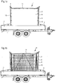
- the device 1 shown in the drawing for storage and / or transport of portable fence elements 2 and their feet 3 comprises a frame 4, what individual fence elements 2 are parallel to each other appended.
- a set of such fence elements 2 together with the respective frame 4 can be loaded on a trailer 5.
- This allows the relevant fence elements 2 to be transported quickly to their desired location.
- the fence elements 2 according to the invention together with specially designed feet 3 can be quickly set up and dismantled and are therefore particularly suitable for short-term use, for example as a privacy screen in car accidents or for one-off events, but also at construction sites , etc.
- the mobility of the system is very important.
- the frame 4 has a vertical rectangular frame 6, which is placed approximately centrally on the back of the trailer 5, such that its longitudinal extent in the direction of travel of the respective trailer 5 has.
- FIGS. 1 a and 1 b differ in that in Fig. 1 a fence elements 2 are charged with a fabric 8 made of an opaque material, while in accordance with Fig. 1b loaded fencing elements 2 such a fabric 8 is weggelasssen so that you can see the underlying construction of a fence element 2, consisting of a rectangular frame 9 with two columns 10 and two horizontal struts 11, said rectangular frame 9 with a filling in the form of a mat crossed, vertical and horizontal metal bars 12 is provided. This filling of intersecting metal rods 12 is used in the normal case de covering 8 as a guide.
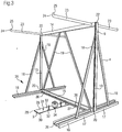
- FIG. 2 you can see how the arrangement looks like Fig. 1b appears when the frame 4 is removed from the trailer 5. It can be seen clearly the two columns 13 of the rectangular frame 6 and an upper, horizontal support beam 14 and a lower, also horizontal connection profile 15 thereof. This central rectangular frame 6 of the frame 4 is still better in Fig. 3 recognizable, where the fence elements 2 are removed from the frame 4.
- each foot section 16 extends perpendicular to the plane defined by the vertical rectangular frame 6 of the frame 4 level and is divided by that in each preferably two equal length arms 17.
- each column 13 of the rectangular frame 6 is supported by two obliquely extending stiffening struts 18.
- Each of these stiffening struts 18 extends from an arm 18 of a foot profile 16, preferably approximately from the center of the arm 17 concerned, to the relevant pillar 13, preferably up to the upper area or to the upper end of the pillar 13 concerned This results in an obliquely inclined course, which gives the frame 4 a high stability.
- a further stabilization undergoes the frame 4 by two further stiffening struts 19. These extend from a respective lower corner 20 of the vertical rectangular frame 6, or from the center of a candidatureprofils 16 or of an end portion of the lower side, the two foot sections 16 interconnecting Veitatisprofils 15th starting upwards, but not vertically, but inclined within the plane of the rectangular frame 6, in particular each striving towards a central region of the upper-side support beam 14, with which they are firmly connected, for example. Welded.
- each two stiffening struts 18 together with a foot profile 16 form a triangle which maintains the upper ends of the columns 13, while on the other hand two stiffening struts 19 together with the connection profile 16 form another triangle which serves to the rectangular frame 6 in Keep shape, such that the right angles are maintained at the corners even under stress.
- this may be vertical screw holes in the base profiles 16, which are arranged at the end, through which screws can be inserted, with which the frame 4 is screwed tightly onto the loading surface of the trailer 5.
- each two such support arms 23 are in a common flight and enforce the support beam 14.
- Such a pair of support arms 23 may consist of a single, continuous profile, preferably of a hollow profile, which has a maximum load capacity.
- Such a continuous profile is connected to the stabilizer by the support beam 14 by being pushed so far through an opening in the same until it protrudes approximately equally on both sides and thus forms two equal length support arms 23. Then, the profile can be welded on both sides with the support beam 14, so that two welds are formed at a distance from each other, which corresponds to the horizontal thickness of the support beam 14.
- the free end faces 24 of the support arms may be bent upward or be provided with upwardly projecting lugs 25, so that an attached fence element 2 can not accidentally slide from such a support arm 23.
- the frame 3 has below the hanging thereon fence elements 2 via hold-downs for retaining overlap of stored therebelow feet 3 for the fence elements. 2
- Such a base 3 is in Fig. 3 to be seen in the stored state. It comprises an elongated, preferably rectangular base plate 28 made of a heavy, stable material, for example iron or steel.
- This base plate 28 has, for example, a thickness of 4 mm or more, preferably 7 mm or more, more preferably 10 mm or more.
- a friction-increasing coating 30 may be provided, preferably made of a vulcanized natural or synthetic rubber, in particular of hard rubber.
- this covering 30 also has a thickness of 4 mm or more, for example.
- the total thickness of a stand 3 in the region of a shorter end face 29 thereof is usually 8 mm or more, eg. 14 mm or more, preferably 20 mm or more.
- the base plate 28 may be penetrated by two or more mounting holes 31 so that it can be dowelled or otherwise anchored to a substrate, for example. Od with a ground spike. The like.
- Upper side carrying handles 32 - for example in the form of U-shaped brackets - allow quick and convenient handling of the respective stand.
- a stand 3 has approximately in the center of its upper side 33 over several - in the case shown four - upstanding stand sleeves 34, in each of which a lower, foot-like extension 27 of a fence element 2 can be inserted.
- stand sleeves 34 in each of which a lower, foot-like extension 27 of a fence element 2 can be inserted.
- a continuous fence usually meet only two fence elements 2 in the area of a stand 3, so that usually only two sleeves 34 are needed.
- T-type branches or even X-shaped intersections of fence elements 2 may be required, for which then three or four sleeves 34 are required.
- one or two angle profiles 37 extend parallel to the connection profile 15, but at a distance from the connection profile 15.
- these angle profiles 37 can be connected to the connection profile 15, in particular via a plurality of short webs 38. This stabilization allows to carry out the angle sections 37 with a smaller cross-section than the connecting profile 15th
- the hold-down 36 results from the fact that between the underside of an upper-side, horizontal leg of an angle section 37 and a base, for example.
- the loading surface 50 of a trailer 5 or other (force) remains a gap, which is about or exactly the thickness of a stand in the region of its shorter end face 29 corresponds.
- an angle profile 37 may also be a horizontal offset between an angle profile 37 and the connection profile 15, in particular in such a way that the longitudinal edge of an angle profile 37 facing away from the plane of the vertical rectangular frame 6 has a greater distance from this plane of the rectangular frame 6 than the corresponding longitudinal edge of the frame Connection profile 15.
- an angle section 37 is displaced relative to the connection profile 15 to a free end of a foot profile 16 out.
- This construction makes it possible to push one or more feet 3 next to a respective shorter end face 29 into the gap 36 between an angle profile 37 and the base or loading area 50.
- a downwardly projecting web 39 of an angle section 37 form a stop against which the relevant stand 3 finally abuts, whereby a further or deeper insertion is prevented.
- a stand 3 is then overlapped and held down by the respective angle profile 37, wherein the shorter end face 29 of the base 3 cross web of the angle section 37 prevents the stand 3 under the influence of an uneven road surface to move away from its position can.
- the feet 3 holding down (-es) angle or angle profile 43 may be provided, the (the) when closing the tailgate 7 automatically the top 33 of the Base plates 28 of the feet 3 overlaps unintentional lifting a stand 3 safely excludes.
- the tail lift 7 is further on its inside 41 above the height of the groove 36 provided with an elastic coating 42. This is compressed when closing the tailgate 7 to a small extent and thereby presses an embraced fence element 2 elastically inward in the direction of the connection profile 15th
- FIG. 6a and 6b show Figures 6a and 6b how the fence elements 2 can be attached to the support arms 23.
- at least one bracket 44 is attached in the upper region of the rectangular frame 9 of a fence element 2.
- Such a bracket 44 is preferably located in the region of each upper corner 45 of the rectangular frame 9 of a fence element 2.
- This consists of a bent metal rod, which is bent, for example, by 90 ° or more, preferably by 120 ° or more, in particular by 150 ° or more in particular such that the ends 46, 47 of the bracket 44 point downwards.
- one end 46 of this bent bracket 44 is fastened to the upper horizontal strut 11 of the fence element 2, preferably welded, in particular in the region of the upper side of the relevant horizontal strut 11.
- the other end 48 of the bent bracket 44 may be inserted from above into the formed as a hollow tube, open-topped pillar 10 of the rectangular frame 9 of the respective fence element 2, as Fig. 6b shows.
- the bracket can be connected at two points with the column 10, for example. Welded, namely once in the region of the upper edge 48 of the column 10, and another time in the region of a specially introduced for this purpose in the shell of the tubular column 10 bore 49th
Landscapes
- Engineering & Computer Science (AREA)
- Architecture (AREA)
- Civil Engineering (AREA)
- Structural Engineering (AREA)
- Mechanical Engineering (AREA)
- Refuge Islands, Traffic Blockers, Or Guard Fence (AREA)
- Fencing (AREA)
- Road Signs Or Road Markings (AREA)
Applications Claiming Priority (5)
| Application Number | Priority Date | Filing Date | Title |
|---|---|---|---|
| DE202017003697 | 2017-07-14 | ||
| DE202017003695 | 2017-07-14 | ||
| DE202017003696.7U DE202017003696U1 (de) | 2017-07-14 | 2017-07-14 | Sichtblende zum Abschirmen von Unfällen |
| DE202017004180.4U DE202017004180U1 (de) | 2017-08-10 | 2017-08-10 | Aufbewahrungs- und/oder Transportsystem für transportable Zaunelemente |
| DE202017004181.2U DE202017004181U1 (de) | 2017-08-10 | 2017-08-10 | Sichtschutzelement |
Publications (1)
| Publication Number | Publication Date |
|---|---|
| EP3428086A1 true EP3428086A1 (de) | 2019-01-16 |
Family
ID=64604397
Family Applications (3)
| Application Number | Title | Priority Date | Filing Date |
|---|---|---|---|
| EP17002014.3A Active EP3428343B1 (de) | 2017-07-14 | 2017-12-12 | Sichtblende zum abschirmen von unfällen und standfuss dafür |
| EP17002015.0A Pending EP3428086A1 (de) | 2017-07-14 | 2017-12-12 | Aufbewahrungs- und/oder transportsystem für transportable zaunelemente |
| EP17002016.8A Active EP3428344B1 (de) | 2017-07-14 | 2017-12-12 | Sichtschutzelement |
Family Applications Before (1)
| Application Number | Title | Priority Date | Filing Date |
|---|---|---|---|
| EP17002014.3A Active EP3428343B1 (de) | 2017-07-14 | 2017-12-12 | Sichtblende zum abschirmen von unfällen und standfuss dafür |
Family Applications After (1)
| Application Number | Title | Priority Date | Filing Date |
|---|---|---|---|
| EP17002016.8A Active EP3428344B1 (de) | 2017-07-14 | 2017-12-12 | Sichtschutzelement |
Country Status (3)
| Country | Link |
|---|---|
| EP (3) | EP3428343B1 (da) |
| DK (1) | DK3428343T3 (da) |
| ES (1) | ES2828999T3 (da) |
Families Citing this family (4)
| Publication number | Priority date | Publication date | Assignee | Title |
|---|---|---|---|---|
| CN113796256A (zh) * | 2021-10-13 | 2021-12-17 | 云升 | 一种城市道路绿化带 |
| DE102022116470A1 (de) * | 2022-07-01 | 2024-01-04 | Peri Se | Gewichtssockel für eine mobile Anschlagvorrichtung, mobile Anschlagvorrichtung |
| WO2024163385A1 (en) * | 2023-01-30 | 2024-08-08 | Musco Corporation | Apparatus, method, and system for providing mobile or temporary fencing |
| AT528017B1 (de) | 2024-03-20 | 2025-09-15 | 3D Company Gmbh | mobiler Sichtschutz |
Citations (7)
| Publication number | Priority date | Publication date | Assignee | Title |
|---|---|---|---|---|
| DE9201229U1 (de) * | 1992-02-01 | 1992-06-17 | Sport-Thieme GmbH, 3332 Grasleben | Universalablagewagen für Rollbretter |
| FR2719296A1 (fr) * | 1994-04-27 | 1995-11-03 | Doussaint Louis | Dispositif de stockage et transport de barrières mobiles. |
| FR2790023A1 (fr) * | 1999-02-18 | 2000-08-25 | Soc Et & D Entreprises Electr | Ratelier mobile pour barrieres de chantier de voirie |
| FR2834960A3 (fr) * | 2002-01-21 | 2003-07-25 | Francis Mugnier | Remorque pour le transport et le stockage des barrieres mobiles |
| WO2010031122A1 (en) * | 2008-09-18 | 2010-03-25 | John Clement Preston | Fence panel support foot |
| DE102011108797A1 (de) | 2011-07-29 | 2013-01-31 | Aos Stahl Gmbh & Co. Kg | Transportpalette für den Transport von Zaunelementen |
| WO2017149043A1 (en) * | 2016-03-01 | 2017-09-08 | Mc Laughlin Patrick | An assembly for handling barriers |
Family Cites Families (7)
| Publication number | Priority date | Publication date | Assignee | Title |
|---|---|---|---|---|
| US4186912A (en) * | 1978-11-29 | 1980-02-05 | Byrd Clyde L Jr | Accident screen |
| US5553648A (en) * | 1995-08-14 | 1996-09-10 | Goharjou; Ardavan | Portable wall system |
| DE19638361A1 (de) | 1996-09-19 | 1998-04-02 | Markus Dr Hess | Sichtblende zum Abschirmen von Unfällen |
| ES1070756Y (es) * | 2009-07-30 | 2010-01-20 | Gil Miguel Rodriguez | Mampara asistencial |
| US20120067531A1 (en) * | 2010-09-16 | 2012-03-22 | Anna Ehrsam | Reconfigurable Shade |
| DE202014009447U1 (de) * | 2014-11-28 | 2015-02-10 | Wagner Werner Gmbh | Wind- und/oder Sichtschutzelement zur Applikation vor einem tragenden Element |
| WO2016139486A1 (en) * | 2015-03-04 | 2016-09-09 | Oxford Plastic Systems Limited | Base for a temporary barrier |
-
2017
- 2017-12-12 ES ES17002014T patent/ES2828999T3/es active Active
- 2017-12-12 EP EP17002014.3A patent/EP3428343B1/de active Active
- 2017-12-12 DK DK17002014.3T patent/DK3428343T3/da active
- 2017-12-12 EP EP17002015.0A patent/EP3428086A1/de active Pending
- 2017-12-12 EP EP17002016.8A patent/EP3428344B1/de active Active
Patent Citations (7)
| Publication number | Priority date | Publication date | Assignee | Title |
|---|---|---|---|---|
| DE9201229U1 (de) * | 1992-02-01 | 1992-06-17 | Sport-Thieme GmbH, 3332 Grasleben | Universalablagewagen für Rollbretter |
| FR2719296A1 (fr) * | 1994-04-27 | 1995-11-03 | Doussaint Louis | Dispositif de stockage et transport de barrières mobiles. |
| FR2790023A1 (fr) * | 1999-02-18 | 2000-08-25 | Soc Et & D Entreprises Electr | Ratelier mobile pour barrieres de chantier de voirie |
| FR2834960A3 (fr) * | 2002-01-21 | 2003-07-25 | Francis Mugnier | Remorque pour le transport et le stockage des barrieres mobiles |
| WO2010031122A1 (en) * | 2008-09-18 | 2010-03-25 | John Clement Preston | Fence panel support foot |
| DE102011108797A1 (de) | 2011-07-29 | 2013-01-31 | Aos Stahl Gmbh & Co. Kg | Transportpalette für den Transport von Zaunelementen |
| WO2017149043A1 (en) * | 2016-03-01 | 2017-09-08 | Mc Laughlin Patrick | An assembly for handling barriers |
Also Published As
| Publication number | Publication date |
|---|---|
| ES2828999T3 (es) | 2021-05-28 |
| EP3428344B1 (de) | 2020-07-01 |
| EP3428343B1 (de) | 2020-07-29 |
| EP3428344A1 (de) | 2019-01-16 |
| EP3428343A1 (de) | 2019-01-16 |
| DK3428343T3 (da) | 2020-11-02 |
Similar Documents
| Publication | Publication Date | Title |
|---|---|---|
| EP3428086A1 (de) | Aufbewahrungs- und/oder transportsystem für transportable zaunelemente | |
| DE3012010A1 (de) | Fahrzeugaufbau und dafuer bestimmte pfostenanordnung | |
| EP2832664B1 (de) | Lagervorrichtung für einen plattenförmigen Gegenstand | |
| DE102008061334A1 (de) | Vorrichtung zur Handhabung von schweren Gegenständen | |
| DE102015006053B4 (de) | Ladungssicherungsrungensystem für Nutzfahrzeuge | |
| DE29906239U1 (de) | Nutzfahrzeug für den Behältertransport | |
| DE4026157A1 (de) | Befestigungsvorrichtung | |
| DE19706493A1 (de) | LKW-Aufbau | |
| DE202017004180U1 (de) | Aufbewahrungs- und/oder Transportsystem für transportable Zaunelemente | |
| DE2943274A1 (de) | Vorrichtung zum verbinden von aufeinander gestapelten schaltafeln | |
| DE2922129A1 (de) | Mehrzweck- anlagen- gestaltungselement | |
| DE102016115786B4 (de) | Ladungssicherungseinrichtung für Nutzfahrzeuge | |
| DE2900055A1 (de) | Runge fuer ein lastfahrzeug | |
| DE2011593C3 (de) | Fahrgestell für Lastkraftwagenanhänger zum Transport auswechselbarer Ladeaufbauten | |
| DE1956809C3 (de) | Abnehmbare, vertikale Stütze für Fahrzeug-Ladeflächen mit einem Träger für eine Abdeckplane | |
| DE3016959A1 (de) | Fahrzeug mit wechselaufbau, insbesondere wohnmobil | |
| DE1285340B (de) | Sattelauflieger, insbesondere zum Transport vorgefertigter Bauteile fuer Haeuser | |
| DE9308619U1 (de) | Lastkraftwagen | |
| DE10303058B4 (de) | Runge mit integrierter Vorrichtung zur Ladungssicherung, insbesondere für Transportfahrzeuge mit Planenaufbauten | |
| DE19913616A1 (de) | Schiebeplanen-Aufbau | |
| DE202016102105U1 (de) | Scherengitterwagen | |
| DE102016108828A1 (de) | Nutzfahrzeugaufbau | |
| DE1193430B (de) | Aufsteckgestell fuer Paletten mit rechtwinkliger Ladeflaeche | |
| EP3275710B1 (de) | Gelenk mit schiebling | |
| DE1935265C3 (de) | Lastträgerteil für Lastkraftwagen |
Legal Events
| Date | Code | Title | Description |
|---|---|---|---|
| PUAI | Public reference made under article 153(3) epc to a published international application that has entered the european phase |
Free format text: ORIGINAL CODE: 0009012 |
|
| STAA | Information on the status of an ep patent application or granted ep patent |
Free format text: STATUS: THE APPLICATION HAS BEEN PUBLISHED |
|
| AK | Designated contracting states |
Kind code of ref document: A1 Designated state(s): AL AT BE BG CH CY CZ DE DK EE ES FI FR GB GR HR HU IE IS IT LI LT LU LV MC MK MT NL NO PL PT RO RS SE SI SK SM TR |
|
| AX | Request for extension of the european patent |
Extension state: BA ME |
|
| STAA | Information on the status of an ep patent application or granted ep patent |
Free format text: STATUS: REQUEST FOR EXAMINATION WAS MADE |
|
| 17P | Request for examination filed |
Effective date: 20190716 |
|
| RBV | Designated contracting states (corrected) |
Designated state(s): AL AT BE BG CH CY CZ DE DK EE ES FI FR GB GR HR HU IE IS IT LI LT LU LV MC MK MT NL NO PL PT RO RS SE SI SK SM TR |
|
| STAA | Information on the status of an ep patent application or granted ep patent |
Free format text: STATUS: EXAMINATION IS IN PROGRESS |
|
| 17Q | First examination report despatched |
Effective date: 20211124 |