EP3428087B1 - Kapsel - Google Patents
Kapsel Download PDFInfo
- Publication number
- EP3428087B1 EP3428087B1 EP18000561.3A EP18000561A EP3428087B1 EP 3428087 B1 EP3428087 B1 EP 3428087B1 EP 18000561 A EP18000561 A EP 18000561A EP 3428087 B1 EP3428087 B1 EP 3428087B1
- Authority
- EP
- European Patent Office
- Prior art keywords
- lid
- space
- central tube
- inflow space
- capsule
- Prior art date
- Legal status (The legal status is an assumption and is not a legal conclusion. Google has not performed a legal analysis and makes no representation as to the accuracy of the status listed.)
- Active
Links
Images

Classifications
-
- B—PERFORMING OPERATIONS; TRANSPORTING
- B65—CONVEYING; PACKING; STORING; HANDLING THIN OR FILAMENTARY MATERIAL
- B65D—CONTAINERS FOR STORAGE OR TRANSPORT OF ARTICLES OR MATERIALS, e.g. BAGS, BARRELS, BOTTLES, BOXES, CANS, CARTONS, CRATES, DRUMS, JARS, TANKS, HOPPERS, FORWARDING CONTAINERS; ACCESSORIES, CLOSURES, OR FITTINGS THEREFOR; PACKAGING ELEMENTS; PACKAGES
- B65D85/00—Containers, packaging elements or packages, specially adapted for particular articles or materials
- B65D85/70—Containers, packaging elements or packages, specially adapted for particular articles or materials for materials not otherwise provided for
- B65D85/804—Disposable containers or packages with contents which are mixed, infused or dissolved in situ, i.e. without having been previously removed from the package
- B65D85/8043—Packages adapted to allow liquid to pass through the contents
Definitions
- the invention relates to a generic capsule according to the preamble of the main claim, namely a capsule with an interior, with a bottom and with an oppositely arranged one, which is a beverage powder for the preparation of a portion of a hot brewed beverage such as coffee, tea or boullion when passing through Water-tight interior sealing lid.
- the capsule which is circular in cross section, can be provided with a conical wall between the base and the cover, the base which has just been formed merging into the conical wall via a truncated cone.
- Such a capsule is known and its use is generally very popular (such as in WO 2015/124534 A1 or EP 20 29 457 B1 ).
- the capsule is inserted into a brewing device, which perforates the lid and opens the bottom by means of steam lances, via which water vapor is pressed through the beverage powder to produce the hot brewing beverage, which flows out of the capsule and retains the beverage powder, holding it in a vessel, for example a cup, is directed.
- the water vapor is moved in one direction from the bottom to the lid by the beverage powder.
- a sufficiently high minimum pressure is required to obtain the hotest possible brewed beverage
- the flow rate of the water vapor is increased with increasing pressure, with the result that the beverage powder is only soaked, but not optimally soaked. This is where the invention comes in.
- the invention has for its object to design a generic capsule according to the preamble of the main claim so that the beverage powder is used optimally for the production of the brewed beverage.
- This object is achieved in a generic capsule according to the preamble of the main claim according to the invention by its characterizing features in that in the area of the floor there is an inflow space delimited by a partition wall (near the floor and away from the lid) from the interior that the interior is in relation to the floor
- the central tube has an upright shape, that a hollow cylindrical section is arranged around the central tube to form a radially inner and a radially outer annular space, that the inner annular space is closed on its side facing away from the inflow space and facing the cover (near the cover and away from the ground) and that both The central tube and the hollow cylinder section end at a distance from the cover.
- the invention is characterized in that the central tube is connected to the inflow space on its side near the bottom and is closed on the side near the cover and is provided with radial through openings there, and the hollow cylinder section is spaced from the partition wall both in its end near the bottom Leaving a connection of the inner to the outer annular space arranged as well as each annular space is separated from the inflow space.
- the water vapor first moves into the pipe section and from there via the inner and then the outer annular space to the perforated cover. Because of the deflections, the path of the water vapor is approximately twice as long as in the prior art of the generic type, with the result that better use is made of the powdered drink and also a more intense taste of the brewed beverage.
- the radially outer annular space can be formed by the wall.
- the capsule can expediently be inserted horizontally into the brewing device. With the same shape and dimension as in the genus, the capsule according to the invention can be used in the same brewing device used for the known capsules and can also be used if their steam lances open into the inflow space after the bottom has been opened.
- a capsule through which water vapor flows from the lid to the bottom is known in the opposite direction to that of the invention ( WO2017 / 068535A1 ), which has a central tube which is erected with respect to the floor, one open side of which is closed from the lid to the outside, but is open to the inside via radial openings and is closed by means of an inner closure in the direction of its other, opposite, side.
- the bottom of the capsule is closed at the other end of the central tube.
- the central tube is not completely flowed through by the water vapor.
- the lid is pierced with a steam lance and water vapor is applied to one open side of the central tube, which reaches the interior of the capsule via the nearby radial openings.
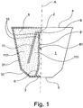
- the capsule 1 which is rotationally symmetrical with respect to the axis A and has a circular cross section in accordance with the first embodiment Figure 1 has an interior 2, which is arranged between a base 3 and with an oppositely arranged cover 4, which seals the interior 2 tightly and is known per se.
- a beverage powder 5 for the preparation of a portion of a hot brewed beverage such as coffee, tea or boullion when water vapor is passed through.
- the capsule 1 has a conical wall 31 between the Bottom 3 and the cover 4 provided, the floor 3 just formed merges into the conical wall 31 via a truncated cone 32.
- an inflow space 7 which can be of any shape and is delimited from the interior 2 by a partition wall 6 near the floor and away from the cover, is provided. Furthermore, the interior 2 has a central tube 8 which extends upright with respect to the base 3, into which the inflow space 7 opens and which is closed by means of a closure 9 at its end remote from the floor and close to the cover and away from the inflow space.
- the inflow space 7 can be designed as a conical section adjoining the central tube.
- the central tube 9 has radial through openings 10 in the region remote from the floor and near the cover and away from the inflow space 7.
- the central tube 8 can furthermore be provided in the region between its side near the floor, connected to the inflow space 7 and its closed 9 side close to the lid, with a plate 81 which can be penetrated by a steam lance of the brewing device as the central water vapor supply during operation.
- the base 3 can also be designed to be open in the area of the inflow space 7 or the central tube 9.
- a hollow cylindrical section 11 is arranged around the central tube 8, forming a radially inner 111 and a radially outer annular space 112.
- the inner annular space 111 is closed on its side facing away from the inflow space 7 and facing the cover 4, and is connected to the outer annular space 112 at its region near the floor at a distance from the partition wall 6, each annular space 111, 112 being separated from the inflow space 7 by the Partition 6 is separated.
- Both the central tube 8 and the hollow cylinder section 11 end at a distance from the cover 4.
- This capsule 1 is then inserted into a brewing device which is known per se and is not shown, the lid 4 being perforated to form the outlet for the brewed beverage and the base 3 being opened to the inflow space 7 by means of steam lances and water vapor in one direction from the base to the Presses the lid through the beverage powder 5 to produce the hot brewed beverage, which, for example, is retained by the perforation of the lid 4 while retaining the beverage powder 5 in a vessel a cup flows.
- the second embodiment of the capsule according to the invention Figure 2 differs from the first in that the dividing wall 6 is connected to the region of the transition of the wall 31 to the truncated cone 32 by increasing the volume of the inflow space 7, which can be advantageous when introducing the water vapor.
Landscapes
- Engineering & Computer Science (AREA)
- Mechanical Engineering (AREA)
- Apparatus For Making Beverages (AREA)
Description
- Die Erfindung betrifft eine gattungsgemässe Kapsel nach dem Oberbegriff des Hauptanspruchs, nämlich eine Kapsel mit einem Innenraum, mit einem Boden und mit einem dazu entgegengesetzt angeordneten, den ein Getränkepulver für die Zubereitung einer Portion eines heissen Brühgetränks wie Kaffee, Tee oder Boullion bei der Durchleitung von Wasserdampf aufweisenden Innenraum dicht verschliessenden Deckel. Dabei kann die im Querschnitt kreisförmige Kapsel mit einer konusförmigen Wandung zwischen dem Boden und dem Deckel versehen sein, wobei der eben ausgebildete Boden über einen Kegelstumpf in die konusförmige Wandung übergeht.
- Eine solche Kapsel ist bekannt und ihr Einsatz erfreut sich allgemein grosser Beliebtheit (wie zum Beispiel bei
WO 2015/124534 A1 oderEP 20 29 457 B1 ). Dabei wird die Kapsel in eine Brühvorrichtung eingesetzt, die dabei den Deckel perforiert und den Boden mittels Dampflanzen öffnet, über die Wasserdampf durch das Getränkepulver unter Erzeugung des heissen Brühgetränks gepresst wird, das durch den perforierten Deckel unter Zurückhaltung des Getränkepulvers aus der Kapsel herausfliesst und in ein Gefäss z.B. eine Tasse geleitet wird. - Dabei wird der Wasserdampf in einer Richtung von dem Boden zu dem Deckel durch das Getränkepulver bewegt. Dazu ist einerseits ein ausreichend hoher Minimaldruck erforderlich, um eine möglichst heisses Brühgetränk zu erhalten, andererseits wird bei zunehmendem Druck die Durchlaufgeschwindigkeit des Wasserdampfes mit der Folge vergrössert, dass das Getränkepulver nur an-, aber nicht optimal durchtränkt wird. Hier setzt die Erfindung an.
- Der Erfindung liegt die Aufgabe zugrunde, eine gattungsgemässe Kapsel nach dem Oberbegriff des Hauptanspruchs so auszubilden, dass das Getränkepulver optimal zur Herstellung des Brühgetränks genutzt wird.
- Diese Aufgabe wird bei einer gattungsgemässen Kapsel nach dem Oberbegriff des Hauptanspruchs erfindungsgemäss durch dessen kennzeichnenden Merkmale also dadurch gelöst, dass im Bereich des Bodens ein durch eine (bodennahe und deckelferne) Trennwandung von dem Innenraum begrenzter Einströmraum vorgesehen ist, dass der Innenraum ein bezüglich des Bodens aufgerichtet verlaufendes Zentralrohr aufweist, dass um das Zentralrohr herum ein Hohlzylinderabschnitt unter Bildung eines radial inneren sowie eines radial äusseren Ringraums angeordnet ist, dass der innere Ringraum auf seiner dem Einströmraum abgewandten und dem Deckel zugewandten (deckelnahen und bodenfernen) Seite verschlossen ist und dass sowohl das Zentralrohr als auch der Hohlzylinderabschnitt mit Abstand zu dem Deckel enden.
- Dabei zeichnet sich die Erfindung gemäss einer ersten Ausführungsform dadurch aus, dass das Zentralrohr an seiner bodennahen Seite mit dem Einströmraum verbunden und an der deckelnahen Seite verschlossen ausgebildet und dort mit radialen Durchtrittsöffnungen versehen und der Hohlzylinderabschnitt sowohl in seinem bodennahen Ende mit Abstand von der Trennwandung unter Belassen einer Verbindung des inneren mit dem äusseren Ringraums angeordnet als auch jeder Ringraum von dem Einströmraum abgetrennt ist.
- So bewegt sich bei dieser erfindungsgemässen Ausführungsform der Wasserdampf zunächst in den Rohrabschnitt und von dort über den inneren und danach den äusseren Ringraum zu dem perforierten Deckel. Wegen der Umlenkungen ist der Weg des Wasserdampfes etwa doppelt so lang wie beim gattungsgemässen Stand der Technik mit der Folge einer besseren Ausnutzung des Getränkepulvers und auch eines intensiveren Geschmacks des Brühgetränks. Dabei kann der radial äusseren Ringraum von der Wandung gebildet sein. Zweckmässigerweise kann die Kapsel liegend in die Brühvorrichtung eingesetzt werden. Bei gleicher Form und Dimension wie bei der Gattung kann die erfindungsgemässe Kapsel in denselben, für die bekannten Kapseln dienende Brühvorrichtung eingesetzt und dann auch genutzt werden, wenn deren Dampflanzen nach dem Öffnen des Bodens in den Einströmraum münden.
- Es ist zwar eine in umgekehrter Richtung wie bei der Erfindung nämlich vom Deckel zum Boden von Wasserdampf durchströmte Kapsel bekannt (
WO2017/068535A1 ), die ein bezüglich des Bodens aufgerichtet verlaufendes Zentralrohr aufweist, dessen eine offene Seite von dem Deckel nach aussen hin verschlossen, aber über radiale Öffnungen nach innen offen und mittels einen inneren Abschlusses in Richtung auf seine andere, entgegengesetzte hin Seite verschlossen ist. Mit dem anderen Ende des Zentralrohrs wird zugleich der Boden der Kapsel verschlossen. Allerdings wird das Zentralrohr nicht, wie bei der Erfindung, vollständig von dem Wasserdampf durchströmt. Mit einer Dampflanze wird der Deckel durchstossen und die eine offenen Seite des Zentralrohrs mit Wasserdampf beaufschlagt, der über die nahen radialen Öffnungen in das Innere der Kapsel gelangt. Zugleich geschieht zweierlei: zum einen wird dabei die faltbalgartige konusförmige Wandung unter Verringerung der Höhe der Kapsel zusammengeschoben; zum anderen wird das andere Ende des Zentralrohrs aus der Kapsel geschoben und diese dabei geöffnet, so dass das gebrühte Getränk herausfliessen kann. - Zweckmässige Ausgestaltungen und Weiterbildungen der Erfindung sind in den Unteransprüchen gekennzeichnet.
- Ein bevorzugtes Ausführungsbeispiel der Erfindung wird nachfolgend unter Bezugnahme auf die Zeichnung näher erläutert. In dieser zeigt:
- Figur 1
- eine erste Form einer erfindungsgemässe Kapsel, im schematischen Halbschnitt und
- Figur 2
- eine zweite Form einer erfindungsgemässe Kapsel, im schematischen Halbschnitt.
- Die bezüglich der Achse A rotationssymmetrische, im Querschnitt kreisförmige Kapsel 1 der ersten Ausführungsform gemäss
Figur 1 weist einen Innenraum 2 auf, der zwischen einem Boden 3 und mit einem dazu entgegengesetzt angeordneten, den Innenraum 2 dicht verschliessenden, an sich bekannten Deckel 4 angeordnet ist. In dem Innenraum 2 befindet sich ein Getränkepulver 5 für die Zubereitung einer Portion eines heissen Brühgetränks wie Kaffee, Tee oder Boullion bei der Durchleitung von Wasserdampf. Die Kapsel 1 ist mit einer konusförmigen Wandung 31 zwischen dem Boden 3 und dem Deckel 4 versehen, wobei der eben ausgebildete Boden 3 über einen Kegelstumpf 32 in die konusförmige Wandung 31 übergeht. - Im Bereich des Bodens ist ein durch eine bodennahe und deckelferne Trennwandung 6 von dem Innenraum 2 abgegrenzter Einströmraum 7 vorgesehen, der jegliche Form aufweisen kann. Ferner weist der Innenraum 2 ein bezüglich des Bodens 3 aufgerichtet verlaufendes Zentralrohr 8 auf, in das der Einströmraum 7 mündet und das an seinem bodenfernen und deckelnahen sowie dem Einströmraum abgewandten Ende mittels eines Abschlusses 9 geschlossen ist. In dem erstgenannten Fall kann der Einströmraum 7 als sich konusförmig an das Zentralrohr anschliessender Abschnitt ausgebildet sein. Im zweitgenannten Fall weist das Zentralrohr 9 in dem bodenfernen und deckelnahen sowie dem Einströmraum 7 abgewandten Bereich radiale Durchtrittsöffnungen 10 auf. Das Zentralrohr 8 kann weiterhin im Bereich zwischen seiner bodennahen, mit dem Einströmraum 7 verbundenene Seite und seiner deckelnahen verschlossenen 9 Seite mit einer -im Betrieb von einer Dampflanze der Brühvorrichtung als zentrale Wasserdampfzufuhr durchstossbaren- Platte 81 versehen sein. Bei dieser Ausgestaltung kann der Boden 3 im Bereich des Einströmraums 7 bzw. des Zentrahlrohrs 9 auch offen ausgebildet sein.
- An dem bodenfernen und deckelnahen sowie dem Einströmraum abgewandten Ende ist um das Zentralrohr 8 herum ein Hohlzylinderabschnitt 11 unter Bildung eines radial inneren 111 sowie eines radial äusseren Ringraums 112 angeordnet. Hierbei ist der innere Ringraum 111 auf seiner dem Einströmraum 7 abgewandten und dem Deckel 4 zugewandten Seite verschlossen und an seinem bodennahen Bereich mit Abstand von der Trennwandung 6 mit dem äusseren Ringraum 112 so verbunden, wobei jeder Ringraum 111, 112 von dem Einströmraum 7 durch die Trennwandung 6 abgetrennt ist. Sowohl das Zentralrohr 8 als auch der Hohlzylinderabschnitt 11 enden mit Abstand zu dem Deckel 4.
- Diese Kapsel 1 wird dann in eine an sich bekannte und nicht gezeigte Brühvorrichtung eingesetzt, wobei der Deckel 4 unter Bildung des Austritts für das Brühgetränk perforiert und der Boden 3 mittels Dampflanzen zu dem Einströmraum 7 geöffnet und darüber Wasserdampf in einer Richtung von dem Boden zu dem Deckel durch das Getränkepulver 5 unter Erzeugung des heissen Brühgetränks presst, das durch die Perforation des Deckels 4 unter Zurückhaltung des Getränkepulvers 5 in ein Gefäss z.B. eine Tasse fliesst.
- Die zweite Ausführungsform der erfindungsgemässen Kapsel nach
Figur 2 unterscheidet sich von der ersten dadurch, dass die Trennwandung 6 unter Vergrösserung des Volumens des Einströmraums 7 mit dem Bereich des Übergangs der Wandung 31 zu dem Kegelstumpf 32 verbunden ist, was beim Einleiten des Wasserdampfs von Vorteil sein kann.
Claims (10)
- Kapsel (1) mit einem Innenraum (2), mit einem Boden (3) und mit einem dazu entgegengesetzt angeordneten, den ein Getränkepulver (5) für die Zubereitung einer Portion eines heissen Brühgetränks wie Kaffee, Tee oder Boullion bei der Durchleitung von Wasserdampf aufweisenden Innenraum (2) dicht verschliessenden Deckel (4), dadurch gekennzeichnet, dass im Bereich des Bodens (3) ein durch eine bodennahe und deckelferne Trennwandung (6) von dem Innenraum (2) begrenzter Einströmraum (7) vorgesehen ist, dass der Innenraum (2) ein bezüglich des Bodens (3) aufgerichtet verlaufendes Zentralrohr (8) aufweist, dass um das Zentralrohr (8) herum ein Hohlzylinderabschnitt (11) unter Bildung eines radial inneren (111) sowie eines radial äusseren Ringraums (112) angeordnet ist, dass der innere Ringraum (111) auf seiner dem Einströmraum (7) abgewandten und dem Deckel (4) zugewandten deckelnahen und bodenfernen Seite verschlossen ist und dass sowohl das Zentralrohr (8) als auch der Hohlzylinderabschnitt (11) mit Abstand zu dem Deckel (4) enden, und dass das Zentralrohr (8) an seiner bodennahen Seite mit dem Einströmraum (7) verbunden und an der deckelnahen Seite verschlossen (9) ausgebildet und dort mit radialen Durchtrittsöffnungen (10) versehen und der Hohlzylinderabschnitt (11) sowohl in seinem bodennahen Ende mit Abstand von der Trennwandung (6) unter Belassen einer Verbindung des inneren mit dem äusseren Ringraums angeordnet als auch jeder Ringraum (111,112) von dem Einströmraum (7) abgetrennt ist.
- Kapsel nach Anspruch 1, dadurch gekennzeichnet, dass die Kapsel (1) bezüglich einer Achse (A) rotationssymmetrisch ausgebildet ist und dass der Einströmraum (7) von dieser Achse (A) durchquert ist.
- Kapsel nach Anspruch 1 oder 2, dadurch gekennzeichnet, dass das Zentralrohr (8), der Hohlzylinderabschnitt (11), die Trennwandung (6), die konusförmige Wandung (31), der Einströmraum (7) und/oder der Kegelstumpf (32) bezüglich der Achse (A) rotationssymmetrisch ausgebildet ist.
- Kapsel nach Anspruch 3, dadurch gekennzeichnet, dass der einerseits von der Trennwandung (6) begrenzte Einströmraum (7) von jenem Bereich des Bodens (3) begrenzt wird, der von dem Kegelstumpf (32) einen Abstand aufweist.
- Kapsel nach Anspruch 4, dadurch gekennzeichnet, dass der Einströmraum (7) an dem Boden (3) von einem kreisförmigen Bereich begrenzt wird, der über einen sich daran direkt anschliessenden Kreisring von dem Kegelstumpf (32) beabstandet ist.
- Kapsel nach Anspruch 1 oder 3, dadurch gekennzeichnet, dass das Zentralrohr (8) im Bereich zwischen seiner bodennahen, mit dem Einströmraum (7) verbundenene Seite und seiner deckelnahen verschlossenen Seite (9) mit einer durchstossbaren Platte (81) versehen ist.
- Kapsel nach Anspruch 6, dadurch gekennzeichnet, dass die durchstossbare Platte (81) näher an der deckelnahen verschlossenen Seite (9) als von dem Boden (3) angeordnet ist.
- Verwendung einer Kapsel nach einem der Ansprüche 1 bis 7 in einer Brühvorrichtung mit einer zentralen Wasserdampfzufuhr, vorzugsweise über eine Dampflanze.
- Verwendung nach Anspruch 8, dadurch gekennzeichnet, dass die Wasserdampfzufuhr mittig bezüglich der Achse (A) angeordnet ist.
- Verwendung nach Anspruch 8 oder 9, dadurch gekennzeichnet, dass nur eine einzige Wasserdampfzufuhr vorgesehen ist.
Applications Claiming Priority (2)
| Application Number | Priority Date | Filing Date | Title |
|---|---|---|---|
| DE202017003653.3U DE202017003653U1 (de) | 2017-07-12 | 2017-07-12 | Kapsel |
| PCT/IB2018/000004 WO2019012325A1 (de) | 2017-07-12 | 2018-01-04 | Kapsel |
Publications (2)
| Publication Number | Publication Date |
|---|---|
| EP3428087A1 EP3428087A1 (de) | 2019-01-16 |
| EP3428087B1 true EP3428087B1 (de) | 2020-05-27 |
Family
ID=62715797
Family Applications (1)
| Application Number | Title | Priority Date | Filing Date |
|---|---|---|---|
| EP18000561.3A Active EP3428087B1 (de) | 2017-07-12 | 2018-06-27 | Kapsel |
Country Status (1)
| Country | Link |
|---|---|
| EP (1) | EP3428087B1 (de) |
Family Cites Families (4)
| Publication number | Priority date | Publication date | Assignee | Title |
|---|---|---|---|---|
| CH708663A1 (de) * | 2013-10-04 | 2015-04-15 | Delica Ag | Kapsel und System zur Zubereitung eines flüssigen Lebensmittels, sowie Kapselkörper. |
| CH709295A1 (de) * | 2014-02-21 | 2015-08-28 | Delica Ag | Kapsel mit einem vorzugsweise rotationssymmetrisch ausgebildeten Kapselkörper. |
| DE202015008065U1 (de) * | 2015-09-01 | 2016-12-02 | LigaLife GmbH & Co. KG | Kapsel für eine Erzeugung eines flüssigen Lebensmittels, Verwendung einer Kapsel für eine Erzeugung eines flüssigen Lebensmittels, System aus Kapsel und Vorrichtung sowie Vorrichtung zur Erzeugung eines flüssigen Lebensmittels |
| ITUB20155198A1 (it) * | 2015-10-22 | 2017-04-22 | Sarong Spa | Capsula per bevande |
-
2018
- 2018-06-27 EP EP18000561.3A patent/EP3428087B1/de active Active
Non-Patent Citations (1)
| Title |
|---|
| None * |
Also Published As
| Publication number | Publication date |
|---|---|
| EP3428087A1 (de) | 2019-01-16 |
Similar Documents
| Publication | Publication Date | Title |
|---|---|---|
| EP2196407B2 (de) | Kapsel und Vorrichtung für die Zubereitung eines Getränks | |
| DE602004008113T3 (de) | Getränkezubereitungssystem | |
| EP3052408B1 (de) | Kapsel und system zur zubereitung eines flüssigen lebensmittels | |
| EP3107834B1 (de) | Kapsel mit einem vorzugsweise rotationssymmetrisch ausgebildetem kapselkörper | |
| CH707516A2 (de) | Kapselteil für eine Kaffeekapsel und Kaffeekapsel. | |
| DE102007041093A1 (de) | Kapsel und Vorrichtung zur Erzeugung von flüssigen Lebensmitteln, insbesondere von Kaffee | |
| EP3052407B1 (de) | Kapsel und system zur zubereitung eines flüssigen lebensmittels | |
| DE102004002005A1 (de) | Portionskapsel mit gemahlenem Kaffee zur Herstellung eines Kaffeegetränks | |
| CH709296A1 (de) | Kapsel mit einem vorzugsweise rotationssymmetrisch ausgebildeten Kapselkörper. | |
| CH709273A2 (de) | Kapsel umfassend einen vorzugsweise rotationssymmetrisch ausgebildeten Kapselkörper. | |
| WO2011147591A1 (de) | Portionskapsel zur herstellung eines getränks | |
| WO2016135105A1 (de) | Portionskapsel mit einem durch siegeln verbundenen filterelement | |
| DE102009007553A1 (de) | Kapsel für die Zubereitung einer Flüssigkeit, insbesondere eines Kaffeegetränks | |
| DE202013005950U1 (de) | Brüheinheit zur Extraktion einer Portionskapsel | |
| DE102013008893A1 (de) | Siebträger, Einsatz für einen Siebträger und Kaffeemaschine mit einer Brühvorrichtung | |
| EP2314525B1 (de) | Baukastensystem zur Herstellung einer Kapsel für eine Vorrichtung zur Erzeugung von flüssigen Lebensmitteln | |
| WO2019012325A1 (de) | Kapsel | |
| EP3428087A1 (de) | Kapsel | |
| DE102011107690A1 (de) | Brühvorrichtung mit einem Perforationsmittel zur Erzeugung einer Entlüftungsöffnung in einer Portionskapsel | |
| EP3272675B1 (de) | Kapsel zur zubereitung eines flüssigen lebensmittels | |
| EP3697702B1 (de) | Portionenkapsel | |
| EP3497039B1 (de) | Getränkekapsel zum herstellen eines getränks | |
| DE102010048421A1 (de) | Portionskapsel | |
| EP3166870B1 (de) | Kapsel umfassend einen vorzugsweise rotationssymmetrisch ausgebildeten kapselkörper | |
| HK40032128A (zh) | 分份胶囊 |
Legal Events
| Date | Code | Title | Description |
|---|---|---|---|
| PUAI | Public reference made under article 153(3) epc to a published international application that has entered the european phase |
Free format text: ORIGINAL CODE: 0009012 |
|
| STAA | Information on the status of an ep patent application or granted ep patent |
Free format text: STATUS: THE APPLICATION HAS BEEN PUBLISHED |
|
| AK | Designated contracting states |
Kind code of ref document: A1 Designated state(s): AL AT BE BG CH CY CZ DE DK EE ES FI FR GB GR HR HU IE IS IT LI LT LU LV MC MK MT NL NO PL PT RO RS SE SI SK SM TR |
|
| AX | Request for extension of the european patent |
Extension state: BA ME |
|
| STAA | Information on the status of an ep patent application or granted ep patent |
Free format text: STATUS: REQUEST FOR EXAMINATION WAS MADE |
|
| 17P | Request for examination filed |
Effective date: 20190304 |
|
| GRAP | Despatch of communication of intention to grant a patent |
Free format text: ORIGINAL CODE: EPIDOSNIGR1 |
|
| STAA | Information on the status of an ep patent application or granted ep patent |
Free format text: STATUS: GRANT OF PATENT IS INTENDED |
|
| GRAS | Grant fee paid |
Free format text: ORIGINAL CODE: EPIDOSNIGR3 |
|
| INTG | Intention to grant announced |
Effective date: 20200324 |
|
| GRAA | (expected) grant |
Free format text: ORIGINAL CODE: 0009210 |
|
| STAA | Information on the status of an ep patent application or granted ep patent |
Free format text: STATUS: THE PATENT HAS BEEN GRANTED |
|
| AK | Designated contracting states |
Kind code of ref document: B1 Designated state(s): AL AT BE BG CH CY CZ DE DK EE ES FI FR GB GR HR HU IE IS IT LI LT LU LV MC MK MT NL NO PL PT RO RS SE SI SK SM TR |
|
| REG | Reference to a national code |
Ref country code: GB Ref legal event code: FG4D Free format text: NOT ENGLISH |
|
| REG | Reference to a national code |
Ref country code: CH Ref legal event code: EP |
|
| REG | Reference to a national code |
Ref country code: DE Ref legal event code: R096 Ref document number: 502018001496 Country of ref document: DE |
|
| REG | Reference to a national code |
Ref country code: AT Ref legal event code: REF Ref document number: 1274341 Country of ref document: AT Kind code of ref document: T Effective date: 20200615 |
|
| PGFP | Annual fee paid to national office [announced via postgrant information from national office to epo] |
Ref country code: DE Payment date: 20200629 Year of fee payment: 3 |
|
| REG | Reference to a national code |
Ref country code: NO Ref legal event code: T2 Effective date: 20200527 Ref country code: FI Ref legal event code: FGE |
|
| REG | Reference to a national code |
Ref country code: NL Ref legal event code: FP |
|
| REG | Reference to a national code |
Ref country code: LT Ref legal event code: MG4D |
|
| PG25 | Lapsed in a contracting state [announced via postgrant information from national office to epo] |
Ref country code: IS Free format text: LAPSE BECAUSE OF FAILURE TO SUBMIT A TRANSLATION OF THE DESCRIPTION OR TO PAY THE FEE WITHIN THE PRESCRIBED TIME-LIMIT Effective date: 20200927 Ref country code: PT Free format text: LAPSE BECAUSE OF FAILURE TO SUBMIT A TRANSLATION OF THE DESCRIPTION OR TO PAY THE FEE WITHIN THE PRESCRIBED TIME-LIMIT Effective date: 20200928 Ref country code: SE Free format text: LAPSE BECAUSE OF FAILURE TO SUBMIT A TRANSLATION OF THE DESCRIPTION OR TO PAY THE FEE WITHIN THE PRESCRIBED TIME-LIMIT Effective date: 20200527 Ref country code: LT Free format text: LAPSE BECAUSE OF FAILURE TO SUBMIT A TRANSLATION OF THE DESCRIPTION OR TO PAY THE FEE WITHIN THE PRESCRIBED TIME-LIMIT Effective date: 20200527 Ref country code: GR Free format text: LAPSE BECAUSE OF FAILURE TO SUBMIT A TRANSLATION OF THE DESCRIPTION OR TO PAY THE FEE WITHIN THE PRESCRIBED TIME-LIMIT Effective date: 20200828 |
|
| PGFP | Annual fee paid to national office [announced via postgrant information from national office to epo] |
Ref country code: FI Payment date: 20200819 Year of fee payment: 3 Ref country code: NO Payment date: 20200818 Year of fee payment: 3 Ref country code: FR Payment date: 20200818 Year of fee payment: 3 |
|
| PG25 | Lapsed in a contracting state [announced via postgrant information from national office to epo] |
Ref country code: BG Free format text: LAPSE BECAUSE OF FAILURE TO SUBMIT A TRANSLATION OF THE DESCRIPTION OR TO PAY THE FEE WITHIN THE PRESCRIBED TIME-LIMIT Effective date: 20200827 Ref country code: LV Free format text: LAPSE BECAUSE OF FAILURE TO SUBMIT A TRANSLATION OF THE DESCRIPTION OR TO PAY THE FEE WITHIN THE PRESCRIBED TIME-LIMIT Effective date: 20200527 Ref country code: RS Free format text: LAPSE BECAUSE OF FAILURE TO SUBMIT A TRANSLATION OF THE DESCRIPTION OR TO PAY THE FEE WITHIN THE PRESCRIBED TIME-LIMIT Effective date: 20200527 Ref country code: HR Free format text: LAPSE BECAUSE OF FAILURE TO SUBMIT A TRANSLATION OF THE DESCRIPTION OR TO PAY THE FEE WITHIN THE PRESCRIBED TIME-LIMIT Effective date: 20200527 |
|
| PG25 | Lapsed in a contracting state [announced via postgrant information from national office to epo] |
Ref country code: AL Free format text: LAPSE BECAUSE OF FAILURE TO SUBMIT A TRANSLATION OF THE DESCRIPTION OR TO PAY THE FEE WITHIN THE PRESCRIBED TIME-LIMIT Effective date: 20200527 |
|
| PG25 | Lapsed in a contracting state [announced via postgrant information from national office to epo] |
Ref country code: CZ Free format text: LAPSE BECAUSE OF FAILURE TO SUBMIT A TRANSLATION OF THE DESCRIPTION OR TO PAY THE FEE WITHIN THE PRESCRIBED TIME-LIMIT Effective date: 20200527 Ref country code: IT Free format text: LAPSE BECAUSE OF FAILURE TO SUBMIT A TRANSLATION OF THE DESCRIPTION OR TO PAY THE FEE WITHIN THE PRESCRIBED TIME-LIMIT Effective date: 20200527 Ref country code: RO Free format text: LAPSE BECAUSE OF FAILURE TO SUBMIT A TRANSLATION OF THE DESCRIPTION OR TO PAY THE FEE WITHIN THE PRESCRIBED TIME-LIMIT Effective date: 20200527 Ref country code: DK Free format text: LAPSE BECAUSE OF FAILURE TO SUBMIT A TRANSLATION OF THE DESCRIPTION OR TO PAY THE FEE WITHIN THE PRESCRIBED TIME-LIMIT Effective date: 20200527 Ref country code: ES Free format text: LAPSE BECAUSE OF FAILURE TO SUBMIT A TRANSLATION OF THE DESCRIPTION OR TO PAY THE FEE WITHIN THE PRESCRIBED TIME-LIMIT Effective date: 20200527 Ref country code: SM Free format text: LAPSE BECAUSE OF FAILURE TO SUBMIT A TRANSLATION OF THE DESCRIPTION OR TO PAY THE FEE WITHIN THE PRESCRIBED TIME-LIMIT Effective date: 20200527 Ref country code: EE Free format text: LAPSE BECAUSE OF FAILURE TO SUBMIT A TRANSLATION OF THE DESCRIPTION OR TO PAY THE FEE WITHIN THE PRESCRIBED TIME-LIMIT Effective date: 20200527 |
|
| PG25 | Lapsed in a contracting state [announced via postgrant information from national office to epo] |
Ref country code: PL Free format text: LAPSE BECAUSE OF FAILURE TO SUBMIT A TRANSLATION OF THE DESCRIPTION OR TO PAY THE FEE WITHIN THE PRESCRIBED TIME-LIMIT Effective date: 20200527 Ref country code: MC Free format text: LAPSE BECAUSE OF FAILURE TO SUBMIT A TRANSLATION OF THE DESCRIPTION OR TO PAY THE FEE WITHIN THE PRESCRIBED TIME-LIMIT Effective date: 20200527 Ref country code: SK Free format text: LAPSE BECAUSE OF FAILURE TO SUBMIT A TRANSLATION OF THE DESCRIPTION OR TO PAY THE FEE WITHIN THE PRESCRIBED TIME-LIMIT Effective date: 20200527 |
|
| REG | Reference to a national code |
Ref country code: DE Ref legal event code: R097 Ref document number: 502018001496 Country of ref document: DE |
|
| PG25 | Lapsed in a contracting state [announced via postgrant information from national office to epo] |
Ref country code: LU Free format text: LAPSE BECAUSE OF NON-PAYMENT OF DUE FEES Effective date: 20200627 |
|
| PLBE | No opposition filed within time limit |
Free format text: ORIGINAL CODE: 0009261 |
|
| STAA | Information on the status of an ep patent application or granted ep patent |
Free format text: STATUS: NO OPPOSITION FILED WITHIN TIME LIMIT |
|
| REG | Reference to a national code |
Ref country code: BE Ref legal event code: MM Effective date: 20200630 |
|
| PG25 | Lapsed in a contracting state [announced via postgrant information from national office to epo] |
Ref country code: IE Free format text: LAPSE BECAUSE OF NON-PAYMENT OF DUE FEES Effective date: 20200627 |
|
| 26N | No opposition filed |
Effective date: 20210302 |
|
| PG25 | Lapsed in a contracting state [announced via postgrant information from national office to epo] |
Ref country code: SI Free format text: LAPSE BECAUSE OF FAILURE TO SUBMIT A TRANSLATION OF THE DESCRIPTION OR TO PAY THE FEE WITHIN THE PRESCRIBED TIME-LIMIT Effective date: 20200527 Ref country code: BE Free format text: LAPSE BECAUSE OF NON-PAYMENT OF DUE FEES Effective date: 20200630 |
|
| REG | Reference to a national code |
Ref country code: DE Ref legal event code: R119 Ref document number: 502018001496 Country of ref document: DE |
|
| REG | Reference to a national code |
Ref country code: FI Ref legal event code: MAE |
|
| REG | Reference to a national code |
Ref country code: NO Ref legal event code: MMEP |
|
| PG25 | Lapsed in a contracting state [announced via postgrant information from national office to epo] |
Ref country code: FI Free format text: LAPSE BECAUSE OF NON-PAYMENT OF DUE FEES Effective date: 20210627 |
|
| REG | Reference to a national code |
Ref country code: CH Ref legal event code: PL |
|
| REG | Reference to a national code |
Ref country code: NL Ref legal event code: MM Effective date: 20210701 |
|
| PG25 | Lapsed in a contracting state [announced via postgrant information from national office to epo] |
Ref country code: LI Free format text: LAPSE BECAUSE OF NON-PAYMENT OF DUE FEES Effective date: 20210630 Ref country code: DE Free format text: LAPSE BECAUSE OF NON-PAYMENT OF DUE FEES Effective date: 20220101 Ref country code: CH Free format text: LAPSE BECAUSE OF NON-PAYMENT OF DUE FEES Effective date: 20210630 |
|
| PG25 | Lapsed in a contracting state [announced via postgrant information from national office to epo] |
Ref country code: TR Free format text: LAPSE BECAUSE OF FAILURE TO SUBMIT A TRANSLATION OF THE DESCRIPTION OR TO PAY THE FEE WITHIN THE PRESCRIBED TIME-LIMIT Effective date: 20200527 Ref country code: NO Free format text: LAPSE BECAUSE OF NON-PAYMENT OF DUE FEES Effective date: 20210630 Ref country code: NL Free format text: LAPSE BECAUSE OF NON-PAYMENT OF DUE FEES Effective date: 20210701 Ref country code: MT Free format text: LAPSE BECAUSE OF FAILURE TO SUBMIT A TRANSLATION OF THE DESCRIPTION OR TO PAY THE FEE WITHIN THE PRESCRIBED TIME-LIMIT Effective date: 20200527 Ref country code: FR Free format text: LAPSE BECAUSE OF NON-PAYMENT OF DUE FEES Effective date: 20210630 Ref country code: CY Free format text: LAPSE BECAUSE OF FAILURE TO SUBMIT A TRANSLATION OF THE DESCRIPTION OR TO PAY THE FEE WITHIN THE PRESCRIBED TIME-LIMIT Effective date: 20200527 |
|
| PG25 | Lapsed in a contracting state [announced via postgrant information from national office to epo] |
Ref country code: MK Free format text: LAPSE BECAUSE OF FAILURE TO SUBMIT A TRANSLATION OF THE DESCRIPTION OR TO PAY THE FEE WITHIN THE PRESCRIBED TIME-LIMIT Effective date: 20200527 |
|
| GBPC | Gb: european patent ceased through non-payment of renewal fee |
Effective date: 20220627 |
|
| PG25 | Lapsed in a contracting state [announced via postgrant information from national office to epo] |
Ref country code: GB Free format text: LAPSE BECAUSE OF NON-PAYMENT OF DUE FEES Effective date: 20220627 |
|
| P01 | Opt-out of the competence of the unified patent court (upc) registered |
Effective date: 20230609 |
|
| REG | Reference to a national code |
Ref country code: AT Ref legal event code: MM01 Ref document number: 1274341 Country of ref document: AT Kind code of ref document: T Effective date: 20230627 |
|
| PG25 | Lapsed in a contracting state [announced via postgrant information from national office to epo] |
Ref country code: AT Free format text: LAPSE BECAUSE OF NON-PAYMENT OF DUE FEES Effective date: 20230627 |
|
| PG25 | Lapsed in a contracting state [announced via postgrant information from national office to epo] |
Ref country code: AT Free format text: LAPSE BECAUSE OF NON-PAYMENT OF DUE FEES Effective date: 20230627 |
|
| PGFP | Annual fee paid to national office [announced via postgrant information from national office to epo] |
Ref country code: AT Payment date: 20260410 Year of fee payment: 5 |