EP3428094B1 - Système d'interfonctionnement de transport multimodal - Google Patents
Système d'interfonctionnement de transport multimodal Download PDFInfo
- Publication number
- EP3428094B1 EP3428094B1 EP17865533.8A EP17865533A EP3428094B1 EP 3428094 B1 EP3428094 B1 EP 3428094B1 EP 17865533 A EP17865533 A EP 17865533A EP 3428094 B1 EP3428094 B1 EP 3428094B1
- Authority
- EP
- European Patent Office
- Prior art keywords
- loading device
- goods loading
- cargo vehicle
- rail
- telescopic rod
- Prior art date
- Legal status (The legal status is an assumption and is not a legal conclusion. Google has not performed a legal analysis and makes no representation as to the accuracy of the status listed.)
- Active
Links
Images


Classifications
-
- G—PHYSICS
- G06—COMPUTING OR CALCULATING; COUNTING
- G06Q—INFORMATION AND COMMUNICATION TECHNOLOGY [ICT] SPECIALLY ADAPTED FOR ADMINISTRATIVE, COMMERCIAL, FINANCIAL, MANAGERIAL OR SUPERVISORY PURPOSES; SYSTEMS OR METHODS SPECIALLY ADAPTED FOR ADMINISTRATIVE, COMMERCIAL, FINANCIAL, MANAGERIAL OR SUPERVISORY PURPOSES, NOT OTHERWISE PROVIDED FOR
- G06Q10/00—Administration; Management
- G06Q10/08—Logistics, e.g. warehousing, loading or distribution; Inventory or stock management
- G06Q10/083—Shipping
- G06Q10/08355—Routing methods
-
- B—PERFORMING OPERATIONS; TRANSPORTING
- B61—RAILWAYS
- B61B—RAILWAY SYSTEMS; EQUIPMENT THEREFOR NOT OTHERWISE PROVIDED FOR
- B61B3/00—Elevated railway systems with suspended vehicles
-
- B—PERFORMING OPERATIONS; TRANSPORTING
- B61—RAILWAYS
- B61B—RAILWAY SYSTEMS; EQUIPMENT THEREFOR NOT OTHERWISE PROVIDED FOR
- B61B13/00—Other railway systems
- B61B13/04—Monorail systems
- B61B13/06—Saddle or like balanced type
-
- B—PERFORMING OPERATIONS; TRANSPORTING
- B61—RAILWAYS
- B61D—BODY DETAILS OR KINDS OF RAILWAY VEHICLES
- B61D47/00—Loading or unloading devices combined with vehicles, e.g. loading platforms, doors convertible into loading and unloading ramps
-
- B—PERFORMING OPERATIONS; TRANSPORTING
- B65—CONVEYING; PACKING; STORING; HANDLING THIN OR FILAMENTARY MATERIAL
- B65G—TRANSPORT OR STORAGE DEVICES, e.g. CONVEYORS FOR LOADING OR TIPPING, SHOP CONVEYOR SYSTEMS OR PNEUMATIC TUBE CONVEYORS
- B65G63/00—Transferring or trans-shipping at storage areas, railway yards or harbours or in opening mining cuts; Marshalling yard installations
- B65G63/04—Transferring or trans-shipping at storage areas, railway yards or harbours or in opening mining cuts; Marshalling yard installations with essentially-horizontal transit by bridges equipped with conveyors
-
- B—PERFORMING OPERATIONS; TRANSPORTING
- B65—CONVEYING; PACKING; STORING; HANDLING THIN OR FILAMENTARY MATERIAL
- B65G—TRANSPORT OR STORAGE DEVICES, e.g. CONVEYORS FOR LOADING OR TIPPING, SHOP CONVEYOR SYSTEMS OR PNEUMATIC TUBE CONVEYORS
- B65G67/00—Loading or unloading vehicles
- B65G67/02—Loading or unloading land vehicles
Definitions
- the embodiments of the present invention relate to the technical field of logistics, and in particular to a multimodal transportation interworking system.
- Multimodal transportation as a high-efficiency mode of transportation, represents the development direction of the logistics industry.
- 2014-2020 China's Medium- and Long-Term Development Plan for Logistics Industry (2014-2020)
- 2014-2020 it has been stressed 18 times to greatly develop multimodal transportation, and multimodal transportation is placed at the strategic level in development of the logistics industry.
- Document DE 43 32 232 C1 discloses a device for the rapid handling of transport containers.
- Document US 2005/158158 A1 discloses a method and an apparatus for railroad transport.
- the present disclosure achieves technical effects of multimodal transportation between ports and railway, air logistics centers.
- the present invention provides a multimodal transportation interworking system, and the system at least comprises:
- the rail system is bilaterally symmetrically mounted with two rail beams, and the two rail beams are respectively provided with a plurality of cargo vehicles which are movable thereon, and the goods loading device is suspended on a lower end of the plurality of cargo vehicles below the rail beam at each side.
- the rail beams are of a box-type structure, and a lower surface of the rail beams is provided with an opening which extends through from a front end to a rear end thereof, and the cargo vehicle is supported at a lower surface of an inner cavity of the rail beams.
- each of the cargo vehicles comprises a cargo vehicle bogie being supported at the lower surface of the inner cavity of the rail beams.
- the cargo vehicle bogie comprises a bogie frame whose front and rear ends are connected with gearboxes respectively, and each of the gearboxes is symmetrically provided with two output shafts on left and right sides.
- a travelling wheel is mounted on each of the output shafts, and the cargo vehicle bogie runs on the rail beams by four travelling wheels.
- Front and rear ends of two gearboxes are connected to two frame intermediate connections respectively, and front and rear ends of the two frame intermediate connections are respectively connected to two traction electric motors which control the cargo vehicle bogie to run.
- a lower end of the cargo vehicle bogie is connected to a goods loading device integrated spreader via a suspension device after passing through the opening, and a lower end of the goods loading device integrated spreader is connected to the goods loading device.
- the processor is connected to the traction electric motor.
- a left side and a right side of a housing of each of the traction electric motors are symmetrically connected with two guide wheel mounting seats on a lower portion thereof, and guide wheels are mounted on the two guide wheel mounting seats respectively.
- Guide rails are provided on left and right side walls of the opening of the rail beams respectively, and the two guide wheels move along the two guide rails respectively.
- the suspension device comprises a center pin.
- An upper end of the center pin is connected to a lower end of the bogie frame, and a lower end of the center pin is connected with a connection seat which is connected to two suspension arms via multiple first spindles.
- Lower ends of the two suspension arms are connected to a mounting seat via multiple second spindles, and the mounting seat is connected to the goods loading device integrated spreader.
- the transfer apparatus at least comprises: a conveyance mechanism, a grab mechanism and a lift mechanism; the grab mechanism suitable for placing the goods loading device on the conveyance mechanism; the conveyance mechanism suitable for transporting the goods loading device to the lift mechanism; the lift mechanism suitable for lifting or lowering the goods loading device; the goods loading device suitable to be loaded onto or unloaded from the cargo vehicle; and the processor being communicatively connected to the conveyance mechanism, the grab mechanism and the lift mechanism.
- the conveyance mechanism at least comprises: a first frame, a chain, a first group of rotation shafts and a power outputting device; the first group of rotation shafts is disposed on the first frame; each rotation shaft of the first group of rotation shafts is provided with gears; the chain is fitted around the gears to drive each rotation shaft of the first group of rotation shafts to rotate; and a power output end of the power outputting device is connected to the chain.
- the grab mechanism at least comprises: a telescopic arm, a first support rod, a second support rod, a first telescopic rod, a second telescopic rod, a third telescopic rod and a spreader; a first end of the first support rod is fixedly connected to the first frame, and a second end of the first support rod is hinged to a first end of the second support rod; a second end of the second support rod is hinged to the telescopic arm; a first end of the first telescopic rod is fixedly connected to the first frame, and a second end of the first telescopic rod is hinged to the second support rod; a first end of the second telescopic rod is hinged to the first end of the second support rod, and a second end of the second telescopic rod is hinged to a first end of the telescopic arm; a first end of the third telescopic rod is fixedly connected to the first end of the telescopic arm, and a second end of
- the transfer apparatus comprises: an underframe, a lifting device, a lifting table, a lift driving device, a plurality of travel wheels and a travel driving device;
- One or more technical solutions in accordance with the present invention at least have the following technical effects or advantages: by a rail system connecting various ports with railway and air logistics centers, and a processor controlling a transfer apparatus to transfer a goods loading device and controlling a cargo vehicle to move on the rail system after the goods loading device is secured on the cargo vehicle, multimodal transportation between ports and railway, air logistics centers is achieved.
- a rail system connecting various ports with railway and air logistics centers, and a processor controlling a transfer apparatus to transfer a goods loading device and controlling a cargo vehicle to move on the rail system after the goods loading device is secured on the cargo vehicle, multimodal transportation between ports and railway, air logistics centers is achieved.
- road goods loading device transportation trucks with the rail system, not only the transport efficiency is increased, but also the pressure on the ground transportation is reduced and the environment is also protected.
- a multimodal transportation interworking system in accordance with embodiments of the present invention can achieve such technical effect as multimodal transportation between ports and railways, air logistics centers.
- a technical solution according to embodiments of the present invention follows a general idea as below: a rail system is provided to connect various ports with railways, air logistics centers, and a processor is provided to control a transfer apparatus to transfer a goods loading device and control a cargo vehicle to move on a rail beam after the goods loading device is secured onto the cargo vehicle.
- a rail system is provided to connect various ports with railways, air logistics centers, and a processor is provided to control a transfer apparatus to transfer a goods loading device and control a cargo vehicle to move on a rail beam after the goods loading device is secured onto the cargo vehicle.
- multimodal transportation between ports and railway, air logistics centers is achieved.
- road goods loading device transportation trucks with the rail system, not only the transport efficiency is increased, but also the pressure on the ground transportation is reduced and the environment is also protected.
- a multimodal transportation interworking system is provided according to embodiments of the present invention, at least comprising:
- the transfer apparatus 32 transfers the goods loading device 33 from a transportation tool to the cargo vehicle 31 and loads the same onto the cargo vehicle 31, and the processor controls the cargo vehicle 31 to move on the rail beams, or the transfer apparatus 32 unloads the goods loading device 33 from the cargo vehicle 31 and conveys the same onto the transportation tool.
- a structure according to a first embodiment of the present invention comprises a rail system 1 comprising a rail pillar 30 and two rail beams 2.
- a lower surface of an upper portion of the rail pillar 30 is bilaterally symmetrically provided with two C-shaped rail grooves 8, and the two rail grooves 8 run through from a front end to a rear end of the rail system 1.
- Two rail beams 2 are mounted within the two rail grooves 8.
- the rail system 1 may be conveniently and stably disposed in isolation strips.
- the rail beams 2 are of a thin-walled steel box-type structure, and a lower surface of the rail beams 2 is provided with an opening 9 extending through from a front end to rear end thereof.
- Inner cavities of the two rail beams 2 are provided with multiple cargo vehicles 31 that are movable within the rail beams 2.
- the inner cavity of each of the rail beams 2 is provided with two cargo vehicles 31 which are supported on a lower surface of the inner cavity of the rail beam 2.
- a lower end of the cargo vehicle 31 is connected with a goods loading device, which is the goods loading device 33 in this embodiment.
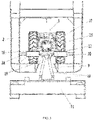
- the cargo vehicle 31 comprises a cargo vehicle bogie 3, a suspension device 10 connected under the cargo vehicle bogie 3, as well as a goods loading device integrated spreader 11 connected under the suspension device 10.
- a lower end of the goods loading device integrated spreader 11 is connected to the goods loading device 33.
- the present embodiment adopts a super-capacitor power supply mode.
- the cargo vehicle bogie 3 comprises a bogie frame 12 that is in a welded structure.
- a front end and a rear end of the bogie frame 12 are connected with two gearboxes 13 by welding, respectively, and each of the gearboxes 13 is symmetrically provided with two output shafts 14 on left and right sides thereof, and a travelling wheel 15 is mounted on each of the output shafts 14.
- the cargo vehicle bogie 3 runs on a lower surface of the inner cavity of the rail beam 2 by means of four travelling wheels 15.
- the front and rear ends of the two gearboxes 13 are connected to two frame intermediate connections 16 by bolts respectively, and the front and rear ends of the two frame intermediate connections 16 are connected by bolts with housings of two traction electric motors 17 that control the cargo vehicle bogie 3 to run.
- a left side and a right side of the housing of each of the traction electric motors 17 are symmetrically welded with two guide wheel mounting seats 18 on a lower portion thereof, and guide wheels 19 are mounted on the two guide wheel mounting seats 18 respectively.
- Guide rails 20 are provided on left and right side walls of the inner cavity of the rail beams 2 respectively, and the two guide wheels 19 move back and forth along the two guide rails 20, respectively.
- Each of the travelling wheels 15 and guide wheels 19 adopts rubber tires.
- a lower end of the bogie frame 12 is connected with the goods loading device integrated spreader 11 via the suspension device 10, and a lower end of the goods loading device integrated spreader 11 is connected to the goods loading device 33.
- the four cargo vehicle bogies 3 travel on the two rail beams 2, thereby driving the two goods loading devices 33 suspended under the four cargo vehicle bogies 3 to move along a direction of the rail beams 2.
- the transportation of the goods loading device 33 can be easily achieved through electric control.
- the four travelling wheels 15 of each cargo vehicle bogie 3 guarantees a steady travel on the rail beam 2, and the four guide wheels 19 of each cargo vehicle bogie 3 move back and forth along the guide rails 20 to effect the transportation of the goods loading device 33.
- the guide wheels 19 are provided to ensure that the cargo vehicle bogie 3 can steer steadily. All the travelling wheels 15 and the guide wheels 19 adopt rubber tires, so that an effect of shock absorption can be achieved when the cargo vehicle bogie 3 runs.
- the rail system 1 may be disposed in isolation strips, and multiple cargo vehicles 31 run on the two rail beams 2 in directions opposite to each other, respectively. Therefore, the air space is put into sufficient utilization, and no effect will be exerted on ground operations within the port, thus existing resources of docks can be utilized sufficiently for automation reformation, and problems such as dock congestion, lack of space and transport inefficiency can be solved. Thereby high-efficiency, low-cost and environment-friendly goods loading device quick and intelligent transport can be achieved, and meanwhile the transport system is simply structured, secure and reliable.
- the mounted rail beams 2 and the four cargo vehicle bogies 3 have a simple and compact structure without occupying extra space, and the structure of the rail beams 2 is also simple and makes it convenient for the cargo vehicle bogies 3 to move securely thereon.
- the rail beam 2 may further be in a C-shaped channel steel structure, which also falls within the protection scope of the present invention.
- a structure according to a second embodiment of the present invention comprises a rail system 1 comprising a rail pillar 30 and two rail beams 2.
- a lower surface of an upper portion of the rail pillar 30 is bilaterally symmetrically provided with two C-shaped rail grooves 8, and the two rail grooves 8 run through from a front end to a rear end of the rail system 1.
- Two rail beams 2 are mounted within the two rail grooves 8.
- the rail system 1 may be conveniently and stably disposed in isolation strips.
- the rail beams 2 are of a thin-walled steel box-type structure.
- a lower surface of the rail beams 2 is provided with an opening 9 extending through from a front end to a rear end thereof, and inner cavities of the two rail beams 2 are provided with multiple cargo vehicles 31 that are movable within the rail beams 2.
- the inner cavity of each of the rail beams 2 is provided with two cargo vehicles 31 which are supported at a lower surface of the inner cavity of the rail beams 2.
- the cargo vehicle 31 comprises a cargo vehicle bogie 3, a suspension device 10 connected under the cargo vehicle bogie 3, as well as a goods loading device integrated spreader 11 connected under the suspension device 10.
- a lower end of the goods loading device integrated spreader 11 is connected with the goods loading device 33.
- the present embodiment adopts a super-capacitor power supply mode.
- the cargo vehicle bogie 3 comprises a bogie frame 12 that is in a welded structure.
- a front end and a rear end of the bogie frame 12 are connected with two gearboxes 13 by welding respectively, and each of the gearboxes 13 is symmetrically provided with two output shafts 14 on left and right sides thereof, and a travelling wheel 15 is mounted on each of the output shafts 14.
- the cargo vehicle bogie 3 runs on the lower surface of the inner cavity of the rail beam 2 by means of four travelling wheels 15.
- Front and rear ends of the two gearboxes 13 are connected to two frame intermediate connections 16 by bolts respectively, and the front and rear ends of the two frame intermediate connections 16 are connected by bolts wtih housings of two traction electric motors 17 that control the cargo vehicle bogie 3 to run.
- a left side and a right side of the housing of each of the traction electric motors 17 are symmetrically welded with two guide wheel mounting seats 18 on a lower portion thereof, and guide wheels 19 are mounted on the two guide wheel mounting seats 18 respectively.
- Guide rails 20 are provided on left and right side walls of the inner cavity of the rail beams 2 respectively, and the two guide wheels 19 move back and forth along the two guide rails 20, respectively.
- Each of the travelling wheels 15 and guide wheels 19 adopts rubber tires.
- a lower end of the bogie frame 12 is connected to the goods loading device integrated spreader 11 via the suspension device 10 after passing through an opening 9, and a lower end of the goods loading device integrated spreader 11 is connected to the goods loading device 33.
- the suspension device 10 comprises a center pin 21 via which the suspension device 10 is connected to a lower end of the bogie frame 12.
- a lower end of the center pin 21 is connected with a connection seat 22 which is connected to two suspension arms 24 via two first spindles 23, and the suspension arm 24 is of a bending plate body.
- Lower ends of the two suspension arms 24 are connected to a mounting seat 26 via two second spindles 25, and the mounting seat 26 is connected to the goods loading device integrated spreader 11.
- the processor is in a signal communication with the traction electric motor 17 to control a start or stop of the traction electric motor 17.
- a working process and functions of the present embodiment is substantially same as those of the first embodiment, and thereby is not detailed here.
- the suspension device 10 as the foregoing structure, a force transmission by the cargo vehicle bogie 3 in three directions as X axis, Y axis and Z axis is achieved, and meanwhile, a relative movement between the goods loading device 33 and the cargo vehicle bogie 3 is satisfied.
- the structure according to the third embodiment comprises a rail system 1 comprising a rail pillar 30 and two rail beams 2.
- a lower surface of an upper portion of the rail pillar 30 is bilaterally symmetrically provided with two C-shaped rail grooves 8, and the two rail grooves 8 run through from a front end to a rear end of the rail system 1.
- Two rail beams 2 are mounted within the two rail grooves 8.
- the rail system 1 may be conveniently and stably disposed in isolation strips.
- the rail beams 2 are of a thin-walled steel box-type structure, and a lower surface of the rail beams 2 is provided with an opening 9 extending through from a front end to rear end thereof.
- Inner cavities of the two rail beams 2 are provided with multiple cargo vehicles 31 that are movable within the rail beams 2.
- the inner cavity of each of the rail beams 2 is provided with two cargo vehicles 31 which are supported at a lower surface of the inner cavity of the rail beam 2.
- the cargo vehicle 31 comprises a cargo vehicle bogie 3, a suspension device 10 connected under the cargo vehicle bogie 3, as well as a goods loading device integrated spreader 11 connected under the suspension device 10.
- the cargo vehicle bogie 3 comprises a bogie frame 12 that is in a welded structure.
- a front end and a rear end of the bogie frame 12 are connected with two gearboxes 13 by welding, respectively, and each of the gearboxes 13 is symmetrically provided with two output shafts 14 on left and right sides thereof, and a travelling wheel 15 is mounted on each of the output shafts 14.
- the cargo vehicle bogie 3 runs on a lower surface of the inner cavity of the rail beam 2 by means of four travelling wheels 15.
- the front and rear ends of the two gearboxes 13 are connected to two frame intermediate connections 16 by bolts respectively, and the front and rear ends of the two frame intermediate connections 16 are connected by bolts with housings of two traction electric motors 17 that control the cargo vehicle bogie 3 to run.
- a left side and a right side of the housing of each of the traction electric motors 17 are symmetrically welded with two guide wheel mounting seats 18 on a lower portion thereof, and guide wheels 19 are mounted on the two guide wheel mounting seats 18 respectively.
- Guide rails 20 are provided on left and right side walls of the inner cavity of the rail beams 2 respectively, and the two guide wheels 19 move back and forth along the two guide rails 20, respectively.
- Each of the travelling wheels 15 and guide wheels 19 adopts rubber tires.
- the suspension device 10 comprises a center pin 21 via which the suspension device 10 is connected to a lower end of the bogie frame 12.
- a lower end of the center pin 21 is connected with a connection seat 22 which is connected to two suspension arms 24 via two first spindles 23, and the suspension arm 24 is of a bending plate body.
- Lower ends of the two suspension arms 24 are connected to a mounting seat 26 via two second spindles 25, and the mounting seat 26 is connected to the goods loading device integrated spreader 11.
- the goods loading device integrated spreader 11 comprises a main structure 27 made of steel rails, and the mounting seat 26 is welded on the main structure 27.
- a front portion and a rear portion of the main structure 27 are respectively provided with an energy-absorption anti-collision device 29 so as to prevent an impact on the cargo vehicle bogie 3 and guarantee a security of the cargo vehicle bogie 3 and the working goods loading device 33 in case of emergency.
- the energy-absorption anti-collision device 29 may also be mounted on an end of the cargo vehicle bogie 3, or anywhere. The present invention is not limited in this regard, and any position where the energy-absorption anti-collision device 29 is mounted falls within the protection scope of the present invention.
- Safety cables are reserved between the cargo vehicle bogie 3 and the goods loading device 33, so as to guarantee the cargo vehicle 3 working securely, even if the cargo vehicle 3 is accidentally dropped in case of the suspension device 10 being out of work.
- a power supply system 28 is further included that supplies power to the cargo vehicle bogie 3.
- the power supply system 28 adopts a super-capacitor supply mode and is connected between the rail system 1 and the main structure 27 of the goods loading device integrated spreader 11.
- Embodiments of the present invention provide three structures of a transfer apparatus 32.
- a first transfer apparatus 32 at least comprises a conveyance mechanism, a grab mechanism and a lift mechanism.
- the grab mechanism places the goods loading device 33 on the conveyance mechanism.
- the conveyance mechanism transports the goods loading device 33 to the lift mechanism, and the lift mechanism lifts or lowers the goods loading device 33.
- the goods loading device 33 is loaded onto or unloaded from the cargo vehicle 31.
- a processor is communicatively connected with the conveyance mechanism, the grab mechanism and the lift mechanism.
- the conveyance mechanism at least comprises a first frame 71, a chain, a first group of rotation shafts 72 and a power outputting device.
- the first group of rotary shafts 72 is disposed on the first frame 71.
- Each rotation shaft of the first group of rotation shafts 72 is provided with gears on which the chain is fitted around to drive each rotation shaft of the first group of rotation shafts 72 to rotate, and the power output end of the power outputting device is connected to the chain to drive a rotation of the chain.
- the power outputting device is an electric motor ⁇
- the lift mechanism at least comprises a telescopic mechanism 73 and a base, and a telescopic end of the telescopic mechanism 73 is connected to the base.
- the base at least comprises a second frame 74 and a second group of rotation shafts 75.
- a telescopic end of the telescopic mechanism 73 is connected to the second frame 74, and the second group of rotation shafts 75 is disposed on the second frame 74.
- the structure of the base is further illustrated.
- the base further comprises at least a sensing element for sensing whether the goods loading device 33 reaches a predefined position, and the sensing element is disposed on the base.
- a signal output end of the sending element is connected to a signal input end of the processor.
- the sensing element comprises a displacement sensor and/or an infrared sensor.
- the grab mechanism at least comprises a telescopic arm 76, a first support rod 77, a second support rod 78, a first telescopic rod 79, a second telescopic rod 710, a third telescopic rod 711 and a spreader 712.
- a first end of the first support rod 77 is fixedly connected to the first frame 71,and a second end of the first support rod 77 is hinged to a first end of the second support rod 78.
- a second end of the second support rod 78 is hinged to the telescopic arm 76.
- a first end of the first telescopic rod 79 is fixedly connected to the first frame 71, and a second end of the first telescopic rod 79 is hinged to the second support rod 78.
- a first end of the second telescopic rod 710 is hinged to the first end of the second support rod 78, and a second end of the second telescopic rod 710 is hinged to a first end of the telescopic arm 76.
- a first end of the third telescopic rod 711 is fixedly connected to the first end of the telescopic arm 76, and a second end of the third telescopic rod 711 is fixedly connected to a second end of the telescopic arm 76.
- the second end of the telescopic arm 76 is connected to the spreader 712.
- the first telescopic rod 79, the second telescopic rod 710 and the third telescopic rod 711 may be pneumatic rods or hydraulic rods, and the present embodiment does not limit how the telescopic rod is driven.
- a second transfer apparatus 800 at least comprises a grab mechanism and a lift mechanism.
- the grab mechanism places the goods loading device on the lift mechanism, and the lift mechanism lifts or lowers the goods loading device.
- a processor is communicatively connected to the conveyance mechanism, the grab mechanism and the lift mechanism.
- the lift mechanism at least comprises a telescopic mechanism 83 and a base, and a telescopic end of the telescopic mechanism 83 is connected to the base.
- the base at least comprises a frame 84 and a support table 85.
- a telescopic end of the telescopic mechanism 83 is connected to the frame 84, and the support table 85 is disposed on the frame 84.
- the structure of the base is further illustrated.
- the base further comprises at least a sensing element for sensing whether the goods loading device reaches a predefined position, and the sensing element is disposed on the base.
- a signal output end of the sensing element is connected to a signal input end of the processor.
- the sensing element comprises a displacement sensor and/or an infrared sensor.
- the structure of the lift mechanism is further illustrated.
- the lift mechanism further comprises at least: a distance measuring element for sensing an extension amount of the telescopic mechanism 83.
- the distance measuring element is disposed on the telescopic mechanism 83 and/or the base.
- the grab mechanism at least comprises a telescopic arm 86, a first support rod 87, a second support rod 88, a first telescopic rod 89, a second telescopic rod 810, a third telescopic rod 811 and a spreader 812.
- a first end of the first support rod 87 is fixedly connected to the first frame 81, and a second end of the first support rod 87 is hinged to a first end of the second support rod 88.
- a second end of the second support rod 88 is hinged to the telescopic arm 86.
- a first end of the first telescopic rod 89 is fixedly connected to the first frame 81, and a second end of the first telescopic rod 89 is hinged to the second support rod 88.
- a first end of the second telescopic rod 810 is hinged to the first end of the second support rod 88, and a second end of the second telescopic rod 810 is hinged to a first end of the telescopic arm 86.
- a first end of the third telescopic rod 811 is fixedly connected to the first end of the telescopic arm 86, and a second end of the third telescopic rod 811 is fixedly connected to a second end of the telescopic arm 86.
- the second end of the telescopic arm 86 is connected to the spreader 812.
- the first telescopic rod 89, the second telescopic rod 810 and the third telescopic rod 811 may be pneumatic rods or hydraulic rods, and the present embodiment of the invention does not limit how the telescopic rod is driven.
- At least a controller is further provided.
- a signal input end of the controller is communicatively connected to signal output ends of the sensing element and the distance measuring element, and a signal output end of the controller is communicatively connected to signal input ends of the telescopic mechanism 83, the first telescopic rod 89, the second telescopic rod 810, the third telescopic rod 811 and the spreader 812.
- the controller controls the telescopic mechanism 83, the first telescopic rod 89, the second telescopic rod 810, the third telescopic rod 811 and the spreader 812 to work as required.
- a third transfer apparatus comprises an underframe 99, a lifting device 92, a lifting table 910, a lifting driving device 914, multiple travel wheels 93, a travel driving device 94, and a translation device 917.
- the lifting device 92 is connected between the underframe 99 and the lifting table 910;
- a surface of the lifting table 910 which is opposite to the lifting device 92 is provided with a first group of locks 911 and a second group of locks 912 which are snap-fasten to a bottom of the goods loading device 33.
- the second group of locks is located external to the first group of locks 911 and has a higher height than the first group of locks 911.
- Two ends of the surface of the lifting table 910 which is opposite to the lifting device 92 are provided with two protruding beams 913, and the second group of locks 912 is disposed on the two protruding beams 913.
- the first group of locks 911 and the second group of locks 912 consist of four embosses, respectively.
- the underframe 99 comprises at least two end beams 98, at least two side beams 97, a plurality of crossbeams and a bottom plate 916. Two ends of the at least two end beams 98 are connected to two ends of the at least two side beams 97, respectively.
- the plurality of crossbeams are disposed between the at least two end beams 98, and two ends thereof are connected to the at least two side beams 97, respectively.
- the bottom plate 916 is fixed onto the at least two end beams 98, the at least two side beams 97 and the plurality of crossbeams. In other embodiments, the bottom plate 916 may not be provided. Further, in the present embodiment, a travelling direction of the multiple travel wheels 93 is parallel to a length direction of the end beams 98.
- the travel wheel 93 may be provided as a rubber wheel or a universal wheel, and a kinetic energy of the transfer device may be provided by a super capacitor, and a quick charging pile may be arranged at a start position or a specified position.
- embodiments of the present invention at least may further comprise an alarm apparatus, and a signal input end of the alarm apparatus is communicatively connected to a signal output end of the processor.
- a goods loading device transfer operation procedure for transporting a goods loading device 33 from a port goods loading device dock to a railway, road or air logistics center and other goods loading device logistics center is as below:
- a goods loading device 33 may also be transported from a railway, road or air goods loading device logistics center to a port goods loading device dock, a specific operation procedure of which is in a reverse order with respect to the foregoing operation procedure and thereby is not illustrated here.
- a rail system 30 connecting various ports with railway and air logistics centers, and a processor controlling a transfer apparatus 32 to transfer a goods loading device 33 and controlling a cargo vehicle 31 to move on the rail system 30 after the goods loading device 33 is secured onto the cargo vehicle 31, a multimodal transport between ports and railway, air logistics centers is achieved.
- a multimodal transport between ports and railway, air logistics centers is achieved.
- road goods loading device transport trucks with the rail system, not only a transportation efficiency is increased, but also a pressure on the ground transportation is reduced and the environment is also protected.
- sky rail system 30 By means of a sky rail system 30 according to embodiments of the present invention, interconnecting and interworking between various goods loading device distribution centers may be achieved, and harmonious connection between rail, water, road and air logistics systems is realized, completely meeting "zero-distance transfer and seamless connection" requirements, and sufficiently releasing the ground transportation capacity.
- Embodiments of the present invention completely conform to the national strategy on vigorous development of multimodal transport and provide an overall solution for intelligent and efficient transfer of goods loading device multimodal transport.
Landscapes
- Engineering & Computer Science (AREA)
- Mechanical Engineering (AREA)
- Transportation (AREA)
- Business, Economics & Management (AREA)
- Economics (AREA)
- Aviation & Aerospace Engineering (AREA)
- General Physics & Mathematics (AREA)
- Physics & Mathematics (AREA)
- Tourism & Hospitality (AREA)
- Development Economics (AREA)
- Quality & Reliability (AREA)
- Strategic Management (AREA)
- Marketing (AREA)
- Human Resources & Organizations (AREA)
- General Business, Economics & Management (AREA)
- Entrepreneurship & Innovation (AREA)
- Theoretical Computer Science (AREA)
- Operations Research (AREA)
- Warehouses Or Storage Devices (AREA)
- Radar, Positioning & Navigation (AREA)
- Remote Sensing (AREA)
- Carriers, Traveling Bodies, And Overhead Traveling Cranes (AREA)
- Intermediate Stations On Conveyors (AREA)
- Fittings On The Vehicle Exterior For Carrying Loads, And Devices For Holding Or Mounting Articles (AREA)
- Automation & Control Theory (AREA)
Claims (7)
- Système d'interfonctionnement de transport multimodal, comprenant au moins :un système de rail (1, 30) ;un véhicule de fret (31) disposé, de manière mobile, sur une poutre de rail du système de rail (1, 30) ;un appareil de transfert (32) utilisé pour transférer un dispositif de chargement de marchandise (33) d'un outil de transport au véhicule de fret (31) et charger le dispositif de chargement de marchandise (33) sur le véhicule de fret (31) ou décharger le dispositif de chargement de marchandise (33) du véhicule de fret (31) et transporter le dispositif de chargement de marchandise (33) sur l'outil de transport ;un processeur raccordé au véhicule de fret (31) et à l'appareil de transfert (32) afin de commander l'appareil de transfert (32) pour qu'il transfère le dispositif de chargement de marchandise (33) et pour commander le véhicule de fret (31) pour qu'il se déplace sur la poutre de rail après que le dispositif de chargement de marchandise (33) a été fixé sur le véhicule de fret (31) ;dans lequel, étant donné que le dispositif de chargement de marchandise (33) doit être transféré, l'appareil de transfert (32) transfère le dispositif de chargement de marchandise (33) de l'outil de transport au véhicule de fret (31) et charge le dispositif de chargement de marchandise (33) sur le véhicule de fret (31), et le processeur commande le véhicule de fret (31) pour qu'il se déplace sur la poutre de rail, ou bien l'appareil de transfert (32) décharge le dispositif de chargement de marchandise (33) du véhicule de fret (31) et transporte le dispositif de chargement de marchandise (33) sur l'outil de transport ;caractérisé en ce que :chacun des véhicules de fret (31) comprend un bogie de véhicule de fret (3) supporté sur la surface inférieure de la cavité interne des poutres de rail (2), le bogie de véhicule de fret (3) comprenant un bâti de bogie (12) dont les extrémités avant et arrière sont respectivement raccordées avec des boîtes de vitesses (13), chacune des boîtes de vitesses (13) étant symétriquement prévue avec deux arbres de sortie (14) à gauche et à droite, une roue mobile (15) montée sur chacun des arbres de sortie (14), le bogie de véhicule de fret (3) circulant sur les poutres de rail (2) grâce à quatre roues mobiles (15), les extrémités avant et arrière des deux boîtes de vitesses (13) étant raccordées à deux raccordements intermédiaires de bâti (16) respectivement, les extrémités avant et arrière des deux raccordements intermédiaires de bâti (16) étant respectivement raccordées à deux moteurs électriques de traction (17) qui commandent le bogie de véhicule de fret (3) pour qu'il circule, une extrémité inférieure du bogie de véhicule de fret (3) étant raccordée à une entretoise intégrée de dispositif de chargement de marchandise (33) via un dispositif de suspension (10) après être passée par l'ouverture (9), une extrémité inférieure de l'entretoise intégrée de dispositif de chargement de marchandise (33) étant raccordée au dispositif de chargement de marchandise (33) ; le processeur est raccordé au moteur électrique de traction (17),dans lequel le système de rail (1) est monté de manière bilatéralement symétrique avec deux poutres de rail (2), les deux poutres de rail (2) étant respectivement prévues avec une pluralité de véhicules de fret (31) qui peuvent se déplacer sur ces dernières, le dispositif de chargement de marchandise (33) étant suspendu sur une extrémité inférieure de la pluralité de véhicules de fret (31) au-dessous de la poutre de rail de chaque côté,dans lequel les poutres de rail (2) sont réalisées avec une structure en forme de boîte, une surface inférieure des poutres de rail (2) étant prévue avec une ouverture (9) qui s'étend à travers une extrémité avant jusqu'à son extrémité arrière, le véhicule de fret (31) étant supporté sur une surface inférieure d'une cavité interne des poutres de rail (2).
- Système selon la revendication 1, dans lequel un côté gauche et un côté droit d'un boîtier de chacun des moteurs électriques de traction (17) sont raccordés, de manière symétrique, avec deux sièges de montage de roue de guidage (18) sur leur partie inférieure, les roues de guidage (19) étant montées sur les deux sièges de montage de roue de guidage (18) respectivement, les rails de guidage (20) étant prévus sur les parois latérales gauche et droite de l'ouverture (9) des poutres de rail (2) respectivement, les deux roues de guidage (18) se déplaçant le long des deux rails de guidage (20) respectivement.
- Système selon la revendication 2, dans lequel le dispositif de suspension (10) comprend une broche centrale (21), une extrémité supérieure de la broche centrale (21) étant raccordée à une extrémité inférieure du bâti de bogie (12), une extrémité inférieure de la broche centrale (21) étant raccordée avec un siège de raccordement (22) qui est raccordé à deux bras de suspension (24) via plusieurs premières fusées (23), les extrémités inférieures des deux bras de suspension (24) étant raccordées à un siège de montage (26) via plusieurs secondes fusées (25), le siège de montage (26) étant raccordé à l'entretoise intégrée (11) de dispositif de chargement de marchandise.
- Système selon la revendication 1, dans lequel l'appareil de transfert (32) comprend au moins : un mécanisme de transport, un mécanisme de préhension et un mécanisme de levage ; le mécanisme de préhension étant approprié pour placer le dispositif de chargement de marchandise (33) sur le mécanisme de transport ; le mécanisme de transport étant approprié pour transporter le dispositif de chargement de marchandise (33) jusqu'au mécanisme de levage ; le mécanisme de levage étant approprié pour lever ou abaisser le dispositif de chargement de marchandise (33) ; le dispositif de chargement de marchandise (33) étant approprié pour être chargé sur ou déchargé du véhicule de fret (31) ; le processeur étant raccordé, par communication, au mécanisme de transport, au mécanisme de préhension et au mécanisme de levage.
- Système selon la revendication 4, dans lequel le mécanisme de transport comprend au moins : un premier bâti (71), une chaîne, un premier groupe d'arbres de rotation (72) et un dispositif de sortie de puissance ; le premier groupe d'arbres de rotation (72) est disposé sur le premier bâti (71) ; chaque arbre de rotation du premier groupe d'arbres de rotation (72) est prévu avec des engrenages ; la chaîne est montée autour des engrenages pour entraîner chaque arbre de rotation du premier groupe d'arbres de rotation (72) à tourner ; une extrémité de sortie de puissance du dispositif de sortie de puissance est raccordée à la chaîne.
- Système selon la revendication 4, dans lequel le mécanisme de préhension comprend au moins : un bras télescopique (76), une première tige de support (77), une seconde tige de support (78), une première tige télescopique (79), une deuxième tige télescopique (710), une troisième tige télescopique (711) et une entretoise (712) ; une première extrémité de la première tige de support (77) est raccordée, de manière fixe, au premier bâti (71), et une seconde extrémité de la première tige de support (77) est articulée par rapport à une première extrémité de la seconde tige de support (78) ; une seconde extrémité de la seconde tige de support (78) est articulée par rapport au bras télescopique (76) ; une première extrémité de la première tige télescopique (79) est raccordée, de manière fixe, au premier bâti (71), et une seconde extrémité de la première tige télescopique (79) est articulée par rapport à la seconde tige de support (78) ; une première extrémité de la deuxième tige télescopique (710) est articulée par rapport à la première extrémité de la seconde tige de support (78), et une seconde extrémité de la deuxième tige télescopique (710) est articulée par rapport à une première extrémité du bras télescopique (76) ; une première extrémité de la troisième tige télescopique (711) est raccordée, de manière fixe, à la première extrémité du bras télescopique (76), et une seconde extrémité de la troisième tige télescopique (711) est raccordée, de manière fixe, à une seconde extrémité du bras télescopique (76) ; la seconde extrémité du bras télescopique (76) est raccordée à l'entretoise (712).
- Système selon la revendication 1, dans lequel l'appareil de transfert (32) comprend : un sous-châssis (99), un dispositif de levage (92), une table de levage (910), un dispositif d'entraînement de levage (914), une pluralité de roues mobiles (93) et un dispositif d'entraînement de déplacement (94) ;le dispositif de levage (92) est raccordé entre le sous-châssis (99) et la table de levage (910) ;le dispositif d'entraînement de levage (914) est raccordé au dispositif de levage (92) pour entraîner le dispositif de levage (92) à lever ou abaisser la table de levage (910) ;la pluralité de roues mobiles (93) est fixée sous le sous-châssis (99) ;le dispositif d'entraînement de déplacement (94) est fixé sur le sous-châssis (99) et raccordé aux roues de déplacement (93) pour entraîner une rotation des roues mobiles (93) ;le processeur est raccordé, par communication, au dispositif d'entraînement de levage (914) et au dispositif d'entraînement de déplacement (94).
Applications Claiming Priority (3)
| Application Number | Priority Date | Filing Date | Title |
|---|---|---|---|
| CN201621160102.0U CN206486008U (zh) | 2016-10-24 | 2016-10-24 | 一种多式联运互通系统 |
| CN201610937619.4A CN106516779B (zh) | 2016-10-24 | 2016-10-24 | 一种多式联运互通系统 |
| PCT/CN2017/094307 WO2018076834A1 (fr) | 2016-10-24 | 2017-07-25 | Système d'interfonctionnement de transport multimodal |
Publications (3)
| Publication Number | Publication Date |
|---|---|
| EP3428094A1 EP3428094A1 (fr) | 2019-01-16 |
| EP3428094A4 EP3428094A4 (fr) | 2019-11-27 |
| EP3428094B1 true EP3428094B1 (fr) | 2022-12-07 |
Family
ID=62023088
Family Applications (1)
| Application Number | Title | Priority Date | Filing Date |
|---|---|---|---|
| EP17865533.8A Active EP3428094B1 (fr) | 2016-10-24 | 2017-07-25 | Système d'interfonctionnement de transport multimodal |
Country Status (6)
| Country | Link |
|---|---|
| US (1) | US11097749B2 (fr) |
| EP (1) | EP3428094B1 (fr) |
| AU (1) | AU2017348144B2 (fr) |
| SG (1) | SG11201807460UA (fr) |
| WO (1) | WO2018076834A1 (fr) |
| ZA (1) | ZA201903264B (fr) |
Families Citing this family (6)
| Publication number | Priority date | Publication date | Assignee | Title |
|---|---|---|---|---|
| EP3428094B1 (fr) * | 2016-10-24 | 2022-12-07 | CRRC Yangtze Co., Ltd. | Système d'interfonctionnement de transport multimodal |
| CN111232639A (zh) * | 2020-03-17 | 2020-06-05 | 中建材凯盛机器人(上海)有限公司 | 装运一体式物料自动装车装置 |
| CN111453448B (zh) * | 2020-04-20 | 2022-02-18 | 中车长江车辆有限公司 | 一种铁路站场公铁联运模式转换的作业方法及系统 |
| CN111762233A (zh) * | 2020-06-03 | 2020-10-13 | 中铁武汉勘察设计研究院有限公司 | 铁水联运车辆交接安全防护系统及方法 |
| CN111891771A (zh) * | 2020-08-27 | 2020-11-06 | 北京品创智能科技有限公司 | 一种基于柔索的低功耗装载机器人 |
| CN112376393B (zh) * | 2020-12-02 | 2025-07-25 | 中铁第四勘察设计院集团有限公司 | 一种悬挂式单轨简支梁桥 |
Family Cites Families (16)
| Publication number | Priority date | Publication date | Assignee | Title |
|---|---|---|---|---|
| IL104578A (en) * | 1993-02-01 | 1995-07-31 | Mind E M S G Ltd | Transcontinental transport system |
| DE4332232C1 (de) * | 1993-09-22 | 1995-02-02 | Klaus Schroeder | Vorrichtung zum schnellen Umschlag von Transportbehältern |
| DE19533256A1 (de) * | 1995-09-08 | 1997-04-30 | Krupp Foerdertechnik Gmbh | Verfahren und Vorrichtung zum Umschlagen von Ladegut zwischen Schienen- und Straßenfahrzeugen |
| EP0831002A1 (fr) * | 1996-09-24 | 1998-03-25 | MANNESMANN Aktiengesellschaft | Dispositif pour transbordement horizontal de charges |
| DE29922538U1 (de) * | 1999-12-22 | 2001-05-03 | AUTEFA Automation GmbH, 86316 Friedberg | Verteileinrichtung für Güter |
| ITMI20020337A1 (it) * | 2002-02-20 | 2003-08-20 | Guido Porta | Metodo di trasporto ferroviario ed apparecchiatura per il carico e loscarico dei convogli |
| US8746153B2 (en) * | 2005-09-28 | 2014-06-10 | Leonard D. Barry | Go-between container transfer and system |
| US8585347B2 (en) * | 2007-06-26 | 2013-11-19 | Mi-Jack Products, Inc. | Hub and distribution system |
| CN201296509Y (zh) * | 2008-09-01 | 2009-08-26 | 高建飞 | 三轨重型积放输送设备 |
| JP5581048B2 (ja) * | 2009-12-21 | 2014-08-27 | 株式会社岡村製作所 | 物品搬送装置 |
| WO2014105862A1 (fr) * | 2012-12-28 | 2014-07-03 | Frost Tech Llc | Procédé et chariot de transport de grande capacité |
| ES2622469B2 (es) * | 2016-01-06 | 2018-03-08 | Antonio Marcos RUIZ VEGA | Procedimiento para el traslado de contenedores estandarizados entre un buque portacontenedores y un muelle |
| CN206486008U (zh) | 2016-10-24 | 2017-09-12 | 中车长江车辆有限公司 | 一种多式联运互通系统 |
| EP3428094B1 (fr) * | 2016-10-24 | 2022-12-07 | CRRC Yangtze Co., Ltd. | Système d'interfonctionnement de transport multimodal |
| WO2018076833A1 (fr) * | 2016-10-24 | 2018-05-03 | 中车长江车辆有限公司 | Système d'interconnexion de transport multimodal de type à enfourcher |
| CN106516779B (zh) * | 2016-10-24 | 2018-01-23 | 中车长江车辆有限公司 | 一种多式联运互通系统 |
-
2017
- 2017-07-25 EP EP17865533.8A patent/EP3428094B1/fr active Active
- 2017-07-25 AU AU2017348144A patent/AU2017348144B2/en active Active
- 2017-07-25 SG SG11201807460UA patent/SG11201807460UA/en unknown
- 2017-07-25 US US16/343,795 patent/US11097749B2/en active Active
- 2017-07-25 WO PCT/CN2017/094307 patent/WO2018076834A1/fr not_active Ceased
-
2019
- 2019-05-23 ZA ZA2019/03264A patent/ZA201903264B/en unknown
Also Published As
| Publication number | Publication date |
|---|---|
| AU2017348144B2 (en) | 2020-09-24 |
| US11097749B2 (en) | 2021-08-24 |
| WO2018076834A1 (fr) | 2018-05-03 |
| AU2017348144A1 (en) | 2019-06-06 |
| BR112018069264A2 (pt) | 2022-08-30 |
| ZA201903264B (en) | 2020-03-25 |
| EP3428094A1 (fr) | 2019-01-16 |
| US20190251510A1 (en) | 2019-08-15 |
| EP3428094A4 (fr) | 2019-11-27 |
| SG11201807460UA (en) | 2018-09-27 |
Similar Documents
| Publication | Publication Date | Title |
|---|---|---|
| EP3428093B1 (fr) | Système d'interconnexion de transport multimodal à base de voie ferroviaire aérien | |
| EP3428094B1 (fr) | Système d'interfonctionnement de transport multimodal | |
| CN113320994B (zh) | 一种自动集装箱存储、处理和转移系统 | |
| EP1847492B1 (fr) | Schéma d'arrangement d'un quai à containers et du procédé de déchargement/chargement des containers | |
| WO2024037246A1 (fr) | Appareil de chargement et de déchargement d'un système de transport de conteneur à suspension | |
| CN106516779B (zh) | 一种多式联运互通系统 | |
| CN106564764B (zh) | 一种多式联运互通系统 | |
| CN202116053U (zh) | 集装箱装卸自动化运输线 | |
| KR20030018003A (ko) | 조합된 레일/도로 수송용 철도 스테이션에서 레일 카의수송 및 비스듬한 하역을 위한 시스템과 그 사용 방법 | |
| CN109911786B (zh) | 一种物流节点站的集装器快速转运系统及方法 | |
| CN106794847B (zh) | 车厢附属装置以及货运车厢、货物转运设备和货物转运方法 | |
| CN107499849A (zh) | 一种集装箱输送装置及其输送方法 | |
| JP2022528449A (ja) | 多機能貨物移送車及び方法 | |
| CN106627603A (zh) | 一种多式联运互通控制系统 | |
| CN206486008U (zh) | 一种多式联运互通系统 | |
| CN109878402B (zh) | 一种用于铁路车厢运送的agv运输车 | |
| CN212332635U (zh) | 基于钢轮钢轨的集装箱悬挂式运输车辆 | |
| EP3428092B1 (fr) | Système d'interconnexion de transport multimodal de type à enfourcher | |
| HK1262421B (en) | Multimodal transport interworking system | |
| HK1262421A1 (en) | Multimodal transport interworking system | |
| CN209797331U (zh) | 一种物流节点站的集装器快速转运系统 | |
| CN206466734U (zh) | 一种多式联运互通系统 | |
| CN110127400B (zh) | 一种多式联运装卸设备及其装卸方法 | |
| CN121039016A (zh) | 船到岸水平集装箱转运系统 | |
| CN121404953A (zh) | 一种具有升降式支撑结构的高支腿集装箱搬运车 |
Legal Events
| Date | Code | Title | Description |
|---|---|---|---|
| STAA | Information on the status of an ep patent application or granted ep patent |
Free format text: STATUS: THE INTERNATIONAL PUBLICATION HAS BEEN MADE |
|
| PUAI | Public reference made under article 153(3) epc to a published international application that has entered the european phase |
Free format text: ORIGINAL CODE: 0009012 |
|
| STAA | Information on the status of an ep patent application or granted ep patent |
Free format text: STATUS: REQUEST FOR EXAMINATION WAS MADE |
|
| 17P | Request for examination filed |
Effective date: 20181012 |
|
| AK | Designated contracting states |
Kind code of ref document: A1 Designated state(s): AL AT BE BG CH CY CZ DE DK EE ES FI FR GB GR HR HU IE IS IT LI LT LU LV MC MK MT NL NO PL PT RO RS SE SI SK SM TR |
|
| AX | Request for extension of the european patent |
Extension state: BA ME |
|
| A4 | Supplementary search report drawn up and despatched |
Effective date: 20191025 |
|
| RIC1 | Information provided on ipc code assigned before grant |
Ipc: B61B 13/06 20060101ALI20191021BHEP Ipc: B61B 3/00 20060101ALI20191021BHEP Ipc: B61D 47/00 20060101ALI20191021BHEP Ipc: B65G 63/04 20060101AFI20191021BHEP |
|
| REG | Reference to a national code |
Ref country code: HK Ref legal event code: DE Ref document number: 1262421 Country of ref document: HK |
|
| DAV | Request for validation of the european patent (deleted) | ||
| DAX | Request for extension of the european patent (deleted) | ||
| STAA | Information on the status of an ep patent application or granted ep patent |
Free format text: STATUS: EXAMINATION IS IN PROGRESS |
|
| 17Q | First examination report despatched |
Effective date: 20210507 |
|
| GRAP | Despatch of communication of intention to grant a patent |
Free format text: ORIGINAL CODE: EPIDOSNIGR1 |
|
| STAA | Information on the status of an ep patent application or granted ep patent |
Free format text: STATUS: GRANT OF PATENT IS INTENDED |
|
| INTG | Intention to grant announced |
Effective date: 20220801 |
|
| GRAS | Grant fee paid |
Free format text: ORIGINAL CODE: EPIDOSNIGR3 |
|
| GRAA | (expected) grant |
Free format text: ORIGINAL CODE: 0009210 |
|
| STAA | Information on the status of an ep patent application or granted ep patent |
Free format text: STATUS: THE PATENT HAS BEEN GRANTED |
|
| AK | Designated contracting states |
Kind code of ref document: B1 Designated state(s): AL AT BE BG CH CY CZ DE DK EE ES FI FR GB GR HR HU IE IS IT LI LT LU LV MC MK MT NL NO PL PT RO RS SE SI SK SM TR |
|
| REG | Reference to a national code |
Ref country code: GB Ref legal event code: FG4D |
|
| REG | Reference to a national code |
Ref country code: CH Ref legal event code: EP Ref country code: AT Ref legal event code: REF Ref document number: 1536202 Country of ref document: AT Kind code of ref document: T Effective date: 20221215 |
|
| REG | Reference to a national code |
Ref country code: DE Ref legal event code: R096 Ref document number: 602017064484 Country of ref document: DE |
|
| REG | Reference to a national code |
Ref country code: IE Ref legal event code: FG4D |
|
| REG | Reference to a national code |
Ref country code: SE Ref legal event code: TRGR |
|
| REG | Reference to a national code |
Ref country code: LT Ref legal event code: MG9D |
|
| REG | Reference to a national code |
Ref country code: NL Ref legal event code: MP Effective date: 20221207 |
|
| PG25 | Lapsed in a contracting state [announced via postgrant information from national office to epo] |
Ref country code: NO Free format text: LAPSE BECAUSE OF FAILURE TO SUBMIT A TRANSLATION OF THE DESCRIPTION OR TO PAY THE FEE WITHIN THE PRESCRIBED TIME-LIMIT Effective date: 20230307 Ref country code: LT Free format text: LAPSE BECAUSE OF FAILURE TO SUBMIT A TRANSLATION OF THE DESCRIPTION OR TO PAY THE FEE WITHIN THE PRESCRIBED TIME-LIMIT Effective date: 20221207 Ref country code: FI Free format text: LAPSE BECAUSE OF FAILURE TO SUBMIT A TRANSLATION OF THE DESCRIPTION OR TO PAY THE FEE WITHIN THE PRESCRIBED TIME-LIMIT Effective date: 20221207 Ref country code: ES Free format text: LAPSE BECAUSE OF FAILURE TO SUBMIT A TRANSLATION OF THE DESCRIPTION OR TO PAY THE FEE WITHIN THE PRESCRIBED TIME-LIMIT Effective date: 20221207 |
|
| REG | Reference to a national code |
Ref country code: AT Ref legal event code: MK05 Ref document number: 1536202 Country of ref document: AT Kind code of ref document: T Effective date: 20221207 |
|
| PG25 | Lapsed in a contracting state [announced via postgrant information from national office to epo] |
Ref country code: RS Free format text: LAPSE BECAUSE OF FAILURE TO SUBMIT A TRANSLATION OF THE DESCRIPTION OR TO PAY THE FEE WITHIN THE PRESCRIBED TIME-LIMIT Effective date: 20221207 Ref country code: PL Free format text: LAPSE BECAUSE OF FAILURE TO SUBMIT A TRANSLATION OF THE DESCRIPTION OR TO PAY THE FEE WITHIN THE PRESCRIBED TIME-LIMIT Effective date: 20221207 Ref country code: LV Free format text: LAPSE BECAUSE OF FAILURE TO SUBMIT A TRANSLATION OF THE DESCRIPTION OR TO PAY THE FEE WITHIN THE PRESCRIBED TIME-LIMIT Effective date: 20221207 Ref country code: HR Free format text: LAPSE BECAUSE OF FAILURE TO SUBMIT A TRANSLATION OF THE DESCRIPTION OR TO PAY THE FEE WITHIN THE PRESCRIBED TIME-LIMIT Effective date: 20221207 Ref country code: GR Free format text: LAPSE BECAUSE OF FAILURE TO SUBMIT A TRANSLATION OF THE DESCRIPTION OR TO PAY THE FEE WITHIN THE PRESCRIBED TIME-LIMIT Effective date: 20230308 |
|
| P01 | Opt-out of the competence of the unified patent court (upc) registered |
Effective date: 20230515 |
|
| PG25 | Lapsed in a contracting state [announced via postgrant information from national office to epo] |
Ref country code: NL Free format text: LAPSE BECAUSE OF FAILURE TO SUBMIT A TRANSLATION OF THE DESCRIPTION OR TO PAY THE FEE WITHIN THE PRESCRIBED TIME-LIMIT Effective date: 20221207 |
|
| PG25 | Lapsed in a contracting state [announced via postgrant information from national office to epo] |
Ref country code: SM Free format text: LAPSE BECAUSE OF FAILURE TO SUBMIT A TRANSLATION OF THE DESCRIPTION OR TO PAY THE FEE WITHIN THE PRESCRIBED TIME-LIMIT Effective date: 20221207 Ref country code: RO Free format text: LAPSE BECAUSE OF FAILURE TO SUBMIT A TRANSLATION OF THE DESCRIPTION OR TO PAY THE FEE WITHIN THE PRESCRIBED TIME-LIMIT Effective date: 20221207 Ref country code: PT Free format text: LAPSE BECAUSE OF FAILURE TO SUBMIT A TRANSLATION OF THE DESCRIPTION OR TO PAY THE FEE WITHIN THE PRESCRIBED TIME-LIMIT Effective date: 20230410 Ref country code: EE Free format text: LAPSE BECAUSE OF FAILURE TO SUBMIT A TRANSLATION OF THE DESCRIPTION OR TO PAY THE FEE WITHIN THE PRESCRIBED TIME-LIMIT Effective date: 20221207 Ref country code: CZ Free format text: LAPSE BECAUSE OF FAILURE TO SUBMIT A TRANSLATION OF THE DESCRIPTION OR TO PAY THE FEE WITHIN THE PRESCRIBED TIME-LIMIT Effective date: 20221207 Ref country code: AT Free format text: LAPSE BECAUSE OF FAILURE TO SUBMIT A TRANSLATION OF THE DESCRIPTION OR TO PAY THE FEE WITHIN THE PRESCRIBED TIME-LIMIT Effective date: 20221207 |
|
| PG25 | Lapsed in a contracting state [announced via postgrant information from national office to epo] |
Ref country code: SK Free format text: LAPSE BECAUSE OF FAILURE TO SUBMIT A TRANSLATION OF THE DESCRIPTION OR TO PAY THE FEE WITHIN THE PRESCRIBED TIME-LIMIT Effective date: 20221207 Ref country code: IS Free format text: LAPSE BECAUSE OF FAILURE TO SUBMIT A TRANSLATION OF THE DESCRIPTION OR TO PAY THE FEE WITHIN THE PRESCRIBED TIME-LIMIT Effective date: 20230407 Ref country code: AL Free format text: LAPSE BECAUSE OF FAILURE TO SUBMIT A TRANSLATION OF THE DESCRIPTION OR TO PAY THE FEE WITHIN THE PRESCRIBED TIME-LIMIT Effective date: 20221207 |
|
| REG | Reference to a national code |
Ref country code: DE Ref legal event code: R097 Ref document number: 602017064484 Country of ref document: DE |
|
| PLBE | No opposition filed within time limit |
Free format text: ORIGINAL CODE: 0009261 |
|
| STAA | Information on the status of an ep patent application or granted ep patent |
Free format text: STATUS: NO OPPOSITION FILED WITHIN TIME LIMIT |
|
| PG25 | Lapsed in a contracting state [announced via postgrant information from national office to epo] |
Ref country code: DK Free format text: LAPSE BECAUSE OF FAILURE TO SUBMIT A TRANSLATION OF THE DESCRIPTION OR TO PAY THE FEE WITHIN THE PRESCRIBED TIME-LIMIT Effective date: 20221207 |
|
| 26N | No opposition filed |
Effective date: 20230908 |
|
| PG25 | Lapsed in a contracting state [announced via postgrant information from national office to epo] |
Ref country code: SI Free format text: LAPSE BECAUSE OF FAILURE TO SUBMIT A TRANSLATION OF THE DESCRIPTION OR TO PAY THE FEE WITHIN THE PRESCRIBED TIME-LIMIT Effective date: 20221207 |
|
| PG25 | Lapsed in a contracting state [announced via postgrant information from national office to epo] |
Ref country code: MC Free format text: LAPSE BECAUSE OF FAILURE TO SUBMIT A TRANSLATION OF THE DESCRIPTION OR TO PAY THE FEE WITHIN THE PRESCRIBED TIME-LIMIT Effective date: 20221207 |
|
| PG25 | Lapsed in a contracting state [announced via postgrant information from national office to epo] |
Ref country code: MC Free format text: LAPSE BECAUSE OF FAILURE TO SUBMIT A TRANSLATION OF THE DESCRIPTION OR TO PAY THE FEE WITHIN THE PRESCRIBED TIME-LIMIT Effective date: 20221207 |
|
| PG25 | Lapsed in a contracting state [announced via postgrant information from national office to epo] |
Ref country code: LU Free format text: LAPSE BECAUSE OF NON-PAYMENT OF DUE FEES Effective date: 20230725 |
|
| PG25 | Lapsed in a contracting state [announced via postgrant information from national office to epo] |
Ref country code: LU Free format text: LAPSE BECAUSE OF NON-PAYMENT OF DUE FEES Effective date: 20230725 |
|
| REG | Reference to a national code |
Ref country code: IE Ref legal event code: MM4A |
|
| PG25 | Lapsed in a contracting state [announced via postgrant information from national office to epo] |
Ref country code: IT Free format text: LAPSE BECAUSE OF FAILURE TO SUBMIT A TRANSLATION OF THE DESCRIPTION OR TO PAY THE FEE WITHIN THE PRESCRIBED TIME-LIMIT Effective date: 20221207 |
|
| PG25 | Lapsed in a contracting state [announced via postgrant information from national office to epo] |
Ref country code: IE Free format text: LAPSE BECAUSE OF NON-PAYMENT OF DUE FEES Effective date: 20230725 |
|
| PG25 | Lapsed in a contracting state [announced via postgrant information from national office to epo] |
Ref country code: IE Free format text: LAPSE BECAUSE OF NON-PAYMENT OF DUE FEES Effective date: 20230725 |
|
| PG25 | Lapsed in a contracting state [announced via postgrant information from national office to epo] |
Ref country code: BG Free format text: LAPSE BECAUSE OF FAILURE TO SUBMIT A TRANSLATION OF THE DESCRIPTION OR TO PAY THE FEE WITHIN THE PRESCRIBED TIME-LIMIT Effective date: 20221207 |
|
| PG25 | Lapsed in a contracting state [announced via postgrant information from national office to epo] |
Ref country code: BG Free format text: LAPSE BECAUSE OF FAILURE TO SUBMIT A TRANSLATION OF THE DESCRIPTION OR TO PAY THE FEE WITHIN THE PRESCRIBED TIME-LIMIT Effective date: 20221207 |
|
| PG25 | Lapsed in a contracting state [announced via postgrant information from national office to epo] |
Ref country code: CY Free format text: LAPSE BECAUSE OF FAILURE TO SUBMIT A TRANSLATION OF THE DESCRIPTION OR TO PAY THE FEE WITHIN THE PRESCRIBED TIME-LIMIT; INVALID AB INITIO Effective date: 20170725 |
|
| PG25 | Lapsed in a contracting state [announced via postgrant information from national office to epo] |
Ref country code: HU Free format text: LAPSE BECAUSE OF FAILURE TO SUBMIT A TRANSLATION OF THE DESCRIPTION OR TO PAY THE FEE WITHIN THE PRESCRIBED TIME-LIMIT; INVALID AB INITIO Effective date: 20170725 |
|
| PGFP | Annual fee paid to national office [announced via postgrant information from national office to epo] |
Ref country code: DE Payment date: 20250711 Year of fee payment: 9 |
|
| PGFP | Annual fee paid to national office [announced via postgrant information from national office to epo] |
Ref country code: BE Payment date: 20250724 Year of fee payment: 9 Ref country code: GB Payment date: 20250723 Year of fee payment: 9 |
|
| PGFP | Annual fee paid to national office [announced via postgrant information from national office to epo] |
Ref country code: FR Payment date: 20250730 Year of fee payment: 9 |
|
| PGFP | Annual fee paid to national office [announced via postgrant information from national office to epo] |
Ref country code: SE Payment date: 20250729 Year of fee payment: 9 Ref country code: CH Payment date: 20250801 Year of fee payment: 9 |
|
| PG25 | Lapsed in a contracting state [announced via postgrant information from national office to epo] |
Ref country code: TR Free format text: LAPSE BECAUSE OF FAILURE TO SUBMIT A TRANSLATION OF THE DESCRIPTION OR TO PAY THE FEE WITHIN THE PRESCRIBED TIME-LIMIT Effective date: 20221207 |