EP3428358B1 - Dämmstoffhalter - Google Patents
Dämmstoffhalter Download PDFInfo
- Publication number
- EP3428358B1 EP3428358B1 EP18181066.4A EP18181066A EP3428358B1 EP 3428358 B1 EP3428358 B1 EP 3428358B1 EP 18181066 A EP18181066 A EP 18181066A EP 3428358 B1 EP3428358 B1 EP 3428358B1
- Authority
- EP
- European Patent Office
- Prior art keywords
- insulation
- spirals
- insulation holder
- protuberances
- holder according
- Prior art date
- Legal status (The legal status is an assumption and is not a legal conclusion. Google has not performed a legal analysis and makes no representation as to the accuracy of the status listed.)
- Active
Links
Images



Classifications
-
- E—FIXED CONSTRUCTIONS
- E04—BUILDING
- E04B—GENERAL BUILDING CONSTRUCTIONS; WALLS, e.g. PARTITIONS; ROOFS; FLOORS; CEILINGS; INSULATION OR OTHER PROTECTION OF BUILDINGS
- E04B1/00—Constructions in general; Structures which are not restricted either to walls, e.g. partitions, or floors or ceilings or roofs
- E04B1/62—Insulation or other protection; Elements or use of specified material therefor
- E04B1/74—Heat, sound or noise insulation, absorption, or reflection; Other building methods affording favourable thermal or acoustical conditions, e.g. accumulating of heat within walls
- E04B1/76—Heat, sound or noise insulation, absorption, or reflection; Other building methods affording favourable thermal or acoustical conditions, e.g. accumulating of heat within walls specifically with respect to heat only
- E04B1/762—Exterior insulation of exterior walls
- E04B1/7629—Details of the mechanical connection of the insulation to the wall
Definitions
- the invention relates to an insulation holder with the features of the preamble of claim 1.
- insulation panels are used, which consist of a relatively soft insulation material that has an insulating effect.
- a typical insulation material is expanded polystyrene, as it is used in so-called thermal insulation composite systems.
- the insulation panels are usually attached to the anchoring base to be insulated, for example a concrete building wall, with the aid of insulation holders and fastening elements.
- a screw, a nail and / or a dowel for example, can be used as the fastening element.
- Anchoring grounds can, for example, be walls of buildings made of concrete, bricks or wooden panels.
- the insulation material is removed locally in the area of the insulation holder to be installed by milling or displaced by cutting and upsetting, so that a cylindrical receiving space is created, at the bottom of which the insulation holder rests on the insulation board.
- a suitable cylinder of the insulation a so-called "insulation washer”.
- a generic insulation holder is from the European patent application EP 2 639 374 A2 known.
- the insulation holder comprises a shaft with an insertion opening for a fastening element.
- the fastening element is a long-shaft dowel with which the insulation holder is doweled to the anchoring base.
- the insulation holder has an insulation plate with a circumferential cutting edge. With the cutting edge the insulation material moves with the rotation of the insulation material holder a turning tool about its longitudinal axis, for example by means of a cordless screwdriver, cut cylindrically so that the insulation holder can be set sunk.
- a profile is provided on the contact surface of the insulation plate with which the insulation plate rests on the insulation material after it has been set, which locally grinds or mills the insulation material when the insulation holder is turned around the longitudinal axis.
- the DE 20 2006 019 303 U1 discloses an insulation holder with the features of the preamble of claim 1.
- the object of the invention is to propose an insulation holder with improved assembly properties.
- the insulation holder according to the invention for fastening an insulation board to an anchoring base has a shaft with an insertion opening for receiving a fastening element with which the insulation holder can be fastened to the anchoring base.
- the fastening element can in particular be a screw for fastening in an anchoring base made of wood or a long shaft or nail dowel for fastening in concrete or masonry, whereby other fastening elements can also be combined with the insulation holder according to the invention.
- the insertion opening extends along a longitudinal axis of the insulation holder and is designed so that the fastening element can be at least partially inserted into the insertion opening.
- the fastening element After insertion, the fastening element is axially firmly connected to the insulation holder so that the insulation holder can be braced against the insulation board to be fastened by means of the fastening element. After the fastening element has been inserted, the fastening element can furthermore be rotatable with respect to the longitudinal axis relative to the insulation holder. So that the insulation holder can activate a sufficiently large area for the dissipation of forces with the relatively soft insulation materials without the insulation holder being pulled through the insulation board, the insulation holder has a disk-shaped insulation plate, which is arranged in a collar-like manner around the shaft of the insulation holder radially to the longitudinal axis . The insulation plate does not have to completely encompass the shaft.
- the insulation plate is designed in particular in the form of a circular ring-like disc surrounding the shaft.
- “Disk” does not mean that the insulation plate has to be completely flat, but it can also be curved or also have openings or incisions, the insulation plate in particular is flat and / or in particular forms a surface that is closed in axial projection.
- the diameter of the insulation plate is in particular several times, in particular more than 3 to 6 times larger than the diameter of the part of the fastening element that is used to fasten the fastening element in the anchoring base .
- the insulation plate also has a contact surface for contact with the insulation board during assembly and in the assembled state.
- the contact surface is arranged on the front side of the insulation plate in the insertion direction, that is to say on the side which is directed towards the insulation board for mounting the insulation holder.
- the "direction of insertion” is the direction in which the insulation holder penetrates the insulation board when it is countersunk.
- a profiling is arranged on the insulation plate, which protrudes axially from the contact surface in the direction of the longitudinal axis and in the insertion direction.
- the profiling is designed in such a way that it is suitable for local removal of insulation material under the insulation plate by milling, loosening and / or grinding parts of the insulation board when sunk when turning the insulation plate around the longitudinal axis using a rotary tool.
- the profiling is formed by local elevations.
- the insulation holder can be rotated either directly by a rotary tool and / or indirectly via a rotary tool acting on the fastening means. If the insulation holder is rotated indirectly, the fastening means must be rotatably coupled to the insulation holder, for example via a form-fitting connection.
- a form-fitting connection can be implemented, for example, by a screw with a hexagonal head which engages in a corresponding insertion opening. Alternatively, the fastening element can be held in a clamping manner in the insertion opening.
- the distance between adjacent elevations is greater than the diameter of the adjacent elevations. If the adjacent elevations have different diameters, the smaller of the diameters is decisive. In order to achieve effective removal, this criterion must be met for at least one third, in particular at least two thirds and in particular at least 90% of the elevations that are arranged on the contact surface. In particular, the diameter of a protrusion is not smaller than 1 mm.
- the inventive Design is based on the knowledge that the insulation material is only removed effectively when the distance between two elevations is sufficiently large so that the material removed can be moved under the insulation plate in order to at least partially grind and distribute it. By distributing and grinding the removed insulation material acts in the manner of a sliding or ball bearing between the contact surface and the insulation material, which greatly reduces the torque required for screwing in compared to an insulation disk lying flat against the insulation material.
- the elevations are knob-like, so that the elevations remove the insulating material particularly efficiently and effectively with a low torque.
- the knob-like elevations can in particular have the shape of a cylinder, a hemisphere or a truncated cone.
- “knob-like” means a local elevation, the dimensions of which in the radial direction, in the circumferential direction and in the longitudinal direction are of the same order of magnitude.
- the elevation does not have to be symmetrical, in particular not rotationally symmetrical, but can have any shape.
- the elevations are not evenly distributed on the contact surface. This means that the number of elevations per unit area of the contact surface varies at least locally in the contact surface.
- At least two adjacent elevations have different diameters, which enables particularly efficient removal of the insulation material and good distribution of the removed insulation material under the insulation plate.
- the radial extent of the elevations increases in the direction from the shaft to the circumference of the insulation plate.
- “Radial expansion” means the dimension of an elevation with which the elevation extends radially to the longitudinal axis of the insulation holder.
- the distance between two adjacent elevations increases in the direction from the shaft to the circumference of the insulation plate.
- this increase does not have to take place exclusively in the radial direction.
- the distance between adjacent elevations in the direction from the shaft to the circumference of the insulating plate also increases when the elevations are arranged, for example, in the form of a spiral on the contact surface of the insulating plate.
- the axial height of the elevations can also vary over the contact surface and / or increase or decrease in the radial direction. In particular, however, the height of the elevations above the contact surface is constant, so that the insulation material under the plate is removed evenly. In order to achieve good removal of the insulation material, the height of an elevation is in particular at least 1.0 mm, in particular at least 1.5 mm.
- the elevations between the insertion opening and the circumference of the insulation plate are arranged in a spiral, that is, the elevations are arranged in such a way that several of the elevations together form parts of at least one spiral that runs between the insertion opening and the circumference of the insulation plate extends outward around the longitudinal axis.
- a continuous spiral has to be visibly perceptible, but that the spirally arranged elevations lie together on a spiral connecting line, which is referred to below as a "spiral".
- a spiral is formed by at least four elevations.
- a plurality of spirals are preferably formed by the elevations, it being preferred that each of the elevations is part of at least two spirals.
- the arrangement of the groups in the form of one or more spirals has been found to be particularly advantageous because, surprisingly, this configuration means that the removal takes place even at a low torque.
- this is the case when a first number of spirals has a first direction of rotation and a second number of spirals has a second direction of rotation, the two directions of rotation, relative to the longitudinal axis of the insulation holder, being directed opposite one another, as in a preferred embodiment of the insulation holder according to the invention is the case.
- the number of first spirals with the first direction of rotation preferably differs from the number of second spirals with the second direction of rotation.
- the number of first spirals forms a certain ratio with the number of second spirals, which in a particularly preferred embodiment of the insulation age according to the invention corresponds to the ratio of two numbers in the Fibonacci sequence.
- the ratio of two consecutive numbers of the Fibonacci sequence is formed, in particular the numbers 8 and 13 and / or the numbers 13 and 21. If more than two types of spirals are formed, the number of spirals corresponds in particular to a further type also a number in the Fibonacci sequence.
- each of the elevations is part of at least two spirals, these two spirals having directions of rotation which are opposite to one another with respect to the longitudinal axis.
- a cutting device for cutting into the insulating material is arranged on the circumference of the insulating material plate, protruding from the insulating material plate in the direction in which the insulating material holder is inserted into an insulating material.
- the cutting device is formed by a circumferential wall-like and uninterrupted cutting edge.
- the axial height of the cutting device is greater than the axial height of the elevations, in particular the cutting device is at least 1.25 times greater than the height of the highest elevation.
- a cutting device designed in this way cuts the insulation material on the circumference of the insulation material plate, to be precise before the elevations that follow due to their lower height can mill off the insulation material. This creates a neatly cut cylinder wall into which, after the insulation holder has been sunk, an insulation washer can be precisely fitted.
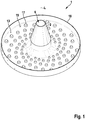
- an insulation holder 1 according to the invention is shown, with which an insulation board can be attached to an anchoring base (both not shown). All figures are drawn to scale.
- the insulation holder 1 has a shaft 2 which extends along a longitudinal axis L of the insulation holder 1.
- the shaft 2 comprises a frustoconical front part 3 which extends from a front end 4 of the insulation holder 1 in the insertion direction E of the insulation holder 1 into an insulation material to a rear, cylindrical part 5 of the shaft 2 (cf. Figure 2 ).
- Both parts 3, 5 of the shaft 2 form a sleeve with an insertion opening 6, which also extends along the longitudinal axis L.
- the insertion opening 6 serves to receive a fastening element (not shown) with which the insulation holder 1 can be fastened to an anchoring base, in the exemplary embodiment a wood screw with a countersunk head for screwing into a wooden structure on which an insulation board is to be fastened (not shown).
- the insertion opening 6 is formed by a front and a rear cylinder section 7, 8 in the front part 3 and in the rear part 5 of the shaft 2, which differ in diameter, and are connected by a conical transition 9, which is at the front end of the rear Part 5 is formed.
- a countersunk screw can be inserted into the insertion opening 6 in the insertion direction E until the screw head rests on the conical transition 9.
- Axial ribs 10 and circumferential ribs 11 are arranged in the rear cylinder section 8.
- the axial ribs 10 center and hold the screw head by clamping it in a rotationally fixed manner with the insulation holder 1, while the circumferential ribs 11 engage behind the screw head and hold it axially with the insulation holder 1 in a form-fitting manner.
- the holding plate 13 also has depressions on its outer surface 14, into which a setting tool can engage in a form-fitting manner (not shown).
- the rear end 12 of the insulation holder 1 is formed by the rear end of the shaft 2 and the rear end of a disk-shaped insulation plate 13, which is integrally connected to the shaft 2 and made of plastic together with the shaft 2 by injection molding.
- the insulation plate 13 has the rear end of the The outer surface 14 forming the insulation material holder 1 and a flat, flat contact surface 15 which is at the front in the insertion direction E and which is directed towards the insulation board during assembly.
- the insulation plate 13 has no openings in the plate level, but it is closed over a large area.
- the insulation plate 13 On the outer circumference of the insulation plate 13 there is also a cutting device 16 protruding in the insertion direction E in the form of a wall-like cutting edge which, with the contact surface 15, forms a cylindrical receiving space for insulation material and whose axial height is 4.5 mm. So that the insulation holder 1 according to the invention can be set sunk in an insulation material, the cutting device 16 cuts the insulation material in a circular manner when the insulation material holder 1 is rotated, which creates a cleanly cut, cylindrical outer surface in the insulation material.
- the elevations 17 not only mill the insulation material, but they grind or crush and distribute the insulation material under the insulation plate 13, so that the milled insulation material between the insulation plate 13 and the insulation board forms a friction-reducing intermediate layer, with individual particles of the milled insulation material being a kind of spherical or Form plain bearings.
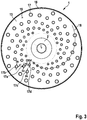
- the elevations 17 are arranged such that the distance a1 between a first elevation 17a and a second elevation 17b adjacent to this elevation 17a is greater than the diameter Da, Db of these elevations 17a, 17b (cf. Figure 3 ).
- the two adjacent elevations 17a, 17b have different diameters Da, Db, the distance a1 being greater than the smaller diameter Da of these elevations 17a, 17b, which is 1.2 mm.
- the elevations 17 all have the same axial height H of 1.5 mm (cf. Figure 2 ). According to the invention, the distance a between two adjacent elevations 17 increases in the direction from the shaft 2 to the circumference of the insulation plate 13. Likewise, the radial extension of the elevations 7 increases in the direction from the shaft 2 to the circumference of the insulation plate. So is in Figure 3 the distance a2 between a radially inner fourth elevation 17d to the first elevation 17a is smaller than the distance a1.
- the elevations 17 are not uniform on the contact surface 15 of the insulating plate 13 distributed, but in such a way that several of the elevations 17 together form a spiral 18.
- the first elevation 17a lies with a third elevation 17c on a first spiral 18a (cf. Figure 4a ), which extends outward around the longitudinal axis L between the insertion opening 6 and the circumference of the insulating plate 13.
- the first elevation 17a lies on a second spiral 18b, on which the second elevation 17b and a fourth elevation 17d also lie (cf. Figure 4b ).
- the second elevation 17b and the third elevation 17c together form a third spiral 18c (cf. Figure 4c ).
- the elevations 17 thus form first and second spirals 18a, 18b which, with respect to the longitudinal axis L, have opposite directions of rotation D1, D2. This also applies to the first spirals 18a and the third spirals 18c.
- the first spiral 18a has a first direction of rotation D1, which is opposite to the direction of rotation D2 of the second spiral 18b and the direction of rotation D3 of the third spiral 18c.
- the plurality of elevations 17 each form a plurality of first, second and third spirals 18a, 18b, 18c.
- the differently designed spirals 18 also differ in the number in which they are arranged on the insulation plate 13.
- the elevations 17 form eight first spirals 18a, thirteen third spirals 18c and twenty-one second spirals 18b.
- the numbers 8, 13 and 21 are consecutive numbers in the Fibonacci sequence.
- the insulation holder 1 according to the invention is characterized by a low torque required for deep setting in an insulation, which is advantageous for a user in terms of handling.
- As an injection-molded part it can be manufactured inexpensively in one piece, is robust and easy to use.
Landscapes
- Physics & Mathematics (AREA)
- Engineering & Computer Science (AREA)
- Architecture (AREA)
- Acoustics & Sound (AREA)
- Electromagnetism (AREA)
- Civil Engineering (AREA)
- Structural Engineering (AREA)
- Processing Of Stones Or Stones Resemblance Materials (AREA)
- Insulating Bodies (AREA)
- Connection Of Plates (AREA)
Description
- Die Erfindung betrifft einen Dämmstoffhalter mit den Merkmalen des Oberbegriffs des Anspruchs 1.
- Zur Wärmedämmung von Gebäuden werden Dämmstoffplatten verwendet, die aus einem relativ weichen Dämmstoff bestehen, der isolierend wirkt. Ein typischer Dämmstoff ist expandiertes Polystyrol, wie es in sogenannten Wärmedämmverbundsystemen verwendet wird. Die Dämmstoffplatten werden üblicherweise mit Hilfe von Dämmstoffhaltern und Befestigungselementen an dem zu dämmenden Verankerungsgrund, beispielsweise einer Gebäudewand aus Beton, befestigt. Abhängig vom Verankerungsgrund kann als Befestigungselement beispielsweise eine Schraube, ein Nagel und/oder ein Dübel verwendet werden. Verankerungsgründe können beispielsweise Wände von Gebäuden aus Beton, Mauersteinen oder Holztafeln sein. Diese Aufzählungen sind beispielhaft und nicht abschließend. Um eine möglichst gute Wärmedämmung ohne Kältebrücken zu erreichen, können geeignete Dämmstoffhalter in der Dämmstoffplatte versenkt gesetzt werden. Hierzu wird in einem zusätzlichen Schritt oder beim Montieren des Dämmstoffhalters der Dämmstoff lokal im Bereich des zu montierenden Dämmstoffhalters durch Fräsen entfernt oder durch Einschneiden und Stauchen verdrängt, sodass ein zylinderförmiger Aufnahmeraum entsteht, an dessen Boden der Dämmstoffhalter an der Dämmstoffplatte anliegt. Nach dem Montieren des Dämmstoffhalters wird der übrige Teil des Aufnahmeraums durch ein passendes Zylinderstück des Dämmstoffs, einer sogenannten "Dämmstoffrondelle", verschlossen.
- Ein gattungsgemäßer Dämmstoffhalter ist aus der europäischen Patentanmeldung
EP 2 639 374 A2 bekannt. Der Dämmstoffhalter umfasst einen Schaft mit einer Einführöffnung für ein Befestigungselement. Das Befestigungselement ist ein Langschaftdübel, mit dem der Dämmstoffhalter am Verankerungsgrund verdübelt ist. Der Dämmstoffhalter weist einen Dämmstoffteller auf, mit einer umlaufenden Schneide am Umfang. Mit der Schneide wird der Dämmstoff beim Drehen des Dämmstoffhalters mit einem Drehwerkzeug um seine Längsachse, beispielsweise mittels eines Akkuschraubers, zylindrisch eingeschnitten, so dass der Dämmstoffhalter versenkt gesetzt werden kann. Um das Einbringen des Dämmstoffhalters in die Dämmplatte zu erleichtern, ist an der Anlagefläche des Dämmstofftellers, mit der der Dämmstoffteller nach dem Setzen am Dämmstoff anliegt, eine Profilierung vorgesehen, die den Dämmstoff beim Drehen des Dämmstoffhalters um die Längsachse lokal zermahlt beziehungsweise zerfräst. - Die
DE 20 2006 019 303 U1 offenbart einen Dämmstoffhalter mit den Merkmalen des Oberbegriffs des Anspruchs 1. - Aufgabe der Erfindung ist, einen Dämmstoffhalter mit verbesserten Montageeigenschaften vorzuschlagen.
- Diese Aufgabe wird erfindungsgemäß durch einen Dämmstoffhalter mit den Merkmalen des Anspruchs 1 gelöst. Der erfindungsgemäße Dämmstoffhalter zur Befestigung einer Dämmstoffplatte an einem Verankerungsgrund weist einen Schaft mit einer Einführöffnung zur Aufnahme eines Befestigungselements auf, mit dem der Dämmstoffhalter am Verankerungsgrund befestigt werden kann. Das Befestigungselement kann insbesondere eine Schraube zur Befestigung in einem Verankerungsgrund aus Holz oder ein Langschaft- oder Nageldübel zur Befestigung in Beton oder Mauerwerk sein, wobei auch andere Befestigungselemente mit dem erfindungsgemäßen Dämmstoffhalter kombiniert werden können. Die Einführöffnung erstreckt sich entlang einer Längsachse des Dämmstoffhalters und ist so gestaltet, dass das Befestigungselement zumindest teilweise in die Einführöffnung eingesteckt werden kann. Nach dem Einführen ist das Befestigungselement axial fest mit dem Dämmstoffhalter verbunden, sodass der Dämmstoffhalter mittels des Befestigungselements gegen die zu befestigende Dämmstoffplatte verspannt werden kann. Nach dem Einführen des Befestigungselements kann das Befestigungselement weiterhin bezüglich der Längsachse drehbar zum Dämmstoffhalter sein. Damit der Dämmstoffhalter bei den relativ weichen Dämmstoffen eine ausreichend große Fläche zur Ableitung von Kräften aktivieren kann, ohne dass der Dämmstoffhalter durch die Dämmstoffplatte durchgezogen wird, weist der Dämmstoffhalter einen scheibenförmigen Dämmstoffteller auf, der insbesondere bundartig radial zur Längsachse um den Schaft des Dämmstoffhalters angeordnet ist. Der Dämmstoffteller muss dabei den Schaft nicht vollständig umfassen. Der Dämmstoffteller ist insbesondere in Form einer kreisringartigen, den Schaft umfassenden Scheibe ausgebildet. "Scheibe" bedeutet nicht, dass der Dämmstoffteller komplett eben sein muss, sondern er kann auch gewölbt sein oder auch Öffnungen oder Einschnitte aufweisen, wobei der Dämmstoffteller insbesondere flächig eben ist und/oder insbesondere eine in axialer Projektion geschlossene Fläche bildet. Um einen möglichst guten Halt auch in weichen Dämmstoffen zu ermöglichen, ist der Durchmesser des Dämmstofftellers insbesondere um ein Mehrfaches, insbesondere um mehr als das 3- bis 6-fache größer als der Durchmesser des Teils des Befestigungselements, der zur Befestigung des Befestigungselements im Verankerungsgrund dient. Mit "Durchmesser" ist hier und im Folgenden, sofern nichts anderes erwähnt ist, der Durchmesser eines kreisrunden Querschnitts beziehungsweise eines einen nicht-kreisrunden Querschnitt umschreibenden Umkreises gemeint. Der Dämmstoffteller weist zudem eine Anlagefläche zur Anlage an der Dämmstoffplatte während der Montage und im montierten Zustand auf. Die Anlagefläche ist auf der in Einbringrichtung vorderen Seite des Dämmstofftellers angeordnet, also auf der Seite, die zur Montage des Dämmstoffhalters zur Dämmstoffplatte hin gerichtet ist. Die "Einbringrichtung" ist die Richtung, in die der Dämmstoffhalter beim versenkten Setzen in die Dämmstoffplatte eindringt. Am Dämmstoffteller ist eine Profilierung angeordnet, die von der Anlagefläche axial in Richtung der Längsachse und in Einbringrichtung absteht. Die Profilierung ist derart gestaltet, dass sie sich beim Drehen des Dämmstofftellers um die Längsachse mittels eines Drehwerkzeugs zum lokalen Entfernen von Dämmstoff unter dem Dämmstoffteller durch Abfräsen, Lösen, und/oder Zermahlen von Teilen der Dämmstoffplatte beim versenkten Setzen eignet. Die Profilierung wird durch lokale Erhöhungen gebildet. Der Dämmstoffhalter kann zum drehenden Fräsen entweder direkt durch ein Drehwerkzeug und/oder indirekt über ein auf das Befestigungsmittel wirkendes Drehwerkzeug gedreht werden. Wird der Dämmstoffhalter indirekt gedreht, so muss das Befestigungsmittel mit dem Dämmstoffhalter drehgekoppelt sein, beispielsweise über eine formschlüssige Verbindung. Eine formschlüssige Verbindung kann beispielsweise durch eine Schraube mit Sechskantkopf realisiert werden, die in eine korrespondierende Einführöffnung eingreift. Alternativ kann das Befestigungselement klemmend in der Einführöffnung gehalten sein.
- Erfindungsgemäß ist der Abstand zwischen benachbarten Erhöhungen größer als der Durchmesser der benachbarten Erhöhungen. Weisen die benachbarten Erhöhungen unterschiedliche Durchmesser auf, so ist der kleinere der Durchmesser maßgebend. Um einen effektiven Abtrag zu erreichen, muss dieses Kriterium bei mindestens einem Drittel, insbesondere bei mindestens zwei Drittel und insbesondere bei mindestens 90 % der Erhöhungen, die an der Anlagefläche angeordnet sind, erfüllt sein. Insbesondere ist der Durchmesser einer Erhöhung nicht kleiner als 1 mm. Die erfindungsgemäße Ausgestaltung beruht auf der Erkenntnis, dass ein Abtrag des Dämmstoffs nur dann effektiv erfolgt, wenn der Abstand zwischen zwei Erhöhungen ausreichend groß ist, damit das abgetragene Material unter dem Dämmstoffteller bewegt werden kann, um es zumindest teilweise zu zermahlen und zu verteilen. Durch das Verteilen und Zermahlen wirkt der abgetragene Dämmstoff in der Art eines Gleit- oder Kugellagers zwischen der Anlagefläche und dem Dämmstoff, wodurch das zum Eindrehen notwendige Drehmoment im Vergleich zu einem flächig am Dämmstoff anliegenden Dämmstoffteller stark reduziert ist.
- Insbesondere sind die Erhöhungen noppenartig ausgebildet, wodurch die Erhöhungen den Dämmstoff besonders effizient und effektiv bei geringem Drehmoment abtragen. Die noppenartigen Erhöhungen können insbesondere die Form eines Zylinders, einer Halbkugel oder eines Kegelstumpfs aufweisen. Allgemein ist mit "noppenartig" eine lokale Erhöhung gemeint, deren Abmessungen in radialer Richtung, in Umfangsrichtung und in Längsrichtung in der gleichen Größenordnung liegen. Die Erhöhung muss aber nicht symmetrisch, insbesondere nicht rotationssymmetrisch sein, sondern kann eine beliebige Gestalt aufweisen.
- Als besonders vorteilhaft hat sich herausgestellt, wenn die Erhöhungen, wie bei einer bevorzugten Ausgestaltungsform des erfindungsgemäßen Dämmstoffhalters vorgesehen, an der Anlagefläche nicht gleich verteilt sind. Das bedeutet, dass die Anzahl der Erhöhungen pro Flächeneinheit der Anlagefläche in der Anlagefläche zumindest lokal variiert.
- Zudem ist bevorzugt, dass zumindest zwei benachbarte Erhöhungen unterschiedliche Durchmesser aufweisen, was einen besonders effizienten Abtrag des Dämmstoffs und eine gute Verteilung des abgetragenen Dämmstoffs unter dem Dämmstoffteller ermöglicht.
- Bei einer weiteren bevorzugten Ausgestaltungsform des erfindungsgemäßen Dämmstoffhalters nimmt die radiale Ausdehnung der Erhöhungen in Richtung vom Schaft zum Umfang des Dämmstofftellers hin zu. Mit "radialer Ausdehnung" ist die Abmessung einer Erhöhung gemeint, mit der sich die Erhöhung radial zur Längsachse des Dämmstoffhalters erstreckt.
- Erfindungsgemäß nimmt der Abstand zwischen zwei benachbarten Erhöhungen in Richtung vom Schaft zum Umfang des Dämmstofftellers hin zu. Diese Zunahme muss aber nicht ausschließlich in radialer Richtung erfolgen.
- Beispielsweise nimmt der Abstand zwischen benachbarten Erhöhungen in Richtung vom Schaft zum Umfang des Dämmstofftellers auch dann zu, wenn die Erhöhungen beispielsweise in Form einer Spirale an der Anlagefläche des Dämmstofftellers angeordnet sind.
- Die axiale Höhe der Erhöhungen, also ihre Ausdehnung in Längsrichtung, kann ebenfalls über die Anlagefläche variieren und/oder in radialer Richtung zu- oder abnehmen. Insbesondere ist die Höhe der Erhöhungen über die Anlagefläche aber konstant, sodass es zu einem gleichmäßigen Abtrag des Dämmstoffs unter dem Teller kommt. Um einen guten Abtrag des Dämmstoffs zu erreichen, beträgt die Höhe einer Erhöhung insbesondere mindestens 1,0 mm, insbesondere mindestens 1,5 mm.
- Bei einer weiteren bevorzugten Ausgestaltungsform des erfindungsgemäßen Dämmstoffhalters sind die Erhöhungen zwischen der Einführöffnung und dem Umfang des Dämmstofftellers spiralförmig angeordnet, das heißt die Erhöhungen sind derart angeordnet, dass mehrere der Erhöhungen gemeinsam Teile mindestens einer Spirale bilden, die zwischen der Einführöffnung und dem Umfang des Dämmstofftellers nach außen um die Längsachse verläuft. Das bedeutet nicht, dass eine durchgehende Spirale sichtbar wahrnehmbar sein muss, sondern dass die spiralförmig angeordneten Erhöhungen gemeinsam auf einer spiralförmigen Verbindungslinie liegen, die nachfolgend als "Spirale" bezeichnet wird. Insbesondere wird eine Spirale durch mindestens vier Erhöhungen gebildet. Vorzugsweise werden durch die Erhöhungen mehrere Spiralen gebildet, wobei bevorzugt ist, dass jede der Erhöhungen ein Teil von mindestens zwei Spiralen ist. Die Anordnung der Gruppen in Form einer oder mehrerer Spiralen hat sich als besonders vorteilhaft herausgestellt, da durch diese Ausgestaltung überraschenderweise der Abtrag bereits bei einem geringen Drehmoment erfolgt. Insbesondere ist dies dann der Fall, wenn eine erste Anzahl der Spiralen eine erste Drehrichtung und eine zweite Anzahl der Spiralen eine zweite Drehrichtung aufweist, wobei die beiden Drehrichtungen, bezogen auf die Längsachse des Dämmstoffhalters, einander entgegengesetzt gerichtet sind, wie dies bei einer bevorzugten Ausgestaltungsform des erfindungsgemäßen Dämmstoffhalters der Fall ist.
- Vorzugsweise unterscheidet sich die Anzahl der ersten Spiralen mit der ersten Drehrichtung von der Anzahl der zweiten Spiralen mit der zweiten Drehrichtung. Die Anzahl der ersten Spiralen bildet mit der Anzahl der zweiten Spiralen ein bestimmtes Verhältnis, das bei einer besonders bevorzugten Ausgestaltungsform des erfindungsgemäßen Dämmstoffalters dem Verhältnis von zwei Zahlen der Fibonacci-Folge entspricht. Überraschenderweise hat sich herausgestellt, dass eine derartige Anordnung der Erhöhungen ein besonders gutes Fräsverhalten im Dämmstoff zeigt. Insbesondere wird das Verhältnis von zwei aufeinanderfolgenden Zahlen der Fibonacci Folge gebildet, insbesondere von den Zahlen 8 und 13 und/oder von den Zahlen 13 und 21. Sind mehr als zwei Arten von Spiralen ausgebildet, so entspricht die Anzahl der Spiralen jeweils einer weiteren Art insbesondere ebenfalls einer Zahl der Fibonacci Folge.
- Vorzugsweise ist jede der Erhöhungen ein Teil von mindestens zwei Spiralen, wobei diese beiden Spiralen Drehrichtungen aufweisen, die, bezogen auf die Längsachse einander entgegengesetzt sind.
- Weiterhin ist bevorzugt, dass am Umfang des Dämmstofftellers eine in Einbringrichtung des Dämmstoffhalters in einen Dämmstoff vom Dämmstoffteller abstehende Schneidvorrichtung zum Einschneiden in den Dämmstoff angeordnet ist. Insbesondere ist die Schneidvorrichtung durch eine umlaufende wandartige und nicht unterbrochene Schneide gebildet. Insbesondere ist die axiale Höhe der Schneidvorrichtung größer als die axiale Höhe der Erhöhungen, insbesondere ist die Schneidvorrichtung mindestens um das 1,25-fache größer als die Höhe der höchsten Erhöhung. Eine derart ausgestaltet Schneidvorrichtung schneidet den Dämmstoff am Umfang des Dämmstofftellers, und zwar schon, bevor die, aufgrund ihrer geringeren Höhe nachlaufenden Erhöhungen den Dämmstoff abfräsen können. Dadurch wird eine sauber geschnittene Zylinderwand erzeugt, in die, nach dem versenkten Setzen des Dämmstoffhalters, eine Dämmstoffrondelle passgenau eingesetzt werden kann.
- Die Erfindung wird nachfolgend anhand eines in den Figuren dargestellten Ausführungsbeispiels näher erläutert.
- Es zeigen:
- Figur 1
- einen erfindungsgemäßen Dämmstoffhalter in einer perspektivischen Ansicht;
- Figur 2
- den erfindungsgemäßen Dämmstoffhalter in einem Axialschnitt;
- Figur 3
- den erfindungsgemäßen Dämmstoffhalter in einer Ansicht entgegen der Einbringrichtung; und
- Figuren 4a bis 4c
- den Dämmstoffhalter der
Figur 3 mit eingezeichneten, die Erhöhungen verbindenden spiralförmigen Linien. - In den Figuren ist ein erfindungsgemäßer Dämmstoffhalter 1 dargestellt, mit dem eine Dämmstoffplatte an einem Verankerungsgrund (beides nicht dargestellt) befestigt werden kann. Alle Figuren sind maßstäblich gezeichnet. Der Dämmstoffhalter 1 weist einen Schaft 2 auf, der sich entlang einer Längsachse L des Dämmstoffhalters 1 erstreckt. Der Schaft 2 umfasst einen kegelstumpfförmigen vorderen Teil 3, der sich von einem in Einbringrichtung E des Dämmstoffhalters 1 in einen Dämmstoff vorderen Ende 4 des Dämmstoffhalters 1 bis zu einem hinteren, zylindrischen Teil 5 des Schafts 2 erstreckt (vgl.
Figur 2 ). Beide Teile 3, 5 des Schafts 2 bilden eine Hülse mit einer Einführöffnung 6, die sich ebenfalls entlang der Längsachse L erstreckt. Die Einführöffnung 6 dient zur Aufnahme eines Befestigungselements (nicht dargestellt) mit dem der Dämmstoffhalter 1 an einem Verankerungsgrund befestigt werden kann, im Ausführungsbeispiel eine Holzschraube mit Senkkopf zum Einschrauben in eine Holzkonstruktion auf der eine Dämmstoffplatte befestigt werden soll (nicht dargestellt). Die Einführöffnung 6 wird durch einen vorderen und einen hinteren Zylinderabschnitt 7, 8 im vorderen Teil 3 bzw. im hinteren Teil 5 des Schafts 2 gebildet, die sich im Durchmesser unterscheiden, und durch einen konischen Übergang 9 verbunden sind, der am vorderen Ende des hinteren Teils 5 ausgebildet ist. In die Einführöffnung 6 kann eine Senkkopfschraube in Einbringrichtung E eingebracht werden, bis der Schraubenkopf am konischen Übergang 9 anliegt. Im hinteren Zylinderabschnitt 8 sind Axialrippen 10 und Umfangsrippen 11 angeordnet. Die Axialrippen 10 zentrieren und halten den Schraubenkopf klemmend drehfest mit dem Dämmstoffhalter 1, während die Umfangsrippen 11 den Schraubenkopf hintergreifen und formschlüssig axialfest mit dem Dämmstoffhalter 1 halten. Zum Drehantrieb des Dämmstoffhalters 1 weist der Halteteller 13 an seiner Außenfläche 14 zudem Vertiefungen auf, in die ein Setzwerkzeug formschlüssig eingreifen kann (nicht dargestellt). - Das hintere Ende 12 des Dämmstoffhalters 1 wird vom hinteren Ende des Schafts 2 und dem hinteren Ende eines scheibenförmigen Dämmstofftellers 13 gebildet, der einstückig mit dem Schaft 2 verbunden und gemeinsam mit dem Schaft 2 aus Kunststoff durch Spritzgießen hergestellt ist. Der Dämmstoffteller 13 weist eine das hintere Ende des Dämmstoffhalters 1 bildende Außenfläche 14 und eine in Einbringrichtung E vordere, flächig ebene Anlagefläche 15 auf, die bei der Montage zur Dämmstoffplatte hin gerichtet ist. Der Dämmstoffteller 13 weist keine Durchbrüche in der Tellerebene auf, sondern er ist flächig geschlossen. Am äußeren Umfang des Dämmstofftellers 13 ist zudem eine in Einbringrichtung E abstehende Schneidvorrichtung 16 in Form einer wandartigen Schneide angeordnet, die mit der Anlagefläche 15 einen zylindrischen Aufnahmeraum für Dämmstoff bildet und deren axiale Höhe 4,5 mm beträgt. Damit der erfindungsgemäße Dämmstoffhalter 1 in einem Dämmstoff versenkt gesetzt werden kann, schneidet die Schneidvorrichtung 16 beim drehenden Setzen des Dämmstoffhalters 1 den Dämmstoff kreisförmig ein, wodurch im Dämmstoff eine sauber geschnittene, zylindrische Mantelfläche entsteht. Zudem fräsen Erhöhungen 17, die als Profilierung an der Anlagefläche 15 angeordnet sind, und von der Anlagefläche 15 axial in Richtung der Längsachse L in Einbringrichtung E abstehen, den Dämmstoff lokal unter dem Dämmstoffteller 13 ab. Die Erhöhungen 17 fräsen den Dämmstoff nicht nur, sondern sie zermahlen beziehungsweise zerdrücken und verteilen den Dämmstoff unter dem Dämmstoffteller 13, sodass der abgefräste Dämmstoff zwischen dem Dämmstoffteller 13 und der Dämmstoffplatte eine reibungsvermindernde Zwischenschicht bildet, wobei einzelne Partikel des abgefrästen Dämmstoffs eine Art Kugel- oder Gleitlager bilden.
- Damit ein Drehwerkzeug zum vertieften Setzen des Dämmstoffhalters 1 nur ein geringes Drehmoment übertragen muss, sodass ein Anwender beim Setzen einer Vielzahl von Dämmstoffhaltern 1 an einem Gebäude nicht zu sehr beansprucht wird, und das Abfräsen und Verteilen des Dämmstoffs unter dem Dämmstoffteller möglichst effektiv und effizient erfolgt, sind die Erhöhungen 17 erfindungsgemäß derart angeordnet, dass der Abstand a1 zwischen einer ersten Erhöhung 17a und einer dieser Erhöhung 17a benachbarten zweiten Erhöhung 17b größer als der Durchmesser Da, Db dieser Erhöhungen 17a, 17b ist (vgl.
Figur 3 ). Die beiden benachbarten Erhöhungen 17a, 17b weisen unterschiedliche Durchmesser Da, Db auf, wobei der Abstand a1 größer als der kleinere Durchmesser Da dieser Erhöhungen 17a, 17b ist, der 1,2 mm beträgt. Die Erhöhungen 17 weisen alle die gleiche axiale Höhe H von 1,5 mm auf (vgl.Figur 2 ). Erfindungsgemäß nimmt der Abstand a zwischen zwei benachbarten Erhöhungen 17 in Richtung vom Schaft 2 zum Umfang des Dämmstofftellers 13 hin zu. Ebenso nimmt die radiale Ausdehnung der Erhöhungen 7 in Richtung vom Schaft 2 zum Umfang des Dämmstofftellers hin zu. So ist inFigur 3 der Abstand a2 zwischen einer radial innen liegenden vierten Erhöhung 17d zur ersten Erhöhung 17a kleiner als der Abstand a1. Die Erhöhungen 17 sind an der Anlagefläche 15 des Dämmstofftellers 13 nicht gleichmäßig verteilt, sondern derart, dass mehrere der Erhöhungen 17 gemeinsam eine Spirale 18 bilden. Das heißt nicht, dass diese Erhöhungen 17 eine durchgehend wahrnehmbare und über die Anlagefläche 15 überstehende Spirale 18 bilden, sondern dass sie gemeinsam auf einer spiralförmigen Verbindungslinie liegen, die als "Spirale 18" bezeichnet wird. Im Ausführungsbeispiel liegt beispielsweise die erste Erhöhung 17a mit einer dritten Erhöhung 17c auf einer ersten Spirale 18a (vgl.Figur 4a ), die zwischen der Einführöffnung 6 und dem Umfang des Dämmstofftellers 13 nach außen um die Längsachse L verläuft. Zudem liegt die erste Erhöhung 17a auf einer zweiten Spirale 18b, auf der auch die zweite Erhöhung 17b und eine vierte Erhöhung 17d liegt (vgl.Figur 4b ). Die zweite Erhöhung 17b und die dritte Erhöhung 17c bilden gemeinsam eine dritte Spirale 18c (vgl.Figur 4c ). Die Erhöhungen 17 bilden somit erste und zweite Spiralen 18a, 18b, die, bezogen auf die Längsachse L, entgegengesetzte Drehrichtungen D1, D2 aufweisen. Dies gilt auch für die ersten Spiralen 18a und die dritten Spiralen 18c. Die erste Spirale 18a weist eine erste Drehrichtung D1 auf, die der Drehrichtung D2 der zweiten Spirale 18b und der Drehrichtung D3 der dritten Spirale 18c entgegen gerichtet ist. Wie in denFiguren 4a bis 4c zu sehen, bilden die Vielzahl an Erhöhungen 17 jeweils eine Vielzahl erster, zweiter und dritter Spiralen 18a, 18b, 18c. Die unterschiedlich ausgeführten Spiralen 18 unterscheiden sich zudem in der Anzahl, in der sie am Dämmstoffteller 13 angeordnet sind. So bilden die Erhöhungen 17 acht erste Spiralen 18a, dreizehn dritte Spiralen 18c und einundzwanzig zweite Spiralen 18b. Die Zahlen 8, 13 und 21 sind aufeinanderfolgende Zahlen der Fibonacci-Folge. - Der erfindungsgemäße Dämmstoffhalter 1 zeichnet sich durch ein geringes erforderliches Drehmoment zum vertieften Setzen in einen Dämmstoff aus, was zur Handhabung für einen Anwender vorteilhaft ist. Er ist als Spritzgussteil einstückig günstig herstellbar, robust und einfach in der Handhabung.
-
- 1
- Dämmstoffhalter
- 2
- Schaft
- 3
- vorderer Teil des Schafts 2
- 4
- vorderes Ende des Dämmstoffhalters 1
- 5
- hinterer Teil des Schafts 2
- 6
- Einführöffnung
- 7
- vorderer Zylinderabschnitt
- 8
- hinterer Zylinderabschnitt
- 9
- konischer Übergang
- 10
- Axialrippe
- 11
- Umfangsrippe
- 12
- hinteres Ende des Dämmstoffhalters 1
- 13
- Dämmstoffteller
- 14
- Außenfläche
- 15
- Anlagefläche
- 16
- Schneidvorrichtung
- 17
- Erhöhung
- 17a
- erste Erhöhung
- 17b
- zweite Erhöhung
- 17c
- dritte Erhöhung
- 17d
- vierte Erhöhung
- 18
- Spirale
- 18a
- erste Spirale
- 18b
- zweite Spirale
- 18c
- dritte Spirale
- a
- Abstand zwischen benachbarten Erhöhungen
- a1
- Abstand zwischen zwei benachbarten Erhöhungen 17a, 17b
- a2
- Abstand zwischen zwei benachbarten Erhöhungen 17a, 17d
- D
- Durchmesser einer Erhebung
- Da
- Durchmesser der ersten Erhöhung 17a
- Db
- Durchmesser der zweiten Erhöhung 17b
- Dc
- Durchmesser der dritten Erhöhung 17c
- Dd
- Durchmesser der vierten Erhöhung 17d
- D1
- erste Drehrichtung
- D2
- zweite Drehrichtung
- D3
- dritte Drehrichtung
- E
- Einbringrichtung
- H
- Höhe einer Erhöhung 17
- L
- Längsachse des Dämmstoffhalters 1 und der Einführöffnung 6
Claims (12)
- Dämmstoffhalter (1) zur Befestigung einer Dämmstoffplatte an einem Verankerungsgrund mit einem Schaft (2), der eine Einführöffnung (6) zur Aufnahme eines Befestigungselements zur Befestigung des Dämmstoffhalters (1) am Verankerungsgrund aufweist, die sich entlang einer Längsachse (L) des Dämmstoffhalters (1) erstreckt, und mit einem scheibenförmigen Dämmstoffteller (13), der eine Anlagefläche (15) zur Anlage an der Dämmstoffplatte aufweist, wobei am Dämmstoffteller (13) eine von der Anlagefläche (15) axial in Richtung der Längsachse (L) abstehende Profilierung angeordnet ist, die eine Vielzahl von Erhöhungen (17) aufweist, und wobei der Abstand (a) zwischen benachbarten Erhöhungen (17) größer als der Durchmesser (D) dieser Erhöhungen (17) ist,
dadurch gekennzeichnet,
dass der Abstand (a) zwischen zwei benachbarten Erhöhungen (17) in Richtung vom Schaft (2) zum Umfang des Dämmstofftellers (13) hin zunimmt. - Dämmstoffhalter nach Anspruch 1, dadurch gekennzeichnet, dass die Erhöhungen (17) an der Anlagefläche (15) nicht gleich verteilt sind.
- Dämmstoffhalter nach Anspruch 1 oder 2, dadurch gekennzeichnet, dass zumindest zwei benachbarte Erhöhungen (17) unterschiedliche Durchmesser (D) aufweisen.
- Dämmstoffhalter nach einem der Ansprüche 1 bis 3, dadurch gekennzeichnet, dass die radiale Ausdehnung der Erhöhungen (17) in Richtung vom Schaft (2) zum Umfang des Dämmstofftellers (13) hin zunimmt.
- Dämmstoffhalter nach einem der Ansprüche 1 bis 4, dadurch gekennzeichnet, dass die Erhöhungen (17) zwischen der Einführöffnung (6) und dem Umfang des Dämmstofftellers (13) derart angeordnet sind, dass mehrere der Erhöhungen (17) gemeinsam auf einer spiralförmigen Verbindungslinie liegen, so dass sie gemeinsam Teile mindestens einer Spirale (18) bilden, die zwischen der Einführöffnung (6) und dem Umfang des Dämmstofftellers (13) nach außen um die Längsachse (L) verläuft.
- Dämmstoffhalter nach Anspruch 5, dadurch gekennzeichnet, dass durch die Erhöhungen (17) mehrere Spiralen (18) gebildet werden.
- Dämmstoffhalter nach Anspruch 6, dadurch gekennzeichnet, dass eine erste Anzahl der Spiralen (18a) eine erste Drehrichtung (D1) und eine zweite Anzahl der Spiralen (18b) eine zweite Drehrichtung (D2) aufweist, wobei die beiden Drehrichtungen (D1, D2), bezogen auf die Längsachse (L), einander entgegengesetzt gerichtet sind.
- Dämmstoffhalter nach Anspruch 7, dadurch gekennzeichnet, dass sich die Anzahl der ersten Spiralen (18a) mit der ersten Drehrichtung (D1) von der Anzahl der zweiten Spiralen (18b) mit der zweiten Drehrichtung (D2) unterscheidet.
- Dämmstoffhalter nach Anspruch 8, dadurch gekennzeichnet, dass das Verhältnis der Anzahl der ersten Spiralen (18a) mit der ersten Drehrichtung (D1) und die Anzahl der zweite Spiralen (18b) mit der zweiten Drehrichtung (D2) dem Verhältnis von zwei Zahlen der Fibonacci-Folge entspricht.
- Dämmstoffhalter nach einem der Ansprüche 5 bis 9, dadurch gekennzeichnet, dass jede der Erhöhungen (17) ein Teil von mindestens zwei Spiralen (18) ist.
- Dämmstoffhalter nach Anspruch 10, dadurch gekennzeichnet, dass die zwei Spiralen (18) Drehrichtungen aufweisen, die, bezogen auf die Längsachse (L), einander entgegengesetzt sind.
- Dämmstoffhalter nach einem der Ansprüche 1 bis 11, dadurch gekennzeichnet, dass am Umfang des Dämmstofftellers (13) eine in Einbringrichtung (E) des Dämmstoffhalters (1) in einen Dämmstoff vom Dämmstoffteller (13) abstehende Schneidvorrichtung (16) zum Einschneiden in einen Dämmstoff angeordnet ist.
Priority Applications (1)
| Application Number | Priority Date | Filing Date | Title |
|---|---|---|---|
| PL18181066T PL3428358T3 (pl) | 2017-07-12 | 2018-07-02 | Uchwyt do materiału izolacyjnego |
Applications Claiming Priority (1)
| Application Number | Priority Date | Filing Date | Title |
|---|---|---|---|
| DE102017115628.3A DE102017115628A1 (de) | 2017-07-12 | 2017-07-12 | Dämmstoffhalter |
Publications (2)
| Publication Number | Publication Date |
|---|---|
| EP3428358A1 EP3428358A1 (de) | 2019-01-16 |
| EP3428358B1 true EP3428358B1 (de) | 2020-11-18 |
Family
ID=62841907
Family Applications (1)
| Application Number | Title | Priority Date | Filing Date |
|---|---|---|---|
| EP18181066.4A Active EP3428358B1 (de) | 2017-07-12 | 2018-07-02 | Dämmstoffhalter |
Country Status (3)
| Country | Link |
|---|---|
| EP (1) | EP3428358B1 (de) |
| DE (1) | DE102017115628A1 (de) |
| PL (1) | PL3428358T3 (de) |
Family Cites Families (5)
| Publication number | Priority date | Publication date | Assignee | Title |
|---|---|---|---|---|
| DE4312532A1 (de) * | 1993-04-16 | 1994-10-20 | Sfs Ind Holding Ag | Großflächige Unterlegscheibe |
| DE10159632B4 (de) * | 2001-12-05 | 2006-11-16 | Ejot Kunststofftechnik Gmbh & Co. Kg | Dübel und Verfahren zur Montage von Dämmstoffplatten sowie eine Vorrichtung zum Eintreiben eines Spreizelements in einen Dübel |
| DE202006019303U1 (de) * | 2006-12-23 | 2007-03-08 | Harald Zahn Gmbh | Befestigungselement zur mechanischen Verbindung von Dämmstoffen und Abdichtungsbahnen mit der tragenden Unterkonstruktion von Flachdächern |
| DE102010048537A1 (de) * | 2010-10-14 | 2012-04-19 | Sfs Intec Holding Ag | Befestiger |
| EP2639374B1 (de) | 2012-03-16 | 2018-06-13 | EJOT Baubefestigungen GmbH | Befestigung von Dämmplatten |
-
2017
- 2017-07-12 DE DE102017115628.3A patent/DE102017115628A1/de not_active Withdrawn
-
2018
- 2018-07-02 PL PL18181066T patent/PL3428358T3/pl unknown
- 2018-07-02 EP EP18181066.4A patent/EP3428358B1/de active Active
Non-Patent Citations (1)
| Title |
|---|
| None * |
Also Published As
| Publication number | Publication date |
|---|---|
| DE102017115628A1 (de) | 2019-01-17 |
| EP3428358A1 (de) | 2019-01-16 |
| PL3428358T3 (pl) | 2021-05-17 |
Similar Documents
| Publication | Publication Date | Title |
|---|---|---|
| DE69614593T2 (de) | Verankerungseinheit mit einem durch das auf den Bolzen einwirkende Drehmoment ausweitbaren Verankerungsteil | |
| EP2213888B1 (de) | Dämmstoffhalter | |
| EP2215369B1 (de) | Exzenter-einstellelement | |
| DE202004002953U1 (de) | Verbindungseinheit | |
| EP2806174A1 (de) | Schraubelement | |
| EP1724412A2 (de) | Abstandshalter und Verfahren für die Befestigung eines Gegenstandes an einem eine Dämmschicht aufweisenden Untergrund | |
| EP2466025B1 (de) | Dämmstoffhalter | |
| DE102024112582A1 (de) | Trockenbaudübel und Verfahren zur Montage des Trockenbaudübels | |
| EP2245317A1 (de) | Befestigungselement für holzfaserdämmplatten | |
| DE102007042034A1 (de) | Befestigungssystem zum Befestigen von Bauelementen, insbesondere für Kraftfahrzeuge | |
| EP3428358B1 (de) | Dämmstoffhalter | |
| WO2025051555A1 (de) | Trockenbaudübel und verfahren zur montage des trockenbaudübels | |
| EP4222324B1 (de) | System und verfahren zur befestigung von dämmstoff | |
| EP3548755B1 (de) | Gewindeelement sowie damit herstellbare verbindung | |
| EP3477127B1 (de) | Schraube zum einschrauben in ein bohrloch | |
| EP3450647B1 (de) | Befestiger für isolationsmaterial | |
| EP3943763B1 (de) | Holz- oder kunststoffschraube | |
| EP3962325B1 (de) | Wandhaken, befestigungsanordnung mit dem wandhaken und verfahren zum befestigen des wandhakens | |
| EP2878739B1 (de) | Dämmstoffhalter zur Befestigung von Dämmstoffplatten an einen Untergrund | |
| WO2013163772A1 (de) | Schraube für leichtbaustoffe | |
| EP3601817B1 (de) | Haltescheibe | |
| DE202014010156U1 (de) | Befestigungselement zur Befestigung von Anbauteilen an gedämmten Gebäudewänden | |
| EP4459137B1 (de) | Dämmstoffanker | |
| EP2786840A2 (de) | Setzgerät und dessen Kombination mit einem Befestigungselement | |
| WO2021018325A1 (de) | Schalungsanker |
Legal Events
| Date | Code | Title | Description |
|---|---|---|---|
| PUAI | Public reference made under article 153(3) epc to a published international application that has entered the european phase |
Free format text: ORIGINAL CODE: 0009012 |
|
| STAA | Information on the status of an ep patent application or granted ep patent |
Free format text: STATUS: THE APPLICATION HAS BEEN PUBLISHED |
|
| AK | Designated contracting states |
Kind code of ref document: A1 Designated state(s): AL AT BE BG CH CY CZ DE DK EE ES FI FR GB GR HR HU IE IS IT LI LT LU LV MC MK MT NL NO PL PT RO RS SE SI SK SM TR |
|
| AX | Request for extension of the european patent |
Extension state: BA ME |
|
| STAA | Information on the status of an ep patent application or granted ep patent |
Free format text: STATUS: REQUEST FOR EXAMINATION WAS MADE |
|
| 17P | Request for examination filed |
Effective date: 20190710 |
|
| RBV | Designated contracting states (corrected) |
Designated state(s): AL AT BE BG CH CY CZ DE DK EE ES FI FR GB GR HR HU IE IS IT LI LT LU LV MC MK MT NL NO PL PT RO RS SE SI SK SM TR |
|
| GRAP | Despatch of communication of intention to grant a patent |
Free format text: ORIGINAL CODE: EPIDOSNIGR1 |
|
| STAA | Information on the status of an ep patent application or granted ep patent |
Free format text: STATUS: GRANT OF PATENT IS INTENDED |
|
| INTG | Intention to grant announced |
Effective date: 20200715 |
|
| GRAS | Grant fee paid |
Free format text: ORIGINAL CODE: EPIDOSNIGR3 |
|
| GRAA | (expected) grant |
Free format text: ORIGINAL CODE: 0009210 |
|
| STAA | Information on the status of an ep patent application or granted ep patent |
Free format text: STATUS: THE PATENT HAS BEEN GRANTED |
|
| AK | Designated contracting states |
Kind code of ref document: B1 Designated state(s): AL AT BE BG CH CY CZ DE DK EE ES FI FR GB GR HR HU IE IS IT LI LT LU LV MC MK MT NL NO PL PT RO RS SE SI SK SM TR |
|
| REG | Reference to a national code |
Ref country code: GB Ref legal event code: FG4D Free format text: NOT ENGLISH |
|
| REG | Reference to a national code |
Ref country code: CH Ref legal event code: EP |
|
| REG | Reference to a national code |
Ref country code: IE Ref legal event code: FG4D Free format text: LANGUAGE OF EP DOCUMENT: GERMAN |
|
| REG | Reference to a national code |
Ref country code: DE Ref legal event code: R096 Ref document number: 502018003025 Country of ref document: DE |
|
| REG | Reference to a national code |
Ref country code: AT Ref legal event code: REF Ref document number: 1335949 Country of ref document: AT Kind code of ref document: T Effective date: 20201215 |
|
| REG | Reference to a national code |
Ref country code: NL Ref legal event code: MP Effective date: 20201118 |
|
| PG25 | Lapsed in a contracting state [announced via postgrant information from national office to epo] |
Ref country code: FI Free format text: LAPSE BECAUSE OF FAILURE TO SUBMIT A TRANSLATION OF THE DESCRIPTION OR TO PAY THE FEE WITHIN THE PRESCRIBED TIME-LIMIT Effective date: 20201118 Ref country code: RS Free format text: LAPSE BECAUSE OF FAILURE TO SUBMIT A TRANSLATION OF THE DESCRIPTION OR TO PAY THE FEE WITHIN THE PRESCRIBED TIME-LIMIT Effective date: 20201118 Ref country code: PT Free format text: LAPSE BECAUSE OF FAILURE TO SUBMIT A TRANSLATION OF THE DESCRIPTION OR TO PAY THE FEE WITHIN THE PRESCRIBED TIME-LIMIT Effective date: 20210318 Ref country code: GR Free format text: LAPSE BECAUSE OF FAILURE TO SUBMIT A TRANSLATION OF THE DESCRIPTION OR TO PAY THE FEE WITHIN THE PRESCRIBED TIME-LIMIT Effective date: 20210219 Ref country code: NO Free format text: LAPSE BECAUSE OF FAILURE TO SUBMIT A TRANSLATION OF THE DESCRIPTION OR TO PAY THE FEE WITHIN THE PRESCRIBED TIME-LIMIT Effective date: 20210218 |
|
| PG25 | Lapsed in a contracting state [announced via postgrant information from national office to epo] |
Ref country code: BG Free format text: LAPSE BECAUSE OF FAILURE TO SUBMIT A TRANSLATION OF THE DESCRIPTION OR TO PAY THE FEE WITHIN THE PRESCRIBED TIME-LIMIT Effective date: 20210218 Ref country code: LV Free format text: LAPSE BECAUSE OF FAILURE TO SUBMIT A TRANSLATION OF THE DESCRIPTION OR TO PAY THE FEE WITHIN THE PRESCRIBED TIME-LIMIT Effective date: 20201118 Ref country code: IS Free format text: LAPSE BECAUSE OF FAILURE TO SUBMIT A TRANSLATION OF THE DESCRIPTION OR TO PAY THE FEE WITHIN THE PRESCRIBED TIME-LIMIT Effective date: 20210318 Ref country code: SE Free format text: LAPSE BECAUSE OF FAILURE TO SUBMIT A TRANSLATION OF THE DESCRIPTION OR TO PAY THE FEE WITHIN THE PRESCRIBED TIME-LIMIT Effective date: 20201118 |
|
| REG | Reference to a national code |
Ref country code: LT Ref legal event code: MG9D |
|
| PG25 | Lapsed in a contracting state [announced via postgrant information from national office to epo] |
Ref country code: HR Free format text: LAPSE BECAUSE OF FAILURE TO SUBMIT A TRANSLATION OF THE DESCRIPTION OR TO PAY THE FEE WITHIN THE PRESCRIBED TIME-LIMIT Effective date: 20201118 |
|
| PG25 | Lapsed in a contracting state [announced via postgrant information from national office to epo] |
Ref country code: SM Free format text: LAPSE BECAUSE OF FAILURE TO SUBMIT A TRANSLATION OF THE DESCRIPTION OR TO PAY THE FEE WITHIN THE PRESCRIBED TIME-LIMIT Effective date: 20201118 Ref country code: EE Free format text: LAPSE BECAUSE OF FAILURE TO SUBMIT A TRANSLATION OF THE DESCRIPTION OR TO PAY THE FEE WITHIN THE PRESCRIBED TIME-LIMIT Effective date: 20201118 Ref country code: LT Free format text: LAPSE BECAUSE OF FAILURE TO SUBMIT A TRANSLATION OF THE DESCRIPTION OR TO PAY THE FEE WITHIN THE PRESCRIBED TIME-LIMIT Effective date: 20201118 Ref country code: RO Free format text: LAPSE BECAUSE OF FAILURE TO SUBMIT A TRANSLATION OF THE DESCRIPTION OR TO PAY THE FEE WITHIN THE PRESCRIBED TIME-LIMIT Effective date: 20201118 Ref country code: SK Free format text: LAPSE BECAUSE OF FAILURE TO SUBMIT A TRANSLATION OF THE DESCRIPTION OR TO PAY THE FEE WITHIN THE PRESCRIBED TIME-LIMIT Effective date: 20201118 |
|
| REG | Reference to a national code |
Ref country code: DE Ref legal event code: R097 Ref document number: 502018003025 Country of ref document: DE |
|
| PG25 | Lapsed in a contracting state [announced via postgrant information from national office to epo] |
Ref country code: DK Free format text: LAPSE BECAUSE OF FAILURE TO SUBMIT A TRANSLATION OF THE DESCRIPTION OR TO PAY THE FEE WITHIN THE PRESCRIBED TIME-LIMIT Effective date: 20201118 |
|
| PLBE | No opposition filed within time limit |
Free format text: ORIGINAL CODE: 0009261 |
|
| STAA | Information on the status of an ep patent application or granted ep patent |
Free format text: STATUS: NO OPPOSITION FILED WITHIN TIME LIMIT |
|
| 26N | No opposition filed |
Effective date: 20210819 |
|
| PG25 | Lapsed in a contracting state [announced via postgrant information from national office to epo] |
Ref country code: NL Free format text: LAPSE BECAUSE OF FAILURE TO SUBMIT A TRANSLATION OF THE DESCRIPTION OR TO PAY THE FEE WITHIN THE PRESCRIBED TIME-LIMIT Effective date: 20201118 Ref country code: IT Free format text: LAPSE BECAUSE OF FAILURE TO SUBMIT A TRANSLATION OF THE DESCRIPTION OR TO PAY THE FEE WITHIN THE PRESCRIBED TIME-LIMIT Effective date: 20201118 Ref country code: AL Free format text: LAPSE BECAUSE OF FAILURE TO SUBMIT A TRANSLATION OF THE DESCRIPTION OR TO PAY THE FEE WITHIN THE PRESCRIBED TIME-LIMIT Effective date: 20201118 |
|
| PG25 | Lapsed in a contracting state [announced via postgrant information from national office to epo] |
Ref country code: SI Free format text: LAPSE BECAUSE OF FAILURE TO SUBMIT A TRANSLATION OF THE DESCRIPTION OR TO PAY THE FEE WITHIN THE PRESCRIBED TIME-LIMIT Effective date: 20201118 |
|
| PG25 | Lapsed in a contracting state [announced via postgrant information from national office to epo] |
Ref country code: ES Free format text: LAPSE BECAUSE OF FAILURE TO SUBMIT A TRANSLATION OF THE DESCRIPTION OR TO PAY THE FEE WITHIN THE PRESCRIBED TIME-LIMIT Effective date: 20201118 |
|
| REG | Reference to a national code |
Ref country code: CH Ref legal event code: PL |
|
| PG25 | Lapsed in a contracting state [announced via postgrant information from national office to epo] |
Ref country code: MC Free format text: LAPSE BECAUSE OF FAILURE TO SUBMIT A TRANSLATION OF THE DESCRIPTION OR TO PAY THE FEE WITHIN THE PRESCRIBED TIME-LIMIT Effective date: 20201118 |
|
| REG | Reference to a national code |
Ref country code: BE Ref legal event code: MM Effective date: 20210731 |
|
| PG25 | Lapsed in a contracting state [announced via postgrant information from national office to epo] |
Ref country code: LI Free format text: LAPSE BECAUSE OF NON-PAYMENT OF DUE FEES Effective date: 20210731 Ref country code: CH Free format text: LAPSE BECAUSE OF NON-PAYMENT OF DUE FEES Effective date: 20210731 |
|
| PG25 | Lapsed in a contracting state [announced via postgrant information from national office to epo] |
Ref country code: IS Free format text: LAPSE BECAUSE OF FAILURE TO SUBMIT A TRANSLATION OF THE DESCRIPTION OR TO PAY THE FEE WITHIN THE PRESCRIBED TIME-LIMIT Effective date: 20210318 Ref country code: LU Free format text: LAPSE BECAUSE OF NON-PAYMENT OF DUE FEES Effective date: 20210702 Ref country code: FR Free format text: LAPSE BECAUSE OF NON-PAYMENT OF DUE FEES Effective date: 20210731 |
|
| PG25 | Lapsed in a contracting state [announced via postgrant information from national office to epo] |
Ref country code: IE Free format text: LAPSE BECAUSE OF NON-PAYMENT OF DUE FEES Effective date: 20210702 Ref country code: BE Free format text: LAPSE BECAUSE OF NON-PAYMENT OF DUE FEES Effective date: 20210731 |
|
| GBPC | Gb: european patent ceased through non-payment of renewal fee |
Effective date: 20220702 |
|
| PG25 | Lapsed in a contracting state [announced via postgrant information from national office to epo] |
Ref country code: GB Free format text: LAPSE BECAUSE OF NON-PAYMENT OF DUE FEES Effective date: 20220702 |
|
| PG25 | Lapsed in a contracting state [announced via postgrant information from national office to epo] |
Ref country code: CY Free format text: LAPSE BECAUSE OF FAILURE TO SUBMIT A TRANSLATION OF THE DESCRIPTION OR TO PAY THE FEE WITHIN THE PRESCRIBED TIME-LIMIT Effective date: 20201118 |
|
| PG25 | Lapsed in a contracting state [announced via postgrant information from national office to epo] |
Ref country code: HU Free format text: LAPSE BECAUSE OF FAILURE TO SUBMIT A TRANSLATION OF THE DESCRIPTION OR TO PAY THE FEE WITHIN THE PRESCRIBED TIME-LIMIT; INVALID AB INITIO Effective date: 20180702 |
|
| PG25 | Lapsed in a contracting state [announced via postgrant information from national office to epo] |
Ref country code: MK Free format text: LAPSE BECAUSE OF FAILURE TO SUBMIT A TRANSLATION OF THE DESCRIPTION OR TO PAY THE FEE WITHIN THE PRESCRIBED TIME-LIMIT Effective date: 20201118 |
|
| PG25 | Lapsed in a contracting state [announced via postgrant information from national office to epo] |
Ref country code: TR Free format text: LAPSE BECAUSE OF FAILURE TO SUBMIT A TRANSLATION OF THE DESCRIPTION OR TO PAY THE FEE WITHIN THE PRESCRIBED TIME-LIMIT Effective date: 20201118 |
|
| PG25 | Lapsed in a contracting state [announced via postgrant information from national office to epo] |
Ref country code: MT Free format text: LAPSE BECAUSE OF FAILURE TO SUBMIT A TRANSLATION OF THE DESCRIPTION OR TO PAY THE FEE WITHIN THE PRESCRIBED TIME-LIMIT Effective date: 20201118 |
|
| PGFP | Annual fee paid to national office [announced via postgrant information from national office to epo] |
Ref country code: PL Payment date: 20250624 Year of fee payment: 8 |
|
| PGFP | Annual fee paid to national office [announced via postgrant information from national office to epo] |
Ref country code: CZ Payment date: 20250625 Year of fee payment: 8 |
|
| PGFP | Annual fee paid to national office [announced via postgrant information from national office to epo] |
Ref country code: DE Payment date: 20250605 Year of fee payment: 8 |
|
| PGFP | Annual fee paid to national office [announced via postgrant information from national office to epo] |
Ref country code: AT Payment date: 20250722 Year of fee payment: 8 |